Page 1
Innovative Systems Design and Engineering www.iiste.org
ISSN 2222-1727 (Paper) ISSN 2222-2871 (Online)
Vol 2, No 5, 2011
82
Experimental Investigation of Catalytic Surface Reaction
for Different Metal Surfaces
P.PONNUSAMY
Department of Mechanical Engineering, Kalaignar Karunanidhi Institute of Technology
Coimbatore, Tamilnadu, India
Tel: +91-9965022606 E-mail: [email protected]
G.RAJENDIRAN
Department of Automobile Engineering, Tamilnadu College of Engineering,
Coimbatore, Tamilnadu, India
Tel: +91-9003310062 E-mail: [email protected]
R.SUBRAMANIAN
Department of Automobile Engineering, Institute of Road and Transport Technology,
Erode, Tamilnadu, India
Tel: +91-944015990 E-mail: [email protected]
N.NEDUNCHEZHIAN
Department of Automobile Engineering, Institute of Road and Transport Technology,
Erode, Tamilnadu, India
Tel: +91-9443895205 E-mail: [email protected]
Abstract
The use of a catalytic surface to enhance chemical reaction rates is a well established and common practice.
However, its use in combustion devices for enhancing combustion reaction is somewhat less common and
more recent. Catalytic combustors, because of their inherent ability to operate at very lean air fuel mixtures,
can maintain a relatively low combustion temperature and hence reduce the formation of NOx significantly.
Further the catalytic coating on the combustion chamber walls enhances the combustion process by
increased rate of pre-flame reactions. This provides a basis for catalytic combustion in lean burn engine. A
considerable amount of effort has been devoted in the present work to this experimental study and
compares different catalyst reaction performance.A cylindrical chamber is fabricated and air-fuel mixture is
passed through the chamber. A metal tube coated with the catalyst is placed inside the control volume and it
is heated by an electric heater. The air-fuel mixture undergoes pre-flame combustion reaction and as a result
of this, the miniature temperature increases. Various catalytic surfaces like mild steel, Nickel, Chromium
and copper were tested. The activation temperatures of these catalytic surfaces were obtained from this
experimental work.
Keywords: catalytic reaction, LPG, activation energy, catalytic coating
1. Introduction
Page 2
Innovative Systems Design and Engineering www.iiste.org
ISSN 2222-1727 (Paper) ISSN 2222-2871 (Online)
Vol 2, No 5, 2011
83
Internal combustion (IC) engines are used in a variety of stationary applications ranging from power
generation to inert gas production. Both spark ignition and compression ignition engines can be found.
Depending on the application, stationary IC engines range in size from relatively small (~5 Hp) for
agricultural irrigation purposes to thousands of horsepower for power generation. Often when used for
power generation, several large engines will be used in parallel to meet the load requirements.
The operation of IC engines results in the emission of hydrocarbons (UBHC), carbon monoxide (CO),
nitrogen oxides (NOx), and particulate matter (PM). The actual concentration of these criteria pollutants
varies from engine to engine, mode of operation, and is strongly related to the type of fuel used.
Various emission control technologies exist for IC engines which can offer substantial reductions in
pollutants listed above. However depending on whether the engine is being run rich, lean, or
stoichiometrically and the emission control technology used, the targeted emissions vary as do the levels of
control.
Lean mixture operation is one of the promising method for reducing emissions and improving fuel
economy in spark ignition engines. The problems associated with lean combustion are low flame velocity,
combustion instability, misfire and cyclic variation of combustion . The above problems can be minimized
by different techniques namely, increasing air movement, charge stratification, catalytic activation,
increasing compression ratio and modifying combustion chamber. Among these methods, catalytic
activation offers a simple and effective solution.
Karim and Kibrya (1986) have done detailed experimental work to compare the catalytic activation of eight
different metals and found out that platinum and copper showed better performance. The catalysts in the
form of wire mesh were placed in a cylindrical chamber in this study and recommended that further
improvement could be achieved if the catalyst was coated inside the combustion chamber. The catalysts
offered improvement in lean blowout limit. The effectiveness of various catalysts tested in the lean
combustion of methane was in the order: Pt > Cu > Ag > brass > Cr > Ni > stainless steel. It was also
confirmed that hydrogen was more sensitive to catalytic effects than methane.
In catalytic reaction, because chemical reactions only occur at catalyst surfaces, the location of the heat
source is fixed. Hence, combustor heat transfer design is simpler than with gas-phase combustion in which
reaction zone locations may change in undesirable ways. Also, generally catalytic combustion can be
sustained at lower temperature than gas-phase combustion, which reduces heat loss and thermal stress
problems. Furthermore, in catalytic combustors the higher surface area to volume ratio increases the flux of
reactants to the catalyst surface, which could help overcome the larger heat losses and make catalytic
combustion even more attractive.
Ezekoye et al. (1992) carried out experiments on catalytic surfaces using propane (C3H8) and methane (CH4)
with the equivalence ratio ranges from 0.8 to 1.2 and wall temperature 289 K to 423 K. They concluded
that the heat transfer was independent of the equivalence ratio and depends on the wall temperature.
Catalytic surface reaction can be hypothesized as partial or total, liberation of reactive intermediate species
as well as heat. Both these can lead to activation of the adjacent combustible mixture. As a result of
catalytic pre-reaction, the required ignition energy is reduced and the flame velocity is increased (Ramesh
babu et al., 1992)..
2. Mechanism of Catalytic Combustion
There are number of researchers who made detailed analysis in catalytic combustion. The general
Page 3
Innovative Systems Design and Engineering www.iiste.org
ISSN 2222-1727 (Paper) ISSN 2222-2871 (Online)
Vol 2, No 5, 2011
84
mechanism of catalytic combustion proposed by R L Jones (1996) is depicted in Fig. 1 At temperatures
below the catalytic ignition temperature (Tcat), no reaction occurs, even though LPG (CH3CH2CH3 or C3H8)
and oxygen are observed in the catalytic surface. When T equal to Tcat, reaction commences on the catalytic
surface, with highly reactive free radical intermediates such as CH3CH2CH2* and HO2* being formed, and
Figure 1 Regimens of surface catalytic combustion as a function of surface temperature
heat (∆H) released, within the boundary layer above the catalytic surface. At T>>Tcat, the reactive
intermediates and heat generated at the catalytic surface pass beyond the gas/surface boundary layer and act
to aid initiation of homogeneous gas-phase combustion within the bulk gas.
The combustion of LPG in air was chosen for the present study because LPG is recognized in combustion
science as being the lightest straight-chain hydrocarbon whose oxidation reactions are typical of higher
molecular weight hydrocarbon fuels (Hautman et al. 1981). In the combustion of LPG in air, the overall
reaction is
C3H8 + O2 + Eact reactive intermediates, esp. free radicals + ∆H (1)
For homogeneous combustion, an activation energy, Eact, of about 25-50 kcal/mol is required. The
combustion mixture must be heated therefore for reaction (1) to proceed, with the spontaneous ignition
temperature for LPG in air being given as 493°, although this depends on conditions and is not a true
constant. Note also that the combustion of even a simple gas such as LPG in reaction (1) actually very
complex, and may involve as many as 100 intermediate species and 2000 interrelated reactions. When a
catalytic surface is present, the activation energy for reaction (1) is lowered to as little as 11-15 kcal./mol,
and saturated hydrocarbons such as C3H8 can be ignited in air over platinum catalyst at temperatures as low
as 225° C. Gases are flammable only within a specific domain of concentrations, situated between a lower
explosion limit (LEL), below which the mixture is too lean in fuel to sustain combustion, and an upper
explosion limit (UEL), above which the mixture is too lean in oxygen.
LPG and other gases fuels have common properties that provide them some advantages and disadvantages
relative to gasoline. Before discussing its usability for this experiment, its properties are compared with
gasoline. Propane has lower density and stoichiometric air-fuel ratio than gasoline and thus it could reduce
the specific fuel consumption and exhaust emissions. If a propane fueled SI engine operates at the same
equivalence ratio as similar gasoline fueled engine, higher power could be expected due to higher calorific
value of propane. However these advantages may be balanced by decreasing volumetric efficiency. On the
other hand, propane can be used at higher compression ratios due to its higher octane number, and as a
consequence of this property, engine performance, engine power and thermal efficiency, would be
improved.
Page 4
Innovative Systems Design and Engineering www.iiste.org
ISSN 2222-1727 (Paper) ISSN 2222-2871 (Online)
Vol 2, No 5, 2011
85
The most important drawback of this fuel is that it reduces the engine volumetric efficiency and
consequently the fresh charge mass, which is mainly due to its rising temperature and its entering the intake
system in the gaseous state.
Comparisons show that if LPG fueled SI engines are operated at the same conditions with those gasoline
fueled SI engines, significant improvements in exhaust emissions can be achieved
Table 1 Properties of LPG and gasoline
Sl.
No
Property LPG Gasoline
1 Molecular formula C3H8 C7H17
2 Molecular weight kg/kmol 44.10 101.213
3 Density at 15° C kg/m3 507 690
4 Lower heating value MJ/kg 46.40 44
5 Heat of vaporization MJ/kg 0.426 0.33
6 Stoichiometric fuel-air ratio 0.0638 0.0659
7 Research octane number 113 91
3.Experimental Setup
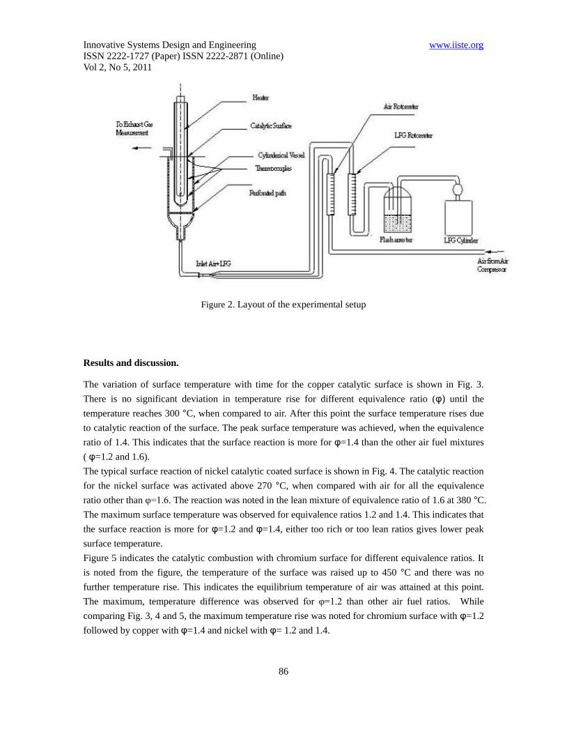
The experimental setup is fabricated using a simple vertically mounted furnace, which consists of a
170 mm long section, 90 mm inner diameter and 100 outer diameters. At the bottom of the vessel,
perforated section is provided for uniform flow of air fuel mixture. Inner side of this vessel one
cylindrical tube coated with the required material is placed, whose inner diameter is 44 mm and outer
diameter is 50 mm and a height of 300 mm out of which 136 mm is placed inside the cylindrical
vessel. An electrical heater is placed inside the inner tube. The layout of the experimental setup is
shown in fig.2. The heater is placed inside the metal tube surface, which is again placed inside the
cylindrical vessel. The heater is switched on and the steady state temperature of 100 °C is maintained.
The air is flows from the compressor to the cylindrical tube through an air Rota meter and through
perforated holes. The temperatures at top, bottom, packed region, inlet and outlet locations were noted
at every 60 seconds intervals. The fuel flow from the LPG cylinder through the fuel Rota meter. The
air and fuel are mixed in the mixing chamber; this mixture is passed over the heated surface. The
temperature versus time was noted for the same locations. The procedure is repeated by changing the
different coated surfaces.
Page 5
Innovative Systems Design and Engineering www.iiste.org
ISSN 2222-1727 (Paper) ISSN 2222-2871 (Online)
Vol 2, No 5, 2011
86
Figure 2. Layout of the experimental setup
Results and discussion.
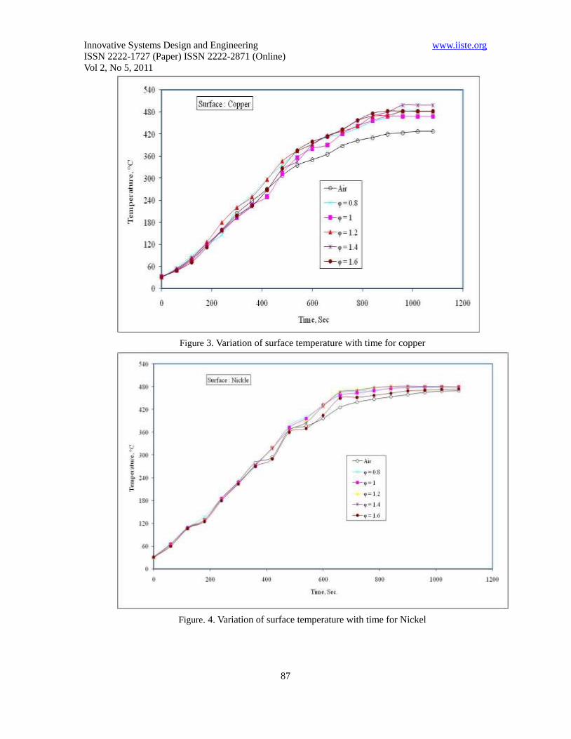
The variation of surface temperature with time for the copper catalytic surface is shown in Fig. 3.
There is no significant deviation in temperature rise for different equivalence ratio (φ) until the
temperature reaches 300 °C, when compared to air. After this point the surface temperature rises due
to catalytic reaction of the surface. The peak surface temperature was achieved, when the equivalence
ratio of 1.4. This indicates that the surface reaction is more for φ=1.4 than the other air fuel mixtures
( φ=1.2 and 1.6).
The typical surface reaction of nickel catalytic coated surface is shown in Fig. 4. The catalytic reaction
for the nickel surface was activated above 270 °C, when compared with air for all the equivalence
ratio other than φ=1.6. The reaction was noted in the lean mixture of equivalence ratio of 1.6 at 380 °C.
The maximum surface temperature was observed for equivalence ratios 1.2 and 1.4. This indicates that
the surface reaction is more for φ=1.2 and φ=1.4, either too rich or too lean ratios gives lower peak
surface temperature.
Figure 5 indicates the catalytic combustion with chromium surface for different equivalence ratios. It
is noted from the figure, the temperature of the surface was raised up to 450 °C and there was no
further temperature rise. This indicates the equilibrium temperature of air was attained at this point.
The maximum, temperature difference was observed for φ=1.2 than other air fuel ratios. While
comparing Fig. 3, 4 and 5, the maximum temperature rise was noted for chromium surface with φ=1.2
followed by copper with φ=1.4 and nickel with φ= 1.2 and 1.4.
Page 6
Innovative Systems Design and Engineering www.iiste.org
ISSN 2222-1727 (Paper) ISSN 2222-2871 (Online)
Vol 2, No 5, 2011
87
Figure 3. Variation of surface temperature with time for copper
Figure. 4. Variation of surface temperature with time for Nickel
Page 7
Innovative Systems Design and Engineering www.iiste.org
ISSN 2222-1727 (Paper) ISSN 2222-2871 (Online)
Vol 2, No 5, 2011
88
The inlet temperature was measured before the gas mixture enters to the chamber and exhaust
temperature was measured at the outlet of the test chamber. The differences in temperature for
different equivalence ratios with copper, nickel and chromium are given in Fig. 6, 7 and 8 respectively.
Form the Fig. 6, the maximum temperature difference was observed in rich mixture φ=0.8. However
for too lean mixture φ=1.6 there was no much variation in temperatures. It was observed maximum
temperature difference at φ=0.8 and φ=1,for lean mixture the temperature difference is very small it
shows in Fig.7 . From the Fig. 8 the maximum temperature was observed in the φ=1.2, and for
φ=0.8 and φ=1 maximum temperature obtained compare to φ=1.2 , the temperature difference is very
small.
Figure 5. Variation of surface temperature with time for chromium
It was observed from the Fig. 9 for copper material at rich mixture φ=0.8 φ=1 and φ=1.2 shows the
maximum temperature difference inlet and outlet But in lean mixture φ=1.4 and φ 1.6 maximum
temperature was observed in nickel material
Page 8
Innovative Systems Design and Engineering www.iiste.org
ISSN 2222-1727 (Paper) ISSN 2222-2871 (Online)
Vol 2, No 5, 2011
89
Figure. 6. Variation of inlet and outlet temperature difference with time for copper
Figure 7. Variation of inlet and outlet temperature difference with time for Nickel
Page 9
Innovative Systems Design and Engineering www.iiste.org
ISSN 2222-1727 (Paper) ISSN 2222-2871 (Online)
Vol 2, No 5, 2011
90
Figure 8. Variation of inlet and outlet temperature difference with time for Chromium
Figure 9. Comparison of maximum temperature difference with different catalytic surfaces
and equivalence ratios.
Page 10
Innovative Systems Design and Engineering www.iiste.org
ISSN 2222-1727 (Paper) ISSN 2222-2871 (Online)
Vol 2, No 5, 2011
91
5. Conclusion
From the above discussions the following conclusions are arrived.
For copper material at equivalence ratio(φ) of 1.4 at the point 300oC surface temperature rises
due to catalytic reaction of the surface the peak surface temperature obtained.
The catalytic reaction for the nickel surface shows activation above 270 °C,
when compared with air for all the equivalence ration other than φ=1.6. The reaction was
noted in the lean mixture of equivalence ratio of 1.6 at 380°C. The maximum surface
temperature was observed for equivalence ratios 1.2 and 1.
For chromium the maximum, temperature difference was observed for φ=1.2 than other air
fuel ratios. While comparing all the catalytic material, the maximum temperature rise was
noted for chromium surface with φ=1.2 followed by copper with φ=1.4 and nickel with φ=
1.2 and 1.4.
For copper material at rich mixture φ=0.8 φ=1 and φ=1.2 shows the maximum temperature
difference inlet and outlet But in lean mixture φ=1.4 and φ 1.6 maximum temperature was
observed in nickel material.
References
Ezekoye O, Greif, R., & Sawyer, R.F, Increased Surface Temperature Effects on Wall Heat
Transfer During Unsteady Flame Quenching, 24th Int. Symp. on Combustion, The
Combustion Institute, 1999,pp. 1465-1472.
Hautman D.J, Dryer F L, Schug K P & Glassman I, Combustion Science and Technology, Vol.
25, pp. 219, 1981
Jones, R.L , Catalytic Combustion in Internal Combustion Engines: A Possible Effect in
Thermally-Insulated Diesel Engines, Naval Research Laboratory Report,
No:NRL/MR/6170-96-7897, Washington, DC, Nov. 15, 1996
Karim G A, & Kibrya M G, Variations of the Lean Blowout Limit of a Homogeneous
Methane-Air Stream in the presence of a Metallic Wire Mesh, ASME Transactions, Vol. 108,
July 1986
Nedunchezhian N & Dhandapani S, Heat Release Analysis of Lean Burn Catalytic
Combustion in a Two-Stroke Spark ignition Engine, Combustion Science and Technology,
Vol. 155, pp. 181-201. 2000
Ramesh Babu, P, Nagalingam N, & Gopalakrishnen, K V, Effect of Certain Catalysts in the
Combustion Chamber of a Two-Stroke Engine on Exhaust Emissions, IMechE paper
C448/067, pp 241-246. 1992,
Robert L Jones ,catalytic combustion effects of m-zrO2 doped with various metal nitrates,
Surface and Coating Technology 86-87(1996) 127-134
Nomenclature
Eact – Activation energy
CO- carbon monoxide
Tcat – Catalytic surface temperature
Cr – Chromiun
Page 11
Innovative Systems Design and Engineering www.iiste.org
ISSN 2222-1727 (Paper) ISSN 2222-2871 (Online)
Vol 2, No 5, 2011
92
Cu – Copper
φ- Equivalence ratio
Ni – Nickel
NOx- Nitrogen oxides
PM - particulate matter
Ag – Silver
Page 12
This academic article was published by The International Institute for Science,
Technology and Education (IISTE). The IISTE is a pioneer in the Open Access
Publishing service based in the U.S. and Europe. The aim of the institute is
Accelerating Global Knowledge Sharing.
More information about the publisher can be found in the IISTE’s homepage:
http://www.iiste.org
The IISTE is currently hosting more than 30 peer-reviewed academic journals and
collaborating with academic institutions around the world. Prospective authors of
IISTE journals can find the submission instruction on the following page:
http://www.iiste.org/Journals/
The IISTE editorial team promises to the review and publish all the qualified
submissions in a fast manner. All the journals articles are available online to the
readers all over the world without financial, legal, or technical barriers other than
those inseparable from gaining access to the internet itself. Printed version of the
journals is also available upon request of readers and authors.
IISTE Knowledge Sharing Partners
EBSCO, Index Copernicus, Ulrich's Periodicals Directory, JournalTOCS, PKP Open
Archives Harvester, Bielefeld Academic Search Engine, Elektronische
Zeitschriftenbibliothek EZB, Open J-Gate, OCLC WorldCat, Universe Digtial
Library , NewJour, Google Scholar