Experimental investigation of fluid flow and heat transfer in a single-phase liquid flow micro-heat exchanger N. García-Hernando a, * , A. Acosta-Iborra a , U. Ruiz-Rivas a , M. Izquierdo b a Energy Systems Engineering Research Group, Departamento de Ingeniería Térmica y de Fluidos, Universidad Carlos III de Madrid, Avda. de la Universidad 30, Leganés, 28911 Madrid, Spain b Instituto de Ciencias de la Construcción Eduardo Torroja (CSIC), C/Serrano Galvache 4, 28033 Madrid, Spain abstract This work presents an experimental analysis of the hydrodynamic and thermal performance of micro heat exchangers. Two micro heat exchangers, characterized by microchannels of 100 100 and 200 200 lm square cross sections, were designed for that purpose. The fluid used was deionized water and there was no phase change along the fluid circuit. The fluid pressure drop along the heat exchanger and the heat transfer were measured and corrections were made to isolate the contribution of the micro channels. The results were compared with the predictions of the classical viscous flow and heat transfer theory. The main conclusions show that the experimental results fit well with these theories. No effects of heat transfer enhancement or pressure drop increase were observed as a consequence of the small scale of the microchannels. 1. Introduction The heat transfer processes between two fluids are common in many engineering systems, such as power plants, chemical reac tors or other power devices. But, while the equipment volume and weight must be constraint, the complexity of such systems is continuously increasing. This is the case, for example, of electronic devices, which should release heat with an increasing capacity per unit area. The direct consequence of these needs is an increasing interest in the miniaturization of heat transfer equipment to obtain micro heat exchangers, where two fluids circulating through chan nels of small cross section (microchannels) interchange heat. Several investigators have proposed relevant classifications of channels according to their dimension. Tables 1 and 2 show the classifications proposed by Mehendale et al. [1] and Kandlikar and Grande [2]. Both classifications are defined over the value of the smaller dimension of the channels. The most important parameters of a micro heat exchanger without phase change in practical applications are the frictional losses and the overall heat transfer coefficient. Most of the works published in the literature study and analyze such parameters, the deviations observed from the predictions of classical theory and, when they appear, the mechanisms involved in such deviations. Already in 1981, Tuckerman and Pease [3] designed and charac terized a micro heat exchanger for the refrigeration of electronic devices. The channels were 50 lm wide and 300 lm deep. They used deionized water and the results obtained showed good agree ment with the classical theory of laminar flow. The thermal resis tance was independent of the mass flow rate when the conditions of fully developed laminar flow were maintained. Later, Wu and Little [4] focused their efforts on the analysis of pressure drop for channels with equivalent diameters ranging from 50 to 80 lm. Their results showed that the friction factors obtained were much higher than those predicted by the theory. Since this work, a vast amount of experimental studies have been published with very dif ferent results. In their revisions of previous work, Morini [5] and Steinke and Kandlikar [6] showed that, while some researchers ob serve a general agreement with the classical theory in both heat transfer and pressure drop, others show a small increase of both magnitudes. The general discrepancies of such results have to be analyzed. To some extent, they can be a consequence of the uncertainties on the measurement process. In this sense, the proper determina tion of the microchannel characteristic diameter is of major impor tance to obtain an accurate friction factor. Also, temperature measurements, with the necessary precision, are difficult to obtain. Another possible explanation is the influence of the entrance re gion, because most of the works consider the flow to be fully devel oped. Moreover, as Steinke and Kandlikar [6] and Kohl et al. [7] show, the inlet and outlet effects should be carefully considered for a proper statement of the pressure drop along the channels. In recent investigations, Chakraborty and co workers [8 10], focus on the surface characteristics of microchannels and model the complex mechanisms by which roughness and hydrophobic effects * Corresponding author. Tel.: +34 916 248 885; fax: +34 916 249 430. E-mail address: [email protected](N. García-Hernando). 1
Transcript
Experimental investigation of fluid flow and heat transfer in a single-phaseliquid flow micro-heat exchanger
N. García-Hernando a,*, A. Acosta-Iborra a, U. Ruiz-Rivas a, M. Izquierdo b
a Energy Systems Engineering Research Group, Departamento de Ingeniería Térmica y de Fluidos, Universidad Carlos III de Madrid, Avda. de la Universidad 30,Leganés, 28911 Madrid, Spainb Instituto de Ciencias de la Construcción Eduardo Torroja (CSIC), C/Serrano Galvache 4, 28033 Madrid, Spain
This work presents an experimental analysis of the hydrodynamic and thermal performance of microheat exchangers. Two micro heat exchangers, characterized by microchannels of 100 � 100 and200 � 200 lm square cross sections, were designed for that purpose. The fluid used was deionized waterand there was no phase change along the fluid circuit. The fluid pressure drop along the heat exchangerand the heat transfer were measured and corrections were made to isolate the contribution of the microchannels. The results were compared with the predictions of the classical viscous flow and heat transfertheory. The main conclusions show that the experimental results fit well with these theories. No effects ofheat transfer enhancement or pressure drop increase were observed as a consequence of the small scaleof the microchannels.
1. Introduction devices. The channels were 50 lm wide and 300 lm deep. They
The heat transfer processes between two fluids are common inmany engineering systems, such as power plants, chemical reactors or other power devices. But, while the equipment volumeand weight must be constraint, the complexity of such systems iscontinuously increasing. This is the case, for example, of electronicdevices, which should release heat with an increasing capacity perunit area. The direct consequence of these needs is an increasinginterest in the miniaturization of heat transfer equipment to obtainmicro heat exchangers, where two fluids circulating through channels of small cross section (microchannels) interchange heat.
Several investigators have proposed relevant classifications ofchannels according to their dimension. Tables 1 and 2 show theclassifications proposed by Mehendale et al. [1] and Kandlikarand Grande [2]. Both classifications are defined over the value ofthe smaller dimension of the channels.
The most important parameters of a micro heat exchangerwithout phase change in practical applications are the frictionallosses and the overall heat transfer coefficient. Most of the workspublished in the literature study and analyze such parameters,the deviations observed from the predictions of classical theoryand, when they appear, the mechanisms involved in suchdeviations.
Already in 1981, Tuckerman and Pease [3] designed and characterized a micro heat exchanger for the refrigeration of electronic
: +34 916 249 430.ernando).
used deionized water and the results obtained showed good agreement with the classical theory of laminar flow. The thermal resistance was independent of the mass flow rate when the conditionsof fully developed laminar flow were maintained. Later, Wu andLittle [4] focused their efforts on the analysis of pressure drop forchannels with equivalent diameters ranging from 50 to 80 lm.Their results showed that the friction factors obtained were muchhigher than those predicted by the theory. Since this work, a vastamount of experimental studies have been published with very different results. In their revisions of previous work, Morini [5] andSteinke and Kandlikar [6] showed that, while some researchers observe a general agreement with the classical theory in both heattransfer and pressure drop, others show a small increase of bothmagnitudes.
The general discrepancies of such results have to be analyzed.To some extent, they can be a consequence of the uncertaintieson the measurement process. In this sense, the proper determination of the microchannel characteristic diameter is of major importance to obtain an accurate friction factor. Also, temperaturemeasurements, with the necessary precision, are difficult to obtain.Another possible explanation is the influence of the entrance region, because most of the works consider the flow to be fully developed. Moreover, as Steinke and Kandlikar [6] and Kohl et al. [7]show, the inlet and outlet effects should be carefully consideredfor a proper statement of the pressure drop along the channels.In recent investigations, Chakraborty and co workers [8 10], focuson the surface characteristics of microchannels and model thecomplex mechanisms by which roughness and hydrophobic effects
Published in: International Journal of Heat and Mass Transfer, 2009, vol. 52, nº 23-24, p. 5433-5446
Nomenclature
A elementary conduction areaAb microchannel bottom areaAc fin cross sectional areaAg plate projected areaD smaller dimension of the channelDh hydraulic diameterc specific heatC heat capacityCr heat capacity ratiof friction factorH microchannel depthh convective heat transfer coefficientks steel thermal conductivityLm microchannel length_m mass flow rate
N number of microchannelsNu Nusselt numberNux,3 local three sided microchannel Nusselt NumberNux,4 local four sided microchannel Nusselt NumberP fin perimeterPin inlet pressurePout outlet pressurePr Prandtl numberQ heat rateRe Reynolds numberRfin fin thermal resistanceRh convection thermal resistanceRT elementary thermal resistance between flowst thicknessT temperatureU overall heat transfer coefficientV velocity
W microchannel widthx x coordinatex* non dimensional microchannel length
Subscriptsapp apparentc cold flowci cold flow inletco cold flow outletexp experimentalfd fully developed flowh hot flowhi hot flow inletho hot flow outleti plate side (hot or cold flow)in inletip inlet plenumit inlet tubem microchannelmax maximummin minimumop outlet plenumot outlet tubeout outletp plenumt tube
might alter the fluid flow parameters as compared to classicaltheory.
Finally, other effects have also been stated in the literature, suchas the presence of incondensables (Ghiaasiaan and Laker [11]), themicropolar theory (Papautsky et al. [12]), the viscous dissipation(Tso and Mahulikar [13 15]) and the electrical double layer, EDL(Mala et al. [16], Yang and Li [17,18] and Li [19]). Nevertheless,and as Steinke and Kandlikar [6] stated, all these last factors canbe neglected for microchannels with diameters larger than 10 lm.
This work presents an experimental analysis of the hydrodynamic and thermal performance of two micro heat exchangers,
Table 1Mehendale et al. [1] classification scheme.
Conventional passages D > 6 mmCompact passages 1 mm < D < 6 mmMeso-channels 100 lm < D < 1 mmMicrochannels 1 lm < D < 100 lm
Table 2Kandlikar and Grande [2] classification scheme.
Conventional channels D > 3 mmMinichannels 200 lm < D < 3 mmMicrochannels 10 lm < D < 200 lmTransitional microchannels 1 lm < D < 10 lmTransitional nanochannels 0.1 lm < D < 1 lmNanochannels D < 0.1 lm
characterized by microchannels of 100 � 100 and 200 � 200 lmsquare cross sections. The object is to check if the hydrodynamicand thermal behavior agrees with the classical theory in both heattransfer and pressure drop.
2. Micro-heat exchanger prototypes and experimental facility
We will focus our characterization in global values for the heatexchanger, measuring the thermal and hydrodynamic characteristics between the inlet and the outlet, rather than analyzing theindividual behavior of the flow in each microchannel.
The design of the experimental facility and its components depends on the micro heat exchanger dimensions. The microchannelhydraulic diameter and the cross area shape are restricted by theavailable fabrication technique. Micro mechanization is the technique employed, which gives a reasonable mechanization qualityfor square cross sectional area for channels of at least 100 lm inheight. It is important to remark the influence that the microfabrication method and its mechanical characteristics have in the frictional behavior of liquid microflows. In this sense, Chakrabortyet al. [20] have presented a method for evaluating the microchannel characteristics as a function of the microfabrication processparameters.
Then, the structure and flow configuration of the micro heatexchanger has to be considered. We work with a liquid liquidexchanger without phase change in counter current disposition.A layout of channels at both sides of a plate has been used forefficiency and simplicity purposes. The plate should be thin (as
2
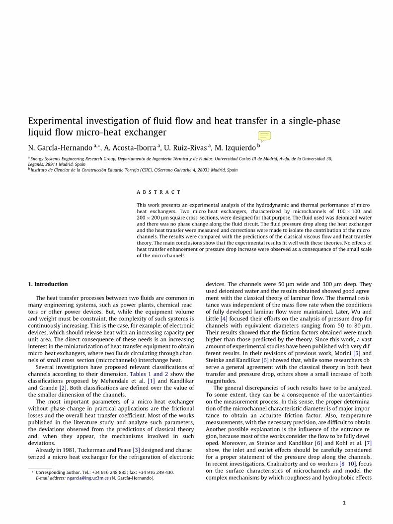
Fig. 2. Layout of the transparent medium.
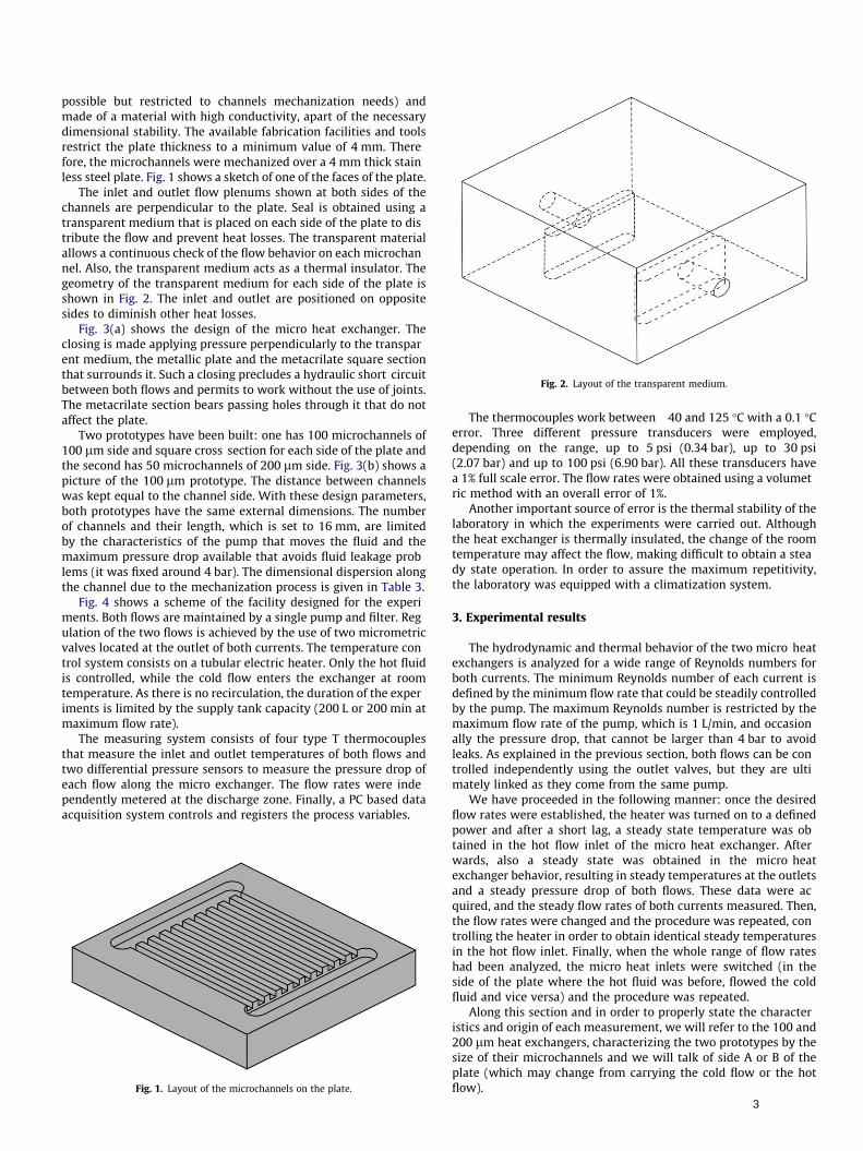
possible but restricted to channels mechanization needs) andmade of a material with high conductivity, apart of the necessarydimensional stability. The available fabrication facilities and toolsrestrict the plate thickness to a minimum value of 4 mm. Therefore, the microchannels were mechanized over a 4 mm thick stainless steel plate. Fig. 1 shows a sketch of one of the faces of the plate.
The inlet and outlet flow plenums shown at both sides of thechannels are perpendicular to the plate. Seal is obtained using atransparent medium that is placed on each side of the plate to distribute the flow and prevent heat losses. The transparent materialallows a continuous check of the flow behavior on each microchannel. Also, the transparent medium acts as a thermal insulator. Thegeometry of the transparent medium for each side of the plate isshown in Fig. 2. The inlet and outlet are positioned on oppositesides to diminish other heat losses.
Fig. 3(a) shows the design of the micro heat exchanger. Theclosing is made applying pressure perpendicularly to the transparent medium, the metallic plate and the metacrilate square sectionthat surrounds it. Such a closing precludes a hydraulic short circuitbetween both flows and permits to work without the use of joints.The metacrilate section bears passing holes through it that do notaffect the plate.
Two prototypes have been built: one has 100 microchannels of100 lm side and square cross section for each side of the plate andthe second has 50 microchannels of 200 lm side. Fig. 3(b) shows apicture of the 100 lm prototype. The distance between channelswas kept equal to the channel side. With these design parameters,both prototypes have the same external dimensions. The numberof channels and their length, which is set to 16 mm, are limitedby the characteristics of the pump that moves the fluid and themaximum pressure drop available that avoids fluid leakage problems (it was fixed around 4 bar). The dimensional dispersion alongthe channel due to the mechanization process is given in Table 3.
Fig. 4 shows a scheme of the facility designed for the experiments. Both flows are maintained by a single pump and filter. Regulation of the two flows is achieved by the use of two micrometricvalves located at the outlet of both currents. The temperature control system consists on a tubular electric heater. Only the hot fluidis controlled, while the cold flow enters the exchanger at roomtemperature. As there is no recirculation, the duration of the experiments is limited by the supply tank capacity (200 L or 200 min atmaximum flow rate).
The measuring system consists of four type T thermocouplesthat measure the inlet and outlet temperatures of both flows andtwo differential pressure sensors to measure the pressure drop ofeach flow along the micro exchanger. The flow rates were independently metered at the discharge zone. Finally, a PC based dataacquisition system controls and registers the process variables.
Fig. 1. Layout of the microchannels on the plate.
The thermocouples work between 40 and 125 �C with a 0.1 �Cerror. Three different pressure transducers were employed,depending on the range, up to 5 psi (0.34 bar), up to 30 psi(2.07 bar) and up to 100 psi (6.90 bar). All these transducers havea 1% full scale error. The flow rates were obtained using a volumetric method with an overall error of 1%.
Another important source of error is the thermal stability of thelaboratory in which the experiments were carried out. Althoughthe heat exchanger is thermally insulated, the change of the roomtemperature may affect the flow, making difficult to obtain a steady state operation. In order to assure the maximum repetitivity,the laboratory was equipped with a climatization system.
3. Experimental results
The hydrodynamic and thermal behavior of the two micro heatexchangers is analyzed for a wide range of Reynolds numbers forboth currents. The minimum Reynolds number of each current isdefined by the minimum flow rate that could be steadily controlledby the pump. The maximum Reynolds number is restricted by themaximum flow rate of the pump, which is 1 L/min, and occasionally the pressure drop, that cannot be larger than 4 bar to avoidleaks. As explained in the previous section, both flows can be controlled independently using the outlet valves, but they are ultimately linked as they come from the same pump.
We have proceeded in the following manner: once the desiredflow rates were established, the heater was turned on to a definedpower and after a short lag, a steady state temperature was obtained in the hot flow inlet of the micro heat exchanger. Afterwards, also a steady state was obtained in the micro heatexchanger behavior, resulting in steady temperatures at the outletsand a steady pressure drop of both flows. These data were acquired, and the steady flow rates of both currents measured. Then,the flow rates were changed and the procedure was repeated, controlling the heater in order to obtain identical steady temperaturesin the hot flow inlet. Finally, when the whole range of flow rateshad been analyzed, the micro heat inlets were switched (in theside of the plate where the hot fluid was before, flowed the coldfluid and vice versa) and the procedure was repeated.
Along this section and in order to properly state the characteristics and origin of each measurement, we will refer to the 100 and200 lm heat exchangers, characterizing the two prototypes by thesize of their microchannels and we will talk of side A or B of theplate (which may change from carrying the cold flow or the hotflow).
3
Fig. 3. Design of the micro-heat exchanger, showing the principal parts and a picture of the 100 lm prototype.
Fig. 5. Longitudinal cut of the heat exchanger, showing the fluid circulation.
Table 3Dimensional dispersion of the microchannels (Leitz coordinate measuring machine).
100 lm microchannel 200 lm microchannel
Height dispersion along the channelMaximum ±18% ±8%St. deviation ±6% ±5%
Width dispersion along the channelMaximum ±22% ±8%St. deviation ±12% ±4%
Surface roughnessMaximum 0.033 lm 0.028 lm
3.1. Microchannels pressure drop
The pressure difference measurements made in the facility donot consist only on the pressure drop along the microchannels,but represent a global pressure drop along the heat exchanger,including the pressure drop also in the two distributors and inthe connecting ducts. Therefore, the different sources of pressuredrop have to be analyzed separately.
Filter
Supply Tank
Pump
Heater
Hot f
Cold fl
Tco
Thin
Fig. 4. Scheme of the ex
Fig. 5 shows a scheme of the fluid circulation inside the heat exchanger. The fluid enters the heat exchanger in Section 1, but theinlet pressure is measured 5 cm upflow. In Section 1 the flow enters a plenum chamber and the fluid suffers a sudden expansion,from the 4 mm duct to the chamber (20 mm wide) and, therefore,the pressure drops. Then, the fluid flows along the chamber and, inSection 2, it enters the microchannels with a sudden contractionfrom the chamber to a total cross section of the array of
lux diff. pressure sensor
Cold flux valve
ux diff. pressure sensor
Discharge Tank
Hot flux valve
Micro HeatExchanger
utTc
in
Thout
perimental facility.
4
microchannels of 1 or 2 mm2 (depending on the prototype, 100microchannels of 100 lm side or 50 microchannels of 200 lmside). The result is another local pressure drop. Finally, the fluidflows through the microchannels and it suffers a sudden expansionat Section 3 and a sudden contraction at Section 4. The changes offlow direction entering and exiting the plenums will also producepressure drops.
Of all these pressure drops, only the ones produced by the sudden contraction and the sudden expansion at the entrance and theexit of the microchannel, and the pressure drop in the microchannel are of importance. The fluid velocity is low at the inlet and outlet and in the plenums, and the changes of flow direction will causenegligible pressure drops, as the plenum dimension is far largerthan the tube or microchannel diameter.
Therefore, the global pressure drop that is measured betweeninlet and outlet comes from several sources: two expansions (Sections 1 and 3), two contractions (Sections 2 and 4), the viscous flowin the inlet and outlet tubes (subscripts it and ot), the viscous flowin the inlet and outlet plenums (subscripts ip and op) and, finally,the viscous flow along the microchannels. This is stated in the following equation:
Eq. (1) can be expanded, using loss coefficients, K (obtainedfrom Kandlikar et al. [21] and supported by recent data obtainedby Abdelall et al. [22]), friction factors, f (obtained of well established data and correlations), and the apparent friction factor alongthe microchannels, fapp, giving Eq. (2):
Dptotal12
fappLm
Dhqm V2
m þ12
K1q1 V21 þ
12
K2q2 V22 þ
12
K3q3 V23
þ 12
K4q4 V24 þþ
12
fitLit
Dtqi V2
it þ12
fipLp
Dpqi V2
ip
þ 12
fopLp
Dpqo V2
op þ12
fotLot
Dtqo V2
ot ð2Þ
Fig. 6. Pressure drop alon
where the density, q, is evaluated before Section 2 at the inlet temperature, after Section 3 at the outlet temperature and in the microchannels at the average temperature.
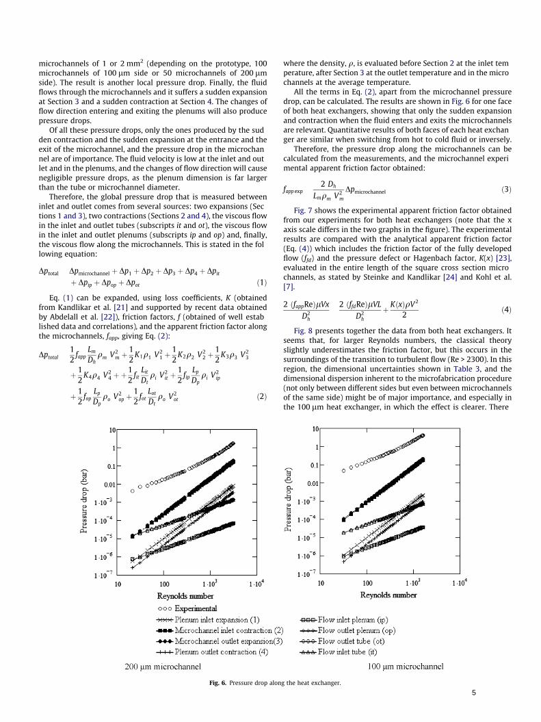
All the terms in Eq. (2), apart from the microchannel pressuredrop, can be calculated. The results are shown in Fig. 6 for one faceof both heat exchangers, showing that only the sudden expansionand contraction when the fluid enters and exits the microchannelsare relevant. Quantitative results of both faces of each heat exchanger are similar when switching from hot to cold fluid or inversely.
Therefore, the pressure drop along the microchannels can becalculated from the measurements, and the microchannel experimental apparent friction factor obtained:
fapp exp2 Dh
Lmqm V2m
Dpmicrochannel ð3Þ
Fig. 7 shows the experimental apparent friction factor obtainedfrom our experiments for both heat exchangers (note that the xaxis scale differs in the two graphs in the figure). The experimentalresults are compared with the analytical apparent friction factor(Eq. (4)) which includes the friction factor of the fully developedflow (ffd) and the pressure defect or Hagenbach factor, K(x) [23],evaluated in the entire length of the square cross section microchannels, as stated by Steinke and Kandlikar [24] and Kohl et al.[7].
2 ðfappReÞlVx
D2h
2 ðffdReÞlVL
D2h
þ KðxÞqV2
2ð4Þ
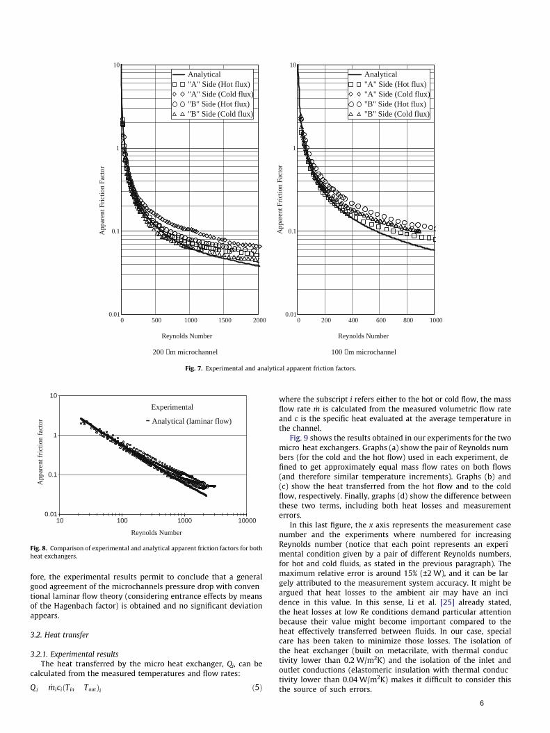
Fig. 8 presents together the data from both heat exchangers. Itseems that, for larger Reynolds numbers, the classical theoryslightly underestimates the friction factor, but this occurs in thesurroundings of the transition to turbulent flow (Re > 2300). In thisregion, the dimensional uncertainties shown in Table 3, and thedimensional dispersion inherent to the microfabrication procedure(not only between different sides but even between microchannelsof the same side) might be of major importance, and especially inthe 100 lm heat exchanger, in which the effect is clearer. There
g the heat exchanger.
5
0 500 1000 1500 20000.01
0.1
1
10
Analytical"A" Side (Hot flux) "A" Side (Cold flux)"B" Side (Hot flux)"B" Side (Cold flux)
Analytical"A" Side (Hot flux) "A" Side (Cold flux)"B" Side (Hot flux)"B" Side (Cold flux)
Reynolds Number
App
aren
t Fri
ctio
n Fa
ctor
0 200 400 600 800 10000.01
0.1
1
10
Analytical"A" Side (Hot flux) "A" Side (Cold flux)"B" Side (Hot flux)"B" Side (Cold flux)
Analytical"A" Side (Hot flux) "A" Side (Cold flux)"B" Side (Hot flux)"B" Side (Cold flux)
Reynolds Number
App
aren
t Fri
ctio
n Fa
ctor
200 µm microchannel 100 µm microchannel
Fig. 7. Experimental and analytical apparent friction factors.
0.01
0.1
1
10
10 100 1000 10000
Reynolds Number
App
aren
t fri
ctio
n fa
ctor
• Experimental
- Analytical (laminar flow)
Fig. 8. Comparison of experimental and analytical apparent friction factors for bothheat exchangers.
fore, the experimental results permit to conclude that a generalgood agreement of the microchannels pressure drop with conventional laminar flow theory (considering entrance effects by meansof the Hagenbach factor) is obtained and no significant deviationappears.
3.2. Heat transfer
3.2.1. Experimental resultsThe heat transferred by the micro heat exchanger, Qi, can be
calculated from the measured temperatures and flow rates:
Q i _miciðTin ToutÞi ð5Þ
where the subscript i refers either to the hot or cold flow, the massflow rate _m is calculated from the measured volumetric flow rateand c is the specific heat evaluated at the average temperature inthe channel.
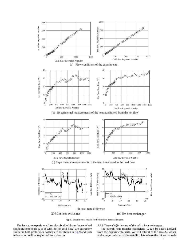
Fig. 9 shows the results obtained in our experiments for the twomicro heat exchangers. Graphs (a) show the pair of Reynolds numbers (for the cold and the hot flow) used in each experiment, defined to get approximately equal mass flow rates on both flows(and therefore similar temperature increments). Graphs (b) and(c) show the heat transferred from the hot flow and to the coldflow, respectively. Finally, graphs (d) show the difference betweenthese two terms, including both heat losses and measurementerrors.
In this last figure, the x axis represents the measurement casenumber and the experiments where numbered for increasingReynolds number (notice that each point represents an experimental condition given by a pair of different Reynolds numbers,for hot and cold fluids, as stated in the previous paragraph). Themaximum relative error is around 15% (±2 W), and it can be largely attributed to the measurement system accuracy. It might beargued that heat losses to the ambient air may have an incidence in this value. In this sense, Li et al. [25] already stated,the heat losses at low Re conditions demand particular attentionbecause their value might become important compared to theheat effectively transferred between fluids. In our case, specialcare has been taken to minimize those losses. The isolation ofthe heat exchanger (built on metacrilate, with thermal conductivity lower than 0.2 W/m2K) and the isolation of the inlet andoutlet conductions (elastomeric insulation with thermal conductivity lower than 0.04 W/m2K) makes it difficult to consider thisthe source of such errors.
6
0 500 1000 15000
500
1000
1500
2000
Cold flow Reynolds Number
Hot
flo
w R
eyno
lds
Num
ber
0 250 500 750 10000
500
1000
1500
2000
Cold flow Reynolds Number
Hot
flo
w R
eyno
lds
Num
ber
(a) Flow conditions of the experiments
0 200 400 600 800 1000 1200 1400 16000
10
20
30
40
Hot flow Reynolds Number
Hot
flo
w H
eat R
ate
(W)
0 200 400 600 800 1000 1200 1400 16000
10
20
30
40
Hot flow Reynolds Number
Hot
flo
w H
eat R
ate
(W)
(b) Experimental measurements of the heat transferred from the hot flow
0 200 400 600 800 1000 12000
10
20
30
40
Cold flow Reynolds Number
Col
d fl
ow H
eat R
ate
(W)
0 200 400 600 800 10000
10
20
30
40
Cold flow Reynolds Number
Col
d fl
ow H
eat R
ate
(W)
(c) Experimental measurements of the heat transferred to the cold flow
0 10 20 30 40 50 0 10 20 30 40 5020
10
0
10
20
4
2
0
2
4
%absolute (W)%absolute (W)
Measure Case
Hea
t Rat
e D
iffe
renc
e (%
)
Hea
t Rat
e D
iffe
renc
e (W
)
20
10
0
10
20
4
2
0
2
4
%absolute (W)%absolute (W)
Measure Case
Hea
t Rat
e D
iffe
renc
e (%
)
Hea
t Rat
e D
iffe
renc
e (W
)
(d) Heat Rate difference
200 µm heat exchanger 100 µm heat exchanger
Fig. 9. Experimental results for both micro-heat exchangers.
The heat rate experimental results obtained from the switchedconfigurations (side A or B with hot or cold flow) are extremelysimilar in both prototypes, so they are not shown in Fig. 9 and suchinformation will be neglected from now on.
3.2.2. Thermal effectiveness of the micro heat exchangersThe overall heat transfer coefficient, U, can be easily derived
from the experimental data. We will refer it to the area AG, whichis the projected area of the metallic plate where the microchannels
have been mechanized (20 mm width � 16 mm length for bothprototypes)
Q UAGDTLM ! UQ
AGDTLM
DTLMDT1 DT2
lnDT1DT2
DT1 Thi Tco
DT2 Tho Tci
8>><>>:
ð6Þ
where the subscript hi represents the hot flow inlet, ci the cold flowinlet, ho the hot flow outlet and co the cold flow outlet. Note thatthe temperature at the hot flow outlet can be lower than thatat the cold flow outlet, as we are using a counterflow heatexchanger.
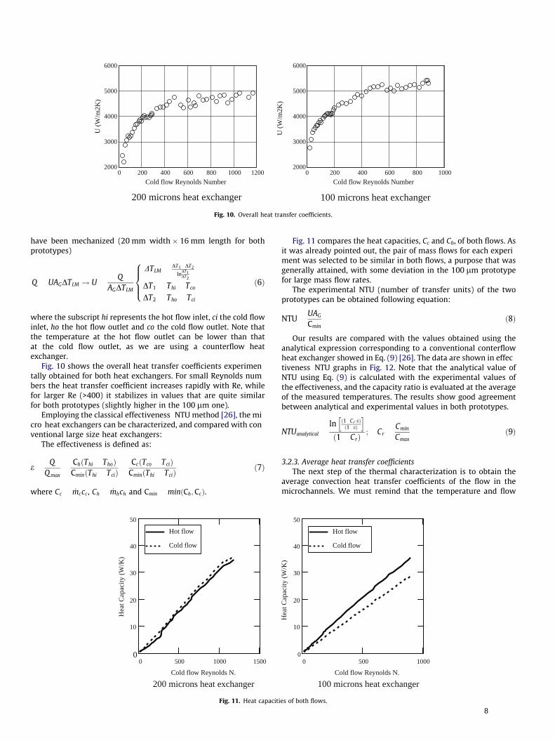
Fig. 10 shows the overall heat transfer coefficients experimentally obtained for both heat exchangers. For small Reynolds numbers the heat transfer coefficient increases rapidly with Re, whilefor larger Re (>400) it stabilizes in values that are quite similarfor both prototypes (slightly higher in the 100 lm one).
Employing the classical effectiveness NTU method [26], the micro heat exchangers can be characterized, and compared with conventional large size heat exchangers:
The effectiveness is defined as:
eQ
Q max
ChðThi ThoÞCminðThi TciÞ
CcðTco TciÞCminðThi TciÞ
ð7Þ
where Cc _mccc , Ch _mhch and Cmin minðCh;CcÞ.
0 500 1000 15000
10
20
30
40
50
Hot flow
Cold flow
Cold flow Reynolds N.
Hea
t Cap
acity
(W
/K)
200 microns heat exchanger
Fig. 11. Heat capaciti
Fig. 11 compares the heat capacities, Cc and Ch, of both flows. Asit was already pointed out, the pair of mass flows for each experiment was selected to be similar in both flows, a purpose that wasgenerally attained, with some deviation in the 100 lm prototypefor large mass flow rates.
The experimental NTU (number of transfer units) of the twoprototypes can be obtained following equation:
NTUUAG
Cminð8Þ
Our results are compared with the values obtained using theanalytical expression corresponding to a conventional conterflowheat exchanger showed in Eq. (9) [26]. The data are shown in effectiveness NTU graphs in Fig. 12. Note that the analytical value ofNTU using Eq. (9) is calculated with the experimental values ofthe effectiveness, and the capacity ratio is evaluated at the averageof the measured temperatures. The results show good agreementbetween analytical and experimental values in both prototypes.
NTUanalytical
ln ð1 Cr �eÞð1 eÞ
h ið1 CrÞ
; CrCmin
Cmaxð9Þ
3.2.3. Average heat transfer coefficientsThe next step of the thermal characterization is to obtain the
average convection heat transfer coefficients of the flow in themicrochannels. We must remind that the temperature and flow
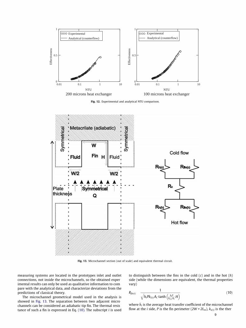
Fig. 12. Experimental and analytical NTU comparison.
Fig. 13. Microchannel section (out of scale) and equivalent thermal circuit.
measuring systems are located in the prototypes inlet and outletconnections, not inside the microchannels, so the obtained experimental results can only be used as qualitative information to compare with the analytical data, and characterize deviations from thepredictions of classical theory.
The microchannel geometrical model used in the analysis isshowed in Fig. 13. The separation between two adjacent microchannels can be considered an adiabatic tip fin. The thermal resistance of such a fin is expressed in Eq. (10). The subscript i is used
to distinguish between the fins in the cold (c) and in the hot (h)side (while the dimensions are equivalent, the thermal propertiesvary)
RfinðiÞ1
hiPkSðiÞAC
qtanh hiP
kSðiÞACH
� � ð10Þ
where �hi is the average heat transfer coefficient of the microchannelflow at the i side, P is the fin perimeter (2W + 2Lm), ks(i) is the ther
9
mal conductivity of the fin material (stainless steel), evaluated atthe average temperature of the corresponding plate side, Ac is thefin cross sectional area (WLm) and H is the fin length that in thiscase is the microchannel depth.
Parallel to the fin resistance, the convection thermal resistancecan be written as:
RhðiÞ1
hiAb
ð11Þ
where Ab is the microchannel bottom area (WLm).The conduction thermal resistance corresponding to the stain
less steel plate is given in Eq. (12). The thermal conductivity ð�ksÞis evaluated at the average temperature of the steel, which canbe obtained from the average temperatures of both fluids. A isthe conduction area (2WL) and t is the thickness (the plate thickness minus 2H).
Rct
ksAð12Þ
With Eqs. (10) (12), the total thermal resistance between bothflows for the plate element shown in Fig. 13 can be written as:
RT1
RfinðhÞþ 1
RhðhÞ
� � 1
þ Rc þ1
RfinðcÞþ 1
RhðcÞ
� � 1
ð13Þ
and the total thermal resistance between flows for the whole platewill be RT/N, being N the number of channels in each side of theplate (50 for the 200 lm exchanger and 100 for the 100 lm one).
Finally, the theoretical overall heat transfer coefficient, U, can beobtained as:
U1
AGRTð14Þ
The major parameters in this calculation are the average heattransfer coefficients in both sides of the plate. We have used thesame coefficient for Eqs. (10) and (11), but the temperature dependent variables have been calculated or evaluated separately for thehot and the cold flow sides.
The calculation of the average heat transfer coefficient of themicrochannel flow is obtained considering the effect of the entrance region and taking in mind that the microchannels havea square cross section where three sides are heated and theother one is adiabatic. Also, there is an important contractionat the inlet of the microchannels. As Rohsenow et al. [27] suggested and Lee et al. [28] verified, on such conditions the inletflow should be assumed as a fully developed flow in the hydrodynamic sense but thermally developing, and so it is assumed inthis work.
0 500 1000 15000
0.02
0.04
0.06
0.08
Hot flow entry lenghtCold flow entry lenghtMicrochannel lenght
Reynolds Number
Len
ght (
m)
200 microns heat exchanger
Fig. 14. Thermal en
The fully developed flow Nusselt number for three sided microchannels, Nufd,3, with an aspect ratio ðaC W=H 1Þ has a value of3.556 [21]. Then, the local Nusselt number in the thermal entranceregion can be obtained from Eq. (15) [21]
where x� x=DhRePr is the non dimensional microchannel length, the
subscript fd means fully developed flow, and the subscripts 3and 4 refer to the three sided and four sided microchannels,respectively. For four sided microchannels, the Nusselt numberfor fully developed flow is again obtained from Kandlikar et al.[21] (with a value of 3.599) and the local Nusselt number in theentrance region is calculated following Eq. (16) from Lee and Garimella [29]:
Nux;4ðx�;aCÞ1
C1ðx�ÞC2 þ C3
þ C4 1 � aC � 10 ð16Þ
where
C1 3:122� 10 3a3C þ 2:435� 10 2a2
C
þ 2:143� 10 1aC þ 7:325
C2 6:412� 10 1
C3 1:589� 10 4a2C 2:603� 10 3aC þ 2:444� 10 2
C4 7:148 1:328� 101=aC þ 1:515� 101=a2C 5:936=a3
C
This expression was obtained analyzing the microchannels heattransfer problem under the H1 thermal boundary condition (circumferentially constant temperature and axially constant heat fluxon the walls), which has been found as the best representingboundary condition of the four sided microchannels heat transfercase. Using the Phillips correction factor (Eq. (15)), it can be usedas well with three sided microchannels. Nevertheless, it shouldbe noted that this implies that the ratio of developing Nusseltnumbers for the three and four sided heating cases is identical tothat in fully developing flow [29].
The total length of the entrance region can be calculated fromLee and Garimella [29], where a non dimensional value of 0.062is considered for channels with an aspect ratio 1 ðaC 1Þ. Fig. 14shows the thermal entrance region lengths in our experimentalconditions (shown in Fig. 9(a)) as a function of the Reynolds number, and compared with the actual microchannel length (16 mm).
The results show that the entrance region is of paramountimportance in both prototypes. The microchannels are completelyunder entrance region flow conditions even for relatively low Reynolds numbers. The critical Reynolds numbers (where the entrancelength equals the actual length of the channel) are 486 and 760 for
0 500 1000 15000
0.01
0.02
0.03
0.04
Hot flow entry lenghtCold flow entry lenghtMicrochannel lenght
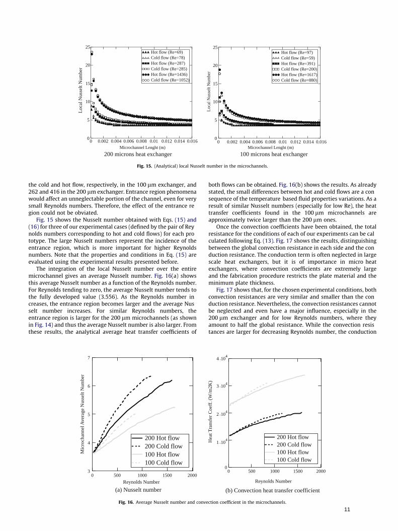
Fig. 15. (Analytical) local Nusselt number in the microchannels.
the cold and hot flow, respectively, in the 100 lm exchanger, and262 and 416 in the 200 lm exchanger. Entrance region phenomenawould affect an unneglectable portion of the channel, even for verysmall Reynolds numbers. Therefore, the effect of the entrance region could not be obviated.
Fig. 15 shows the Nusselt number obtained with Eqs. (15) and(16) for three of our experimental cases (defined by the pair of Reynolds numbers corresponding to hot and cold flows) for each prototype. The large Nusselt numbers represent the incidence of theentrance region, which is more important for higher Reynoldsnumbers. Note that the properties and conditions in Eq. (15) areevaluated using the experimental results presented before.
The integration of the local Nusselt number over the entiremicrochannel gives an average Nusselt number. Fig. 16(a) showsthis average Nusselt number as a function of the Reynolds number.For Reynolds tending to zero, the average Nusselt number tends tothe fully developed value (3.556). As the Reynolds number increases, the entrance region becomes larger and the average Nusselt number increases. For similar Reynolds numbers, theentrance region is larger for the 200 lm microchannels (as shownin Fig. 14) and thus the average Nusselt number is also larger. Fromthese results, the analytical average heat transfer coefficients of
0 500 1000 1500 20003
4
5
6
7
200 Hot flow 200 Cold flow100 Hot flow100 Cold flow
200 Hot flow 200 Cold flow100 Hot flow100 Cold flow
Reynolds Number
Mic
roch
anne
l Ave
rage
Nus
selt
Num
ber
(a) Nusselt number
Fig. 16. Average Nusselt number and conve
both flows can be obtained. Fig. 16(b) shows the results. As alreadystated, the small differences between hot and cold flows are a consequence of the temperature based fluid properties variations. As aresult of similar Nusselt numbers (especially for low Re), the heattransfer coefficients found in the 100 lm microchannels areapproximately twice larger than the 200 lm ones.
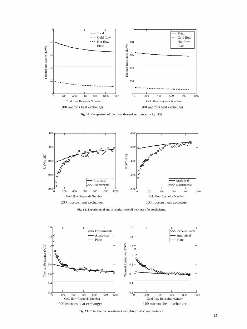
Once the convection coefficients have been obtained, the totalresistance for the conditions of each of our experiments can be calculated following Eq. (13). Fig. 17 shows the results, distinguishingbetween the global convection resistance in each side and the conduction resistance. The conduction term is often neglected in largescale heat exchangers, but it is of importance in micro heatexchangers, where convection coefficients are extremely largeand the fabrication procedure restricts the plate material and theminimum plate thickness.
Fig. 17 shows that, for the chosen experimental conditions, bothconvection resistances are very similar and smaller than the conduction resistance. Nevertheless, the convection resistances cannotbe neglected and even have a major influence, especially in the200 lm exchanger and for low Reynolds numbers, where theyamount to half the global resistance. While the convection resistances are larger for decreasing Reynolds number, the conduction
0 500 1000 1500 20000
1 .104
2 .104
3 .104
4 .104
200 Hot flow 200 Cold flow100 Hot flow100 Cold flow
200 Hot flow 200 Cold flow100 Hot flow100 Cold flow
Fig. 19. Total thermal resistances and plate conduction resistance.
12
resistance remains almost constant, as the mean temperature variations of the plate for the different experimental conditions aresmall and thus produce negligible heat conductivity variations.
Although this paper focuses on the convection effects, the conduction resistance has an obvious relevance. Therefore, the platethickness and plate material are critical design parameters. Fabrication processes for channel mechanization must allow smallerthicknesses (around 1 mm or less) or use materials with higherconductivity (around 100 W/mK or higher).
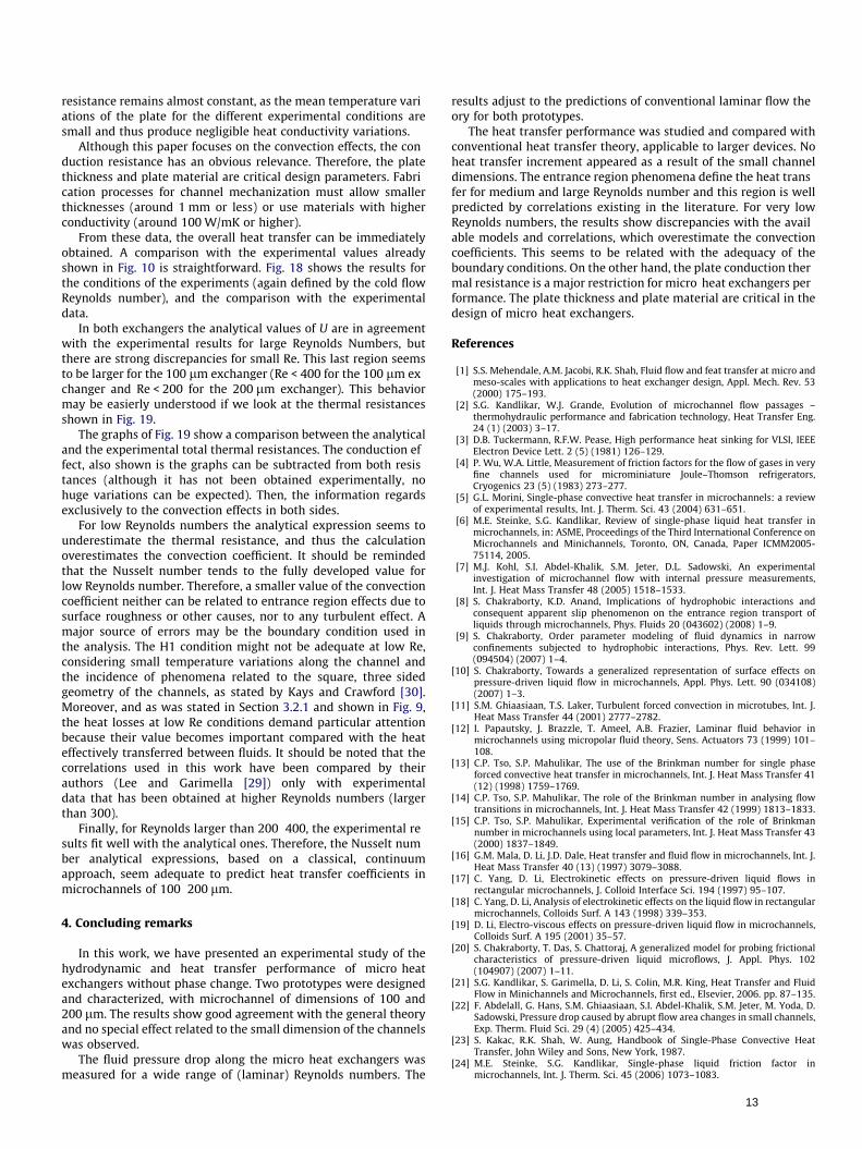
From these data, the overall heat transfer can be immediatelyobtained. A comparison with the experimental values alreadyshown in Fig. 10 is straightforward. Fig. 18 shows the results forthe conditions of the experiments (again defined by the cold flowReynolds number), and the comparison with the experimentaldata.
In both exchangers the analytical values of U are in agreementwith the experimental results for large Reynolds Numbers, butthere are strong discrepancies for small Re. This last region seemsto be larger for the 100 lm exchanger (Re < 400 for the 100 lm exchanger and Re < 200 for the 200 lm exchanger). This behaviormay be easierly understood if we look at the thermal resistancesshown in Fig. 19.
The graphs of Fig. 19 show a comparison between the analyticaland the experimental total thermal resistances. The conduction effect, also shown is the graphs can be subtracted from both resistances (although it has not been obtained experimentally, nohuge variations can be expected). Then, the information regardsexclusively to the convection effects in both sides.
For low Reynolds numbers the analytical expression seems tounderestimate the thermal resistance, and thus the calculationoverestimates the convection coefficient. It should be remindedthat the Nusselt number tends to the fully developed value forlow Reynolds number. Therefore, a smaller value of the convectioncoefficient neither can be related to entrance region effects due tosurface roughness or other causes, nor to any turbulent effect. Amajor source of errors may be the boundary condition used inthe analysis. The H1 condition might not be adequate at low Re,considering small temperature variations along the channel andthe incidence of phenomena related to the square, three sidedgeometry of the channels, as stated by Kays and Crawford [30].Moreover, and as was stated in Section 3.2.1 and shown in Fig. 9,the heat losses at low Re conditions demand particular attentionbecause their value becomes important compared with the heateffectively transferred between fluids. It should be noted that thecorrelations used in this work have been compared by theirauthors (Lee and Garimella [29]) only with experimentaldata that has been obtained at higher Reynolds numbers (largerthan 300).
Finally, for Reynolds larger than 200 400, the experimental results fit well with the analytical ones. Therefore, the Nusselt number analytical expressions, based on a classical, continuumapproach, seem adequate to predict heat transfer coefficients inmicrochannels of 100 200 lm.
4. Concluding remarks
In this work, we have presented an experimental study of thehydrodynamic and heat transfer performance of micro heatexchangers without phase change. Two prototypes were designedand characterized, with microchannel of dimensions of 100 and200 lm. The results show good agreement with the general theoryand no special effect related to the small dimension of the channelswas observed.
The fluid pressure drop along the micro heat exchangers wasmeasured for a wide range of (laminar) Reynolds numbers. The
results adjust to the predictions of conventional laminar flow theory for both prototypes.
The heat transfer performance was studied and compared withconventional heat transfer theory, applicable to larger devices. Noheat transfer increment appeared as a result of the small channeldimensions. The entrance region phenomena define the heat transfer for medium and large Reynolds number and this region is wellpredicted by correlations existing in the literature. For very lowReynolds numbers, the results show discrepancies with the available models and correlations, which overestimate the convectioncoefficients. This seems to be related with the adequacy of theboundary conditions. On the other hand, the plate conduction thermal resistance is a major restriction for micro heat exchangers performance. The plate thickness and plate material are critical in thedesign of micro heat exchangers.
References
[1] S.S. Mehendale, A.M. Jacobi, R.K. Shah, Fluid flow and feat transfer at micro andmeso-scales with applications to heat exchanger design, Appl. Mech. Rev. 53(2000) 175–193.
[2] S.G. Kandlikar, W.J. Grande, Evolution of microchannel flow passages –thermohydraulic performance and fabrication technology, Heat Transfer Eng.24 (1) (2003) 3–17.
[3] D.B. Tuckermann, R.F.W. Pease, High performance heat sinking for VLSI, IEEEElectron Device Lett. 2 (5) (1981) 126–129.
[4] P. Wu, W.A. Little, Measurement of friction factors for the flow of gases in veryfine channels used for microminiature Joule–Thomson refrigerators,Cryogenics 23 (5) (1983) 273–277.
[5] G.L. Morini, Single-phase convective heat transfer in microchannels: a reviewof experimental results, Int. J. Therm. Sci. 43 (2004) 631–651.
[6] M.E. Steinke, S.G. Kandlikar, Review of single-phase liquid heat transfer inmicrochannels, in: ASME, Proceedings of the Third International Conference onMicrochannels and Minichannels, Toronto, ON, Canada, Paper ICMM2005-75114, 2005.
[7] M.J. Kohl, S.I. Abdel-Khalik, S.M. Jeter, D.L. Sadowski, An experimentalinvestigation of microchannel flow with internal pressure measurements,Int. J. Heat Mass Transfer 48 (2005) 1518–1533.
[8] S. Chakraborty, K.D. Anand, Implications of hydrophobic interactions andconsequent apparent slip phenomenon on the entrance region transport ofliquids through microchannels, Phys. Fluids 20 (043602) (2008) 1–9.
[9] S. Chakraborty, Order parameter modeling of fluid dynamics in narrowconfinements subjected to hydrophobic interactions, Phys. Rev. Lett. 99(094504) (2007) 1–4.
[10] S. Chakraborty, Towards a generalized representation of surface effects onpressure-driven liquid flow in microchannels, Appl. Phys. Lett. 90 (034108)(2007) 1–3.
[11] S.M. Ghiaasiaan, T.S. Laker, Turbulent forced convection in microtubes, Int. J.Heat Mass Transfer 44 (2001) 2777–2782.
[12] I. Papautsky, J. Brazzle, T. Ameel, A.B. Frazier, Laminar fluid behavior inmicrochannels using micropolar fluid theory, Sens. Actuators 73 (1999) 101–108.
[13] C.P. Tso, S.P. Mahulikar, The use of the Brinkman number for single phaseforced convective heat transfer in microchannels, Int. J. Heat Mass Transfer 41(12) (1998) 1759–1769.
[14] C.P. Tso, S.P. Mahulikar, The role of the Brinkman number in analysing flowtransitions in microchannels, Int. J. Heat Mass Transfer 42 (1999) 1813–1833.
[15] C.P. Tso, S.P. Mahulikar, Experimental verification of the role of Brinkmannumber in microchannels using local parameters, Int. J. Heat Mass Transfer 43(2000) 1837–1849.
[16] G.M. Mala, D. Li, J.D. Dale, Heat transfer and fluid flow in microchannels, Int. J.Heat Mass Transfer 40 (13) (1997) 3079–3088.
[17] C. Yang, D. Li, Electrokinetic effects on pressure-driven liquid flows inrectangular microchannels, J. Colloid Interface Sci. 194 (1997) 95–107.
[18] C. Yang, D. Li, Analysis of electrokinetic effects on the liquid flow in rectangularmicrochannels, Colloids Surf. A 143 (1998) 339–353.
[19] D. Li, Electro-viscous effects on pressure-driven liquid flow in microchannels,Colloids Surf. A 195 (2001) 35–57.
[20] S. Chakraborty, T. Das, S. Chattoraj, A generalized model for probing frictionalcharacteristics of pressure-driven liquid microflows, J. Appl. Phys. 102(104907) (2007) 1–11.
[21] S.G. Kandlikar, S. Garimella, D. Li, S. Colin, M.R. King, Heat Transfer and FluidFlow in Minichannels and Microchannels, first ed., Elsevier, 2006. pp. 87–135.
[22] F. Abdelall, G. Hans, S.M. Ghiaasiaan, S.I. Abdel-Khalik, S.M. Jeter, M. Yoda, D.Sadowski, Pressure drop caused by abrupt flow area changes in small channels,Exp. Therm. Fluid Sci. 29 (4) (2005) 425–434.
[23] S. Kakac, R.K. Shah, W. Aung, Handbook of Single-Phase Convective HeatTransfer, John Wiley and Sons, New York, 1987.
[25] J. Li, G.P. Peterson, P. Cheng, Three-dimensional analysis of heat transfer in amicro-heat sink with single phase flow, Int. J. Heat Mass Transfer 47 (2004)4215–4231.
[27] W.M. Rohsenow, J.P. Hartnett, E.N. Ganic, Handbook of Heat TransferApplications, McGraw-Hill, New York, 1985.
[28] P.S. Lee, S.V. Garimella, D. Liu, Investigation of heat transfer in rectangularmicrochannels, Int. J. Heat Mass Transfer 48 (2005) 1688–1704.
[29] P.-S. Lee, S.V. Garimella, Thermally developing flow and heat transfer inrectangular microchannels of different aspect ratios, Int. J. Heat Mass Transfer49 (2006) 3060–3067.
[30] W.M. Kays, M.E. Crawford, Convective Heat and Mass Transfer, third ed.,McGraw-Hill, 1993. pp. 108–158.