CD02-030 EXPERIMENTAL INVESTIGATION OF THE JACK ARCH SLAB RETROFITTED BY CONCRETE LAYER Saeed Pourfallah 1 , M. R. Maheri 2 and M. A. Najafgholipour 1 , 1 Research student, Department of Civil Engineering, Shiraz University, Iran 2 Professor, Department of Civil Engineering, Shiraz University, Iran ABSTRACT Considering the widespread use of jack arch roofs and the need for seismic retrofitting of this system of flooring in Iran the behaviour of the retrofitted form of these slabs is unknown. The Iranian building codes also do not deal sufficiently with this type of roofing and as a result little control is applied on their method of construction. The retrofitting method of adding a concrete layer (CL) is a method which was first introduced in Romania after the earthquake of 1990. This paper reports on an experimental investigation of this method and comparison with other retrofitting methods. For this purpose, a number of slabs with different methods of retrofitting such as the Romanian method, the method recommended by the Iranian Standard 2800, the two way method and a slab without retrofitting were constructed. Then, the slabs were loaded step by step in out of plane direction and the load-displacement pushover curves for the slabs were obtained. Using these curves, the seismic strength parameters of different slabs are determined and compared. Keywords: jack arch slabs, retrofitting, concrete layer, masonry, pushover test 1. INTRODUCTION Jack arch slabs have been extensively used to floor and roof urban and rural buildings in Iran. The jack-arch flooring system is stable under normal static conditions. The brick arches transfer the gravity loads, mainly in compression, to the supporting steel beams. The load is then transferred via the steel beams in flexure and shear to the load-bearing walls. However, reports of slab damage and collapse in recent earthquakes in Eastern Europe and Iran by Razani and Lee (1973) [1]; Maheri (1990) [2]; Maheri (1998) [3] and Maheri (2003) [4], reflect the weakness of the unanchored slab under dynamic loading. To overcome this problem, Moinfar (1968) [5] suggested that the slab beams be joined together at their ends by either transverse beams or by steel tie bars. This form of anchored jack-arch slab has a better seismic response because the relative movements of the slab beams are somewhat prevented. The Iranian seismic code; Standard 2800 [6], has adopted these suggestions and many slabs have recently been constructed using these anchoring methods. It should be noted that the contemporary jack-arch slab construction in Iran is still considered a non-engineered slab in the Iranian seismic code, and there are no
Transcript
CD02-030
EXPERIMENTAL INVESTIGATION OF THE JACK ARCH SLAB RETROFITTED BY CONCRETE LAYER
Saeed Pourfallah1, M. R. Maheri2 and M. A. Najafgholipour1,
1Research student, Department of Civil Engineering, Shiraz University, Iran 2Professor, Department of Civil Engineering, Shiraz University, Iran
ABSTRACT Considering the widespread use of jack arch roofs and the need for seismic retrofitting of this system of flooring in Iran the behaviour of the retrofitted form of these slabs is unknown. The Iranian building codes also do not deal sufficiently with this type of roofing and as a result little control is applied on their method of construction. The retrofitting method of adding a concrete layer (CL) is a method which was first introduced in Romania after the earthquake of 1990. This paper reports on an experimental investigation of this method and comparison with other retrofitting methods. For this purpose, a number of slabs with different methods of retrofitting such as the Romanian method, the method recommended by the Iranian Standard 2800, the two way method and a slab without retrofitting were constructed. Then, the slabs were loaded step by step in out of plane direction and the load-displacement pushover curves for the slabs were obtained. Using these curves, the seismic strength parameters of different slabs are determined and compared. Keywords: jack arch slabs, retrofitting, concrete layer, masonry, pushover test 1. INTRODUCTION Jack arch slabs have been extensively used to floor and roof urban and rural buildings in Iran. The jack-arch flooring system is stable under normal static conditions. The brick arches transfer the gravity loads, mainly in compression, to the supporting steel beams. The load is then transferred via the steel beams in flexure and shear to the load-bearing walls. However, reports of slab damage and collapse in recent earthquakes in Eastern Europe and Iran by Razani and Lee (1973) [1]; Maheri (1990) [2]; Maheri (1998) [3] and Maheri (2003) [4], reflect the weakness of the unanchored slab under dynamic loading. To overcome this problem, Moinfar (1968) [5] suggested that the slab beams be joined together at their ends by either transverse beams or by steel tie bars. This form of anchored jack-arch slab has a better seismic response because the relative movements of the slab beams are somewhat prevented. The Iranian seismic code; Standard 2800 [6], has adopted these suggestions and many slabs have recently been constructed using these anchoring methods. It should be noted that the contemporary jack-arch slab construction in Iran is still considered a non-engineered slab in the Iranian seismic code, and there are no
524 / Experimental Investigation of The Jack Arch … ––––––––––––––––––––
particular design procedures for their engineered design. Simple methods of increasing the seismic performance of the slab in the form of inter-span transverse beams have been proposed and their effectiveness investigated both experimentally and numerically (Maheri and Imanipour [7]). Finally, procedures for engineered design and construction were introduced (Maheri and Rahmani [8] and Maheri [9]). Following the Romanian earthquake of 1990, a number of damaged jack arch slabs were retrofitted by adding a reinforced concrete layer on top of the floor, effectively making the slab to act as a composite slab. In this paper, a jack arch slab retrofitted with a concrete layer (Romanian method), is experimentally investigated and compared with slabs retrofitted with other methods. For this purpose, four full-scale jack arch slabs were constructed using the conventional material and workmanship. One slab was tested without any retrofitting and the other three slabs were first retrofitted by one of the; concrete layer, two-way slab and the Standard 2800 anchoring methods and then each slab was subjected to out-of-plane pushover loading and the load-displacement curves have been obtained for each slab. Method for Retrofitting of Jack Arch Slabs The above different methods of retrofitting jack arch slabs are here further discussed. 2. CONCRETE LAYER (ROMANIAN) METHOD: In this method, the flooring on the slab is first removed. Then a mesh of reinforcement with maximum bar spacing equal to 100cm, is welded on the slabs beams. Finally, the slab is covered with a layer of concrete having an average thickness of around 5 cm (Figure 1).
Figure 1. Concrete layer method for retrofitting jack arch slabs
3. TWO WAY METHOD (MAHERI) In 1995, Maheri presented a new method for retrofitting of jack arch slabs [10]. In this method a series of secondary beams are placed between the primary beams of the slab (Figure 2). By this method the one way jack arch slab is changed to a two way slab. Also, because the masonry arches of the slab are divided in the locations of the secondary beams, these discontinuities reduce the contribution of the masonry arch in resisting the load of the slab and effectively reduce their role to
––––––––––––––––––––––– 3rd International Conference on Concrete & Development / 525
infills. Maheri has introduced this method of construction as an engineered version of the jack arch system and has proposed procedures for its engineered design and construction.
Figure 2. Two way method retrofitting jack arch slabs 4. IRANIAN BUILDING CODE METHOD This method is recommended by standard 2800. In this method a cross belt is welded on the slab beams (Figure 3).
Figure 3. Standard 2800 method for construction jack arch slabs
Test Specimens and Load Setup All the specimens are made with the same size and materials. Only their retrofitting method is different. The slabs are 3.2 m×4 m in size each having 5 primary beams. The beams are IPE 12 with spacing equal to 80 cm. Traditional clay bricks are used for making the masonry arches. The rise of arch is 5 cm. In turn, out of plane pushover load was applied to each slab. The out of plane load was applied on a line in the middle of the slab to distribute the load in one direction using two hydraulic jacks (Figure 4). In each step a total 5.72kN load is applied to the specimens. The out of plane displacements of the slabs were recorded by 6 mechanical gages in each load step (Figure 5).
526 / Experimental Investigation of The Jack Arch … ––––––––––––––––––––
Figure 4. Loading setup
Figure 5. Gage positions
Figure 6. Crack pattern in the traditional jack arch slab
––––––––––––––––––––––– 3rd International Conference on Concrete & Development / 527
5. TRADITIONAL JACK ARCH SLAB This specimen is made with the mentioned properties without any retrofitting. The results of the test on this slab can be used as a benchmark. The test was carried out on the slab 28 days after casting of the concrete layer. During the loading of the slab, the first crack occurred diagonally at one corner of the slab at the load of 22.88 kN. Further diagonal cracks developed at other corners and parallel to the corner cracks as shown in Figure 6. The ultimate load which could be sustained by the slab was 62.92 kN. However, the slab retained its integrity and no brittle failure was observed in the brick arches. The load-displacement curve for this slab, using the central gage (gage 2) is presented in Figure 7.
Figure 7. Load-displacement curve for traditional jack arch slab
6. SLAB RETROFITTED BY CONCRETE LAYER: After making the jack arch slab, the slab was retrofitted as follows: a) The flooring was first removed and the beams top flanges and masonry arches
were cleaned. b) Slab reinforcement: If the beams of the slab are IPE 16 or more, considering
the brick width (10 cm), the top flange of the beams and a minimum 6 cm of the beams web would be in contact with concrete. Therefore, using bars Φ12@50 cm in a direction perpendicular to the beams appeared to be sufficient. However, in many slabs, beams of IPE 14 or less are used and the contact between concrete and beams would not be sufficient. For this reason a connecting method, similar to that used in composite slabs was adopted. In this method, shear keys are used for increasing the concrete-beams contact. 5 cm long, 5×5×5cm angles were welded at 30cm spacing for shear keys. A mesh with bars Φ8@30 cm, corresponding to the minimum steel ratio of ρmin=0.002 was then welded on to the shear keys. The concrete having f’c=30 MPa was used to an average depth of 5cm to cover the reinforcement mesh. After 28 days, the test was carried out in a similar manner to the first slab.
528 / Experimental Investigation of The Jack Arch … ––––––––––––––––––––
The first cracks occurred at the corners of the slab in a diagonal pattern similar to the non-retrofitted slab, at the load of 143kN (Figure 8). A small number of further diagonal cracks occurred at higher loads (Figure 8). The loading continued until the ultimate strength of the slab (194.5kN). Similar to the first slab, the behavior of this slab was also ductile and no brittle failure or collapse happened in the brick arches. The load-displacement curve is presented in
Figure 8. Crack pattern in the Concrete Layer method
Figure 9. Load-displacement curve for Concrete Layer method
7. SLAB RETROFITTED BY THE TWO WAY METHOD After construction of the jack arch slab, this method of retrofitting was applied to it. In this method IPE 12 were used for secondary beams and were placed in two
––––––––––––––––––––––– 3rd International Conference on Concrete & Development / 529
rows at 1.33 m distance apart. The test was carried out in a similar way to the other slabs. The first crack occurred at an outer brick arch at 51.48kN. After this initial crack, the diagonal cracks occurred at the corners at 85.8kN (Figure 10). The test continued until the ultimate strength of the slab (102.96kN). Similar ductile response was noted for this slab, where no spalling or collapse of brick arches happened. The load-displacement curve for this retrofitted slab is presented in Figure 11.
Figure 10. Crack pattern in the two way method
Figure 11. Load-displacement curve for two way method
8. SLAB RETROFITTED BY THE STANDARD 2800 RECOMMENDATIONS Reinforcing bars Φ14 were used for retrofitting this slab. The cross diagonal bars
530 / Experimental Investigation of The Jack Arch … ––––––––––––––––––––
were welded to top of the flanges of the main beams. After 28 days, the test was carried out in a similar manner to the other slabs. The first crack occurred at 51.48kN at one corner. At higher loads, his crack followed by some cracks parallel to the primary beams (Figure 12). The test continued until the ultimate strength of the slab at 74.36 kN. Similar to the other slabs, no brittle failure was noted in the brick arches. The load-displacement curve for this retrofitted slab is presented in Figure 13.
Figure 12. Crack pattern in the standard 2800 method
Figure 13. Load-displacement curve for standard 2800 method
––––––––––––––––––––––– 3rd International Conference on Concrete & Development / 531
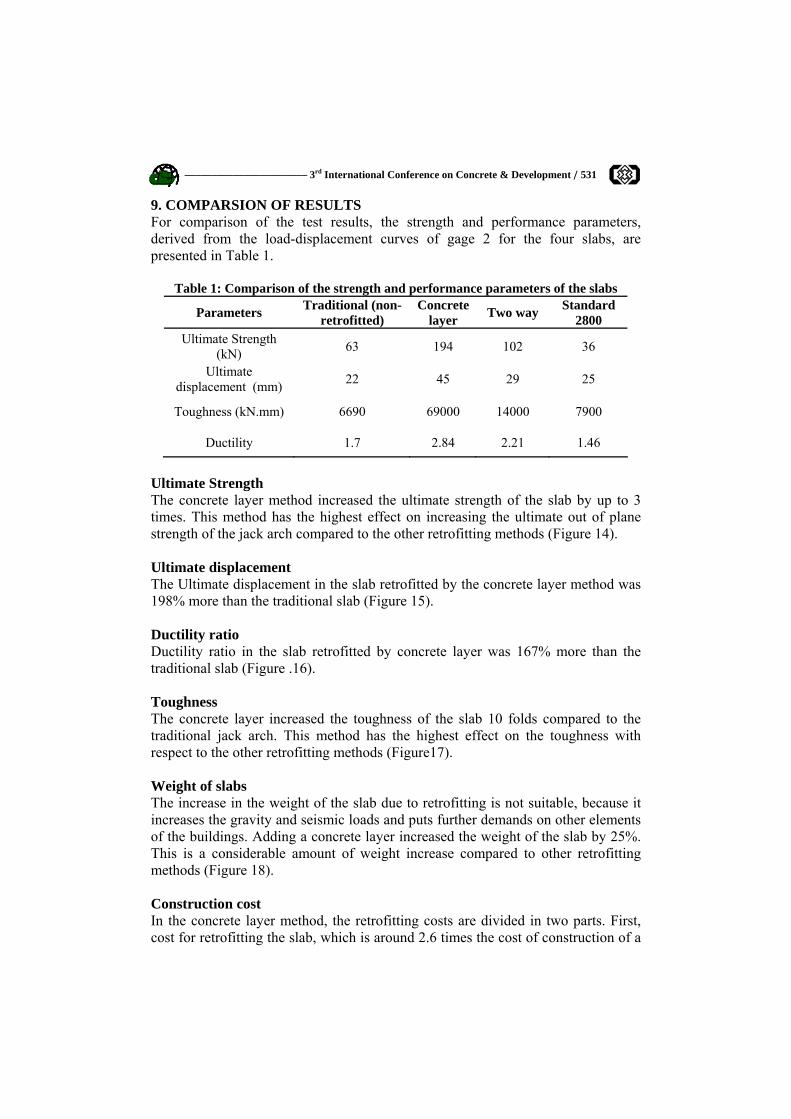
9. COMPARSION OF RESULTS For comparison of the test results, the strength and performance parameters, derived from the load-displacement curves of gage 2 for the four slabs, are presented in Table 1.
Table 1: Comparison of the strength and performance parameters of the slabs
Parameters Traditional (non-retrofitted)
Concrete layer Two way Standard
2800 Ultimate Strength
(kN) 63 194 102 36
Ultimate displacement (mm) 22 45 29 25
Toughness (kN.mm) 6690 69000 14000 7900
Ductility 1.7 2.84 2.21 1.46
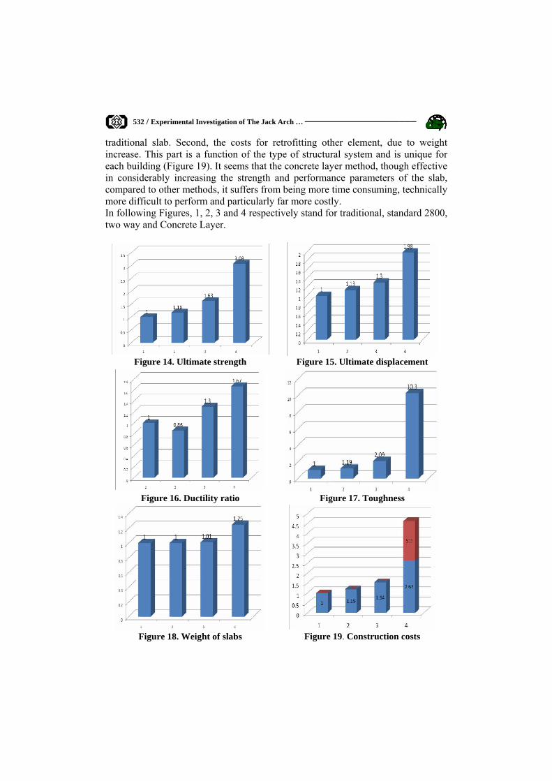
Ultimate Strength The concrete layer method increased the ultimate strength of the slab by up to 3 times. This method has the highest effect on increasing the ultimate out of plane strength of the jack arch compared to the other retrofitting methods (Figure 14). Ultimate displacement The Ultimate displacement in the slab retrofitted by the concrete layer method was 198% more than the traditional slab (Figure 15). Ductility ratio Ductility ratio in the slab retrofitted by concrete layer was 167% more than the traditional slab (Figure .16). Toughness The concrete layer increased the toughness of the slab 10 folds compared to the traditional jack arch. This method has the highest effect on the toughness with respect to the other retrofitting methods (Figure17). Weight of slabs The increase in the weight of the slab due to retrofitting is not suitable, because it increases the gravity and seismic loads and puts further demands on other elements of the buildings. Adding a concrete layer increased the weight of the slab by 25%. This is a considerable amount of weight increase compared to other retrofitting methods (Figure 18). Construction cost In the concrete layer method, the retrofitting costs are divided in two parts. First, cost for retrofitting the slab, which is around 2.6 times the cost of construction of a
532 / Experimental Investigation of The Jack Arch … ––––––––––––––––––––
traditional slab. Second, the costs for retrofitting other element, due to weight increase. This part is a function of the type of structural system and is unique for each building (Figure 19). It seems that the concrete layer method, though effective in considerably increasing the strength and performance parameters of the slab, compared to other methods, it suffers from being more time consuming, technically more difficult to perform and particularly far more costly. In following Figures, 1, 2, 3 and 4 respectively stand for traditional, standard 2800, two way and Concrete Layer.
Figure 18. Weight of slabs Figure 19. Construction costs
––––––––––––––––––––––– 3rd International Conference on Concrete & Development / 533
10. CONCLUSIONS Based on the results of the tests presented in this paper the following conclusions can be drawn regarding the effectiveness of the concrete layer (Romanian) retrofitting method; 1. The method is very effective in increasing the strength and ductility of the jack
arch slab and enhancing its seismic performance. However, it is time consuming and particularly suffers from the excess cost, both in terms of retrofitting the slab itself and the secondary costs of strengthening other elements of the building due to the increased weight.
2. To reduce the secondary costs of the method, it is recommended that after the positioning of the concrete layer, the brick arches be removed, in effect, converting the jack arch slab into a composite steel-concrete slab. However, by doing so, the primary costs of the retrofitting will be increased due to the removal of the brick arches and construction of the necessary false ceiling.
3. Considering the cost-ineffectiveness of the method, it is recommended that it be used to retrofit special buildings or buildings in which due to the overstrength of its members, the secondary cost of retrofitting are minimal.
REFERENCES 1. Razani, R, Lee, K.L., The engineering aspect of the Qir earthquake of April 10.1972
in Southern Iran, National Academy of Engineering, Washington DC, 1973. 2. Maheri, M. R, The engineering aspects of Manjil, Iran earthquake of June
1990, Earthquake engineering. Field investigation team (EEFIT) report, Institute of civil engineers, London, UK. Oct 1990.
3. Maheri, M. R, Lessons from Golbaf, Kerman earthquake of 14 March 1990, Pro. 1st. 4. Iran-Japan workshop on recent earthquake in Iran and Japan, Tehran, pp 319-
330, 1998. 5. Maheri, M. R, Performance of building roofs in the 2003, Bam, Iran,
earthquake, Earthquake Spectra, Vol. 21, No. S1, pp S411-S424, 2005. 6. Moinfar, A. A., Earthquake engineering trend in Iran, Pro. of 3rd World Conf.
on Earthquake. Eng., New Zealand, Vol. 3, 1965. 7. Building and Housing Research Center, Iranian Code of Practice for |Seismic
Resistant Design of Building Standard No 2800, Tehran, 2005, p. 135. 8. Maheri, M. R, Imanipour, A., Seismic evaluation of proposed two way jack
arch slab, Pro. of 3rd Int. Conf. on Seism. and Earthq. Eng., SEE3, Vol. 2, Tehran, Iran, pp. 605-612, 1999.
9. Maheri, M. R, Rahmani, H., Static and seismic design of one way and two way jack arch masonry slabs, J. of Engineering Structures, Vol. 25, No. 13, pp. 1639-1654, 2003.
10. Maheri, M. R, Sesumic Design and Construction of Jack Arch Masonry Slabs, International Institute of Earthquake Engineering and Seismology, Tehran, Iran, 2004.
11. Maheri, M. R, Bahar, O., Analytical studies of the seismic behavior of the I-beam jack arch system, Pro. of 2rd Int. Conf. on Seism. and Earthq. Eng., SEE2, Vol. 1, Tehran, Iran, pp. 819-828, 1995.