EXPERIMENTAL INVESTIGATION OF THE MINIMUM QUANTITY LUBRICATION IN END-MILLING OF AA6061T6 BY COATED CARBIDE TOOLS ABDUL MUHAIMIN BIN ARIS Report submitted in partial fulfillment of requirements for award of the Degree of Bachelor of Mechanical Engineering Faculty of Mechanical Engineering UNIVERSITI MALAYSIA PAHANG JUNE 2013
Transcript
EXPERIMENTAL INVESTIGATION OF THE MINIMUM QUANTITY
LUBRICATION IN END-MILLING OF AA6061T6 BY COATED CARBIDE TOOLS
ABDUL MUHAIMIN BIN ARIS
Report submitted in partial fulfillment of requirements
for award of the Degree of
Bachelor of Mechanical Engineering
Faculty of Mechanical Engineering
UNIVERSITI MALAYSIA PAHANG
JUNE 2013
vii
ABSTRACT
This report presents an experimental investigation on the effects of output
parameters which are surface roughness, tool wear and material removal rate during
machining aluminum alloy 6061-T6 using minimum quantity lubricant (MQL)
technique. The minimum quantity of lubrication technique is becoming increasingly
more popular due to the safety of environment. The cutting speed, depth of cut, feed rate
and MQL flow rate are selected input parameters in this study. This experiment was
conducted based on central composite design method. To develop a model of process
optimization based on the response surface method. MQL parameters include nozzle
direction in relation to feed direction, nozzle elevation angle, distance from the nozzle
tip to the cutting zone, lubricant flow rate and air pressure. To achieve a maximum
output parameters based on the optimized process parameters for coated carbide cutting
tools (CTP 2235). The surface roughness was increased with decrease of cutting speed.
The optimum cutting condition for MQL and flooded are obtained the feed rate, depth
of cut, cutting speed and MQL flow rate are 379 mm/tooth, 2 mm, 5548.258 rpm and
0.333 ml/min respectively for MQL. The optimum cutting condition for flooded are
obtained the feed rate, depth of cut, cutting speed and MQL flow rate are 379 mm/tooth,
2 mm and 5563.299 rpm respectively for flooded. It is seen that a majority of coated
carbide inserts have a long tool wear when exposed to high cutting speed, and feed rate
leading to breakage of the inserts.
viii
ABSTRAK
Laporan ini membentangkan siasatan ujikaji mengenai kesan parameter
pengeluar iaitu kekasaran permukaan, pemakaian alat dan kadar penyingkiran bahan
semasa pemesinan aloi aluminium 6061-T6 menggunakan minimum kuantiti pelincir
(MQL) teknik. Teknik minimum kuantiti pelinciran menjadi semakin popular kerana
keselamatan alam sekitar. Kelajuan pemotongan, kedalaman pemotongan, ‘feed rate’
dan kadar aliran MQL dipilih menjadi parameter kemasukan dalam kajian ini.
Eksperimen ini telah dijalankan berdasarkan reka bentuk komposit pusat kaedah. Untuk
membentuk model pengoptimuman berdasarkan kaedah gerak balas permukaan.
Parameter MQL termasuk arah muncung berhubung dengan makanan haiwan arah,
sudut ketinggian jarak muncung dari hujung muncung ke zon pemotongan, kadar aliran
pelincir dan tekanan udara. Untuk mencapai parameter pengeluar maksimum
berdasarkan proses parameter dioptimumkan untuk bersalut alat pemotong karbida
(CTP 2235). Kekasaran permukaan telah meningkat dengan penurunan kelajuan
pemotongan. Keadaan pemotongan optimum untuk MQL dan ‘flooded’ diperolehi ‘feed
rate’, kedalaman potongan, kelajuan pemotongan dan kadar aliran MQL adalah 379
mm/gigi, 2 mm, 5548,258 rpm dan 0.333 ml/min masing-masing untuk MQL. Keadaan
pemotongan optimum untuk ‘flooded’ diperolehi ‘feed rate’, kedalaman potongan,
kelajuan pemotongan dan kadar aliran MQL adalah 379 mm/gigi, 2 mm dan 5563,299
rpm masing-masing untuk ‘flooded’. Ia dilihat bahawa majoriti ‘insert’ bersalut karbida
mempunyai pemakaian alat yang lama apabila terdedah kepada kelajuan pemotongan
yang tinggi, dan ‘feed rate’ yang membawa kepada kerosakan kepada ‘inserts’.
ix
TABLE OF CONTENTS
Page
EXAMINER’S DECLARATION ii
SUPERVISOR’S DECLARATION iii
STUDENT’S DECLARATION v
ACKNOWLEDGEMENTS vi
ABSTRACT vii
ABSTRAK viii
TABLE OF CONTENTS ix
LIST OF TABLES xii
LIST OF FIGURES xiii
LIST OF SYMBOLS xv
LIST OF ABBREVIATIONS xvi
CHAPTER 1 INTRODUCTION
1.1 Introduction 1
1.2 Problem Statement 2
1.3 Objectives of the project 3
1.4 Project scope 3
1.5 Organization of the project 4
CHAPTER 2 LITERATURE REVIEW
2.1 Introduction 5
2.2 Milling Machine 5
2.2.1 Type of Milling Machine 6
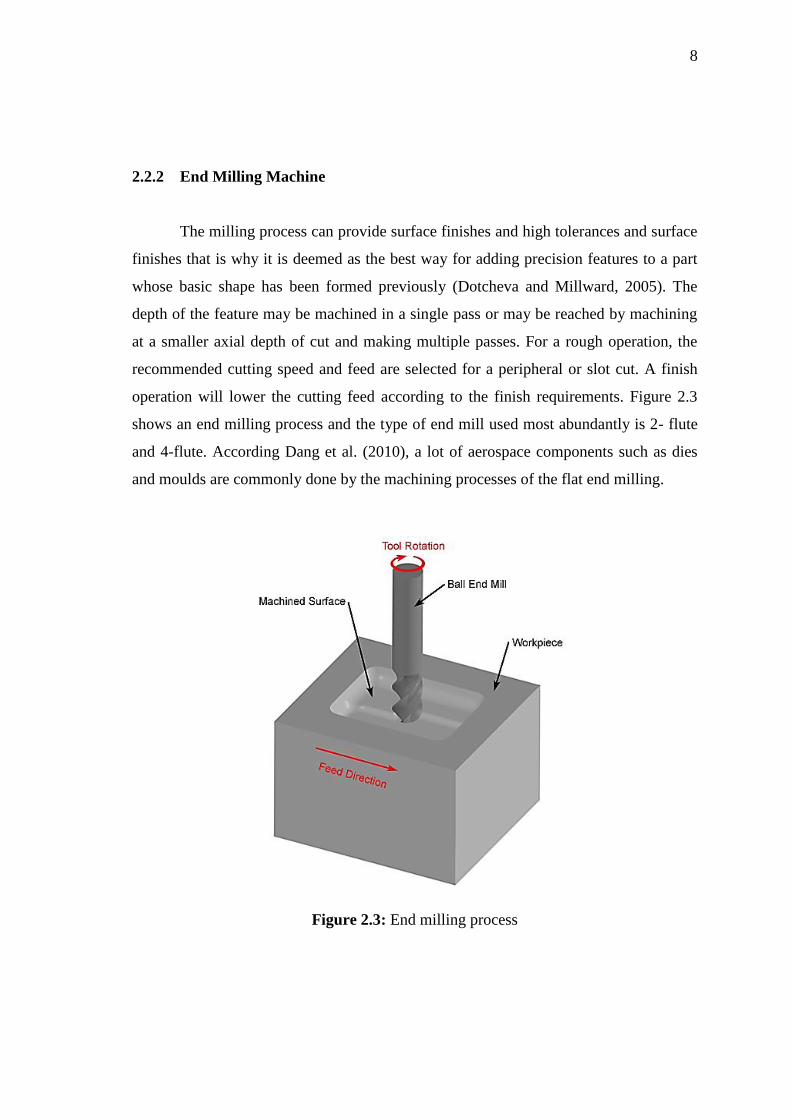
2.2.2 End Milling Machine 8
2.2.3 Operation of Milling Machine 9
2.3 Coated Carbide Tools 9
2.4 Minimum Quantity Lubrication 10
2.5 Aluminum Alloy 11
x
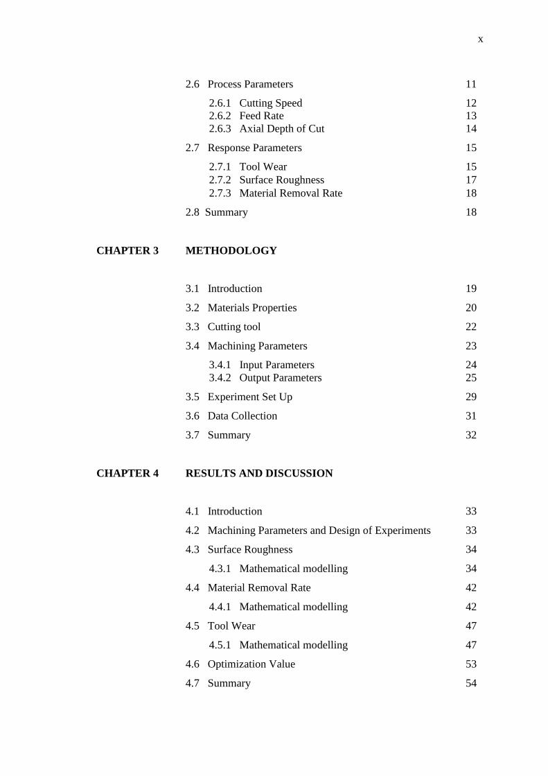
2.6 Process Parameters 11
2.6.1 Cutting Speed 12
2.6.2 Feed Rate 13
2.6.3 Axial Depth of Cut 14
2.7 Response Parameters 15
2.7.1 Tool Wear 15
2.7.2 Surface Roughness 17
2.7.3 Material Removal Rate 18
2.8 Summary 18
CHAPTER 3 METHODOLOGY
3.1 Introduction 19
3.2 Materials Properties 20
3.3 Cutting tool 22
3.4 Machining Parameters 23
3.4.1 Input Parameters 24
3.4.2 Output Parameters 25
3.5 Experiment Set Up 29
3.6 Data Collection 31
3.7 Summary 32
CHAPTER 4 RESULTS AND DISCUSSION
4.1 Introduction 33
4.2 Machining Parameters and Design of Experiments 33
4.3 Surface Roughness 34
4.3.1 Mathematical modelling 34
4.4 Material Removal Rate 42
4.4.1 Mathematical modelling 42
4.5 Tool Wear 47
4.5.1 Mathematical modelling 47
4.6 Optimization Value 53
4.7 Summary 54
xi
CHAPTER 5 CONCLUSION AND RECOMMENDATIONS
5.1 Introduction 55
5.2 Conclusion 55
5.3 Recommendations 56
REFERENCES 57
xii
LIST OF TABLES
Table No. Title Page
3.1 Chemical composition of the aluminum alloy 6061-T6 21
3.2 Composition of the coated carbide inserts 22
3.3 Parameters for MQL Machining. 23
3.4 Input and output parameters 24
3.5 The specification for CNC milling machine HAAS VF-6 30
4.1 Design of Experiment Matrix for MQL 34
4.2 Design of Experiment Matrix for flooded 34
4.3 Variance analysis for the second order model of the surface roughness
MQL and flooded
36
4.4 Experimental and predicted results second order model RSM of surface
roughness for MQL
37
4.5 Experimental and predicted results second order model RSM of surface
roughness for flooded
38
4.6 Variance analysis for second orders MRR for MQL and flooded 43
4.7 Experimental results RSM second order material removal rate predicted
values for flooded
45
4.8 Experimental results RSM second order material removal rate predicted
values for MQL
46
4.9 Variance analysis for second orders tool wear for MQL and flooded 48
4.10
Experimental and predicted results second order model RSM of tool wear
for flooded
49
4.11 Experimental and predicted results second order model RSM of tool wear
for MQL
51
4.12 The optimization of MQL and flooded for coated carbide inserts 53
xiii
LIST OF FIGURES
Figure No. Title Page
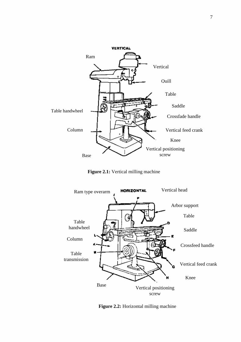
2.1 Vertical milling machine 7
2.2 Horizontal milling machine 7
2.3 End milling process 8
2.4 Different operation of miling machine 9
2.5 End milling (Milling machine) operation. 15
2.6 The comparison of the tool wear for different cutting processes 16
3.1 Flow chart of the study 20
3.2 Workpiece block. 21
3.3 Tool holder and cutting tool insert and insert coated carbide tool 25
3.4 Graph position for average roughness (Ra) 26
3.5 Tool wear depend on the technique use. 26
3.6 The movement of tool in horizontal milling machine. 28
3.7 The movement of tool in vertical milling machine. 29
3.8 CNC milling machine HAAS VF-6 29
3.9 Portable roughness tester model MarSurf PS1 31
3.10 Optical video measuring system 32
4.1 Image of surface roughness for maximum cutting speed MQL and
flooded
38
4.2 Image of surface roughness for maximum feed rate MQL and flooded 39
4.3 Image of surface roughness for maximum depth of cut MQL and
flooded
39
4.4 Surface roughness versus MQL 40
4.5 Surface roughness versus feed rate using (a) MQL (b) flooded 41
xiv
4.6 Surface roughness versus depth of cut for (a) MQL (b) flooded 41
4.7 Surface roughness versus cutting speed for (a) MQL (b) flooded 42
4.8 MRR versus depth of cut for (a) MQL (b) flooded 44
4.9 MRR versus feed rate for (a) MQL (b) flooded 46
4.10 MRR versus cutting speed for MQL (b) flooded 47
4.11 Image of tool wear (a) MQL (b) flooded 50
4.12 Tool wear versus MQL flow rate 50
4.13 Tool wear versus feed rate for (a) MQL (b) flooded 52
4.14 Tool wear versus depth of cut for (a) MQL (b) flooded 52
4.15 Tool wear versus cutting speed for (a) MQL (b) flooded 53
xv
LIST OF SYMBOLS
RPM Revolution per minute
vc cutting speed
rf feed rate in mm/rev
ft Feed rate in mm/tooth
n Number of the teeth of cutter
Ra Average surface roughness
L Sampling length
Y Ordinate of the profile curve
V Cutting speed
T Tool life (minutes)
C Taylor’s constant for the unaccounted variables
N RPM of Cutter
W Width of cut (may be full cutter or partial cutter)
t Depth of cut
L Length of pass or cut
fm Table (machine) Feed
D Cutter Diameter in mm
xvi
LIST OF ABBREVIATIONS
MQL Minimum quantity lubrication
RSM Response surface method
CNC Computer numerical control
TiC Titanium carbide
TiCN Titanium carbon nitride
TiN Titanium nitride
PVD Physical vapour deposition
CVD Chemical vapor deposition
NDM Near dry machining
DOE Design of Experiment
RPM Revolution per minute
CBN Cubic boron nitride
GF Green factor
ISO International standard organization
HSS High Speed Steel
CLA Center Line Average
AA Arithmetic Average
Ra Average roughness
MRR Material Removal Rate
CS Cutting speed
SR Surface roughness
1
CHAPTER 1
INTRODUCTION
1.1 INTRODUCTION
Manufacturing usually occurs in large scale that involves mass of production.
Beside the manufacturers in the competitive marketplace because of the manufacturing
environment, low costs, goals of high rates of production, and high quality. The
minimization of cutting fluid also leads to economic benefits by way of saving lubricant
costs and workpiece/tool/machine cleaning cycle time (Dhar et al., 2006). In order to
improve the traditional manufacturing, many technologies are developed and it causes
many machines have been created as well as the tools themselves. There are many types
of machine and tools that are used to process the material in manufacturing process.
Some of them may involve high cost to operate the process such as cost of machine,
cost of maintainence, energy consumption, labor and so on. Therefore, in mass
production, it is important to consider the economic aspect in order to make the industry
profitable and growth. Many traditional techniques and hybrid methodologies have been
developed to make the manufacturing process more effective such as directly assess the
machining performance (Jawahir et al., 2003).
Machining process require specific cutting tools to be used in order to obtain
optimum machining performance. We can use high quality of material to create better
tool for example by using TiN-coated carbide cutting tool as it can stand at high
temperature, high cutting-speed and it was prove that can improve the tool life. The
coated tools are used more than 40 % in industry and perform more than 80 % to all
machining (Cselle and Barimani, 1995). However, the performance of that cutting tool
is depending on many variable of cutting conditions.
2
This project focused on the technique to apply MQL performed in machining
AA6061-T6 using coated carbide tool and CNC end milling machine. The mechanical
properties for AA6061-T6 depend greatly on the temper, heat treatment, of the material.
The aluminum offers advantages over other materials because of its relatively low
density, high recyclability, design flexibility in mass production and economic benefit
(Chu and Xu, 2004). Besides that, the aluminum is getting more popular due to
increasing concern in fuel economy and stringent government emission regulations,
lightweight materials Aluminum are also being extensively adopted by design engineers
for structural components. Surface finish is essential factor in evaluating the quality of
products and average surface roughness (Ra) most is common index used to determine
the surface finish. The response surface method (RSM) as a statistical method that been
used to optimize the surface responses. The RSM quantifies the relationship between
response surfaces and input parameters. Fuh and Hwang (1997) constructed a model
that can predict the milling force in end milling operations by using RSM method. They
measured the speed of spindle rotation, feed per tooth and axial and radial depth of cut
as the three major factors that affect in milling operation. The comparison between the
experimental data and the values predicted by this prediction model showed the model’s
accuracy to be as high as 95 %. In this experiment focuses on best usage of machining
AA6061-T6 and coated carbide in respect to the cutting force, tool life and surface
roughness using the RSM approaches in the CNC milling machine.
1.2 PROBLEM STATEMENT
Performances of milling machine almost depend highly on how fast the machine
can cut the work piece. Ulutan and Ozel (2011) mentioned that the accuracy of
workpiece dimension, tool wear, surface finish, and tool life on the MRR and cutting
tool have increased for enhancing the product performance in relation to the impact of
the environment. High productivity needs high rate of metal removal, so it can reduce
manufacturing cost and operation time. The large amount of the cutting fluid used in
machining is damaging and environmentally harmful become it may contain damaging
chemical elements which is dangerous to the skin and lung of the operators plus it can
couse air pollution (Sreejith, 2008). The minimal quantity lubrication will be used in our
experimental will be compare with another cutting fluid. MQL in an end-milling
3
process is very much effective regarding (Lopez de Lacalle et al., 2004) and they
mentioned that MQL can reach the tool face more easily in milling operations compared
with other cutting operations. AA6061-T6 is more suitable choice due to its cost-
efficient element (MacMaster et al., 2000) and economical aspect has always been
important when it comes to mass production while there is more material such as
aluminum alloy AA 6069 (Chu and Xu, 2004). Ghani et al. (2004a) investigated that the
coating typically reduced the coefficient of friction between the cutting tools and reduce
the tool wear. Eventually, sudden failure of cutting tools lead to loss of productivity,
rejection of parts and consequential economic losses. The coated carbide tool is to be
considered in this study to evaluate the performance of a machining process depends on
tool wear or tool life.
1.3 OBJECTIVE OF THE PROJECT
The objectives of this project are as follows:
i. To experimentally investigate the machining characteristics of aluminum alloy
in end mill processes for flooded and MQL techniques.
ii. To investigate surface quality finish of coated carbide cutting tool by using
MQL method.
iii. To study the tool wear and the material removal rate regarding the MQL
technique.
1.4 PROJECT SCOPE
i. Using CNC milling machine to operate the end milling on AA6061T6 by coated
carbide using MQL.
ii. Determine optimum performance of coated carbide cutting tools in milling
operation by vary machining parameter which is cutting speed, feed and depth of
cut.
iii. Design of experiments and Optimization model develop are prepared using
MiniTab software.
iv. Mathematical model used response surface method.
4
1.5 ORGANIZATION OF REPORT
There are five chapters including introduction chapter in this study. Chapter 2
presents the literature review of previous studies includes the end milling, process