AD TECHNICAL REPORT 9122 EXPERIMENTAL METHOD FOR DETERMINATION OF THE RATE OF EVAPORATION OF 2,4,6-TRINITROTOLUENE (TNT) AND 2,4-DINITROTOLUENE (2,4-DNT) ALAN B. ROSENCRANCE ERNST E. BRUEGGEMANN _ DTIC L ELECTE : - AUG4 199313 (0 U U S ARMY BIOMEDICAL RESEARCH & DEVELOPMENT LABORATORY Fort Detrck Frederick, MD 21702-5010 June 1993 Approved for public release; distribution unlimited. 93-17407 1111 ill Ml~ 1 l IIuhl f hll J ilhhil IlfJ li!1 . •r U S ARMY MEDICAL RESEARCH & DEVELOPMENT COMMAND Fort Detrick Fdeick,MD 21702-5012 •3 8 30 2
Transcript
AD
TECHNICAL REPORT 9122
EXPERIMENTAL METHOD FOR DETERMINATION OF THE RATE OFEVAPORATION OF 2,4,6-TRINITROTOLUENE (TNT) AND 2,4-DINITROTOLUENE (2,4-DNT)
ALAN B. ROSENCRANCE
ERNST E. BRUEGGEMANN
_ DTICL ELECTE :
- AUG4 199313
(0 U
U S ARMY BIOMEDICAL RESEARCH & DEVELOPMENT LABORATORY
Fort Detrck
Frederick, MD 21702-5010
June 1993
Approved for public release;distribution unlimited.
93-174071111 ill Ml~ 1 l II uhl f hll J ilhhil IlfJ li!1 . •r
U S ARMY MEDICAL RESEARCH & DEVELOPMENT COMMANDFort DetrickFdeick,MD 21702-5012 •3 8 30 2
UNCLASSIFIEDUNCLASSIFIEDSECURITY CLASSIFICATION OF THIS PAGE
Form ApprovedREPORT DOCUMENTATION PAGE OMB No. 0704-0188
Unclassified2a. SECURITY CLASSIFICATION AUTHORITY 3 DISTRIBUTION /AVAILABILITY OF REPORT
Approved for public release; distribution2b. DECLASSIFICATION /DOWNGRADING SCHEDULE unlimited
4. PERFORMING ORGANIZATION REPORT NUMBER(S) S. MONITORING ORGANIZATION REPORT NUMBER(S)
Technical Report Number 9122
6a. NAME OF PERFORMING ORGANIZATION 6b. OFFICE SYMBOL 7a. NAME OF MONITORING ORGANIZATIONU.S. Army Biomedical Research (if applicable)and Development Laboratory SGRD-UBG-R
6c. ADDRESS (City, State, and ZIP Code) 7b. ADDRESS (City, State, and ZIP Code)Fort DetrickFrederick, MD 21702-5010
Ba. NAME OF FUNDING/SPONSORING 8b OFFICE SYMBOL 9. PROCUREMENT INSTRUMENT IDENTIFICATION NUMBERORGANIZATION U.S. Army Biomedic c (If applicable)
Research and Development Lab SGRD-UBG-R8c. ADDRESS (City, State, and ZIP Code) 10. SOURCE OF FUNDING NUMBERS
Fort Detrick PROGRAM PROJECJT TASK WORK UNIT
Frederick, MD 21702-5010 ELEMENT NO. NO. 3M1611 NO. ACCESSION NO.0601102A 02BS15 CC 010 F211
11 TITLE (Include Security Classification)Experimental Method for Determination of the Rate of Evaporation of 2,4,6-Trinitrotoluene(TNT) and 2,4-Dinitrotoluene (2,4-DNT)
12. PERSONAL AUTHOR(S)
Alan B. Rosencrance, Ernst E. Brue emann13a. TYPE OF REPORT 13b. TIME COVERED 14 DATE OF REPORT (Year, Month, Day) 15. PAGE COUNT
Technical FROM Jul 90 TO Jun 93 1993, June 2016. SUPPLEMENTARY NOTATION
17 COSATI CODES 18 SUBJECT TERMS (Continue on reverse if necessary and identify by block number)
FIELD GROUP I SUB-GROUP High Performance Liquid Chromatograph (HPLC), 2,4,6-Trinitro-U/ 04 toluene (TNT), 2-4-Dinitrotoluene (2,4-DNT), Explosives,
Rate of Evaporation19. ABSTRACT (Continue on reverse if necessary and identify by block number)
The rate of evaporation of 1,3,5-trinitrotoluene (TNT) and 2,4-dinitrotoluene (DNT)into air under ambient conditions was determined. This was accomplished by making cast pipesof TNT and 2,4-DNT. Nitrogen was passed through a pipe and then through a cold trap. Thetrap contained 0.5 mL of methanol and was chilled in an ice bath. The nitrogen flow rate(mL/min) through the pipe and trap was measured and after a specified amount of time the trapwas disconnected and the methanol was removed. The concentration of TNT or 2,4-DNT in themethanol was determined by high performance liquid chromatography (HPLC) analysis. From themass of TNT or 2,4-DNT found, mean flow rate of nitrogen through the apparatus, and thelength_?f tiijTe for a run, the rate of evaporation as grams per minute per square centimeter(g min cm" ) was calculated. This data was used to validate Griffy's theoretical model fordetermining the evaporation rate of TNT.
20 DISTRIBUTION /AVAILABILITY OF ABSTRACT 21 ABSTRACT SECURITY CLASSIFICATION
[3 UNCLASSIFIED/UNLIMITED 0 SAME AS RPT ' DTIC USERS Unclassified22a. NAME OF RESPONSIBLE INDIVIDUAL 22b TELEPHONE (Include Area Code) 22c OFFICE SYMBOL
Alan B. Rosencrance 301-619-2340 SGRD-UBG-R
DO Form 1473, JUN 86 Previous editions are obsolete SE(tuRITY CLASSIFICATION OF THIS PAGE
UNCLASSI FIED UNCLASSIFIED
NOTICE
Disclaimer
The views, opinions, and/or findings contained in this report are thoseof the authors(s) and should not be construed as official Department the Armyposition, policy, or decision, unless so designated by other officialdocumentation.
Disposition
Destroy this report when it is no longer needed. Do not return it to theoriginator.
TiS CPA&I
; 1IlC TAB',ia', ,o :,,"pdl [
J ,S'rifj,- I:
ByU I stV ib u ionl
A-Viability CodeS
DTIC QUAITY IN8PE,(JTEI 3AiL . .. . . . .. . .
TABLE OF CONTENTS
Page
INTRODUCTION AND OBJECTIVES ............................................... 1
METHODS AND MATERIALS ..................................................... 1
Chemicals ............................................ 1...High Performance Liquid Chromatographic (HPLC) Analysis .............. 1Method for Measurement of Rate of Evaporation ........................ 2
6. PLOT OF RATE OF EVAPORATION OF TNT VERSUS REYNOLDS NUMBER ............ 13
7. PLOT OF RATE OF EVAPORATION OF 2,4-DNT VERSUS REYNOLDS NUMBER ........ 14
INTRODUCTION AND OBJECTIVES
According to our literature search the rate of evaporation of2,4,6-trinitrotoluene (TNT) or 2,4-dinitrotoluene (DNT) has never beenmeasured. Although the scientific literature does present measurements of theequilibrium vapor pressure of TNT 1 '2 .3 these data have little use for describingthe levels of TNT in air in actual scenarios.
In the real world, the TNT source (cm 2) is small and the reservoir intowhich it is released (cm 3) is large and is perturbed by ventilation. Forthese reasons, equilibrium vapor pressure has no application. If the rate ofevaporation into air were known (g min-' cm"2) the actual concentration of TNTin air could be estimated. This problem was addressed by Griffy4 in modelingthe TNT vapor for bomb detection. His description required the evaporationrate to estimate TNT concentration in air in a closed space.
Besides filling a gap in the literature that was long ignored, theempirical measurement of evaporation rate (g min` cM"2) will be of use inestimating exposure levels to workers in the manufacture of TNT and DNT andcontribute to validation of the model described by Griffy4 for detection ofvapors from concealed expolsives.
It was our objective to empirically measure the rate of evaporation ofTNT and ONT into air under ambient conditions of air flow and temperature.
METHODS AND MATERIALS
CHEMICALS
Crude TNT was obtained from Volunteer Army Ammunition Plant, Tyner,Tennessee and purified by recrystallization from methanol, then hexane. The2,4-DNT for this study was purchased from Aldrich Chemical Company, Inc.(Milwaukee, WI) and was purified by recrystallization from hexane. Allsolvents used for recrystallization and HPLC analysis were from Burdick andJackson Laboratories (Division of Baxter Healthcare Corp., Columbia, MD).
HIGH PERFORMANCE LIQUID CHROMATOGRAPHIC (HPLC) ANALYSIS
The HPLC method employed was a simplification of a procedure published byBrueggemann5 . The method was simplified by using an isocratic mobile phasebecause the samples contained few if any background interferences. Theisocratic mobile phase provided adequate resolution of all the compounds ofinterest.
A liquid chromatographic system (Waters Chromatography Division,Millipore, Milford, MA) was used throughout the study. The system consistedof the following components: a model 6000A solvent delivery system, a model721 programmable system controller, a model 730 data module, and a model 710BWISP autosampler. The UV detector was a spectroflow 783 programmableabsorbance detector (Kratos Analytical Instruments, Ramsey, NJ).
I
Separation of the explosives was achieved with a ZorbaxTM ODS column(25cm x 4.6mm i.d., DuPont Instruments Co., Wilmington, DE). An isocraticmobile phase (60 percent methanol/water) was employed at a flow rate of 1.0mL/min. The column effluent was monitored at 254 nm, 0.002 absorbance unitsfull scale. The injection volume was 25 microliters.
METHOD FOR MEASUREMENT OF RATE OF EVAPORATION
The experimental method to measure the rate of evaporation consists ofpassing air at constant velocity across a measured surface of explosive atconstant temperature. The explosive from the air is trapped in a solvent trapand its mass is measured.
The surface consisted of the inner wall of a pipe of cast explosive thatis shown in Figure 1. The hollow cylinder of explosive is made by pouringmolten TNT or 2 4-DNT into the annulus formed by a glass tube and a smaller,straight TeflonTM (PTFE) tube inserted along the center of the glass tube.The explosives were individually melted in a steam bath and individuallypoured into separate molds. When the explosives had cooled and solidified,the TeflonTM tube was gently withdrawn to create a hole of known diameterinside of a cylinder of solid 2,4-DNT or TNT. The case material is supportedby the outer glass tube. Into each end of this pipe is inserted a short pieceof the same PTFE tubing that was used to create the hole in the cylinder.These tubes form a tight connection and allow nitrogen to pass from a sourceof compressed nitrogen, through the pipe and then through a cold trap. Tomaintain a snug fit of the inlet and outlet tubes, each tube is inserted I cminto the pipe and this point of connection wrapped tightly with ParaFilmTM inorder to prevent any leakage. As nitrogen moves between the inlet and outlet,it encounters a smooth surface of 2,4-DNT or TNT of known area. The effluentfrom the cast pipe passes through a glass trap fabricated from a 3-mL pipetteshown in Figure 2. The trap contained 0.5 mL of methanol and was chilled inan ice bath. Preliminary experiments showed that a dry cold trap was not aseffective as a cold trap containing methanol. To ensure that all of theeffluent vapor was trapped, some experiments were carried out with two trapsconnected in series. From these experiments it was determined that a singletrap was sufficient for collecting the vapors at most flow rates. The flowrate (mL/min) of nitrogen through the cast pipe and into the trap wasmonitored periodically during each run by a GilibratorTM model electronicbubble flowmeter (Gilian Instrument Corp., West Caldwell, NJ) connected to theoutlet of the trap. After a measured time, the trap was disconnected and themethanol in the trap removed. The trap was rinsed twice with more methanoland the solution and rinses combined in a single vial. The amount of methanolwas determined gravimetrically in order to obtain a better estimate of thesample volume. The concentration of TNT or 2,4-DNT in the methanol wasdetermined by HPLC analysis. From the mass of TNT or 2,4-ONT found, mean flowrate of nitrogen through the apparatus and the length of time for a run, therate of evaporation as grams per minute per square centimeter (g min-' cm2 )could be calculated.
2
A SPACE
CROSSECTION
SiTNT
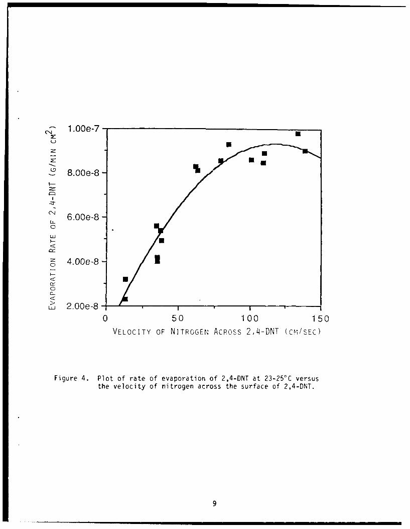
Figure 1. Cross section and side view of cylinder cast from molten TNTor 2,4-DNT. The inner surface serves as a measured area forevaporation and has an internal diameter of 0.4 cm.
3
Figure 2. Drawing of the trap fabricated from a 3-mL pipette. This held0.5 mL of methanol and was chilled in an ice bath. Theeffluent from the evaporatin source entered through the bluntend via a 2-cm piece of PTFETM tubing and bubbled through thecold methanol while depositing the TNT or'2,4-DNT. The tip ofthe pipette-trap was connected via a TygonTM tube to aGilibratorTM model flow meter to determine the flow rate ofnitrogen through the source.
4
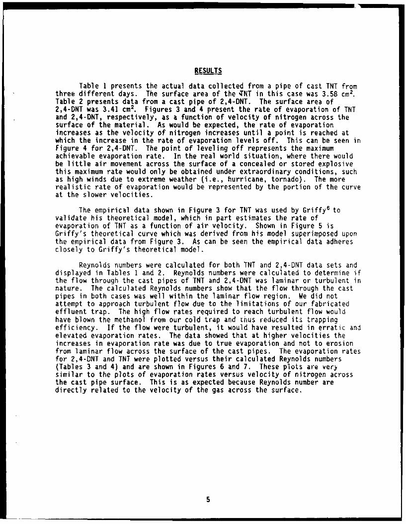
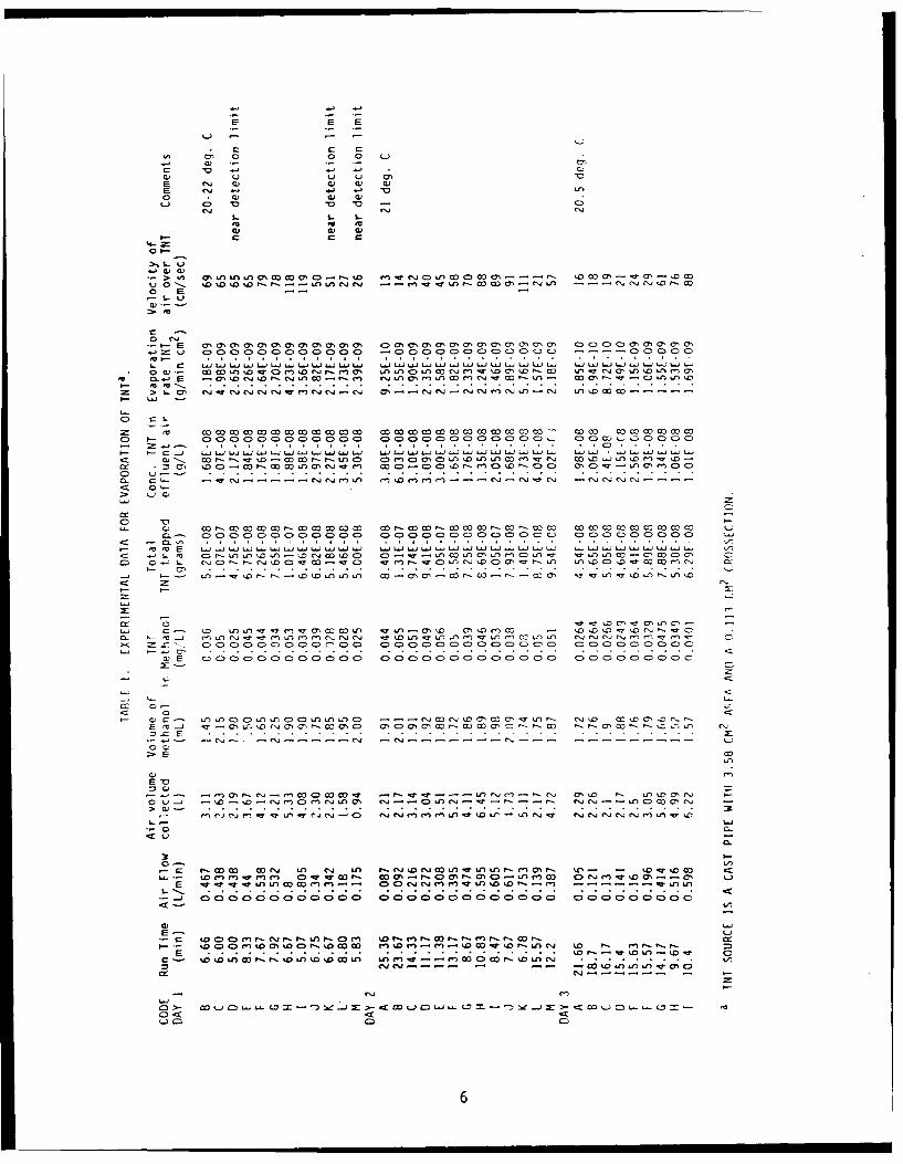
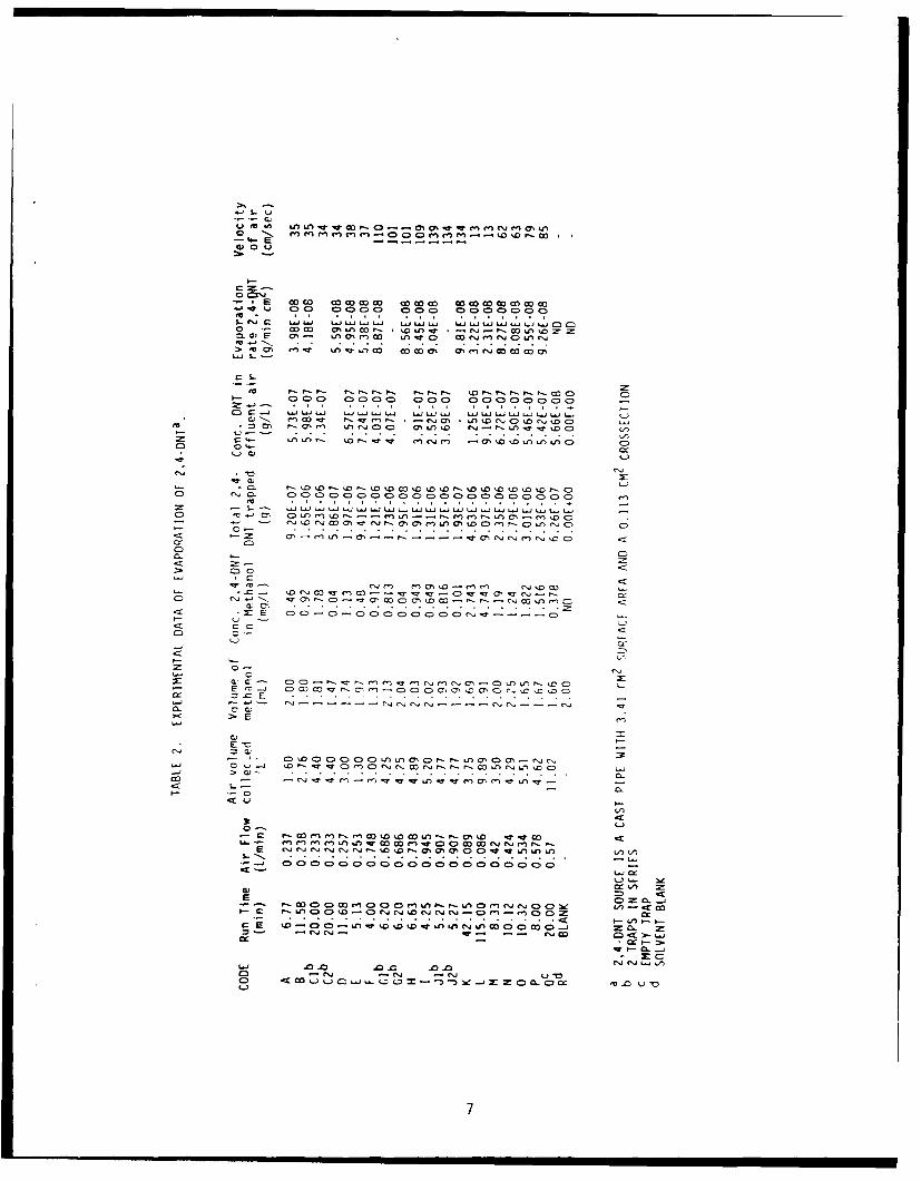
RESULTS
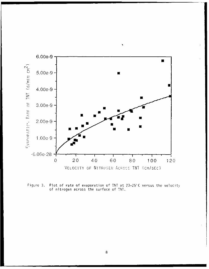
Table 1 presents the actual data collected from a pipe of cast TNT fromthree different days. The surface area of the %NT in this case was 3.58 cm2.Table 2 presents data from a cast pipe of 2,4-DNT. The surface area of2,4-DNT was 3.41 cm2. Figures 3 and 4 present the rate of evaporation of TNTand 2,4-DNT, respectively, as a function of velocity of nitrogen across thesurface of the material. As would be expected, the rate of evaporationincreases as the velocity of nitrogen increases until a point is reached atwhich the increase in the rate of evaporation levels off. This can be seen inFigure 4 for 2,4-DNT. The point of leveling off represents the maximumachievable evaporation rate. In the real world situation, where there wouldbe little air movement across the surface of a concealed or stored explosivethis maximum rate would only be obtained under extraordinary conditions, suchas high winds due to extreme weather (i.e., hurricane, tornado). The morerealistic rate of evaporation would be represented by the portion of the curveat the slower velocities.
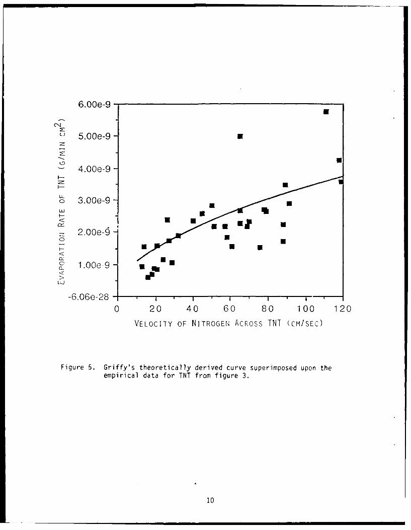
The empirical data shown in Figure 3 for TNT was used by Griffy6 tovalidate his theoretical model, which in part estimates the rate ofevaporation of TNT as a function of air velocity. Shown in Figure 5 isGriffy's theoretical curve which was derived from his model superimposed uponthe empirical data from Figure 3. As can be seen the empirical data adheresclosely to Griffy's theoretical model.
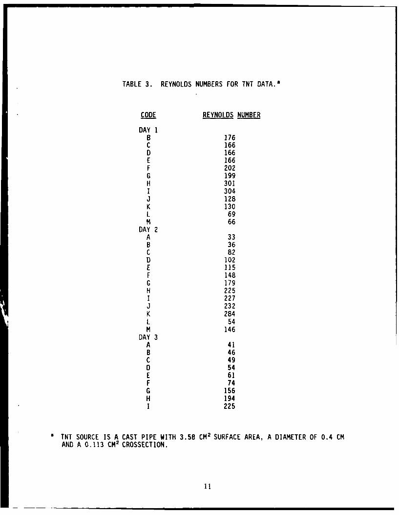
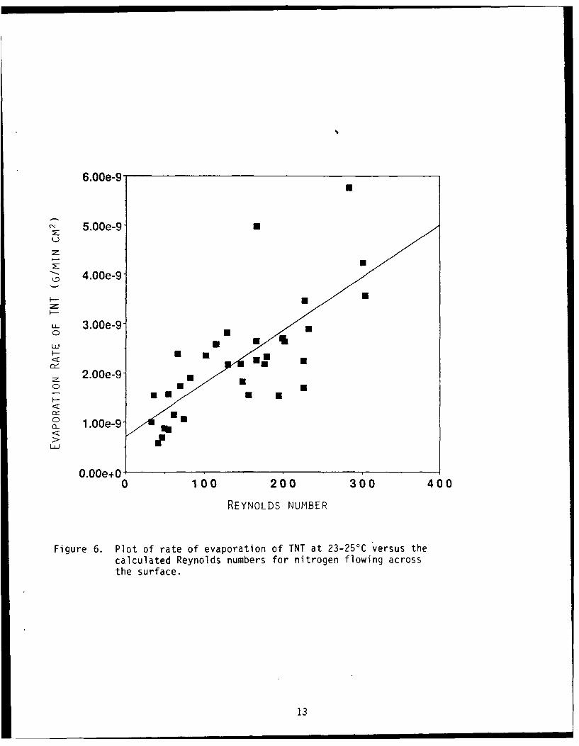
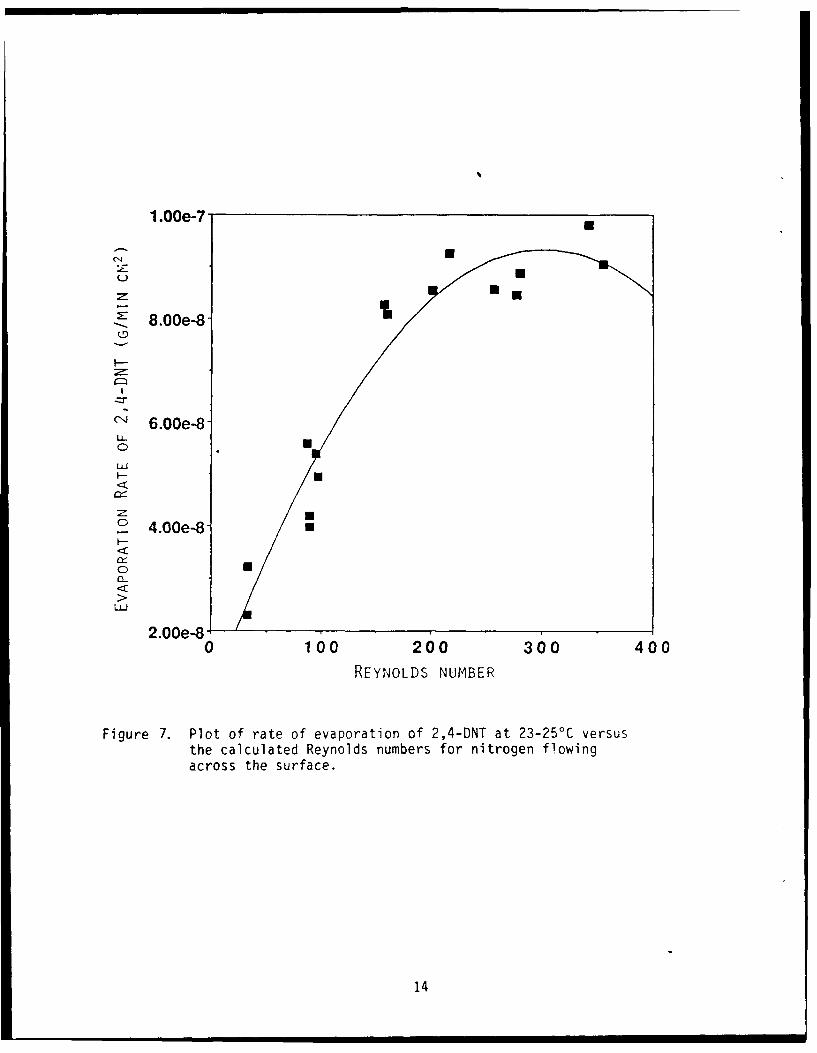
Reynolds numbers were calculated for both TNT and 2,4-DNT data sets anddisplayed in Tables 1 and 2. Reynolds numbers were calculated to determine ifthe flow through the cast pipes of TNT and 2,4-DNT was laminar or turbulent innature. The calculated Reynolds numbers show that the flow through the castpipes in both cases was well within the laminar flow region. We did notattempt to approach turbulent flow due to the limitations of our fabricatedeffluent trap. The high flow rates required to reach turbulent flow wouldhave blown the methanol from our cold trap and Lhus reduced its trappingefficiency. If the flow were turbulent, it would have resulted in erratic andelevated evaporation rates. The data showed that at higher velocities theincreases in evaporation rate was due to true evaporation and not to erosionfrom laminar flow across the surface of the cast pipes. The evaporation ratesfor 2,4-DNT and TNT were plotted versus their calculated Reynolds numbers(Tables 3 and 4) and are shown in Figures 6 and 7. These plots are verýsimilar to the plots of evaporation rates versus velocity of nitrogen acrossthe cast pipe surface. This is as expected because Reynolds number aredirectly related to the velocity of the gas across the surface.
5
w, ..
a) C) u- v
E (NJ C) 4) (V (DE CN -. ~ ~Lno- 4D 'V 'a
L) E
o I-E a, al(1C ,V %C %O lUOCCaal a ,c II, c D Da ,a ,CuiC)C
o -W - -rMO jMCjL -c n1 o0
C)..-ww wM =W.O cowwwwc (wwc ucoCP ow0
ox ý1 M c D a C) LnC m ~ A CD
0- cý.-- .- - ! --CLZ w CJML en L. 0) mNJ J(Jn.N C'(N(l(NJ AJ LA cjc. c.
o ; CLo= om
o C:- cýo c'o oo o Io 0 00 0~ cOC 0 0 0 ý ý c ý ýc c ý
>n , ' )> 0
C) c .0c o 00c
It -C.C'-1 ,LnC- i vC) )U)U)U)U)U. s . s s . Us) Us) Us) 'a) -r M. Us) U) Cc) W. U) U) U.) Ua) Us) a,) U) U.) co Us) ID UD 10 J
1) 11).( In IA-5lnJ5l 0~ LA L 0)A70 A ýD LALA.C.-C)CI.0C) rJ
, n- r 0C 0D C~~ U, - -)U .. ) C C-C.D nL (C C r(ý)CCU COA-.O aCco
C><r ' ýq C 0 ) 0C, C'. O C, C) L Cc coco C, '0 In00 00
- L: L
~C:)
CV)
-- 5--- f) - -w men o a - - - - - - -m--.c 11, 1. CoO. t-.o Li~~C -. NJ))L O PN0L- - -- N 40L 0~) N -PP NC )
c) (NJ (NJ (N) (; Cý CD ) CD J 0 : C)- C (DJ (D 0 CD C> CD) Li) :.0 U ý CD C) CD CDJ CDJ CDJ C>J ( 0~ U CDC
%0.
C) -' LALI.C.- _ - - - - - -
C:)U:D
C) U.6
uu, -wm ms ý Cý m- 0 0% Ir R~~rs e i m m 0'" i - ----- =-.000-- to 10a,0
o) 0
w ýW ~W~ LA ý w4c)! 00 000 00o 0000000
S.~~~~~~~~~ e'. C W I'DJL. .~ . .JLJL.~ LJLJ~.JLJ ~ .oý m2 In50r -0 CD mc'ý ý C L ZZCY l)q 0'- u~~-W nc c o02 NI co~ We'J CDa u 7
a TNT SOURCE IS A CAST PIPE WITH 3.58 CM2 SURFACE AREA, A DIAMETER OF 0.4 CMAND A 0.113 CM2 CROSSECTION.
11
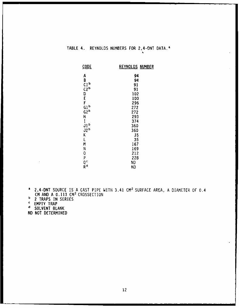
TABLE 4. REYNOLDS NUMBERS FOR 2,4-DNT DATA.a
CODE REYNOLDS NUMBER
A 94B 94Clb 91C2b 91D 102E 100F 296Gib 272G2b 272H 293I 374J 1 b 360J2 b 360K 35L 35M 167N 1690 212P 228QC ND
Rd ND
a 2,4-DNT SOURCE IS A CAST PIPE WITH 3.41 CM2 SURFACE AREA, A DIAMETER OF 0.4
CM AND A 0.113 CM2 CROSSECTIONb 2 TRAPS IN SERIESc EMPTY TRAPd SOLVENT BLANK
ND NOT DETERMINED
12
6.00e-9
5.00e-9 -
S4.00e-9
U- 3.00e-9 -
uJ
2.00e-9 -
0
0_ 1.00e-9
O.OOe+O0 100 200 300 400
REYNOLDS NUMBER
Figure 6. Plot of rate of evaporation of TNT at 23-25°C versus thecalculated Reynolds numbers for nitrogen flowing acrossthe surface.
13
1.00e-7 - a
C,.
. 8.00e-8 -
(6.00e-8t
0
LU
4.00e-8
0
LU-
2.00e-8 ,0 100 200 300 400
REYNOLDS NUMBER
Figure 7. Plot of rate of evaporation of 2,4-DNT at 23-25°C versusthe calculated Reynolds numbers for nitrogen flowingacross the surface.
14
CONCLUSION
For the first time, the rate of TNT and 2,4-DNT evaporation into air (gmin` cm"2) under ambient conditions has been measured. This measurementallows for the validation of the Griffy model for estimating TNT in air fordetection of explosives.
15
LITERATURE CITED
1. Pella, P. A. 1977. Measurement of the vapor pressures of TNT, 2,4-DNT,2,6-DNT, and EGDN. J. Chem. Thermodyn. 9(4), 301-305.
2. Dionne, B.C., D.P. Roounbehler, E.K. Achter, J.R. Hobbs and D.H. Fine.1986. Vapor pressure of explosives. J. Energetic Materials. 4:447-472.
3. Pella, P. A. 1976. Generator for producing trace vapor concentrations of2,4,6-trinitrotoluene, and ethylene glycol dinitrate for calibratingexplosives vapor detectors. Anal. Chem. 48(11):1632-1637.
4. Griffy, T. 1989. A model of explosive vapor concentration. Paperpresented at the 3rd International Symposium on Analysis and Detection ofExplosives, July 10-13, sponsored by the Army Research Development andStandardization Group (United Kingdom), at Mannheim, Germany.
5. Brueggemann, E.E. 1986. Liquid chromatographic determination ofexplosives and polynuclear aromatic hydrocarbons (PAHs) in deactivationfurnace ash. Technical Report 8604, AD A171269. U.S. Army BioengineeringResearch and Development Laboratory, Fort Detrick, Frederick, MD.
6. Griffy, T. 1992. A model of explosives vapor concentration II. Paperpresented at the 4th International Sumposium on Analysis and Detection ofExplosives, at Jerusalem.
16
DISTRIBUTION LIST
4 CommanderU.S. Army Medical Research and Development CommandATTN: SGRD-RMI-SFort DetrickFrederick, MD 21702-5012
2 CommanderU.S. Army Biomedical Research and Development LaboratoryATTN: SGRD-UBZ-ILFort DetrickFrederick, MD 21702-5010
2 Defense Technical Information Center (DTIC)ATTN: DTIC-FDACCameron StationAlexandria, VA 22304-6145
2 CommanderU.S. Army Medical Department Center and SchoolATTN: HSMC-FCFort Sam Houston, TX 78234-6100