54
1 Seakeeping Tests (with ships) Experimental Methods in Marine Hydrodynamics Lecture in week 43

1
Seakeeping Tests (with ships)
Experimental Methods in Marine Hydrodynamics
Lecture in week 43
2
Topics
• Why do seakeeping tests?
• What to do?– Activities
– Details of model test set-up and instrumentation
– Waves and wave calibration
• In-depth topics:– Test configurations
– Measurement of global forces
– Measurement of local (slamming) forces
– Speed loss due to waves
• Example project – testing the ADX Express pentamaran
• Labtest 4

3
Why do seakeeping tests?
Typical Objectives
• Reveal possible seakeeping problems with a new design
• Measure added resistance and speed loss due to waves
• Determine operational limits
• Optimization of design with respect to seakeeping
• Measure design loads
• Capsize and safety studies
• Development and testing of motion damping systems
• Studies of propulsion in waves

4
Activities (in typical sequence)
1. Manufacture of model (see pres. Week 38)
2. Do calm water performance tests (if ordered) (Week 34)
3. Instrumentation of model (Week 35)
• Calibrate transducers (Week 34)
• Mount all onboard instruments
4. Dynamic ballasting (Week 38)
• Place ballast loads to obtain correct centre of gravity and radius of gyration in pitch
5. Calibration of waves (without model in the lab) (Week 38)
6. Performance of tests
7. Data analysis and reporting (Week 36)

5
Two test modes:
• Free model
– Measurement of motions and accelerations
– Possibly measurement of internal global or local (slamming)
forces
– This is the most commonly used method – a direct modeling
of the real ship behavior
• Fixed model
– Measurement of total forces on the model
– Model might be given forced motions (radiation forces) or
being fixed in incoming waves (excitation forces)
– Used to verify and validate numerical methods

6
”Free” model – different test set-ups
1. Model free to heave, pitch (and surge)
2. Model with restricted horizontal motions
3. Model completely free

7
1. Model free to heave, pitch (and surge)
- unpowered model
• Head and following seas
• With forward speed
• In a towing tank
• Measurements (typical):
– Heave and pitch motions
– Vertical accelerations
– Added resistance due to waves
– Relative wave motions

8
1. Model free to heave, pitch (and surge)
- powered model
• Head and following seas
• With forward speed
• In a towing tank
• Measurements:
– Heave and pitch motions
– Vertical accelerations
– Propeller thrust, torque and RPM
– Speed loss and/or added power
– Relative wave motions

9

10
2. Model with restricted horizontal motions- Suspended in a system of thin wires and springs
• All headings
• With or without forward speed
• In a towing tank or seakeeping basin
• Measurements:
– 6 DoF motions (by optical position measurement system)
– Vertical accelerations
– Drift forces
– Relative wave motions

11
Ship model
Spring
90 deg
To land
To land
To land
To land
Spring
90 deg
Spring
Spring
Setup typical for ocean
basin tests at zero
forward speed
Note: Natural frequencies of the mass-spring
system must be far lower than the wave
excitation frequencies
What happens if the natural frequency is much
higher than the wave excitation frequencies?

12

13
Model
Pre-tensioned wiresBeam(fixed to model)
Force transducersMeasuring force in axial direction
Set-up for test in towing tank at forward speed
X-force transducer
14
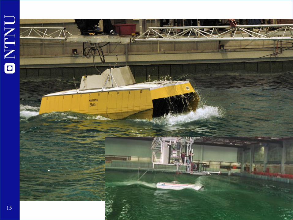
3. Model completely free
• Must be self-propelled
• Must have active rudder/steering
• Should have auto-pilot
• Might have a bundle of cables to a carriage, or be completely free, with battery power
• Measurements:
– 6 DoF motions (by optical position measurement system)
– Accelerations (vertical, lateral and longitudinal)
– Yaw rate (for auto-pilot) by rate gyro
– Global forces in the hull beam
– Local (slamming) forces
– Relative wave motions
15

17
Waves – an important part of a seakeeping test!
• Irregular wave spectra- Direct measurement of
seakeeping in a realistic sea state
- Requires long measurement time
series
• Regular waves- ”Measurement” of Response
Amplitude Operators (RAO), for
comparison and tuning of
calculations
- Design-wave approach
- Accelerated tests of dynamic
stability
• Transient wave (Impulse wave)
Can give RAO for many frequencies
simultaneously
• “Pink noise”“White noise” with limited band-width

18
Transient waves
• A sequence of waves of increasing length is
produced by the wave maker
• The longer waves travel faster than the shorter
waves
• The wave train is tuned in order to have all generated
waves reach one point at the same time
Result:
One single wave containing many frequencies

19
Transient wave at various locations

20
Time series Power spectraIn
pu
t w
ave
Ve
rt.a
cc. F
P
Transient wave tests with 160 m cruise liner

21
RAO derived from transient wave tests

22
“Pink noise”
Frequency
Wave spectral density
Aim is to excite as much of the frequency range as possible in order
to find RAOs
Difficult to generate large frequency range with almost equal wave
power spectral density
Wave-breaking limits energy in the high frequency range
Wavemaker amplitude limits energy in low frequency range

23
Wave calibration
t
h
S
Inverse FFT
Wave maker system
t
h
S
Wanted wave spectrum
Time realisation
Measured Time Series
FFT
Measuredwave spectrum
Comparison of wanted and measured wave spectrum.Adjustment of input wave parameters
Example of
comparison of
wanted and
measured wave
spectrum
24
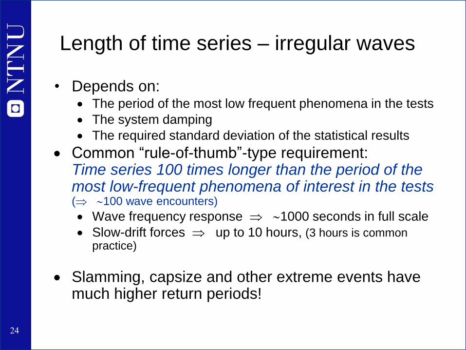
Length of time series – irregular waves
• Depends on: The period of the most low frequent phenomena in the tests
The system damping
The required standard deviation of the statistical results
Common “rule-of-thumb”-type requirement:Time series 100 times longer than the period of the most low-frequent phenomena of interest in the tests( 100 wave encounters)
Wave frequency response 1000 seconds in full scale
Slow-drift forces up to 10 hours, (3 hours is common practice)
Slamming, capsize and other extreme events have much higher return periods!

25
Length of time series – general and in
regular waves
• We are usually interested in stationary condition
transient response from start of test shall not influence
how long it takes from start to stationary conditions
depend mainly on the damping:
– Roll: low damping (transient 5-10 times roll natural period)
– Heave: high damping (transient < heave natural period)
– Speed (for self-propelled models): Depend on the propulsion
characteristics, but is of significant duration
• Regular waves: Need typically 10 wave cycles after
reaching stationary conditions (depending on how equal
the cycles are)

26
Testing of extreme and rarely
occurring events
• Ultimate strength (maximum loads) are often
assessed using a design wave
• Dynamic stability and capsize is often tested in large
regular waves
• Slamming is tested in selected irregular sea states

27
Design waves
• Non-linear numerical calculations and also model
experiments might take a long time to perform
• Instead of calculating or testing for a long time in a
realistic, extreme irregular seastate, one might create
a wave that is designed to be the worst possible in
the given sea state
• Linear seakeeping theory is used to find the worst
combination of the different frequency components in
the irregular spectrum
“According to Airy wave theory, the most unfavorable wave condition for a vessel is
not the wave of which all components have a peak at the same time instant, but the
wave leading to a response for which this is the case.” (Drummen et. al. 2008)

28
Design waves – cont.
• Most Likely Response Wave (MLRW)
– A wave designed to create a certain response
– Linear theory is used to establish the link between waves
and response
– An advanced numerical method or model tests is used to
find the actual response to this wave
• Conditional Random Response Wave (CRRW)
– Like the MLRW, but superimposed on an irregular
“background” wave
The fundamental assumption of wave conditioning techniques is that the nonlinear
response is a correction of the linear response. (Drummen et. al. 2008)
http://www.ivt.ntnu.no/imt/courses/tmr7/resources/Drummen_2008.pdf

29
Dynamic stability in waves
• Problems related to:
– Broaching
– Bow dive
– Coupled pitch-roll-yaw
• Problems usually occur
when groups of large regular
waves are encountered
• Rarely occurring event!
• Model testing in equivalent
regular waves of different
height and frequency

30
Dynamic stability in waves
Capacity
wave
maker
Steepness 1/10
Steepness 1/15
Steepness 1/20
0
2
4
6
8
10
12
14
16
18
5 6 7 8 9 10 11
Wave Period T (s)
Wa
ve
He
igh
t H
(m
)
/L=1.0 /L=1.25 /L=1.5 /L=2.0

31
Measurement of global loads
• Purpose:
To determine the design loads, used for
dimensioning of the ship structure
• Modeling alternatives:
– Backbone model
– Fully elastic model
– Segmented model
Strain gauges

32
Backbone model – during calibration

33
Backbone model – during testing
34
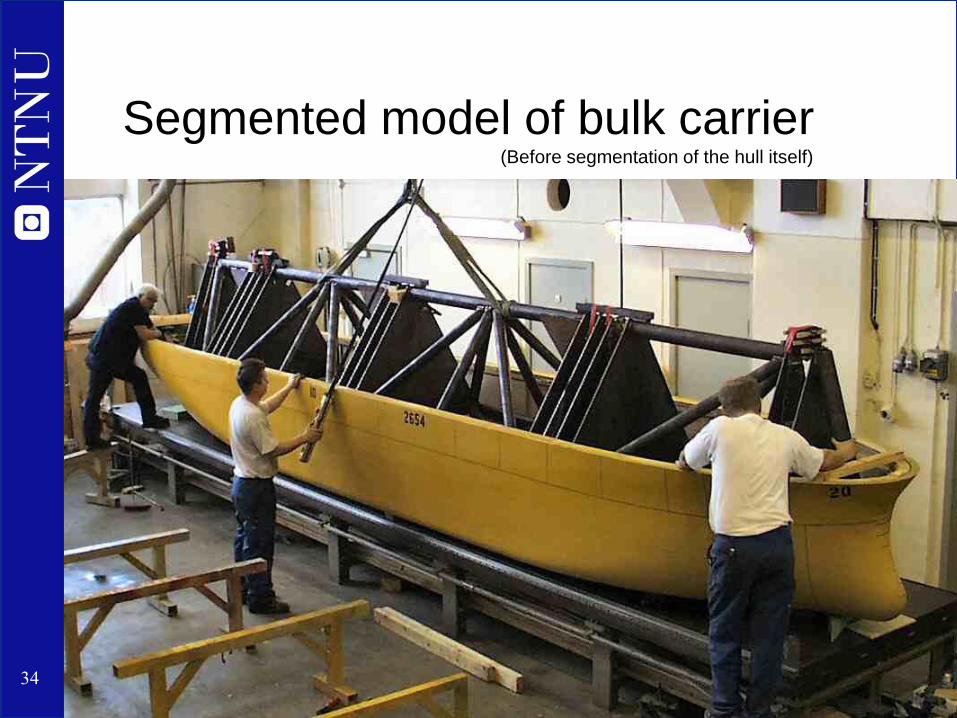
Segmented model of bulk carrier(Before segmentation of the hull itself)

35
Segmented models – frame and force
measurement
Hinge
Feather rod 3-comp. force transducers
Movable fasteningblock
Aluminium frame

37
6-component force transducers
3
1i
ixX
3
1i
iyY
3
1i
izZ
Sum of forces:y1
z1
y3
z3
y2
z2
Y
Z
= 3-comp. force transducers
MY
MZ
x2,3
z2,3
x1
z1
Z
MX
X
az1
ay
11232xM zz ayayy
11232yM zz axaxx
yayy 23zM

38
Location of segmentation cuts
• Depends on what you want to measure
– Midship bending moment midship
– Shear force due to slamming stern quarter
• For flexible models, it also depends on the number of
flexible modes

42
Model Tests of the ADX Express
•CFD calculations
•Initial resistance testing, 4 smaller models
•Resistance test, new model
•Optimisation for the longitudinal position of
the aft pair of sponsons
•Seakeeping tests with original and modified
design

43
44
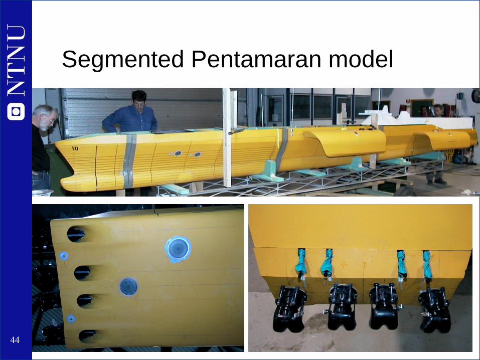
Segmented Pentamaran model

45
Segmented Pentamaran model - sponson

46
Objectives With Seakeeping Model
Testing
• Evaluate the wave-induced motions and accelerations.
• Measure occurrences of air entering the waterjet inlets.
• Measure occurrences of slamming.
• Establish the speed loss in irregular sea states.
• Evaluate the wave induced forces on the central hull and on the bridging
structures between the central hull and sponsons.
• Establish the response amplitude operators (RAO) in regular waves for certain
parameters to verify different hydrodynamic calculations and computer code.

47
Model Configuration
• 41 knots testing speed.
• Self-propelled model with four waterjets and nozzles controlled by an online Autopilot.
• Interceptor plates installed onto the aft pair of sponsons controlled in the online mode by
a PD-regulator by roll angle and rate of roll.
• Segmentation of the central hull into four sections with 5-component force transducers
connecting the sections.
• Installation of 5-component force transducers on each bridging structure between the
central hull and the sponsons.
• Maintaining the correct hydrostatic properties.
• Maintaining the correct LCG and mass moment of inertia around the transverse axis for
each model section.

48
Measurement of slamming
• Slamming is important for:
– Local loads dimensioning of plating and stiffeners
– Global whipping loads dimensioning of hull beam
– Noise and vibrations (comfort problem)
• Problem areas:
– Overhung sterns (flat with low draught)
– Bow flare
– Flat bottom (small ships in extreme seas)

49
Characteristics of slamming loads
• High peak pressure values
• Very short duration
• Elasticity of the structure is important

50
What is Hydroelasticity?
(Hutchison, 2011)

51
Fluid forces Structural response
Dynamic hydroelasticity
The deformation of the structure due to fluid loading has
significant impact on the fluid loading
Examples:
• Wing flutter
• Many types of slamming loads
• Vortex-induced vibrations
• Sea loads on many types of floating fish-farms

52
Requirements for measurement
• Extremely high sampling frequency (1 kHz)
• Fast rise time (quick response) of transducers
• Resonance frequency of transducer (including
fixture):
– Very low (by adding a big mass)
or
– Very high (by making an extremely stiff structure)
or
– Correctly modeled dynamic response
53
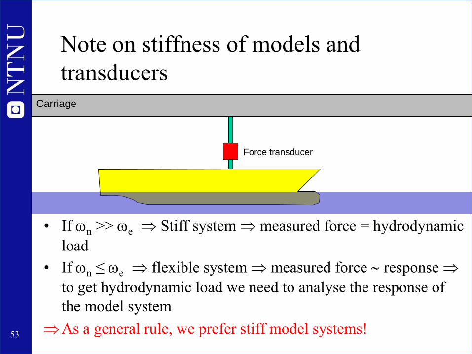
Note on stiffness of models and
transducers
• If n >> e Stiff system measured force = hydrodynamic
load
• If n ≤ e flexible system measured force response
to get hydrodynamic load we need to analyse the response of
the model system
As a general rule, we prefer stiff model systems!
Carriage
Force transducer

55
Different transducer configurations
• Point pressure measurements
– Needs very many pressure transducers
• Slamming panels
– Area similar to typical plating field
– Measure the integrated force on a representative area
• Segmented model
– Measuring force on entire afterbody or bow section
– Useful if interested in global effects, like whipping
• Different transducer configurations are often used in
combination

56
Different slamming transducer configs
Slamming panels in bow flare
Segmented stern for measure-
ment of integrated force
Slamming panels in overhung
Flat stern

57
Running of self-propelled models
- Alternatives
• Constant carriage speed
– controlling propeller revs manually to maintain same average
speed as carriage (can be a challenging task!)
• Constant propeller revs
– Easy to do with ordinary frequency-controlled AC motors or
brushless DC servo motors
• Constant propulsion power
– Can be easily done by using the built-in control system of the
drives of brushless DC servo motors, which are increasingly
used
Ca
rriag
e s
pe
ed
mu
st b
e a
dju
ste
d to
ma
tch
ave
rag
e m
od
el s
pe
ed

58
Calculation of total speed loss
PB
VS
Required powerin calm water
Required powerin waves
Prop.powerat constant RPM
Total speedloss
Meas. speedloss
Speed loss due to added power

60
Tank wall effects
Radiated waves=created by model motions
Diffracted waves=incoming waves reflected
by the model
2g
e
gc
Wave group speed:
21 1
2
M gM M
w
L cL LgUcrit
t B B
This is why you should not run zero speed tests in a towing tank!

65
Summary
• Purposes of seakeeping tests
• The three different test set-ups:
– Fixed, free, partly restrained
• Types of waves
– In depth: Impulse waves
• Recording time – length of tests
• How to handle rarely occurring events?
– Example: Testing dynamic stability
• Model Tests of the ADX Express
• Slamming and global forces
• Measuring speed loss and added power
• Tank wall interference


