ORIGINAL ARTICLE Experimental performance study of a proposed desiccant based air conditioning system M.M. Bassuoni * Mechanical Power Engineering Department, Faculty of Engineering, Tanta University, Egypt ARTICLE INFO Article history: Received 21 October 2012 Received in revised form 3 December 2012 Accepted 9 December 2012 Available online 11 January 2013 Keywords: Hybrid system Dehumidification Vapor compression system Liquid-desiccant ABSTRACT An experimental investigation on the performance of a proposed hybrid desiccant based air con- ditioning system referred as HDBAC is introduced in this paper. HDBAC is mainly consisted of a liquid desiccant dehumidification unit integrated with a vapor compression system (VCS). The VCS unit has a cooling capacity of 5.27 kW and uses 134a as refrigerant. Calcium chloride (CaCl 2 ) solution is used as the working desiccant material. HDBAC system is used to serve low sensible heat factor applications. The effect of different parameters such as, process air flow rate, desiccant solution flow rate, evaporator box and condenser box solution temperatures, strong solution concentration and regeneration temperature on the performance of the system is studied. The performance of the system is evaluated using some parameters such as: the coef- ficient of performance (COP a ), specific moisture removal and energy saving percentage. A remarkable increase of about 54% in the coefficient of performance of the proposed system over VCS with reheat is achieved. A maximum overall energy saving of about 46% is observed which emphasizes the use of the proposed system as an energy efficient air conditioning system. ª 2014 Cairo University. Production and hosting by Elsevier B.V. All rights reserved. Introduction Increasing of occupant comfort demands are leading to rising requirement for air conditioning, but deteriorating global en- ergy and environment crisis are starving for energy saving and environmental protection. The need to come up with the new energy saving as well as environmentally friend air condi- tioning systems has been more urgent than ever before. The li- quid desiccant dehumidification systems integrated with VCS driven by low-grade heat sources can satisfactorily meet those needs; meanwhile, they provide an ideal area for the applica- tion of waste heat discharged from local factories, and the employment of brine solutions as absorbent brings less damage to environment. The earliest liquid desiccant system was sug- gested and experimentally tested by Lof [1] using triethylene glycol as the desiccant. Many researchers [2–5] have all de- scribed different air handling systems using liquid desiccants. Adnan et al. [6] introduced an energy efficient system using liquid desiccant which is proposed to overcome the latent part of the cooling load in an air conditioning system. It can be concluded that the proposed system can be used effectively to reduce electric energy consumption in air conditioning to about 0.3 of the energy consumed by a conventional air condi- tioning system. Mohan et al. [7] studied the performance of absorption and regeneration columns for a liquid desiccant-va- por compression hybrid system. They reported that higher the specific humidity and lower the temperature of the inlet air, higher will be the dehumidification in the absorber. Similarly, * Tel.: +20-1005852335. E-mail address: [email protected]. Peer review under responsibility of Cairo University. Journal of Advanced Research (2014) 5, 87–95 Cairo University Journal of Advanced Research 2090-1232 ª 2014 Cairo University. Production and hosting by Elsevier B.V. All rights reserved. http://dx.doi.org/10.1016/j.jare.2012.12.002
strong solution concentration and regeneration temperature on the performance of the system
is studied. The performance of the system is evaluated using some parameters such as: the coef-
ficient of performance (COPa), specific moisture removal and energy saving percentage. A
remarkable increase of about 54% in the coefficient of performance of the proposed system over
VCS with reheat is achieved. A maximum overall energy saving of about 46% is observed which
emphasizes the use of the proposed system as an energy efficient air conditioning system.
ª 2014 Cairo University. Production and hosting by Elsevier B.V. All rights reserved.
Introduction
Increasing of occupant comfort demands are leading to risingrequirement for air conditioning, but deteriorating global en-ergy and environment crisis are starving for energy saving
and environmental protection. The need to come up with thenew energy saving as well as environmentally friend air condi-tioning systems has been more urgent than ever before. The li-
quid desiccant dehumidification systems integrated with VCSdriven by low-grade heat sources can satisfactorily meet those
needs; meanwhile, they provide an ideal area for the applica-
tion of waste heat discharged from local factories, and theemployment of brine solutions as absorbent brings less damageto environment. The earliest liquid desiccant system was sug-
gested and experimentally tested by Lof [1] using triethyleneglycol as the desiccant. Many researchers [2–5] have all de-scribed different air handling systems using liquid desiccants.
Adnan et al. [6] introduced an energy efficient system using
liquid desiccant which is proposed to overcome the latent partof the cooling load in an air conditioning system. It can beconcluded that the proposed system can be used effectively
to reduce electric energy consumption in air conditioning toabout 0.3 of the energy consumed by a conventional air condi-tioning system. Mohan et al. [7] studied the performance of
absorption and regeneration columns for a liquid desiccant-va-por compression hybrid system. They reported that higher thespecific humidity and lower the temperature of the inlet air,
higher will be the dehumidification in the absorber. Similarly,
h enthalpy, kJ/kg_m mass flow rate, kg/s_Q heat transfer rate, kWT temperature, �CV volume flow rate, l/minX desiccant solution concentration, kgd/kgsy air humidity ratio, kgv/kgda
Subscriptsa airda dry air
Reg regeneration
s desiccant solutionvap vapor
AbbreviationsAH auxiliary heater
COP coefficient of performanceCaCl2 calcium chlorideHDBAC hybrid desiccant based air conditioning system
SMR specific moisture removal, kgv/kgsVCS vapor compression system
88 M.M. Bassuoni
the regeneration can be increased by increasing the tempera-
ture and decreasing the specific humidity of the inlet air tothe regenerator. Jia et al. [8] introduced a hybrid desiccant-as-sisted air conditioner and split cooling coil system, which com-
bines the merits of moisture removal by desiccant and coolingcoil for sensible heat removal, which is a potential alternativeto conventional vapor compression cooling systems. It is foundthat, compared with the conventional VCS; the hybrid desic-
cant cooling system economizes 37.5% electric energyconsumption.
Ge et al. [9] introduced a solar driven two-stage rotary des-
iccant cooling system and a vapor compression system are sim-ulated to provide cooling for one floor in a commercial officebuilding in two cities with different climates: Berlin and Shang-
hai. Results illustrated that the required regeneration tempera-tures are 55 �C in Berlin and 85 �C in Shanghai. As comparedto the vapor compression system, the desiccant cooling system
has better supply air quality and consumes less electricity. Jon-gsoo et al. [10] provided a detailed evaluation of the perfor-mance of a four-partition desiccant wheel to make a low-temperature driving heat source possible and achieve consider-
able energy saving by the simulation and experiment. Theymentioned that hybrid air-conditioning system improvesCOP by approximately 94% as compared to the conventional
vapor compression-type refrigerator. Niu et al. [11] introduceda performance analysis of liquid desiccant based air-condition-ing system under variable fresh air ratios. They reported that,
compared to a conventional air-conditioning system with pri-mary return air, the liquid desiccant based system consumesnotably less power. The maximum power saving ratio is58.9%when the fresh air ratio is 20%, and the minimum is
4.6%when the fresh air ratio is 100%. Researches on hybridcooling system are also reported [12–16]. Jiazhen et al. [17]introduced and tested a desiccant wheel (DW)-assisted sepa-
rate sensible and latent cooling (SSLC) air-conditioning sys-tems by using CO2 and R-410a as refrigerant. They foundthat at a regeneration temperature of 50 �C, the coefficient of
performance (COP) of the vapor compression cycles improvedby 7% from the respective baseline systems for both refriger-ants. A two desiccant-coated heat exchangers (DCHEs), which
are actually fin-tube heat exchanging devices coated with silicagel and polymer materials respectively, are investigated exper-imentally by Ge et al. [18]. An experimental setup was designedand built to test the performance of this unit. They found that
this desiccant-coated fin-tube heat exchanger well overcomes
the side effect of adsorption heat which occurs in desiccantdehumidification process, and achieves good dehumidificationperformance under given conditions. The silica gel coated heat
exchanger behaves better than the polymer one. The influencesof regeneration temperature, inlet air temperature and humid-ity on the system performance in terms of average moisture re-moval rate and thermal coefficient of performance were also
analyzed. The performance of DCHE system, using conven-tional silica gel as desiccant material and a novel solar drivendesiccant coated heat exchanger cooling (SDCC) system is also
proposed by Ge et al. [19,20].In this paper, experimental tests are carried out to investi-
gate the performance of the proposed HDBAC system. The ef-
fects of the relevant operating parameters on the performanceof the whole system are studied and analyzed. The HDBACsystem is designed to meet the needs of cooling, dehumidifica-
tion and reducing energy consumption in hot humid areas;places with high latent load portions; such as supermarkets,theaters or auditoriums.
Experimental
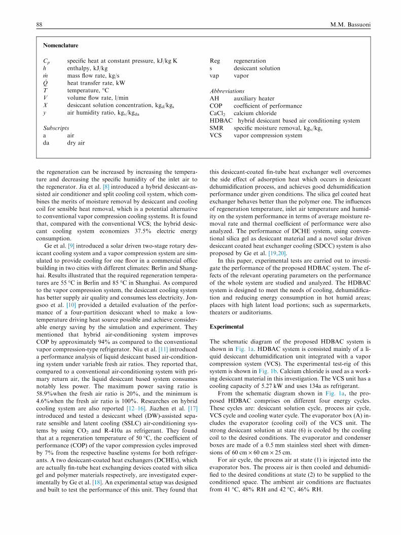
The schematic diagram of the proposed HDBAC system isshown in Fig. 1a. HDBAC system is consisted mainly of a li-
quid desiccant dehumidification unit integrated with a vaporcompression system (VCS). The experimental test-rig of thissystem is shown in Fig. 1b. Calcium chloride is used as a work-
ing desiccant material in this investigation. The VCS unit has acooling capacity of 5.27 kW and uses 134a as refrigerant.
From the schematic diagram shown in Fig. 1a, the pro-
posed HDBAC comprises on different four energy cycles.These cycles are: desiccant solution cycle, process air cycle,VCS cycle and cooling water cycle. The evaporator box (A) in-
cludes the evaporator (cooling coil) of the VCS unit. Thestrong desiccant solution at state (6) is cooled by the coolingcoil to the desired conditions. The evaporator and condenserboxes are made of a 0.5 mm stainless steel sheet with dimen-
sions of 60 cm · 60 cm · 25 cm.For air cycle, the process air at state (1) is injected into the
evaporator box. The process air is then cooled and dehumidi-
fied to the desired conditions at state (2) to be supplied to theconditioned space. The ambient air conditions are fluctuatesfrom 41 �C, 48% RH and 42 �C, 46% RH.
Fig. 1c Psychometric process of the proposed HDBAC system.
Fig. 1a Schematic diagram of HDBAC system.
Fig. 1b The experimental test-rig of HDBAC system.
Desiccant based air conditioning system 89
For desiccant solution cycle, the strong desiccant solutionat state (6) is directly sprayed on the VCS evaporator inside
the evaporator box. While the dilute desiccant solution at state(3) is pumped to the condenser box (B) which contains the con-denser of the VCS unit. The dilute desiccant solution is pre-
heated to state (4) by the condenser heat. The preheating pro-cess is intended to save some of the energy required for desic-cant solution regeneration process. An auxiliary heater (C) is
used to completely regenerate the desiccant solution to the re-quired operation concentration.
For cooling water cycle, an evaporative type heat exchanger(D) with an effectiveness of 0.85 is used for pre-cooling thestrong desiccant solution from state (5) to state (6) before it
has been delivered to the evaporator box. The cooling waterrequired for this process is received from a cooling water tank(E) at state (7). The cooling water temperature is kept nearlyconstant during experiment at 24 �C.
Some components of the experimental test rig are perfectlyinsulated. These components are such as, the evaporator box,condenser box and auxiliary heater. The process air and desic-
cant solution flow rates are controlled by using control valves.The psychometric chart of the process air of the proposed
system is shown in Fig. 1c. The solid line; process 1–2; denotes
the HDBAC system process. The dashed line 1–2a–2 repre-sents the comparable conventional system (process 1–2a iscooling with dehumidification over the direct expansion evap-orator of the VCS unit and process 2a–2 is reheating to the de-
sired conditions of the supply air). This conventional system iscalled VCS with reheat.
8 12 16 20
Evaporator Box Temperature ( C)
2
2.5
3
3.5
4
CO
P a
Vs = 5 L/minVs = 4 L/minVs = 3 L/min
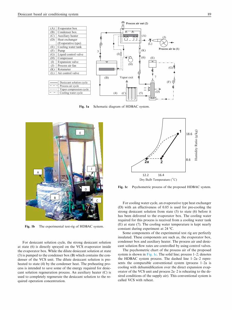
Fig. 2a Effect of evaporator box temp. on COPa.
90 M.M. Bassuoni
Measurements and instrumentation
Suitable measuring devices for data recording of the experi-mental runs are used. Air and solution temperatures are mea-
sured using type K thermocouples and a digital temperaturereader with accuracy of 0.11 �C. Solution flow rates are mea-sured using glass rotameters with 2% full scale accuracy.
The density of the desiccant solution is measured using anaccurate digital scale with accuracy of 0.01 g. These densitiesat its known temperatures are used to determine the concentra-tions of the desiccant solution from CaCl2 properties table. Air
velocity and humidity are measured using a multi-function hotwire measuring device with accuracy of 0.015 m/s for the veloc-ity and of 3% for the relative humidity. The power consump-
tion is measured using a watt meter with accuracy of0.035 kW. The uncertainty of air and solution mass flow rateis 5.8% and 4.5%; respectively. The uncertainty of air enthal-
py, heat transfer rate and COP is 2.7%, 6.1% and 8.2%;respectively. The uncertainty of specific moisture recovery is8.5%.
Experimental tests are carried out to evaluate the perfor-mance of the proposed HDBAC system at different conditions.The following variables are required to be measured, tempera-ture and humidity of the process air at the inlet and exit of the
evaporator box, solution regeneration temperature, solutionconcentrations and temperatures, air velocity for process airand solution flow rates.
Performance analysis
In the present work, some important parameters are used for
evaluating the performance of the proposed HDBAC systemas follows.
Coefficient of performance (COP)
The proposed system coefficient of performance COPa is calcu-lated from:
COPa ¼_maðh1 � h2Þ_WC þ _QAH
ð1Þ
where _ma is the mass flow rate of air, h is the enthalpy of air,_WC is the compressor power consumption and _QAH is the aux-
iliary regeneration heat rate which may be calculated from:
_QAH ¼ _mSðhS5 � hS4Þ ð2Þ
where _mS is the mass flow rate of desiccant solution and the en-
thalpy of CaCl2 solution may be obtained from [21] as follows:
hS ¼ CPSTS ð3Þ
where Cps is the specific heat of CaCl2–H2O solution atconstant pressure in (J/kg �C) and it can be calculated in
terms of its concentration Xs (kgd/kgs) and temperature Ts
(�C) from:
CPS ¼ 4027þ 1:859Ts � 5354Xs þ 3240X2s ð4Þ
The VCS with reheat coefficient of performance COPb is calcu-
lated as follows:
COPb ¼_maðh1 � h2aÞ_WC þ _QRe heat
ð5Þ
_QRe heat ¼ _maðh2 � h2aÞ ð6Þ
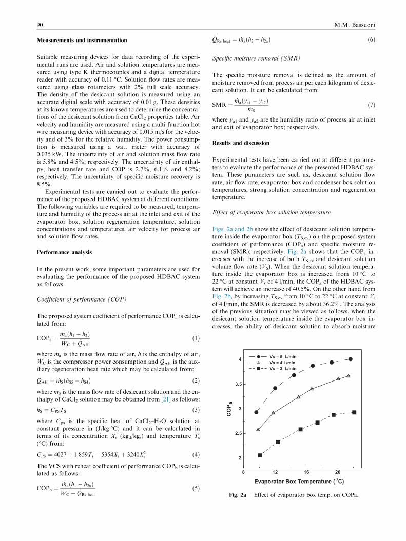
Specific moisture removal (SMR)
The specific moisture removal is defined as the amount ofmoisture removed from process air per each kilogram of desic-
cant solution. It can be calculated from:
SMR ¼ _maðya1 � ya2Þ_mS
ð7Þ
where ya1 and ya2 are the humidity ratio of process air at inletand exit of evaporator box; respectively.
Results and discussion
Experimental tests have been carried out at different parame-
ters to evaluate the performance of the presented HDBAC sys-tem. These parameters are such as, desiccant solution flowrate, air flow rate, evaporator box and condenser box solution
temperatures, strong solution concentration and regenerationtemperature.
Effect of evaporator box solution temperature
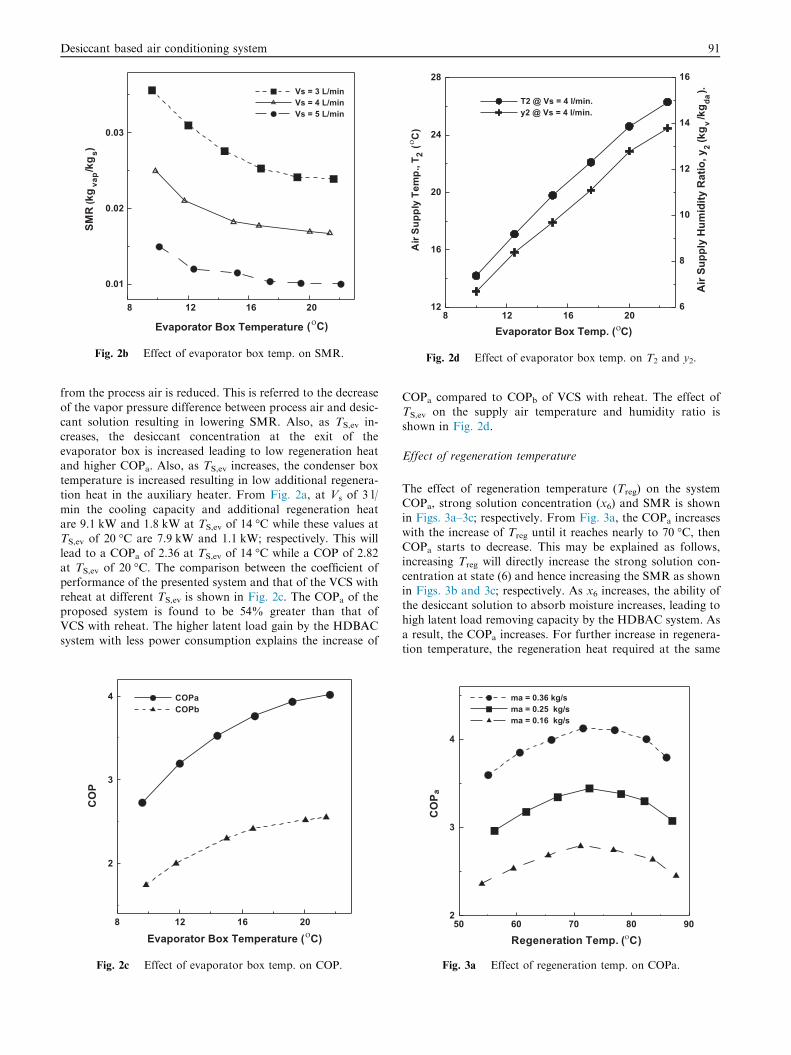
Figs. 2a and 2b show the effect of desiccant solution tempera-ture inside the evaporator box (TS,ev) on the proposed systemcoefficient of performance (COPa) and specific moisture re-
moval (SMR); respectively. Fig. 2a shows that the COPa in-creases with the increase of both TS,ev and desiccant solutionvolume flow rate (VS). When the desiccant solution tempera-
ture inside the evaporator box is increased from 10 �C to22 �C at constant Vs of 4 l/min, the COPa of the HDBAC sys-tem will achieve an increase of 40.5%. On the other hand from
Fig. 2b, by increasing TS,ev from 10 �C to 22 �C at constant Vs
of 4 l/min, the SMR is decreased by about 36.2%. The analysisof the previous situation may be viewed as follows, when the
desiccant solution temperature inside the evaporator box in-creases; the ability of desiccant solution to absorb moisture
8 12 16 20
0.01
0.02
0.03
SMR
(kg
vap/
kgs)
Vs = 3 L/minVs = 4 L/minVs = 5 L/min
Evaporator Box Temperature ( C)
Fig. 2b Effect of evaporator box temp. on SMR.
8 12 16 20Evaporator Box Temp. ( C)
12
16
20
24
28
6
8
10
12
14
16
Air
Supp
ly H
umid
ity R
atio
, y2
(kg v
/kg da
).
T2 @ Vs = 4 l/min.y2 @ Vs = 4 l/min.
Fig. 2d Effect of evaporator box temp. on T2 and y2.
Desiccant based air conditioning system 91
from the process air is reduced. This is referred to the decrease
of the vapor pressure difference between process air and desic-cant solution resulting in lowering SMR. Also, as TS,ev in-creases, the desiccant concentration at the exit of the
evaporator box is increased leading to low regeneration heatand higher COPa. Also, as TS,ev increases, the condenser boxtemperature is increased resulting in low additional regenera-tion heat in the auxiliary heater. From Fig. 2a, at Vs of 3 l/
min the cooling capacity and additional regeneration heatare 9.1 kW and 1.8 kW at TS,ev of 14 �C while these values atTS,ev of 20 �C are 7.9 kW and 1.1 kW; respectively. This will
lead to a COPa of 2.36 at TS,ev of 14 �C while a COP of 2.82at TS,ev of 20 �C. The comparison between the coefficient ofperformance of the presented system and that of the VCS with
reheat at different TS,ev is shown in Fig. 2c. The COPa of theproposed system is found to be 54% greater than that ofVCS with reheat. The higher latent load gain by the HDBAC
system with less power consumption explains the increase of
8 12 16 20
2
3
4
CO
P
COPaCOPb
Evaporator Box Temperature ( C)
Fig. 2c Effect of evaporator box temp. on COP.
COPa compared to COPb of VCS with reheat. The effect ofTS,ev on the supply air temperature and humidity ratio is
shown in Fig. 2d.
Effect of regeneration temperature
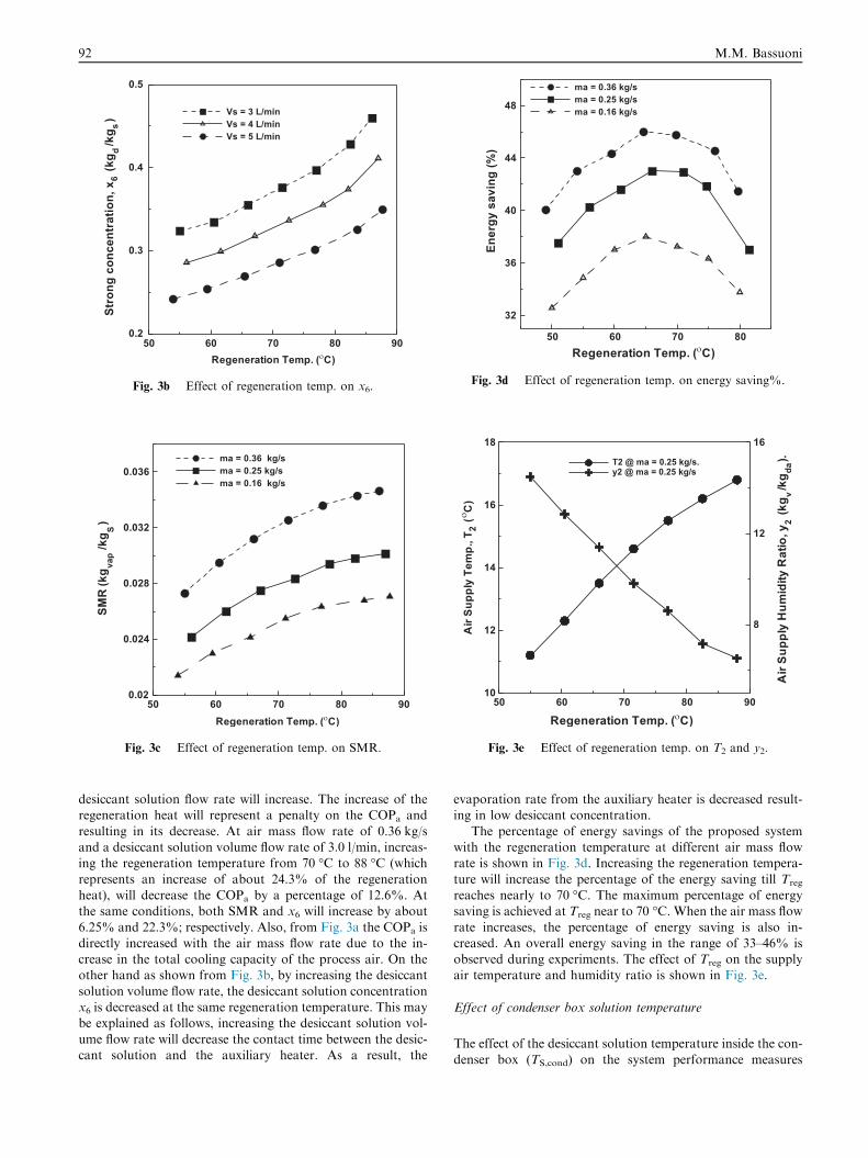
The effect of regeneration temperature (Treg) on the systemCOPa, strong solution concentration (x6) and SMR is shownin Figs. 3a–3c; respectively. From Fig. 3a, the COPa increases
with the increase of Treg until it reaches nearly to 70 �C, thenCOPa starts to decrease. This may be explained as follows,increasing Treg will directly increase the strong solution con-
centration at state (6) and hence increasing the SMR as shownin Figs. 3b and 3c; respectively. As x6 increases, the ability ofthe desiccant solution to absorb moisture increases, leading tohigh latent load removing capacity by the HDBAC system. As
a result, the COPa increases. For further increase in regenera-tion temperature, the regeneration heat required at the same
50 60 70 80 902
3
4
CO
P a
ma = 0.36 kg/s ma = 0.25 kg/sma = 0.16 kg/s
Fig. 3a Effect of regeneration temp. on COPa.
50 60 70 80 900.2
0.3
0.4
0.5
Stro
ngco
ncen
trat
ion,
x 6(k
g d/k
g s) Vs = 3 L/min
Vs = 4 L/minVs = 5 L/min
Fig. 3b Effect of regeneration temp. on x6.
50 60 70 80 900.02
0.024
0.028
0.032
0.036
SMR
(kg va
p/k
g S)
ma = 0.36 kg/sma = 0.25 kg/sma = 0.16 kg/s
Fig. 3c Effect of regeneration temp. on SMR.
50 60 70 80
32
36
40
44
48
Ener
gysa
ving
(%)
ma = 0.36 kg/sma = 0.25 kg/sma = 0.16 kg/s
Fig. 3d Effect of regeneration temp. on energy saving%.
50 60 70 80 9010
12
14
16
18
8
12
16
Air
Supp
lyH
u mid
i tyR
atio
,y2
(kg v
/ kg da
).T2 @ ma = 0.25 kg/s.y2 @ ma = 0.25 kg/s
Fig. 3e Effect of regeneration temp. on T2 and y2.
92 M.M. Bassuoni
desiccant solution flow rate will increase. The increase of theregeneration heat will represent a penalty on the COPa and
resulting in its decrease. At air mass flow rate of 0.36 kg/sand a desiccant solution volume flow rate of 3.0 l/min, increas-ing the regeneration temperature from 70 �C to 88 �C (which
represents an increase of about 24.3% of the regenerationheat), will decrease the COPa by a percentage of 12.6%. Atthe same conditions, both SMR and x6 will increase by about
6.25% and 22.3%; respectively. Also, from Fig. 3a the COPa isdirectly increased with the air mass flow rate due to the in-crease in the total cooling capacity of the process air. On theother hand as shown from Fig. 3b, by increasing the desiccant
solution volume flow rate, the desiccant solution concentrationx6 is decreased at the same regeneration temperature. This maybe explained as follows, increasing the desiccant solution vol-
ume flow rate will decrease the contact time between the desic-cant solution and the auxiliary heater. As a result, the
evaporation rate from the auxiliary heater is decreased result-ing in low desiccant concentration.
The percentage of energy savings of the proposed systemwith the regeneration temperature at different air mass flowrate is shown in Fig. 3d. Increasing the regeneration tempera-
ture will increase the percentage of the energy saving till Treg
reaches nearly to 70 �C. The maximum percentage of energysaving is achieved at Treg near to 70 �C. When the air mass flow
rate increases, the percentage of energy saving is also in-creased. An overall energy saving in the range of 33–46% isobserved during experiments. The effect of Treg on the supplyair temperature and humidity ratio is shown in Fig. 3e.
Effect of condenser box solution temperature
The effect of the desiccant solution temperature inside the con-
denser box (TS,cond) on the system performance measures
36 40 44 48 52
2
2.5
3
3.5C
OP a
Vs = 5 L/minVs = 4 L/minVs = 3 L/min
TS,cond ( C)
Fig. 4a Effect of condenser box temp. on COPa.
36 40 44 48 52
0.024
0.028
0.032
SMR
(kg va
p/k
g s)
ma = 0.36 kg/sma = 0.25 kg/sma = 0.16 kg/s
TS,cond ( C)
Fig. 4b Effect of condenser box temp. on SMR.
36 40 44 48 52 56TS,cond ( C)
12
14
16
18
20
Air
Supp
lyTe
mp.
, T2
(C
)
8
10
12
14
Air
Supp
lyH
umid
ityR
atio
,y2
(kg
v/k
g da).
T2 @ ma = 0.25 kg/s.y2 @ ma = 0.25 kg/s.
Fig. 4c Effect of condenser box temp. on T2 and y2.
0.32 0.36 0.4 0.44
Strong concentration, X6 (kgd /kgs)
2
2.4
2.8
3.2
3.6C
OP a
ma = 0.36 kg/sma = 0.25 kg/sma = 0.16 kg/s
Fig. 5a Effect of strong concentration, x6 on COPa.
Desiccant based air conditioning system 93
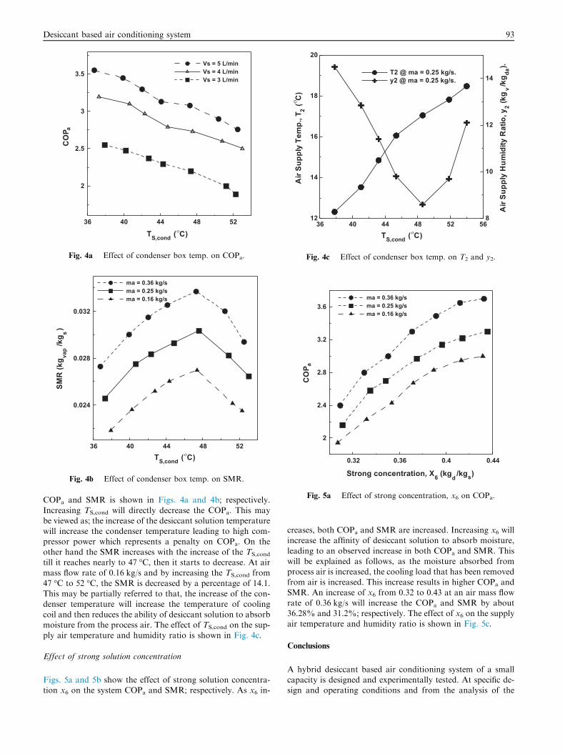
COPa and SMR is shown in Figs. 4a and 4b; respectively.
Increasing TS,cond will directly decrease the COPa. This maybe viewed as; the increase of the desiccant solution temperaturewill increase the condenser temperature leading to high com-pressor power which represents a penalty on COPa. On the
other hand the SMR increases with the increase of the TS,cond
till it reaches nearly to 47 �C, then it starts to decrease. At airmass flow rate of 0.16 kg/s and by increasing the TS,cond from
47 �C to 52 �C, the SMR is decreased by a percentage of 14.1.This may be partially referred to that, the increase of the con-denser temperature will increase the temperature of cooling
coil and then reduces the ability of desiccant solution to absorbmoisture from the process air. The effect of TS,cond on the sup-ply air temperature and humidity ratio is shown in Fig. 4c.
Effect of strong solution concentration
Figs. 5a and 5b show the effect of strong solution concentra-tion x6 on the system COPa and SMR; respectively. As x6 in-
creases, both COPa and SMR are increased. Increasing x6 willincrease the affinity of desiccant solution to absorb moisture,
leading to an observed increase in both COPa and SMR. Thiswill be explained as follows, as the moisture absorbed fromprocess air is increased, the cooling load that has been removed
from air is increased. This increase results in higher COPa andSMR. An increase of x6 from 0.32 to 0.43 at an air mass flowrate of 0.36 kg/s will increase the COPa and SMR by about
36.28% and 31.2%; respectively. The effect of x6 on the supplyair temperature and humidity ratio is shown in Fig. 5c.
Conclusions
A hybrid desiccant based air conditioning system of a smallcapacity is designed and experimentally tested. At specific de-sign and operating conditions and from the analysis of the
0.32 0.36 0.4 0.44
Strong concentration, x6 (kgd /kgs)
0.024
0.028
0.032
0.036SM
R(k
g vap
/kg s
)ma = 0.36 kg/sma = 0.25 kg/sma = 0.16 kg/s
Fig. 5b Effect of strong concentration, x6 on SMR.
Fig. 5c Effect of strong concentration, x6 on T2, y2.
94 M.M. Bassuoni
experimental results, some important conclusions can be sum-
marized as follows:
� The coefficient of performance of the proposed system is
found to be 54% greater than that of VCS with reheat attypical operating conditions.� The HDBAC system integrated with a 5.27 kW conven-tional VCS can replace a VCS with reheat with a cooling
capacity of 9.13 kW.� The coefficient of performance and the specific moistureremoval of the proposed system are both increased with
increasing both air and desiccant solution flow rates.� An increase of strong solution concentration will increaseboth COPa and SMR.
� The COPa increases and SMR decreases by increasing thetemperature of the desiccant solution inside the evaporator.
� The COPa is decreased and SMR is increased when the
regeneration temperature is increased.� The HDBAC system has been achieved a percentage of anenergy savings in the range of 33–46%.
Conflict of interest
The authors have declared no conflict of interest.
References
[1] Lof GOG. Cooling with solar energy. In: Congress on solar
energy, Tuuson, Arizona; 1955. p. 171–89.
[2] Li Z, Liu XH, Jiang Y, Chen XY. New type of fresh air
processor with liquid desiccant total heat recovery. Energy Build
2005;37:587–93.
[3] MahmoudmKG, Ball HD. Liquid desiccant systems simulation.
Int J Refrig 1992;15(2):74–80.
[4] Elasyed SS, Hamamoto Y, Akisawa A, Kashiwagi T. Analysis
of an air cycle refrigerator driving air conditioning system
integrated desiccant system. Int J Refrig 2006;29:219–28.
[5] Kessling W, Laevemann E, Peltzer M. Energy storage in open
cycle liquid desiccant cooling systems. Int J Refrig
1998;21(2):150–6.
[6] Adnan KK, Elsayed MM, Alraghi MO. Proposed energy
efficient air conditioning system using liquid desiccant. Appl
Therm Eng 1996;16:791–806.
[7] Mohan BS, Maiya, Shaligram T. Performance characterisation
of liquid desiccant columns for a hybrid air-conditioner. Appl
Therm Eng 2008;28:1342–55.
[8] Jia CX, Dai YJ, Wu JY, Wang RZ. Analysis on a hybrid
desiccant air-conditioning system. Appl Therm Eng
2006;26:2393–400.
[9] Ge TS, Ziegler F, Wang RZ, Wang H. Performance comparison
between a solar driven rotary desiccant cooling system and
conventional vapor compression system. Appl Therm Eng
2010;30:724–31.
[10] Jongsoo J, Yamaguchi S, Saito K, Kawai S. Performance
analysis of four-partition desiccant wheel and hybrid
dehumidification air-conditioning system. Int J Refrig
2010;33:496–509.
[11] Niu X, Xiao F, Ge G. Performance analysis of liquid desiccant
based air-conditioning system under variable fresh air ratios.
Energy Build 2010;42:2457–64.
[12] Studak JW, Peterson JL. A preliminary evaluation of alternative
liquid desiccants for a hybrid desiccant air conditioner. In:
Proceeding of the fifth annual symposium on improving building
energy efficiency in hot and humid climates, vol. 13, no. 14,
Houston; 1988. p. 155–9.
[13] Maclaine C IL. Proposal for a hybrid desiccant air conditioning
system. In: Proceedings of the symposium on desiccant cooling