Experimental Simulation of Multi-Static Radar with a Pair of Separated Movable Antennas
Andrey Zhuravlev, Vladimir Razevig, Sergey Ivashov, Alexander Bugaev, and Margarita Chizh
Remote Sensing Laboratory, Bauman Moscow State Technical University, Moscow, 105005, RussiaAbstract — This paper describes a setup for experimental
simulation of the signal obtained in electronically switched sparse antenna arrays by independently moving one transmit and one receive antennas. The concept of the system is given with detailed description of the current working realization and the methodology of conducting experiments. Examples of acquired radar signals are presented with corresponding radar images obtained after processing. Potential applications of the setup system in a variety of research projects are given. Further improvements of the system are suggested.
A major advantage of a multi-static radar system with a sparse antenna array is in substantial reduction of the number of applied antennas and the required microwave hardware behind the antenna array itself. It is the large number of antenna elements and the complexity of the antenna electronic switching sub-system that define the high price of a radar system that uses mono-static antenna arrays, where fixed transmitter-receiver pairs and dense sampling are traditionally used. The effective reduction of the number of antennas in a multi-static radar system is due to the fact that the same sampling volume is achieved by many available transmitter-receiver combinations that are arranged to form a dense, possibly non-redundant, distribution of effective samples [1], [2].
Design and development of a full scale multi-static radar system at the research stage, when a proof-of-concept results are expected, might be not optimal due to limits in budget, resources, or flexibility. The latter manifests itself by inability to test an optionally increased number of antenna elements with a changeable spatial configuration and the other types of antennas. In this paper, estimating the potential of a short-range multi-static radar system for certain applications is done by applying a pair of independently movable antennas capable of performing phase measurements of the radar signal on transmitter-object-receiver propagation paths inherent to all transmit-receive combinations of an electronically switched multi-static array. Among the advantages of such an approach are numerous possibilities to fine-tune the system before designing a fixed system with multiple antenna elements and a complex switch matrix behind them: the possibility to test various antenna types by creating only a pair of each type, experimentally proofing the proper spatial static antenna configuration to achieve the best ratio between the complexity of the system and the quality of generated radar images; the estimation of
the antenna directivity, bandwidth, quantity and spacing impact on the performance of the ultimate radar system.
This paper covers a possible approach to creating such a measurement system. The implemented realization uses a vector network analyzer (VNA) with transmit and receive antennas with flexible phase-stable armored feeders. The antennas are moved along parallel lines independently by mechanical scanners with stepper motors enabling the sampling point positions to be at the same places during numerous sampling cycles with periodic movements of the antennas. The target is moved by the third mechanical scanner in the direction perpendicular to the direction of the antennas movement, resulting in three degrees of freedom for the scanners. The vector network analyzer and the scanners are controlled by a computer to implement a desirable programmed sampling pattern.
The rest of the paper is organized as follows. The next section describes the experimental setup in details. The third section demonstrates acquired and numerically simulated signals as well as reconstructed radar images. In the conclusion, several application areas are suggested. Further improvements of the setup are also proposed.
II. THE EXPERIMENTAL SETUP
A non-exhaustive analysis of papers on multi-static radars reveals that one arrangement of transmit and receive antennas is considered more frequently [1]-[4]. This arrangement consists of two linear arrays of transmit and receive antennas placed parallel to each other. Particularly, for the authors of this paper such antenna configuration is attractive due to on-going research that involves obtaining radar images with synthetic aperture radar (SAR) technique and inverse synthetic aperture radar (ISAR) technique. Synthetic aperture radar technique and multi-static antenna arrays are considered to increase the speed of acquiring the data for subsurface imaging in contrast to currently employed technique of raster scanning by a single transmit-receive element [5]. Inverse synthetic aperture radar technique and multi-static antenna arrays are considered to implement the radar system capable of screening naturally moving persons [6], [7].
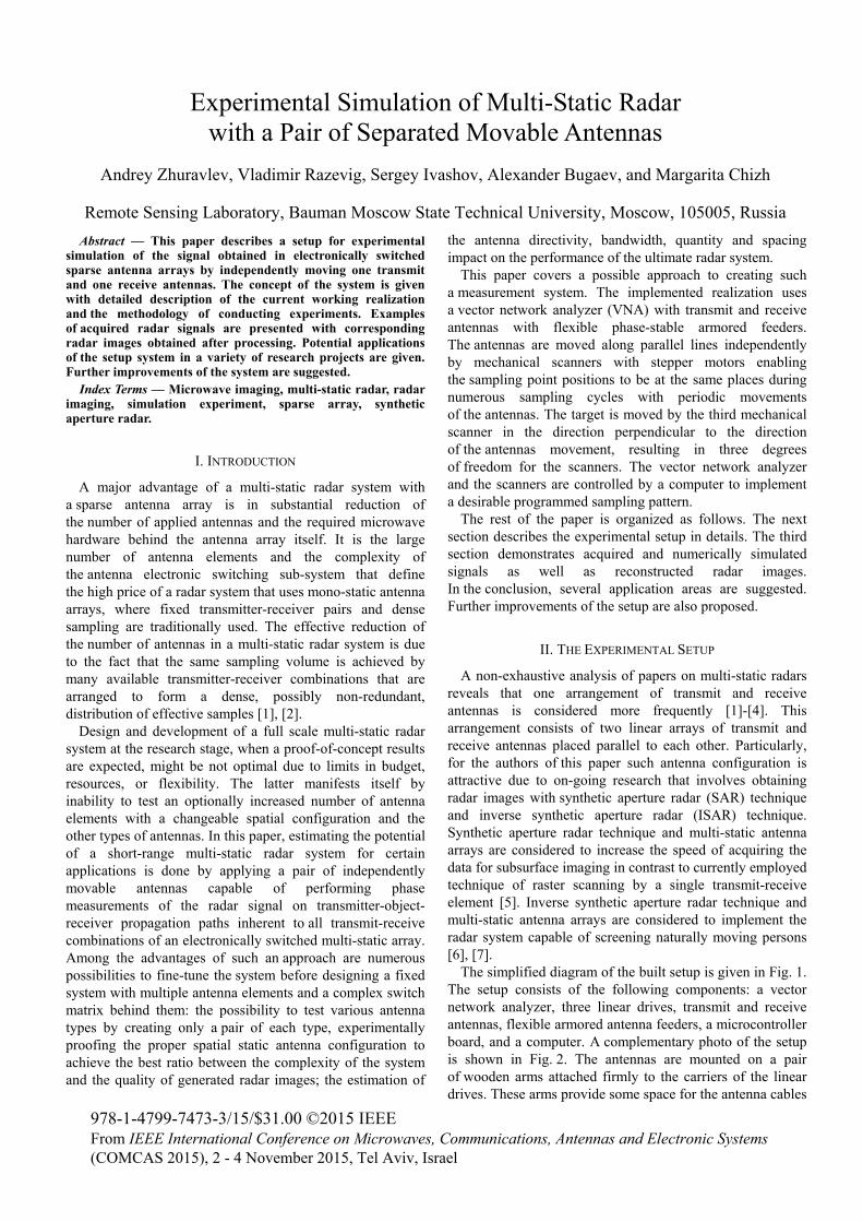
The simplified diagram of the built setup is given in Fig. 1. The setup consists of the following components: a vector network analyzer, three linear drives, transmit and receive antennas, flexible armored antenna feeders, a microcontroller board, and a computer. A complementary photo of the setup is shown in Fig. 2. The antennas are mounted on a pair of wooden arms attached firmly to the carriers of the linear drives. These arms provide some space for the antenna cables
to bend smoothly in motion, and, at the same time, they place antennas at a distance from massive metallic elements of the linear drives to weaken interfering reflections. Each of the three linear drives moves independently either transmit antenna, or the receive antenna, or the target.
The vector network analyzer is connected to local area network (LAN) to receive commands from the computer and provide measurement data. As an additional input signal, the VNA receives the external trigger signal from a microcontroller unit (MCU). Before starting the measurement cycle, the vector network analyzer is preconfigured to measure required parameters (S11 parameter with single antenna, S21 with two antennas) on a desired frequency grid. It is also configured to start a single sweep by the external signal. The MCU is controlled by the same computer and provides real-time signals to the linear drives, giving the trigger signal to the VNA when the current active linear drive carriage passes a given sampling point.
Fig. 1. Simplified diagram of the experimental setup to acquire multi-static radar samples.
The MCU unit is based at an Arduino board with an Atmel ATmega2560 microcontroller. Its embedded software provides command line interface for the personal computer over Universal Serial Bus (USB), generates real-time signals clocked by an internal microcontroller timer for all linear drives to move smoothly without jolts, generates the external trigger signal for the VNA, reports the result of each received and executed command to the computer.
The software on the computer is written in the Python Programming Language and provides the user a command line interface to configure the VNA and the MCU, initiate and fulfill the data acquisition task, and display raw data and system information for debugging the acquisition process.
The description of the computer-side and microcontroller-side software is more technical than scientific and omitted in this paper. The software can be provided to an interested reader upon a request for studying the control realization, code modification and reuse. Fig. 3 illustrates the resulting geometry of the samples during the data acquisition process with the setup.
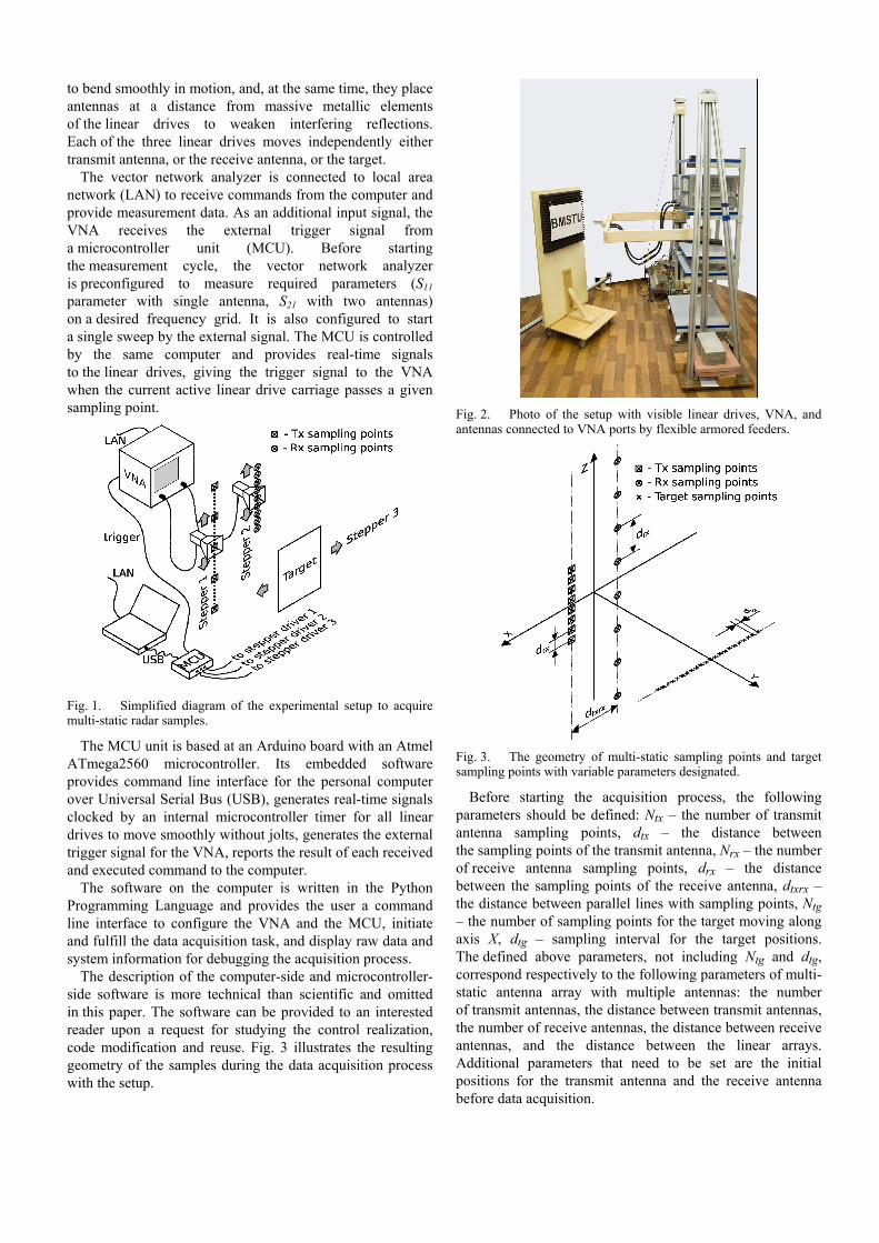
Fig. 2. Photo of the setup with visible linear drives, VNA, and antennas connected to VNA ports by flexible armored feeders.
Fig. 3. The geometry of multi-static sampling points and target sampling points with variable parameters designated.
Before starting the acquisition process, the following parameters should be defined: Ntx – the number of transmit antenna sampling points, dtx – the distance between the sampling points of the transmit antenna, Nrx – the number of receive antenna sampling points, drx – the distance between the sampling points of the receive antenna, dtxrx – the distance between parallel lines with sampling points, Ntg – the number of sampling points for the target moving along axis X, dtg – sampling interval for the target positions. The defined above parameters, not including Ntg and dtg, correspond respectively to the following parameters of multi-static antenna array with multiple antennas: the number of transmit antennas, the distance between transmit antennas, the number of receive antennas, the distance between receive antennas, and the distance between the linear arrays. Additional parameters that need to be set are the initial positions for the transmit antenna and the receive antenna before data acquisition.
The data acquisition process involves placing the receive antenna sequentially into programmed positions and making a continuous scan with the transmit antenna for each position of the receive antenna. In this cycle, the antenna scan patterns can be swapped to minimize the acquisition time. Triggering the VNA to start a sweep happens during a scan at each required transmit (receive if swapped) point along the scan line. During a scan with one antenna the other one remains stationary, while the computer constantly sets the VNA into the wait-for-trigger state and immediately reads the data as soon as the sweep is finished and the data are available. This cycle provides complex samples on a predefined frequency grid for each transmit-receive antenna position combination. The cycle repeats for every position of the target, consuming, for example, an hour for the following parameters: Ntx = 8, dtx = 0.01 m, Nrx = 8, drx = 0.08 m, Ntg = 60, dtg = 0.01 m.
III. NUMERICAL SIMULATION AND SAMPLE EXPERIMENT
The setup may operate in two modes: the mono-static mode, or the multi-static mode, which was described in the previous section and is of primary interest in this paper. Upon acquisition, the data samples are given as four-dimensional array of complex values E(if, itx, irx, itg), where if, itx, irx, itg are the indices for frequency, transmit antenna position, receive antenna position, and target position respectively. Visualizing the acquired multi-static data in the form of an image requires rearranging them so, that the adjacent elements in the image correlate significantly. One such technique uses sorting of z-coordinates of effective sample positions zeff(itx, irx) = (ztx(itx)+zrx(irx))/2, while keeping track of associated indices (itx, irx). Then, the image can be obtained by arranging E(if, itx, irx, itg) for a fixed frequency in the same order as zeff(itx, irx) values, which gives a column of Ntx×Nrx values for each target position. This procedure is performed for each frequency, resulting in a stack of images, with one image for each frequency. With function E being complex, its real/imaginary part or amplitude is displayed as an image with its height equal to Ntx×Nrx and its width equal to Ntg.
Fig. 2 shows an example of a test target, made of foil-cut letters forming the abbreviation “BMSTU”, which stands for Bauman Moscow State Technical University. This target was used in the experiment to assess the capability of the setup to give a radar image. The word is 40 cm wide and 8.5 cm high. This target was placed at the distance of 28.5 cm, while the multi-static samples (S21 parameters as complex values) were acquired for vertical polarization with the following parameters: Ntx = 8, dtx = 0.01 m, Nrx = 8, drx = 0.08 m, Ntg = 71, dtg = 0.01 m. The frequency grid had three frequencies (Nf = 3): 15.55, 15.57, and 15.59 GHz. To compensate for various antenna coupling, resulting from relative motion of the antennas and bending antenna feeders, the multi-static samples, corresponding to all multi-static combinations for the used frequency grid, were acquired with the target absent and the microwave absorption panel left.
The algorithm that was used to obtain numerically simulated multi-static radar samples and the reconstruction of radar image is given in [8], [9]. Fig. 4 shows the simulated and experimental multi-static samples (the amplitude of measured S21 parameter with compensation for antenna coupling) rendered as image according to the technique given above. The images have Ntx×Nrx rows and Ntg columns. The parameters of the simulation and experiment in Fig. 4 are listed at the end of Section II.
Fig. 4. Numerically simulated (left) and experimentally obtained (right) multi-static data samples for the frequency f = 15.55 GHz.
A close resemblance of the numerically simulated and experimentally obtained data is explained by simplicity of the target with a flat surface. For such targets, the single scattering model used in numerical simulations gives good results. The influence of extraneous reflections on the experimental image is minimized by the microwave absorption material on which the target was placed.
The radar images, obtained from demonstrated numerically simulated and experimentally obtained data by the back projection algorithm from [8], [9], are shown in Fig. 5.
Fig. 5. Reconstructed radar images for numerically simulated (left) and experimentally obtained data (right).
A good correspondence between numerically simulated and experimentally obtained data for both raw samples and reconstructed radar images evidences that the approach with linear drives is feasible to experimentally simulate electronically switched antenna arrays. It was observed during development and debugging the setup that the success of image reconstruction is very sensitive to precise repeatability of the sampling points positions during numerous cycles of the linear drives. The next session suggests possible applications of the described setup in several on-going research projects.
IV. CONCLUSION
The main objective of the presented work, involving integration of a VNA with three mechanical scanners, was to acquire multi-static radar samples without making an electronically switched array and leave possibility to vary such key parameters as the number of transmit and receive
antenna elements in experimentally simulated linear antenna arrays, the spacing of antenna elements, and the distance between transmit and receive antenna arrays. Additionally, the performance of different antenna types can be experimentally assessed by having just a pair of each type, or, alternatively, the requirements on the specific antenna type can be established on the basis of experiments with omnidirectional antennas and numerically shaping its directivity pattern when calculating radar images.
The developed setup is used or is planned to be used in a variety of on-going projects in the Remote Sensing Laboratory at BMSTU that are listed and commented below.
A. Estimating performance of MIMO-arrays for subsurface imaging
The attractive quality of multi-static electronically switched antenna arrays is in its ability to simplify the hardware part of an imaging radar system and putting the increased load of computations to a data processor, which makes the system cheaper in comparison to a radar system with an antenna array of closely packed transmit-receive antennas. Doing this, the speed of data acquisition increases, and the quality of generated images does not suffer. The described setup can serve as a proofing tool to test designs of radar imaging systems based on multi-static antenna arrays for a variety of applications: non-destructive testing of materials, including composites. See for example [9], [10].
B. Personnel screening system with inverse aperture
In our previous works [6], [7] it was suggested to use the relative motion of a walking person in the vicinity of vertically oriented antenna arrays to create an inverse synthetic aperture and ultimately reconstruct a radar image with concealed objects on the moving subject. The setup described in this paper will help moving from numerical simulations given in these works to simulation experiments. It these experiments it is planned to use the stop motion animation technique. Some results of our first experimental approach using the setup from this paper are reported in [11].
C. Vital signs monitoring
Using multi-static antenna arrays may be advantageous in remote monitoring of the vital signs: breathing and heartbeat. Because multiple antennas allow adaptive beam-forming resulting in increased signal-to-noise ratio, it seems advantageous to use the described setup and the referred above stop motion technique to assess the performance of a multi-static system for this particular purpose. In relevant experiments the incremental linear motion of the target can be changed to incrementally periodic motion, achieved by stepper motors or servos. Our current activity on this topic, presently without using the described setup, is reported in the proceedings of this conference [12], [13].
The setup presented here can be modified in the following several ways. It is possible to employ multiple antennas and RF-switches and even engage all four available ports of the VNA. This realization will require control of the switches instead of the linear drives and starting
a sweep for each transmit-receive antenna combination. This should significantly decrease the data acquisition time. Another possibility is to use lightweight elements on the linear drives: frequency synthesizer and receiver synchronized with each other by a 10 MHz link over a flexible cable, so that the pair of movable antennas will allow more precise phase measurements eliminating the influence of flexible feeders.
ACKNOWLEDGEMENT
Support for this work was provided by the Russian Science Foundation, project #15-19-30012.
REFERENCES [1] A. J. Kirschner, U. Siart, J. Guetlein, and J. Detlefsen, “MIMO
radar arrays with minimum redundancy: A Design Method,” Proc. of SPIE 8892, Image and Signal Processing for Remote Sensing XIX, 88921W, October 17, 2013.
[2] D. M. Sheen, and T. E. Hall, “Reconstruction techniques for sparse multistatic linear array microwave imaging,” Proc. SPIE 9078, Passive and Active Millimeter-Wave Imaging XVII, 90780I, June 9, 2014.
[3] T. Counts, A. C. Gurbuz, W. R. Scott, J. H. McClellan, and K. Kim, “Multistatic ground-penetrating radar experiments,” Geoscience and Remote Sensing, IEEE Transactions on, vol. 45, no. 8, pp. 2544-2553, August 2007.
[4] O. Ojowu, Y. Wu, J. Li, and L. Nguyen, “SIRE: a MIMO radar for landmine/IED detection,” Proc. SPIE 8714, Radar Sensor Technology XVII, 87140O, May 31, 2013.
[5] A. Zhuravlev, S. Ivashov, V. Razevig, I. Vasiliev, and T. Bechtel, “Shallow depth subsurface imaging with microwave holography,” Proc. SPIE 9072, Detection and Sensing of Mines, Explosive Objects, and Obscured Targets XIX, 90720X, May 29, 2014.
[6] A. Zhuravlev, S. Ivashov, V. Razevig, I. Vasiliev, and T. Bechtel, “Inverse synthetic aperture radar imaging for concealed object detection on a naturally walking person,” Proc. SPIE 9074, Sensors, and Command, Control, Communications, and Intelligence (C3I) Technologies for Homeland Security and Homeland Defense XIII, 907402, May 29, 2014.
[7] A. Zhuravlev, V. Razevig, I. Vasiliev, S. Ivashov, and V. Voronin, “ISAR for concealed objects imaging,” Proc. SPIE 9401, Computational Imaging XIII, 94010I, March 13, 2015.
[8] V. Razevig, V. Chapursky, S. Ivashov, and A. V. Zhuravlev, “Numerical analysis of mono-static and multi-static SAR images in microwave personnel screening systems,” to be appeared in IEEE Antennas and Propagation Magazine in 2015.
[9] A. Zhuravlev, V. Razevig, S. Ivashov, A. Bugaev, and M. Chizh, “Experimental Comparison of Multi-Static and Mono-Static Antenna Arrays for Subsurface Radar Imaging,” (in proceedings of this conference).
[10] S. Ivashov, V. Razevig, I. Vasiliev, A. Zhuravlev, T. Bechtel, and L. Capineri, “Microwave Holography for NDT of Dielectric Structures,” (in proceedings of this conference).
[11] A. Zhuravlev, V. Razevig, and S. Ivashov, “Microwave Imaging of Moving Subjects by Combined Use of Video-tracker and Multi-static Radar,” (in proceedings of this conference).
[12] L. Anishchenko, E. Gaysina, and S. Ivashov, “Comparisson of 4 GHz and 14 GHz SFCW radars in measuring of small laboratory animals vital signs,” (in proceedings of this conference).
[13] S. Churkin, and L. Anishchenko, “Millimeter-wave radar for vital signs monitoring,” (in proceedings of this conference).