Experimental study of a free and forced swirling jetF. Gallaire,a) S. Rott, and J.-M. ChomazLaboratoire d’Hydrodynamique (LadHyX), CNRS, E´cole Polytechnique, 91128 Palaiseau Cedex, France
~Received 4 February 2004; accepted 3 April 2004; published online 1 July 2004!
Vortex breakdown is a widespread phenomenon thaencountered in aeronautical industrial applications as weatmospheric conditions. It is known to alter considerablyflow characteristics resulting in either desirable features sas flame-holders in combustion devices or undesirable csequences, for instance on delta-wings as reviewed in Ror 2. In the latter flow-configuration, the high technologicissue at stake has motivated researchers to develop costrategies~see Ref. 3 for a review!. But only a few studieshave dealt with the control of the more academic experimtal setups in tubes and free swirling jets. These floconfigurations have enabled the discovery of a large varof flow-states4 where helical and axisymmetric breakdoware in competition. Since there is no general agreemenwhether vortex breakdown is basically an axisymmetric pcess or how helical modes contribute in the breakdown pcess, we examine the response of a swirling jet to helperturbations in both the prebreakdown and the breakdregime as defined in Ref. 5.
A recent study by Panda and McLaughlin6 was aimed atdetermining the influence of swirl on the amplificationunstable modes in a free swirling air jet at Reynolds numbabove Re520 000 in the regime preceding vortex breadown. In the unforced regime, these authors establishedabsence of any streamwise growth of the perturbations.acoustic forcing device was then arranged circumferentiaround the jet axis, consisting of four large loudspeakVarious phase combinations between speakers were posand different instability modes could be excited, developinto organized structures consisting of both axisymme(m50) and bending modes (umu51).
The present study, after presenting some new meas
a!Present address: Laboratoire J.-A. Dieudonne´ CNRS, Universite´ de NiceSophia Antipolis, Parc Valrose, F-06108 Nice Cedex 02, France. Electrmail: [email protected]
2901070-6631/2004/16(8)/2907/11/$22.00
Downloaded 07 Sep 2004 to 134.74.76.13. Redistribution subject to AIP
isaseh
n-. 1ltrol
--ty
on--
aln
rs
hen
lys.blegc
re-
ments of the free swirling jet experiment developed by Blant, Chomaz, and Huerre7 at LadHyX, describes the response of the swirling jet to various time-dependeazimuthal perturbations generated at the nozzle exit. Inprebreakdown stage, the flow is shown to respond mosttensively at substantially higher frequencies than that ofnatural mode in the absence of forcing. In contrast, vorbreakdown occurs at the same value of the swirl parameno matter what frequencies or azimuthal modes are appto force the flow.
The paper is organized as follows. Section II briefly prsents the experimental setup and forcing device, whilediagnostic tools are described in Sec. III. Section IV is dvoted to a description of the flow states in absence of forcwhereas the forced experiments are analyzed in Sec. V,a final discussion concluding the paper.
II. EXPERIMENTAL SETUP
A. Background
The present experimental study makes use of the sexperimental apparatus as the study of Billantet al.7 andLoiseleux and Chomaz5 and we therefore briefly review theimain results. Billantet al.7 thoroughly measured the axiaand azimuthal velocity profiles at the nozzle exit using tlaser Doppler velocimetry~LDV ! technique. The azimuthaprofile was characterized by a core in nearly solid bodytation with a rapid decrease to a zero azimuthal velocitysociated to an outer annulus of negative vorticity. Suchshielded vortex is usually referred to as an isolatedscreened vortex and is known to promote both the axisymetric centrifugal instability as well as the destabilizationazimuthal modes resulting from the Kelvin–Helmholtz insbility associated to the azimuthal shear, i.e., to the ravariation of the azimuthal velocity in the radial direction~seeRef. 8 for a review!. This contrasts with the celebrate
2908 Phys. Fluids, Vol. 16, No. 8, August 2004 Gallaire, Rott, and Chomaz
FIG. 1. Experimental setup and PIV inthe horizontal plane.
rtofntf tloc
a
vth
tiurserb
yp-hea
teey
-ie
that
ntal-
ta-e-the
inigu-
oe
nce
de-
thently.
Lamb–Oseen vortex with single-signed axial vorticity. Futhermore, the axial velocity profile was seen to presenmild axial shear and a velocity overshoot in the vicinitythe axis of the jet which increases with the swirl. Billaet al.7 argued that this phenomenon is a consequence ononlinear interaction between the axial and azimuthal veity components in the contraction nozzle.
Flow-visualizations were carried out using longitudinand cross-sectional laser induced fluorescence~LIF! tech-niques. This experimental technique reveals most of the elution of the flow as the swirl parameter is increased. InReynolds number range 300<Re<1200, Billantet al.7 dem-onstrated that the swirl number, as defined in Eq.~1!, wasindeed an adequate control parameter for the determinaof the onset of vortex breakdown. Vortex breakdown occfor a swirl setting ofS5Sc;1.3, for all Reynolds numberconsidered. Four distinct types of vortex breakdown widentified. In addition to the steady and precessing bubvortex breakdown types, evidence was given of a new tof vortex breakdown, the cone~both in its steady and precessing form!. The LDV technique was used to document taxial and radial velocity field in the case of a bubbleRe;670.
Striking helical structures were observed for paramesettings prior to vortex breakdown, independent of the Rnolds number. Helical structures of wavenumberm52 ~tri-dent! andm53 ~celtic cross! were observed. They were observed to rotate at very low or nearly vanishing frequenc
and small axial wavenumbers corresponding to a large pitc
Downloaded 07 Sep 2004 to 134.74.76.13. Redistribution subject to AIP
-a
he-
l
o-e
ons
elee
t
r-
s
of the helix. The sense of their winding was the same asof the rotation of the jet.
In a related study making use of the same experimedevice, Loiseleux and Chomaz5 focused on the early development of the instabilities at Re51490, immediately at thenozzle exit. Adequate image processing~as described inmore detail in the next section! enabled them to distinguishbetween three flow regimes. The first regimeSP@0;0.6# ischaracterized by the axisymmetric Kelvin–Helmholtz insbility very reminiscent of the nonswirling round jet. Throll-up of the Kelvin–Helmholtz rollers is precisely the feature which prevents quantitative measurements based onLIF visualizations further away from the nozzle exit, sincethat case, the radius of the jet cannot be defined unambously. The second [email protected];1# is characterized bothby the axisymmetric Kelvin–Helmholtz instability but alsby anm512 co-rotating helical instability. The last regimwhich precedes breakdownSP@1;1.3# is very unstationaryand irregular. Only Fourier transforms revealed the preseof an m521 counter-rotating structure.
B. Experimental setup
The experimental setup used in this study has beenscribed in Ref. 7 and is shown schematically in Fig. 1.
The main characteristic of the apparatus resides infact that rotation and advection are generated independe
hThis leads naturally to the definition of two independent non-
license or copyright, see http://pof.aip.org/pof/copyright.jsp
or
nevm
ie
izr iicreerin
nl
d
igin
s
mxio
he
ent
res-hehasf theusnts
a-are
ys-ra-iza-Inser-
deoss-nt
280
e.,Thisndter-
vala-theuster isngsora.eatingwein-
to
by
e atar-e an
2909Phys. Fluids, Vol. 16, No. 8, August 2004 Experimental study of a free and forced swirling jet
dimensional parameters. The swirl number is defined accing to
S52Uu~r 5R/2!
Ux~r 50!. ~1!
The swirl numberScharacterizes the intensity of the rotatiowith respect to the axial advection. The Reynolds numbcharacterizing the advection, is based on the maximumlocity of the jet in the absence of rotation and on the diaeter of the jet according to
Re52Ux~r 50,S50!R
n. ~2!
The forcing device is presented in Fig. 2. As in Ref. 9consists of a forcing box divided into six cells of the samsize filled with water. Each cell has a small aperture of s2 mm which is near the nozzle and through which watepumped in or out. Each cell is connected to a pulsing devby a tube filled with water. Different pulsing devices weused. Loudspeakers have the advantage of a precise detnation of the forcing amplitude and offer a total freedomthe choice of the actuator signal. However, they work ofor frequencies higher than 5 Hz.
For forcing frequencies less than 5 Hz, we developecam shaft controlling syringes~Fig. 2!; this has the restric-tion of imposing periodic signals. The amplitude of the snal can be varied by changing the interaxis distance, withlimited range of amplitudes.
Because of the finite number of forcing points, theforcing devices can only excite modesumu<6. Furthermore,whenever a modem is forced, the modem26 is also forced.The modes are thereby forced in pairs~0!, ~11,25!, ~12,24!, ~13,23!, ~14,22! and ~15,21!.
For either a given amplitude of the loudspeaker mebrane motion or a given value of the cam shaft interalength, the forcing device provokes a forcing at constant v
FIG. 2. Forcing device.
ume for any value of the frequencyv. As a consequence, the
Downloaded 07 Sep 2004 to 134.74.76.13. Redistribution subject to AIP
d-
r,e--
t
ese
mi-
y
a
-a
e
-sl-
side-jet velocity increases linearly withv. We have thereforeverified that the forcing velocity never exceeds 1% of tmean axial velocity.
III. DIAGNOSTIC TOOLS
Two experimental techniques are used in the presstudy. Particle image velocimetry~PIV! has been used todescribe the dynamical flow-states. Laser induced fluocence~LIF! in the cross-sectional plane immediately at tnozzle exit together with sequential image processingalso been used in order to characterize the response oswirling jet to a time-periodic forcing. The same continuo5 W argon laser is used for the global PIV measureme~together with an opto-acoustic shutter! and for the LIFcross-sectional images.
A. PIV
Since the velocity fields are three-dimensional, PIV mesurements require precise parameter settings whichbriefly described herein. We use the PIV FlowMaster3 stem manufactured by LaVision which consists of an ultsensitive digital camera by Kodak, a hardware synchrontion unit and a software for the correlation algorithm.addition, we use an opto-acoustic shutter to produce lapulses from a continuous laser.
The PIV works in double-frame/double-exposure moin the sense that each flow evaluation results from the crcorrelation of two physical frames exposed at two differelaser flashes. The resolution of the CCD camera is 131084 with a sensitivity of 12 bits~i.e., 4096 light intensitylevels!. The acquisition frequency of the camera is 4 Hz, i.the camera shoots a pair of frames four times a second.acquisition frequency is too low for dynamical studies aPIV is therefore devoted in our experiment to the characization of the flow-states.
The two frames are separated by the time interdt560 ms, which is one of the most important control prameters. This time interval is chosen so as to minimizenumber of in-plane and cross-plane lost particles but malso remain greater than the exposure time. Since our lasonly 5 W, the exposure time is chosen relatively lotexp54 ms, in order to illuminate the camera sufficientlyas to make the most out of the high sensitivity of the cameThis exposure time is a compromise between having a nimage with steady particles and no streaks and havenough light. In order to obtain as much light as possibleuse a multimode fiber. At the end of the fiber, a set of cyldrical lenses produces a laser sheet of thicknessdz. Theselection ofdz is a trade-off: it seeks simultaneouslymaximize the number of illuminated particles~proportionalto dz), to maximize the intensity received and reflectedeach particle~proportional to 1/dz) while also to minimizethe number of lost out-of-plane particles~proportional to1/dz). The density of particles is then chosen so as to havleast three particles in the interrogation window. The pticles are chosen to be as bright as possible and to havapproximate size of 232 pixels, thereby diminishing thepeak-locking effect.10 We use TiO2 particles of mean diam-
eter 200 microns.
license or copyright, see http://pof.aip.org/pof/copyright.jsp
2910 Phys. Fluids, Vol. 16, No. 8, August 2004 Gallaire, Rott, and Chomaz
FIG. 3. ~Color! Velocity and color coded vorticity fieldsin a transverse plane measured with PIV atS50.8,Re5900, andX50.6.
FTtiv
reh
dh
thes
himThssat
tioin
almcexite
edngfeys
ur-taysor-ofata-er-hist ofar
am
r-e
a
ni-
xit
The cross-correlations are evaluated with standard FThe flow fields are calculated by means of an adaptamultipass algorithm which gradually decreases the sizethe interrogation windows to estimate the shift from thesults at the previous steps for better window-matching. Tinitial interrogation windows are 1283128 and the final onesare 32332 with an overlap of 50%. The final algorithm useconsists of a sub-pixel displacement evaluation througthree point Gaussian cross-correlation peak fitting.
For velocity measurements in the streamwise planecamera and laser sheet are easily aligned with a symmplane of the swirling jet, whereas for measurements in crosectional planes, we use a mirror leaning at 45 degrees wavoids parallax errors which would have occurred if the caera lens had been tilted with respect to the laser sheet.method nevertheless presents several drawbacks: the loluminosity during the optical path in the seeded water,well as the necessity to focus the camera and to calibrateimage each time the cross-sectional streamwise locaX5x/D is varied. Figure 3 depicts a typical velocity fieldthe transverse plane just at the nozzle exitX50.6 forRe5900 andS50.8. In addition, the corresponding axivorticity component is plotted with pseudocolor on the saimage. The vorticity calculated via discrete finite differenformulas complemented by a Gaussian filter shows the etence of an annulus of opposite vorticity screening the vor~Fig. 3!.
B. Spatio-temporal diagrams
Although LIF is generally used to provide qualitativinsights, Loiseleux and Chomaz5,9 have also demonstratehow to extract quantitative results from LIF movies, usithe same experimental apparatus. We take advantage ofact that, if the tracer is homogeneously mixed in the honcomb before entering the contraction, the dye delineate
vorticity surface at the nozzle exit. If viscous effects are
Downloaded 07 Sep 2004 to 134.74.76.13. Redistribution subject to AIP
s.e
of-e
a
etrys-ch-isin
shen
e
s-x
the-a
neglected, the Kelvin theorem specifies that a vorticity sface evolves as a material surface. The dye interface stherefore a vorticity surface until far downstream where crugation of the surface is strong enough for the diffusionvorticity to be significant. Following the dye perturbationsshorter timescales than vorticity diffusion provides informtion about the vorticity sheet deformations which charactize the intensity and development of flow-perturbations. Tcontrasts to flow visualizations based on a single filamendye at the swirling jet centerline which is not a particulvorticity line ~except if the centering is perfect!.
Figure 4 displays a cross-plane LIF cut at a downstrestation X51 in the case ofS50.86 and a forcing of them522 mode at nondimensional forcing frequencyv f57~see the next section!. In this case, the double helix distubance~black arrow! rotates in time in the direction oppositto that of the underlying swirling jet~white arrow!. The ra-dial position of the dye interface is first extracted out ofmovie as a function of the cylindrical anglea and timet viaimage-processing built into theNIH Imagesoftware. In orderto avoid roll-up of the dye and to guarantee a unique defi
FIG. 4. Transverse cut produced by LIF; Re51490, S50.84, X51;m522 forcing atv f57. The dashed line corresponds to the nozzle e
radius.
license or copyright, see http://pof.aip.org/pof/copyright.jsp
aluhe
–ical-a
ta
exd
ioThinth
itsti-–here
ths.in
ge
re-
ise-
e
me-
ones
rsbleing
ate,
edfhevi-
n toeldthethe
e.
ilst
r-
ve-
citye
e-e
,n-
sothal
gr
2911Phys. Fluids, Vol. 16, No. 8, August 2004 Experimental study of a free and forced swirling jet
tion of the radius functionr (a,t), the positionX of the lasersheet is kept close enough to the nozzle exit, resultinggeneral in values ofX less than 1. Typical spatio-tempordiagrams are then obtained as shown in Fig. 5 for theforced case atS50.86, where the gray-level represents tradial deformation of the jetr (a,t) as a function of the anglea and timet.
On such a spatio-temporal diagram, the KelvinHelmholtz jet instability corresponding to axisymmetrmodes (m50) is visible as the horizontal stripes. Azimuthwaves or instabilities (mÞ0) are readily identified by oblique stripes. This enables a precise determination of themuthal wavenumberm as well as the phase-velocityvf .When the swirl number is in the second regime 0.6,S,1defined by Loiseleux and Chomaz,5 two or three obliquestripes appear in addition to the characteristic horizonstripes corresponding to the development ofm52 or m53on top ofm50 modes. The phase velocity of thesem52 orm53 mode is lower than of the rotation rate of the vort~about 1
10! and proportional to the swirl number. Gallaire anChomaz11 have recently proposed a theoretical explanatto the double-helix mode selection in the second regime.double-helix can be understood as a nonlinear self-sustaglobal mode relying on the absolutely unstable nature offlow at the nozzle exit.
IV. FLOW STATES IN ABSENCE OF FORCING
A. Weakly rotating regime
Figure 6~a! represents the measured meridional velocof the nonswirling jet which is representative of the firregime 0<S<0.6. As for nonrotating jets, the flow is domnated by the development of axisymmetric KelvinHelmholtz rings corresponding to the waviness of tstreamlines and of the axial velocity contours. The corsponding transverse vorticity fieldh is shown in Fig. 6~d!and demonstrates the rolling up of vorticity associated toformation of Kelvin–Helmholtz rings. Throughout Fig6~a!–6~c!, the color code associated to the axial velocity
FIG. 5. Typical spatio-temporal diagram. The radius is represented as alevel in thea2t spatio-temporal plane.
tensity is depicted in Fig. 6~a! and is rescaled for each sub-
Downloaded 07 Sep 2004 to 134.74.76.13. Redistribution subject to AIP
in
n-
zi-
l
neede
y
-
e
-
figure respectively, so as to cover the full ran0<uUxu<uUxumax whereuUxumax5max(uUxu) is the maximumabsolute value of the axial velocity over the whole corsponding field. Along the same lines, throughout Figs. 6~d!–6~f!, the color code associated to the azimuthal vorticitydepicted in Fig. 6~d! and is rescaled for each subfigure rspectively, so as to cover the full range2hmax<h<hmax,wherehmax5max(uhu) is the maximum absolute value of thvorticity over the shown field.
B. Trident state
The second regime 0.6<S<1 is characterized by thedevelopment of a double spiral mode that appears on aridional LIF image as a trident@see Fig. 7~a!#, since the lasercuts the middle of the spiral and both arms that developthe side. The velocity distribution obtained from PIV imagshows similar features as seen in Fig. 6~b! obtained forS51.35 and Re5900. The high axial velocity region appeasplit in three as a result of the development of the douspiral. The perturbation corresponding to the remainm50 modes produces roll up of vorticity@as seen in Fig.6~e!# in each of the arms. This state is not a breakdown stsince no stagnation point is present!
C. Breakdown cone
In Fig. 6~c!, the transverse velocity field is representfor a swirl number ofS51.35 and Reynolds number oRe5900. This velocity field elucidates the structure of tconical breakdown in complete agreement with the LIFsualizations of Billantet al.7 reproduced in Fig. 7~b!. Whatwas assumed to be a stagnation point is effectively seestagnate. Further downstream in the cone, the velocity fiis remarkably concentrated into a thin layer. The angle ofcone here is approximately 100°, in good agreement withresults of Billantet al.7
Still more insight can be gained while computing thvorticity field in thez-direction. Results are depicted in Fig6~f! for the same parameter settings as in Fig. 6~c!. Positivevorticity values are depicted in red, negative in blue, whthe hue ~ranging form light to dark! reveals the absolutevalue of the vorticity. This figure should not be misintepreted, since it represents thez-vorticity in a full meridionalsection; only the right part corresponds to the azimuthallocity field for positive radiir ~at an azimuthal angle of 0!whereas the left part corresponds to the azimuthal velofield for negative radiir ~and therefore to the opposite of thvorticity at the azimuthal angle of 180°!. The axisymmetricstructure of the cone suggested by Billantet al.7 is demon-strated since the left part of the velocity field is axially rlated by reflection to the right part. In the following, wcomment on the right part of Fig. 6~f! corresponding to theusual convention of positiver. Upstream from breakdownjust at the nozzle exit, the vorticity is positive and concetrated in the jet shear layer.
The most striking fact is that vortex breakdown is alaccompanied by substantial generation of negative azimu
ay
vorticity. There is indeed a mechanistic explanation of vortex
license or copyright, see http://pof.aip.org/pof/copyright.jsp
2912 Phys. Fluids, Vol. 16, No. 8, August 2004 Gallaire, Rott, and Chomaz
FIG. 6. ~Color! Longitudinal velocity field and associated intensity of the axial component of velocity@~a!–~c!# and transversez-vorticity componenth@~d!–~f!# in the three regimes.~a! and ~d! Regime I: longitudinal velocity field andz-vorticity component in a streamwise plane measured with PIV;S50;Re51200.~b! and ~e! Regime II: longitudinal velocity field andz-vorticity component in a streamwise plane measured with PIV;S50.8; Re5900. ~c! and~f! Regime III~cone type breakdown!: longitudinal velocity field andz-vorticity component in a streamwise plane measured with PIV;S51.35; Re5900. Notethat the velocity scale varies from one subfigure to the other. Furthermore, the color code represented in~a! @respectively in~d!# is specific to each subfigure
isr-r-p
ear-eazi-ichk-
and scales from 0 toUxmax ~respectively from2hmax to hmax).
breakdown proposed by Brown and Lopez,12 Darmofal13 andAlthaus et al.,1 according to which vortex breakdownnothing more than the end result of the tilting of axial voticity due to the swirling motion into negative azimuthal voticity. Furthermore, according to this line of thought, the a
pearance of negative azimuthal vorticity is a prerequisite fo
Downloaded 07 Sep 2004 to 134.74.76.13. Redistribution subject to AIP
-
vortex breakdown, the characteristic stagnation point apping in the flow only when a sufficient amount of negativvorticity has been produced. The appearance of negativemuthal vorticity starts a positive feedback mechanism, whaccelerates its production, finally leading to vortex brea
rdown. This scenario can be in particular identified in the
license or copyright, see http://pof.aip.org/pof/copyright.jsp
2913Phys. Fluids, Vol. 16, No. 8, August 2004 Experimental study of a free and forced swirling jet
FIG. 7. ~a! Trident state observed by Billantet al. ~Ref. 7! at S51.41 and Re5606. ~b! Cone type breakdown state observed by Billantet al. ~Ref. 7! at
isn
riztel
asvendtois-cn
untht
othanheudoseeth
reorona
innse
thelicest
on-of
berrby
heofnd
etric
cted-
tedord-
S51.37 and Re5606.
streamwise development of the breakdown flow. There exanother particular point on the axis, upstream of the stagtion point, which might elsewhere or even better charactethe appearance of vortex breakdown. This point is denoby a 3 in Fig. 6~f!. Upstream of this point, the azimuthavorticity is positive for small values of the radius wheredownstream of this point the azimuthal vorticity is negatiin the vicinity of the axis. In other words, the production adistribution of negative vorticity, when sufficient, is ablechange the sign of the azimuthal vorticity near the axRockwell, Ozgoren, and Sahin14 suggested that vortex breakdown might be more easily diagnosed by monitoring supoints of sign change of vorticity. It was argued that, in cotrast to the stagnation point, which is known to becomesteady as a consequence of the helical instabilities ofbubble itself,15,16 the point of sign change of vorticity mighremain steadier and be therefore easier to identify.
V. FORCED EXPERIMENTS
In spatially developing flow, time-dependent forcing~re-ferred to as the spatial instability approach! is the preferredexperimental methodology, since it provides estimatesspatial growth rates. Our forcing device, in contrast tocorrugated nozzle used by Lasheras, Lecuona,Rodriguez17 in their study of pure jets, can prescribe both tazimuthal wavenumber and frequency. In the present stthe spatial growth rate of the instabilities is, however, naccessible since the saturation of the rings restricts premeasurements toX,1 for forcing frequencies such that thresponse of the swirling jet is large. On the other hand,setup does not allow observation forX closer to the nozzleexit than X50.6. Use of the PIV technique is even morestricted to large perturbation amplitudes and therefwould not give access either to spatial growth rates. We csider instead the amplitude at a given streamwise coordi
X50.6 as a function of the forcing frequency and azimutha
Downloaded 07 Sep 2004 to 134.74.76.13. Redistribution subject to AIP
tsa-ed
.
h--e
fed
y,tnt
e
en-te
mode number. Although the natural structures prevailingthe unforced flow are co-rotating, we consider the respoto co-rotating (m.0) and counter-rotating (m,0) perturba-tions of azimuthal wavenumbers which correspond toobserved modes in the second regime, i.e., double he(umu52) and celtic crosses (umu53). It is emphasized thathroughout the study the sign ofm refers to the propagationin time of the azimuthal disturbance in a cross-plane, in ctrast with theoretical studies where it refers to the signwinding in space of the perturbations. The Reynolds numis kept constant and equal to Re51490 and the swirl numbeto S50.84, a swirl value of the second regime identifiedLoiseleux and Chomaz.5
The forcing frequencyv f is nondimensionalized withthe natural prevailing frequency vnat52vfnat
55031022 rad•s21 as estimated by Loiseleux and Chomaz5 ormeasured on the spatio-temporal diagram from Fig. 5. Treceptivity of the jet is determined through the analysisspatio-temporal diagrams for different azimuthal modes adifferent frequencies in the range 0.5,v f,14 at a distancefrom the nozzle exit ofX50.6 diameter. The intensity of thresponse is then computed as follows. First the axisymmetrend is calculated according to
A0~ t !5^A~ t,a!&, ~3!
where ^•& designates the angular average, and subtrafrom the initial fieldA(t,a) to yield the azimuthal deformation field A(t,a):
A~ t,a!5A~ t,a!2A0~ t !. ~4!
Introducing for any time dependent functionf (t) the tempo-
ral averagef and the standard deviationfI5Af 22 f 2, themean amplitude of the azimuthal field is then estimathrough an angular average of all standard deviations acc
ling to
license or copyright, see http://pof.aip.org/pof/copyright.jsp
se
2914 Phys. Fluids, Vol. 16, No. 8, August 2004 Gallaire, Rott, and Chomaz
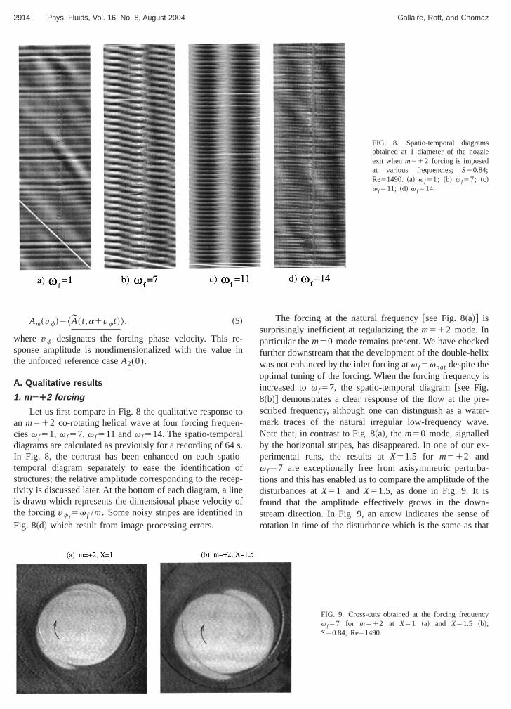
FIG. 8. Spatio-temporal diagramobtained at 1 diameter of the nozzlexit whenm512 forcing is imposedat various frequencies; S50.84;Re51490. ~a! v f51; ~b! v f57; ~c!v f511; ~d! v f514.
rei
tn-l4at
einyin
edelix
is
pre-ter-e.
ex-
a-f the
n-of
Am~vf!5^A~ t,a1vft !&, ~5!
where vf designates the forcing phase velocity. Thissponse amplitude is nondimensionalized with the valuethe unforced reference caseA2(0).
A. Qualitative results
1. mĿ2 forcing
Let us first compare in Fig. 8 the qualitative responsean m512 co-rotating helical wave at four forcing frequeciesv f51, v f57, v f511 andv f514. The spatio-temporadiagrams are calculated as previously for a recording of 6In Fig. 8, the contrast has been enhanced on each sptemporal diagram separately to ease the identificationstructures; the relative amplitude corresponding to the rectivity is discussed later. At the bottom of each diagram, a lis drawn which represents the dimensional phase velocitthe forcingvf f
5v f /m. Some noisy stripes are identified
Fig. 8~d! which result from image processing errors.
Downloaded 07 Sep 2004 to 134.74.76.13. Redistribution subject to AIP
-n
o
s.io-ofp-eof
The forcing at the natural frequency@see Fig. 8~a!# issurprisingly inefficient at regularizing them512 mode. Inparticular them50 mode remains present. We have checkfurther downstream that the development of the double-hwas not enhanced by the inlet forcing atv f5vnat despite theoptimal tuning of the forcing. When the forcing frequencyincreased tov f57, the spatio-temporal diagram@see Fig.8~b!# demonstrates a clear response of the flow at thescribed frequency, although one can distinguish as a wamark traces of the natural irregular low-frequency wavNote that, in contrast to Fig. 8~a!, them50 mode, signalledby the horizontal stripes, has disappeared. In one of ourperimental runs, the results atX51.5 for m512 andv f57 are exceptionally free from axisymmetric perturbtions and this has enabled us to compare the amplitude odisturbances atX51 and X51.5, as done in Fig. 9. It isfound that the amplitude effectively grows in the dowstream direction. In Fig. 9, an arrow indicates the sense
rotation in time of the disturbance which is the same as that
cy
FIG. 9. Cross-cuts obtained at the forcing frequenv f57 for m512 at X51 ~a! and X51.5 ~b!;S50.84; Re51490.
license or copyright, see http://pof.aip.org/pof/copyright.jsp
s
2915Phys. Fluids, Vol. 16, No. 8, August 2004 Experimental study of a free and forced swirling jet
FIG. 10. Spatio-temporal diagramobtained at X51 diameter of thenozzle exit when them522 ~a! andm563 ~b! forcing is imposed at vari-ous forcing frequencies;S50.84;Re51490.
io
jetioth
fo
l
ing
h
w
ct
iur
tuwa
om
-Ie
m-the
ity-
ig.ia-ds
heIF.outes.
theisd in
euper-
chre-rentherror
of the underlying jet. Note the presence of dye filamentatwhich breaks the full symmetry of them512 perturbation.Considering the rotation of the perturbation around thecore, the arms of the double helix present dye filamentaat the rear of the perturbation. This is the manifestation ofso-called stripping or erosion process.
The largest response to the forcing is obtainedv f511 @see Fig. 8~c!# where the helicalm512 wave issynchronized with them50 rollers. In this case, the naturafrequency of them50 mode isv058 close to the forcingvalue, and both waves are strongly affected by the forcWhen the frequency is further increased as forv f514 inFig. 8~d!, the low-frequency natural modem512 appearsagain and is irregular, as if no forcing were applied to tflow. By contrast, the axisymmetricm50 mode responds tothe forcing.
It should finally be noted that the flow does not shoany receptivity to modem524, which is automaticallyforced by the forcing device together with modem512.
2. mÄÀ2 forcing
Figure 10~a! presents spatio-temporal diagrams refleing the response of the flow tom522 forcing at frequencyv f57 andv f511. In both cases, the qualitative responsesignaled by the alignment between the observed structand the forced phase velocity. Still, the naturalm512 helixis identified as a watermark in Fig. 10~a!. Not shown here arethe results at lower and higher frequencies where the nadouble-helix takes over and no response to the forcingfound.
Figure 4~a!, which was introduced in Sec. III in order tdescribe the construction rules of spatio-temporal diagrarepresents a cross-section atX51, v f57 andm522 and itis the complementary picture to Fig. 9~a! at the same streamwise location and frequency but for the opposite mode.Fig. 4~a!, the arrow indicates the direction of rotation of th
Downloaded 07 Sep 2004 to 134.74.76.13. Redistribution subject to AIP
n
tne
r
.
e
-
ses
rals
s,
n
perturbation which is opposite to the background flow. Coparison of both figures suggests that the receptivity offlow is similar for the co-rotativem512 and the counter-rotativem522 at v f57.
Finally, note that the flow does not show any receptivto modem514, which is automatically forced by the forcing device together with modem522.
3. mÄÁ3 forcing
Figure 10~b! represents analog results to those of F10~a! for m563. The checkboard-type spatio-temporal dgrams obtained forv f54.5 demonstrate that the jet responas well to a co-rotative excitationm513 as to counter-rotative excitationm523.
Figure 11 demonstrates the receptivity of the flow to tforcing further downstream through a comparison of a Lcross-section atX51 and atX56. The instantaneous Fig11~b! displays a threefold symmetry. Three arms branchof the jet core and roll up into mushroom-type structurThis structure differs from the natural helices. Figure 7~a!indeed demonstrates that the ends of the two arms ofdouble-helix roll up into single-signed end vortices. Thcontrasts with the mushroom-type end structures observeFig. 11~b!, which reveal axial vorticity of both signs. Wsuggest that the structure could be a consequence of a sposition ofm513 andm523 modes.
B. Quantitative results
Quantitative results are displayed in Fig. 12. For eaazimuthal wavenumber and each forcing frequency, thesponse amplitude has been measured on three diffespatio-temporal diagrams recorded at different times. Tplotted value is the mean of these three values and the ebar their standard deviation.
license or copyright, see http://pof.aip.org/pof/copyright.jsp
cy
2916 Phys. Fluids, Vol. 16, No. 8, August 2004 Gallaire, Rott, and Chomaz
FIG. 11. Cross-cuts obtained at the forcing frequenv f57 and m563 for X51 ~a! and X56 ~b!;S50.84; Re51490.
ngt
orurret irigse
inn
-pr
ooIF
arimangraheth
on-d.n
ded foralf
the
ofzi-ac-ol-
ha-
ga-
theu-ofjetg
orehe
A brief summary of the results is that, whatever forcimode is considered, the response is strongly peaked invicinity of v f58 – 10. For am512 forcing, we therebydemonstrate that the maximum response is obtained ffrequency one order of magnitude higher than the natfrequency. The swirling jet does not respond to forcing fquencies which are either too low or too high. This resulquite surprising since one would have imagined that the pvailing frequency in the unforced case could easily be trgered through external forcing at this precise frequencyting.
Finally, we have examined the response of the swirljet to the forcing of different azimuthal modes and frequecies in the breakdown regime (S>1.3). The breakdown appears insensitive to these control attempts; it seems tovent any instability development. Moreover, forS.1.3, thestagnation point corresponding to vortex breakdown smigrates close to the nozzle exit, thereby inhibiting any Lmeasurements.
VI. DISCUSSION
The main findings of the present experimental studyas follows. PIV measurements in the prebreakdown reghave been conducted which confirm the results of Billet al.7 The vorticity fields obtained from finite differencinof the velocity fields in the cross-sectional plane demonstthe screened nature of the vortex at the nozzle exit. Furtmore, it is seen that vortex breakdown is associated with
Downloaded 07 Sep 2004 to 134.74.76.13. Redistribution subject to AIP
he
aal-se--t-
g-
e-
n
eet
ter-e
appearance of negative vorticity on the jet axis as demstrated by vorticity plots in the longitudinal plane. Forceexperiments at Re51490 andS50.86 have been conductedIt is shown that the receptivity of the jet is very poor whethe forcing is set to the natural prevailing azimuthal moand frequency. In contrast, a strong response is observeboth co-rotating and counter-rotating forced azimuthmodes (m562, m563) for frequencies about one order omagnitude larger than the natural frequency prevailing inabsence of forcing.
A striking result of the study is the extreme robustnessthe vortex breakdown, which remains unaffected by amuthal forcing at the nozzle periphery with the presenttuator. This might be understood in at least one of the flowing manners: according to Squire18 or Wang and Rusak,19
the mechanism leading to vortex breakdown is a core mecnism related to the Kelvin waves~or inertial waves! living inthe core of the vortex. Alternatively, the appearance of netive azimuthal vorticity, claimed by Brown and Lopez12 to beresponsible for vortex breakdown, also takes place nearswirling jet axis. The present actuator is efficient in maniplating the vorticity sheet separation; it acts at the peripherythe vortex. As one would have guessed from nonrotatingexperiments, this type of actuator is efficient in controllininstabilities that develop at the periphery but not in the cof the vortex. This may be the reason for the failure of tpresent forcing device in controlling vortex breakdown.
c-
FIG. 12. Response amplitude to the forcing as a funtion of v f at X50.6 and~a! m512, ~b! m522 and~c! m563; S50.84; Re51490.
license or copyright, see http://pof.aip.org/pof/copyright.jsp
ador
io
,’’
l,’’
tex
a
irl
tex
v.
ri-
si-
’’
h-ffet
ty
alla-
truc-d
nd
2917Phys. Fluids, Vol. 16, No. 8, August 2004 Experimental study of a free and forced swirling jet
ACKNOWLEDGMENTS
The authors wish to thank A. Garcia for his technicassistance and enthusiasm as well as T. Loiseleux, R. GoDiana and L. Tuckerman for helpful suggestions. This wohas benefitted from the financial support by the DirectGenerale de l’Armement ~DGA! under Grant PEA No.99001004707588, ‘‘Eclatement tourbillionnaire.’’
1W. Althaus, C. Bru¨cker, and C. Weimer, ‘‘Breakdown of slender vorticesin Fluid Vortices, edited by S. I. Green~Kluwer Academic, Dordrecht,1996!, Chap. 9, pp. 373–426.
2J. Delery, ‘‘Aspects of vortex breakdown,’’ Prog. Aerosp. Sci.30, 1~1994!.
3A. Mitchell and J. Delery, ‘‘Research into vortex breakdown controProg. Aerosp. Sci.37, 385 ~2001!.
4J. Faler and S. Leibovich, ‘‘Disrupted states of vortex flow and vorbreakdown,’’ Phys. Fluids20, 1385~1977!.
5T. Loiseleux and J.-M. Chomaz, ‘‘Breaking of rotationnal symmetry inswirling jet experiment,’’ Phys. Fluids15, 511 ~2003!.
6J. Panda and D. McLaughlin, ‘‘Experiments on the instabilities of a swing jet,’’ Phys. Fluids6, 263 ~1994!.
7P. Billant, J.-M. Chomaz, and P. Huerre, ‘‘Experimental study of vorbreakdown in swirling jets,’’ J. Fluid Mech.376, 183 ~1998!.
8E. Hopfinger and G. van Heijst, ‘‘Vortices in rotating fluids,’’ Annu. Re
Fluid Mech.25, 241 ~1993!.
Downloaded 07 Sep 2004 to 134.74.76.13. Redistribution subject to AIP
ly-
kn
-
9T. Loiseleux, Ph.D. thesis, Ecole Polytechnique, 1999.10M. Raffel, C. Willert, and J. Kompenhans,Particle Image Velocimetry: A
Practical Guide~Springer, New York, 1998!.11F. Gallaire and J.-M. Chomaz, ‘‘Mode selection in swirling jet expe
ments: a linear stability analysis,’’ J. Fluid Mech.494, 223 ~2003!.12G. Brown and J. Lopez, ‘‘Axisymmetric vortex breakdown. Part 2: Phy
cal mechanisms,’’ J. Fluid Mech.221, 553 ~1990!.13D. Darmofal, ‘‘The role of vorticity dynamics in vortex breakdown,
AIAA Pap. 93-3036~1993!.14D. Rockwell, M. Ozgoren, and B. Sahin, ‘‘Vortex breakdown from a pitc
ing delta wing incident upon a plate: Flow structure as the origin of buloading,’’ J. Fluids Struct.16, 295 ~2002!.
15X. Yin, D. Sun, M. Wei, and J. Wu, ‘‘Absolute and convective instabilicharacter of slender viscous vortices,’’ Phys. Fluids12, 1062~2000!.
16M. Ruith, P. Chen, E. Meiburg, and T. Maxworthy, ‘‘Three-dimensionvortex breakdown in swirling jets and wakes: direct numerical simution,’’ J. Fluid Mech.486, 331 ~2003!.
17J. C. Lasheras, A. Lecuona, and P. Rodriguez, ‘‘Three-dimensional sture of the vorticity field on the near region of laminar co-flowing forcejets,’’ in The Global Geometry of Turbulence~Plenum, New York, 1991!.
18H. B. Squire, ‘‘Analysis of the vortex breakdown phenomenon,’’ inMis-zallaneen der Angewandten Mechanik~Akademie Verlag, Berlin, 1960!, p.306.
19S. Wang and Z. Rusak, ‘‘The dynamics of a swirling flow in a pipe atransition to axisymmetric vortex breakdown,’’ J. Fluid Mech.340, 177
~1997!.
license or copyright, see http://pof.aip.org/pof/copyright.jsp