Experimental verification of modified synthetic discriminant function filters for rotation invariance Max B. Reid, Paul W. Ma, John D. Downie, and Ellen Ochoa A modified binary synthetic discriminant function filter designed to recognizeobjects over a range of rotated viewshas been verified on a laboratory optical correlator. A binary synthetic discriminant function filter has been previously described that will produce a specified correlation response for a set of training images. [See D. A. Jared and D. J. Ennis, "Inclusion of Filter Modulation in Synthetic-Discriminant-Function Construc- tion," Appl. Opt. 28, 232-239 (1989).] In the filter design, the modulation characteristics of the device onto whichthe filter is mapped are included in the synthesis equations. The system of nonlinear equations is then solved using an iteration procedure based on the Newton-Raphson algorithm. The development of the filter-SDF (fSDF) method was driven by the practical concern to make currently available spatial light modulators with limited modulation capabilities functional for distortion invariant pattern recognition. This technique is used to synthesize filters for a binary magnetooptic spatial light modulator (MOSLM),the Sight-MOD produced by Semetex. Two MOSLMs are used in the laboratory correlator, one in the filter plane and one in the input plane. We demonstrate that a single filter produces equal correlation peaks for a sample object (a Shuttle Orbiter in these tests) over in-plane and out-of-plane rotation ranges up to 75°. The correlator is able to track dynamically the shuttle as it moves along a curved path across the input field. Views of the object in between those in the training set are also recognized when training images are sufficiently close in angle (-5° apart). 1. Introduction A binary synthetic discriminant function (SDF) fil- ter has been previously described that will produce a specified correlation response for a set of training im- ages.' Synthetic discriminant function filters are gen- erally complex valued, and cannot be encoded in the type of binary spatial light modulator (SLM) readily available as a commercial product. However, an effec- tive SDF can be encoded on a binary SLM if the modulation characteristics of the device onto which the filter is mapped are included in the filter synthesis equations. The synthetic function produced in this manner is referred to as a filter SDF (fSDF). Simula- tions of fSDF filters on the example of rotation invari- ance have previously shown that one binary encoded filter can produce equal intensity correlation peaks for images of a space shuttle orbiter rotated in-plane over 750, or out-of-plane over -15'.2 The authors are with NASA Ames Research Center, Intelligent Systems Technology Branch, Moffett Field, California'94035. Received 21 August 1989. The fSDF techniques 2 begins with a set of centered training images, t(xy), n = 0,1,...,k, spanning the desired distortion invariant feature range. This image set is used to construct the fSDF, s'(xy), for a given filter modulation. The desired peak correlation re- sponse of s'(xy) is a constant, Cn, for each training image tn(x,y): ff t,,(xy)s'*(xy)dxdy = (tn(xy)s'(xy)) = n (1) where the integral is taken over the area of the input field. The function s'(xy) includes the filter modula- tion, A, through the equation s'(xy) = 9-XrS(XY)]*, (2) wheref is the Fourier transform operator. The pur- pose of the fSDF procedure is to determine the func- tion s(x,y) which solves Eq. (1) given a particular mod- ulation function, At. The function s(xy) is chosen to be a linear combination of the training images: k S(Xy) = E antn(xy). n=O (3) A general fSDF synthesis equation results from substi- tuting Eqs. (3) and (2) into Eq. (1): 10 March 1990 / Vol. 29, No. 8 / APPLIED OPTICS 1209
Transcript
Experimental verification of modified syntheticdiscriminant function filters for rotationinvariance
Max B. Reid, Paul W. Ma, John D. Downie, and Ellen Ochoa
A modified binary synthetic discriminant function filter designed to recognize objects over a range of rotatedviews has been verified on a laboratory optical correlator. A binary synthetic discriminant function filter hasbeen previously described that will produce a specified correlation response for a set of training images. [See
D. A. Jared and D. J. Ennis, "Inclusion of Filter Modulation in Synthetic-Discriminant-Function Construc-tion," Appl. Opt. 28, 232-239 (1989).] In the filter design, the modulation characteristics of the device ontowhichthe filter is mapped are included in the synthesis equations. The system of nonlinear equations is thensolved using an iteration procedure based on the Newton-Raphson algorithm. The development of thefilter-SDF (fSDF) method was driven by the practical concern to make currently available spatial lightmodulators with limited modulation capabilities functional for distortion invariant pattern recognition.This technique is used to synthesize filters for a binary magnetooptic spatial light modulator (MOSLM), theSight-MOD produced by Semetex. Two MOSLMs are used in the laboratory correlator, one in the filterplane and one in the input plane. We demonstrate that a single filter produces equal correlation peaks for asample object (a Shuttle Orbiter in these tests) over in-plane and out-of-plane rotation ranges up to 75°. Thecorrelator is able to track dynamically the shuttle as it moves along a curved path across the input field.Views of the object in between those in the training set are also recognized when training images aresufficiently close in angle (-5° apart).
1. Introduction
A binary synthetic discriminant function (SDF) fil-ter has been previously described that will produce aspecified correlation response for a set of training im-ages.' Synthetic discriminant function filters are gen-erally complex valued, and cannot be encoded in thetype of binary spatial light modulator (SLM) readilyavailable as a commercial product. However, an effec-tive SDF can be encoded on a binary SLM if themodulation characteristics of the device onto whichthe filter is mapped are included in the filter synthesisequations. The synthetic function produced in thismanner is referred to as a filter SDF (fSDF). Simula-tions of fSDF filters on the example of rotation invari-ance have previously shown that one binary encodedfilter can produce equal intensity correlation peaks forimages of a space shuttle orbiter rotated in-plane over750, or out-of-plane over -15'.2
The authors are with NASA Ames Research Center, IntelligentSystems Technology Branch, Moffett Field, California'94035.
Received 21 August 1989.
The fSDF techniques 2 begins with a set of centeredtraining images, t(xy), n = 0,1,...,k, spanning thedesired distortion invariant feature range. This imageset is used to construct the fSDF, s'(xy), for a givenfilter modulation. The desired peak correlation re-sponse of s'(xy) is a constant, Cn, for each trainingimage tn(x,y):
ff t,,(xy)s'*(xy)dxdy = (tn(xy)s'(xy)) = n (1)
where the integral is taken over the area of the inputfield. The function s'(xy) includes the filter modula-tion, A, through the equation
s'(xy) = 9-XrS(XY)]*, (2)
wheref is the Fourier transform operator. The pur-pose of the fSDF procedure is to determine the func-tion s(x,y) which solves Eq. (1) given a particular mod-ulation function, At. The function s(xy) is chosen tobe a linear combination of the training images:
k
S(Xy) = E antn(xy).n=O
(3)
A general fSDF synthesis equation results from substi-tuting Eqs. (3) and (2) into Eq. (1):
For phase-only filters (POFs) and binary phase-onlyfilters (BPOFs), Eq. (4) is a system of nonlinear equa-tions which may be solved using an iterative procedurebased on the Newton-Raphson algorithm. The filtercoefficients, a, are constrained to be real and are ini-tialized to the desired response vector, c, and iteratedbased on the formula
a a + a cn ) (5)
where i is the iteration number, 0i is a damping con-stant, and ml is the modulus of the peak correlationresponse of image t(x,y) with the filter constructedwith ai.
11. Correlator Design
This filter synthesis technique has recently beenverified in the laboratory using 128 X 128 pixel magne-tooptic spatial light modulators (MOSLMs) producedby Semetex for both the input and filters. Binaryphase-only operation is achieved by placing the ana-lyzer after the filter MOSLM perpendicular to thepolarization defined by the input MOSLM polarizer.3The standard 4f optical correlator system is replacedby a more compact three-lens modified 3f system asshown in Fig. 1. A significant reduction from thelength of a standard 4f system can be obtained by usinga five-lens correlator, with one pair of lenses used foreach transform and an additional lens at the filterplane to correct for phase errors.4 In our system, wemaintain the use of two lenses for the first transform,but replace the last three lenses with a single lens at thefilter plane. By performing both the second transformand the correction for any phase errors at the filterplane with a single lens, this configuration simplifiesthe operational difficulty of component spacing andalignment. The total system length is reduced to -2f.
The focal length f is chosen to map the inputMOSLM onto the filter plane with a frequency cutoffequal to v, = 1/2a, where a = 0.076 mm is the MOSLMpixel spacing. For a wavelength of 632.8 nm, the re-sulting value of f = 1168 mm is convenient as it mapsthe values of the discrete Fourier transform (DFT)directly onto the filter MOSLM without scaling. If acutoff frequency other than v, = 1/2a is used, the DFTmust first be scaled before it is written to the filterMOSLM.
The transmittance of the MOSLMs used is fairly low(-5%), and in addition, a high percentage of transmit-ted light is diffracted into higher orders by theMOSLM pixel structure. Simply imaging throughboth light modulators, the intensity of light transmit-ted to the correlation plane is reduced from the inputplane by -6 orders of magnitude. This necessitatesthe use of a silicon intensifier target camera in thecorrelation plane, along with a 35-mW He-Ne laser toprovide sufficient input intensity.
Ro
Input plane: Lenses I & 2: Filter plane: CorrelationMSLM I Fourier Lens 3 and Plane
Transform Pair MSLM 2
Fig. 1. Three lens correlator using magnetooptic spatial light mod-ulators (MSLMs) in the input and filter planes. Lens 3 performsboth phase correction and the inverse transform. The phase errorsneed not be known with precision ahead of time. If the errorspresent in practice require a lens of focal length f" for correction,then the detector in the correlation plane is simply moved to a point
= l/(l/f3- 1/f') from the filter plane. Asf" f in practice, lettingf3 f/2 produces f' f, which is a convenient operational point.
Ill. Procedure
The iterative filter construction is performed direct-ly on the optical correlator under automatic computercontrol. Views of a space shuttle orbiter are stored asbinary images on a Masscomp 5600 laboratory com-puter. Both the input and filter MOSLMs are con-trolled by the computer, and the correlation output isread directly into the Masscomp with a frame grabber.The intensity of the actual optical correlation peaksare used in the iterative algorithm described above todetermine the fSDF coefficients. Constructing thefSDFs on the correlator instead of in a simulation hasthe advantages of using a continuous Fourier trans-form and of compensating for any aberrations presentin the optical system.
We have determined empirically that the output ofthe frame-grabber/camera system varies by -+10%from frame to frame even under controlled lightingand temperature conditions. We attribute this to theinternal circuitry of the camera/frame grabber whichproduces variable gain. Due to this variation, an aver-age of ten measurements is taken of the correlationpeak of each image with the trial filter during eachiteration to avoid making random changes in the fSDFcoefficient which could preclude convergence. Itera-tion is stopped when the peak correlation response foreach image in the training set varies by no more than+5% from the average of all peaks in the set. Insimulations,' it was found that the number of itera-tions required for convergence was generally approxi-mately equal to the number of images in the trainingset. Experimentally, the number of required itera-tions goes up slightly faster than the number of filters,N, due to the statistical error in correlation peak mea-surement. The number of iterations required goes upapproximately as N3/2.
Filters are constructed to provide either in-plane orout-of-plane rotation invariance. For in-plane rota-tion, filters designed to be invariant over distortionranges up to 900 are constructed using training images
. j.* .** .uE. **.. ... ' ' 4> w . ' , Fig. 3. Average fSDF peak and clutter vs in-plane rotation distor-. .. ,*, " .* mu. .tion range. Data points are the average peak (closed squares) and
g _ - -Aclutter (open squares) responses for each image within the distortionX n E n range, measured at every 10. For example, the data points for peak
- oO4-O__ - Am ,< a , 't and clutter at 600 are the average of all sixty-one peak and clutter0000 0° na00 e 00° 0°° ° ° ° 0 0o = o |data points shown in Fig. 2(b). The data are normalized to the peak
0I 0L I t 1 - - :1 Iresponse of a BPOF matched to the shuttle oriented at O.
0 1 0 20 30 4 0 50 6 nal-to-noise ratio which defines noise as the average
Rotation Angle value in the correlation plane outside of the full-widthhalf-maximum of the primary peak. PSR is therefore
ut images (showin g range of rotational views). (b) used as the determining measure of correlation qualitying equal intensity peaks obtained using one fSDF in this work.
filter. Peak (closed squares) and clutter (open squares) data aregiven normalized to the peak response of a BPOF matched filter for
the shuttle at 00.
of the shuttle separated by rotations of 5°. For exam-ple, the fSDF designed for invariance to in-plane rota-tions over a distortion range of 600 is constructed fromthirteen training images. The desired peak correla-tions, c,, are set equal for each rotated image tn(x,y).
After construction, filters are correlated with imagesspanning their entire design range at 10 intervals, in-cluding views of the object inbetween those used in thetraining set. The peak correlation intensity is mea-sured for each input image, along with the peak clutter,or secondary peak intensity. The peak response isdefined to be the intensity of the correlation plane at(xy) = (0,0):
P = Ic(0,0)12. (6)
The secondary peak was defined to be the highestintensity in the correlation plane at points at least 3pixels away from the primary peak, with the additionalcondition that c(x,y) must be a local maximum at thesecondary peak:
C = maxlc(x,y)12 , such that IxI,IyI > 3, (7)
and-=-= 0.ax Oy
The second constraint guarantees that a smooth pri-mary peak base will not be counted as clutter. Theratio of P/C has been termed a peak to secondary ratio(PSR) in the literature.5 The PSR is a much moreconservative measure of correlation quality than a sig-
IV. Results
A. In-Plane Rotation
A typical plot of peak and clutter measured at 1°intervals for an fSDF designed to be invariant to in-plane rotations is shown in Fig. 2(b). This fSDF wasdesigned for invariance over a 600 range using thirteentraining images separated by 50 intervals from 0°-60°.The images at the two endpoints of the distortionrange are shown in Fig. 2(a). Peak and clutter aregiven normalized to the peak response of a BPOF madefrom a matched filter ofthe shuttle at 00. The figureshows that the peak response of the fSDF remainsfairly constant over the full distortion range, includingthose angles inbetween the training images. Thepeaks are easily distinguishable with simple intensitythresholding, as the PSR remains nearly constant at~2.
Average peak and clutter data for fSDFs with distor-tion ranges up to 900 are summarized in Fig. 3. Thesedata were acquired by making a filter from the 0 and 50images and testing it on images from 0-5° at 10 inter-vals, then making a filter from the 0, 5, and 100 imagesand testing it on images from 0-10° at 1 intervals,continuing to a filter made from the 0,5,10,.. .,90°images and testing it on images from 0-90° at 10 inter-vals. The values in Fig. 3 are normalized to the re-sponse of an fSDF with 00 range, i.e., a BPOF matchedfilter. Data are given as the average response of allimages in the distortion range measured at each 10interval. For example, the data points at 600 in Fig. 3are the average of all sixty-one peak and clutter datapoints shown in Fig. 2(b). While the peak response
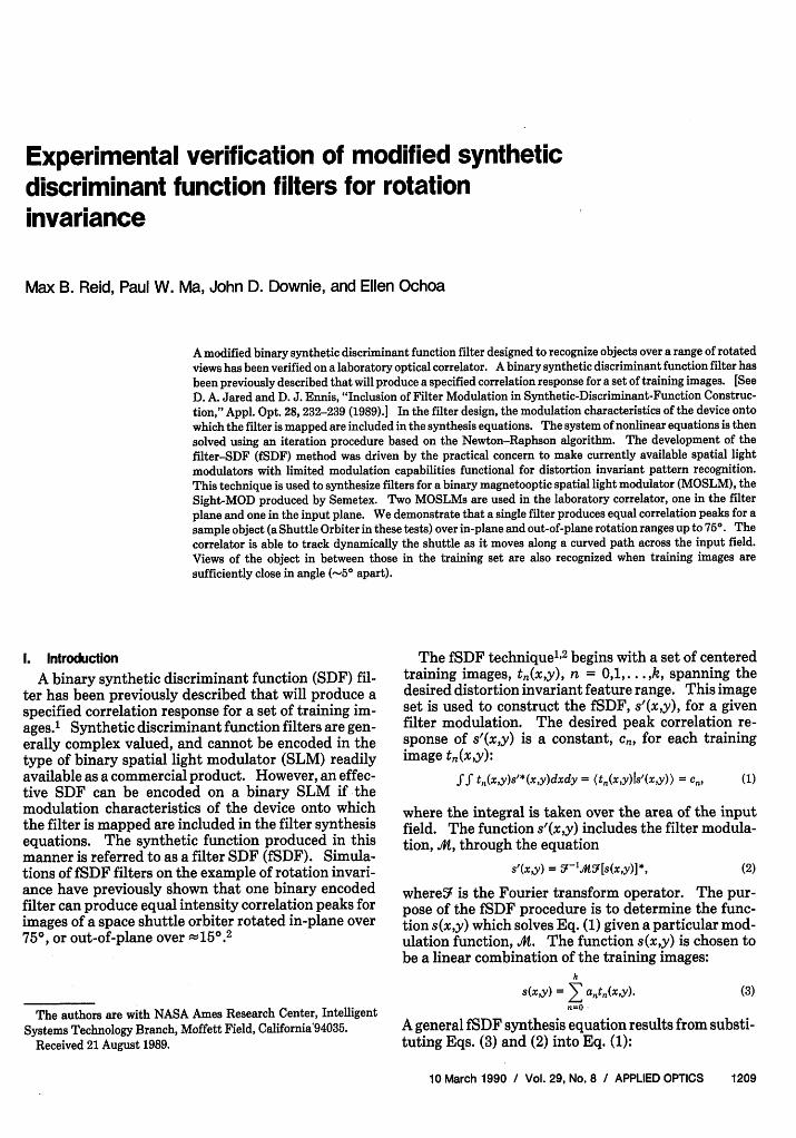
Fig. 4. Minimum peak and maximum clutter response vs in-planedistortion range. Peak data (closed squares) are the lowest respons-es measured at any 10 angle over the distortion range. Clutter data(open squares) are the highest responses over the distortion range.
declines with increasing distortion range, the averagePSR remains sufficiently greater than one to allow useof a threshold detector, even for a range of 900.
A more conservative evaluation of the rotation in-variance of an SDF is to consider the worst-case PSRacross the distortion range
PSRC = min' (8)max
where the critical PSR is found from the ratio of thelowest peak to the highest clutter value measured atany angle over the range. If PSRC > 1 for an fSDF,there will be no ambiguity in distinguishing peak fromclutter anywhere over the distortion range when asimple thresholder is used to evaluate the correlationresponse.
Figure 4 shows the minimum peak and maximumclutter measured at any angle within each distortionrange. The value of PSRC drops below 1 for a rangebetween 75 and 900. Therefore, one can conclude thata binary synthetic filter can be constructed by thismethod which is distortion invariant to in-plane rota-tions up to at least 75°. Both the general shapes of thecurves and the actual PSR and PSRC values seen inFigs. 3 and 4 agree very well with the results of fSDFsimulations.2
B. Out-of-Plane Rotations
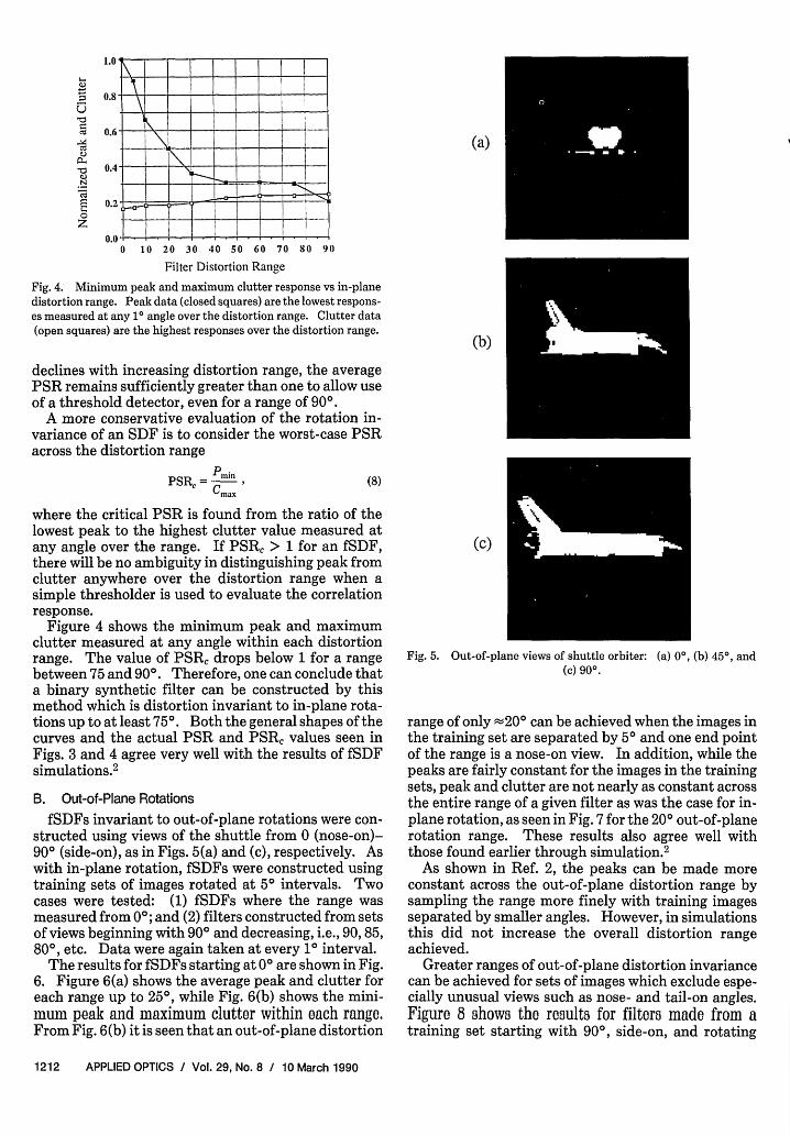
fSDFs invariant to out-of-plane rotations were con-structed using views of the shuttle from 0 (nose-on)-90° (side-on), as in Figs. 5(a) and (c), respectively. Aswith in-plane rotation, fSDFs were constructed usingtraining sets of images rotated at 50 intervals. Twocases were tested: (1) fSDFs where the range wasmeasured from 00; and (2) filters constructed from setsof views beginning with 90° and decreasing, i.e., 90,85,800, etc. Data were again taken at every 10 interval.
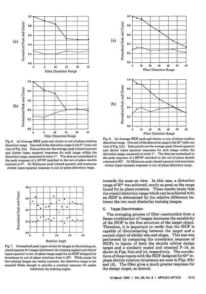
The results for fSDFs starting at 00 are shown in Fig.6. Figure 6(a) shows the average peak and clutter foreach range up to 250, while Fig. 6(b) shows the mini-mum peak and maximum clutter within each range.From Fig. 6(b) it is seen that an out-of-plane distortion
range of only -200 can be achieved when the images inthe training set are separated by 50 and one end pointof the range is a nose-on view. In addition, while thepeaks are fairly constant for the images in the trainingsets, peak and clutter are not nearly as constant acrossthe entire range of a given filter as was the case for in-plane rotation, as seen in Fig. 7 for the 200 out-of-planerotation range. These results also agree well withthose found earlier through simulation.2
As shown in Ref. 2, the peaks can be made moreconstant across the out-of-plane distortion range bysampling the range more finely with training imagesseparated by smaller angles. However, in simulationsthis did not increase the overall distortion rangeachieved.
Greater ranges of out-of-plane distortion invariancecan be achieved for sets of images which exclude espe-cially unusual views such as nose- and tail-on angles.Figure 8 shows the results for filters made from atraining set starting with 900, side-on, and rotating
Fig. 6. (a) Average fSDF peak and clutter vs out-of-plane rotationdistortion range. One end of the distortion range is the 00 (nose-on)view of Fig. 5(a). Data points are the average peak (closed squares)and clutter (open squares) responses for each image within thedistortion range, measured at every 10. The data are normalized tothe peak response of a BPOF matched to the out-of-plane shuttleoriented at 00. (b) Minimum peak (closed squares) and maximum
clutter (open squares) response vs out-of-plane distortion range.
-00
3uN
z
0.6
0.61 --- I---I n
0 5 10 15 2
Rotation Angle
Fig. 7. Normalized peak (open circles for images in the training set,closed squares for images inbetween the training angles) and clutter(open squares) vs out-of-plane image angle for an fSDF designed forinvariance to out-of-plane rotations from 0-20°. While peaks forthe training images are nearly constant, the distortion range is notsampled finely enough to provide a constant response for angles
inbetween the training angles.
0.8
0.6
0.4
0.2
0.0
(a) i-uN
z
0.8
0.6
0.4
0.2
0.0
4s I
| m- -~~~~~~~~~~~~~~~~~~~~~~-== w = = =~~N-
0 lo 20 30 40 so 6C
Filter Distortion Range
i___ I. _N __ _~ _ _ _ _-~~
0 10 20 30 40 50 60
Filter Distortion Range
Fig. 8. (a) Average fSDF peak and clutter vs out-of-plane rotationdistortion range. One end of the distortion range is the 90° (side-on)view of Fig. 5(b). Data points are the average peak (closed squares)and clutter (open squares) responses for each image within thedistortion range, measured at every 10. The data are normalized tothe peak response of a BPOF matched to the out-of-plane shuttleoriented at 900. (b) Minimum peak (closed squares) and maximum
clutter (open squares) response vs out-of-plane distortion range.
towards the nose-on view. In this case, a distortionrange of 600 was achieved, nearly as great as the rangefound for in-plane rotation. These results imply thatthe overall distortion range which can be achieved withan fSDF is determined by the relative difference be-tween the two most dissimilar training images.
C. Target Discrimination
The averaging process of filter construction from alinear combination of images decreases the sensitivityof the fSDF to the fine structure of the target object.Therefore, it is important to verify that the fSDF iscapable of discriminating between the target and asecond object of similar size and shape. This test wasperformed by comparing the correlation response offSDFs to inputs of both the shuttle orbiter designtarget and a similarly scaled and oriented F-18, asshown in Figs. 9(a) and (c), respectively. The correla-tions of these inputs with the fSDF designed for 600 in-plane shuttle rotation invariance are seen in Figs. 9(b)and (d). The filter gives a much greater response forthe design target, as desired.
Fig. 9. Correlation response of two images with an fSDF designedfor invariance to in-plane rotation of the shuttle orbiter over a rangeof 600. (a) shuttle orbiter, (b) correlator output using shuttle input,
(c) F/18, and (d) correlator output using F/18 input.
c)
.N
z
1.0 I
0.8-
0.6 \
0.4
0.2 - ,I II
0.0 - -0.0 = = = =0 15 30 45 60 75
Filter Distortion Range
Fig. 10. Correlation peak of F-18 and lowest correlation peak ofshuttle with fSDFs designed to recognize the shuttle over the givendistortion ranges. Shuttle peak correlation data (closed squares)are the lowest responses measured at any 10 angle over the distortionrange. The dashed line is a threshold for shuttle recognition. Thepeak correlation responses of an F/18 image with the given filters is
given by the closed circles.
In addition, it can be seen from Fig. 10 that theshuttle can be unambiguously identified at any anglewithin the design distortion range for ranges up to 750by using simple thresholding. The curve in the figure,
repeated from Fig. 4, gives the weakest peak correla-tion response of the shuttle at any orientation withinthe given distortion range. A constant threshold, giv-en by the dashed line in the figure, is sufficient to allowshuttle identification. Discrimination between theshuttle and another object is unimpaired as long as theobject's correlation response does not rise above thisthreshold. The data points for the F-18 in Fig. 10(closed circles) show its response when correlated withfSDFs of various shuttle-rotation distortion ranges.No evidence of discrimination ambiguity is seen: theF-18 will not be identified as a shuttle when using anyof the fSDFs.
V. Conclusions
These experiments confirm that effective binarySDFs can be constructed if the binary nature of thefilter modulation is included in SDF synthesis. It hasalso been demonstrated that the iterative procedureneeded to produce the SDF is well performed on theoptical correlator, as opposed to off-line computation.Binary synthetic discriminant filters have been dem-onstrated which produce approximately equal correla-tion peaks over in-plane rotation ranges up to 750 andout-of-plane rotation ranges up to 600. This tech-nique, along with the translational position invarianceof optical filters, allows a single filter to track theshuttle orbiter as it moves along a curved path acrossthe input field. Given the invariance of BPOFs to1800 rotations, sequencing through only three fSDFfilters, each invariant over a different 600 range, willallow identification of an object oriented in any in-plane rotation angle over 3600. Using ordinaryBPOFs which are not distortion invariant, this taskwould require on the order of 100 separate filters.These results demonstrate that practical, commercial-ly available spatial light modulators with limited mod-ulation capabilities can be used to implement distor-tion invariant pattern recognition.
References
1. D. A. Jared and D. J. Ennis, "Inclusion of Filter Modulation inSynthetic-Discriminant-Function Construction," Appl. Opt. 28,232-239 (1989).
2. D. A. Jared, "Distortion Range of Filter Synthetic DiscriminantFunction Binary Phase-Only Filters," Appl. Opt. 28, 4835-4839(1989).
3. D. Psaltis, E. G. Paek, and S. S. Venkatesh, "Optical ImageCorrelation with a Binary Spatial Light Modulator," Opt. Eng.23, 698-704 (1984).
4. D. F. Flannery, A. M. Biernacki, J. J. Loomis, and S. L. Cart-wright, "Real-Time Coherent Correlator Using Binary Magne-tooptic Spatial Light Modulators at Input and Fourier Planes,"Appl. Opt. 25, 466-466 (1986).
5. M. A. Flavin and J. L. Horner, "Amplitude Encoded Phase-OnlyFilters," Appl. Opt. 28, 1692-1696 (1989).