EXPERIMENTAL VERIFICATION OF MULTI-LEVEL DPFC WITH HARDWARE RESULTS B.Vijaya Krishna 1 ,B.Venkata Prashanth 2 , P.Sujatha 3 Assistant Professor 1 , Professor & Head 2 Professor 3 ,Department of EEE 1,2,3 , Bapatla Engineering College 1 , QIS CET, Ongole 2 , JNTUA Ananthapur 3 [email protected], [email protected], [email protected]July 23, 2018 Abstract According to increased demand in electricity and by enhancing many numbers of non-linear loads. There is a need to adopt some controlling devices in electrical power. In this article, power quality is improved using Multilevel Distributed power flow controller (DPFC) in distribution systems is developed. A DPFC is one of the contemporary FACTS devices and its structure is analogous to the UPFC. In DPFC, common DC-link capacitor which is placed between the series and shunt converters as in UPFC, is eliminated and the single 3-phase series converter is splitted into more number of 1-phase series converters in transmission system. It will enable the DPFC for controlling network parameters. DPFC will reduce the cost and will increase the consistency of the system. The MLIs are used for high voltage and high power applications. The HSLHBI will produce an output 1 International Journal of Pure and Applied Mathematics Volume 120 No. 6 2018, 9447-9473 ISSN: 1314-3395 (on-line version) url: http://www.acadpubl.eu/hub/ Special Issue http://www.acadpubl.eu/hub/ 9447
According to increased demand in electricity and byenhancing many numbers of non-linear loads. There is aneed to adopt some controlling devices in electrical power.In this article, power quality is improved using MultilevelDistributed power flow controller (DPFC) in distributionsystems is developed. A DPFC is one of the contemporaryFACTS devices and its structure is analogous to theUPFC. In DPFC, common DC-link capacitor which isplaced between the series and shunt converters as inUPFC, is eliminated and the single 3-phase seriesconverter is splitted into more number of 1-phase seriesconverters in transmission system. It will enable theDPFC for controlling network parameters. DPFC willreduce the cost and will increase the consistency of thesystem. The MLIs are used for high voltage and highpower applications. The HSLHBI will produce an output
1
International Journal of Pure and Applied MathematicsVolume 120 No. 6 2018, 9447-9473ISSN: 1314-3395 (on-line version)url: http://www.acadpubl.eu/hub/Special Issue http://www.acadpubl.eu/hub/
9447
in the the form of staircase waveform and this will be likesinusoidal waveform which will lead to the decrease ofHarmonics. The fuzzy logic controller (FLC),proportional-integral (PI) controller and multi-carriersinusoidal PWM technique are designed for DPFC tocontrolling its parameters. The performance of thedesigned DPFC for distribution system is verified byconstruing the MATLAB/Simulink model. The newresults are represented to show the presentation of thedesigned MDPFC system in a distribution network.Experimental setup of Multilevel DPFC is experimentallyverified with Load condition and without Load condition.Instead of Many series converters, here only single seriesconverter is used to reduce cost and improve betterperformance.
Index Terms: FACTS Devices, Power Quality, DPFC,Multi Level Inverters, Intelligent Controller.
1 INTRODUCTION
A fault in a power system network is almost impossible to avoidand it will cause power quality issue which is the major affair ofpower industries [1]. Main causes of power quality disturbancesare insulation failure, tree falling, birds contact, lightning or afault on an adjacent feeder [2]. The power quality disturbanceswill occur may be in the form of voltage sag, swells, voltageimbalances, transients, interruptions and harmonics, which canaffect the performance of electrical apparatus to the industries[3-4]. Out of these disturbances harmonics, voltage sags and swellsare the major problems, because which can cause themalfunctioning or tripping the equipment [5-6]. Anotherimportant Power Quality problem is the poor power factor to theincoming utilization. This is caused by the usage of inductionmotors, other nonlinear power electronic loads such as variablespeed AC drives [7] and thyristor rectifiers. These undesirablevoltage sags and poor power factor can be reduced by connectingthe controllable devices in parallel to the load [8]. A variety ofcustom power devices implemented for compensating powerquality problems in a distributed system [9-11].
2
International Journal of Pure and Applied Mathematics Special Issue
9448
Custom power devices are DSTATCOM, DVR and DPFC. ADVR is used in medium-to-low voltage levels to improve customerpower quality [12]. DSTATCOM is a shunt-connected FACTSdevice. It takes care about the power quality issues that occur dueto currents [15]. It comprises of a DC link capacitor, 3-phaseinverter (Thyristor, IGBT) module, a coupling transformer, ACfilter, control strategy [16-17]. Primary component of theD-STATCOM is voltage-source inverter which will convert DCinput voltage into a 3-phase output voltage at the fundamentalfrequency. Inverter circuit is most important component ofDSTATCOM and various inverter topologies are: cascadedH-bridge topology, neutral point clamped topology and flyingcapacitor topology [18]. Of all the topologies, cascaded H-bridgeinverters are commonly used due to the modularity and easiness[19]. Different modulation techniques are used for cascadedH-bridge inverters. Cascaded H-bridge inverters can also increaselevel of output voltage by more H-bridges. Fuzzy logic controller(FLC) for speed controller of induction motor drive through A.Cchopper has been reported [20]. From the article, the performanceof the motor parameter with FLC has well. SMC, PI controller,and SMC plus FLC for Luo-Converters has been presented[21-23]. Among these controllers, SMC plus PI controller hasperformed well for converters.
The DPFC is novel FACTS device, and its construction isanalogous to UPFC [13]. The key benefit of DPFC is eliminationof DC-link capacitor for 3rd-harmonic component [14]. From theabove pointed out problems are solved by designed hybrid 7-levelH-bridge inverter (HSLHBI) based DPFC in distribution systemwith FLC.
Therefore, in this article is to propose a HSLHBI based DPFC indistribution system with FLC. The presentation of the designed isconfirmed at different loads using MATLAB/Simulink softwareplatform.
3
International Journal of Pure and Applied Mathematics Special Issue
9449
2 DPFC PRINCIPLE AND
MODELLING
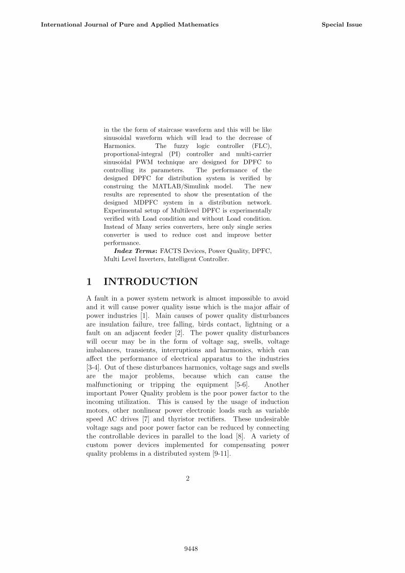
Figure 1. DPFC
Structure of DPFC is formed by the combination of severalindividual converters as shown in figure. Series converters arethose which are connected in series to the transmission linesystem. The purpose of this series converter is to injectcontrollable voltage in the transmission line system on thefundamental frequency which will leading to the controlling ofpower flow. Shunt converter is placed between the transmissionline, ground. The main function of the shunt converter issupplying the real power that is required to series converter forcompensation of the reactive power in grid.
The real power is substituted by the harmonics in the grid due tothe absence of DC link capacitor links shunt, series converters.Important source is the real power, is obtained by multiplying thecurrent and voltage which are the average values. But theseaverage voltages and currents are containing the fundamentalharmonics. But the cross product integrals of the terms forvarious frequencies is zero, the real power can be written
4
International Journal of Pure and Applied Mathematics Special Issue
9450
P =∑∞
n=1 VnIn cosψn........(1)
Here,ψn is the phase angle of current, voltage in the nth orderharmonic.
The above equation describes real power for different frequenciesis divided among themselves. Their voltages and currents in onefrequency have no effect on the other frequency components. Toexchange the real power in the DPFC, 3rd order harmoniccomponent is used it is for they are filtered easily by using a Y- DTransformers.
A. Steady State Analysis of DPFC
Figure 2. DPFC equivalent diagram in a two bus network.
In this, each converter is utilized for regulating the seriesimpedance of the voltage source converter which will generatevoltage values for different frequency. DPFC is placed in two bussystem with receiving end voltage Vr and sending end voltage Vs
respectively. In the network, L is representation of inductance,and I is the representation of Line current. Vse1 is the seriesconverter injected voltage at fundamental frequency, Vse3 is theinjected voltage of series converter for 3rd harmonic. Shunt
5
International Journal of Pure and Applied Mathematics Special Issue
9451
converter is coupled to the two bus power system network by asending end bus through inductor Lsh. Shunt converter willgenerate Vsh1, Vsh3 voltages. Ish is injected current by the shuntconverter. Pr is receiving end real power and Qr is the receivingend reactive power of the system.
Pr + jQr = Vr ∗ I∗1 = Vr
[Vs−Vr−Vse1
jX1
]∗......(2)
Here,X1 = ω1L is line impedance of the system at fundamentalfrequency.
Active power Pro and Reactive power Qro compensation of thesystem without DPFC can be represented by
Pro + jQro = Vr
[Vs−Vr
jX1
]∗......(3)
Similarly, the active and reactive power flow control limit rangesof the system by using FACTS device can be represented as
Prc + jQrc = VrV ∗se1
jX1....(4)
Here,
Qrc and Prc are reactive power and active power limit range.
Power flow control range of DPFC is directly proportional toseries converter peak voltage for certain conditions of fixed valuesof line impedance and receiving end voltage. V∗se1 is rotated360◦for regulating the transfer of complex and real powers intransmission line by using the eqs (2) & (3). DPFC control abilitycan be written as
(Pr − Pro)2 + j(Qr −Qro)
2 =[V |Vse1|
X1
]2....(5)
6
International Journal of Pure and Applied Mathematics Special Issue
9452
Figure 3. power control range of real power, reactive power inDPFC using transmission angel.
DPFC is represented in the form of a circle in PQ complex planewith the control range is presented in above diagram. The figureshows the power flow control locus without DPFC. Thecompensation of active and reactive powers (Pro , Qro) representscircle of radius |V 2|/|X1| and with midpoint is denoted by thecoordinates of active power, P=0 and reactive power,Q=|V 2|/|X1|. Each point on the circle refers Qro and Pro rangesat power angle θ for a non-regulated transmission line system. Byrotating Vse1 at peak amplitudes, the possible boundaries for theregions of Pr and Qr are arrived as shown in above figure. Vse1 atthe fundamental frequency can be written as
Vsel = (Sr−Sro)jX1
Vr....(6)
Here,Sr real power of regulated systemSro reactive power of non-regulated system.
In a 360◦rotatable path, the injected voltage is a real and thecomplex powers are provided for series converter. Although thecomplex power is nearly represented for series converter andnecessary real power will be provided by the shunt converter for3rd harmonic. This power can be represented as
7
International Journal of Pure and Applied Mathematics Special Issue
9453
Pse1 = X1
|Vr|2 |Sr||Sro| sin(ψro − ψr)....(7)
Here,ψro represents power angle of system without DPFC at receivingend.ψr represents power angle of system with DPFC at receiving end.
3 CONTROL METHODOLOGY FOR
MDPFC
Figure 4. MDPFC- block diagram
Multilevel DPFC is connected in a transmission line system forpower quality improvement. It consists of a series converter and ashunt converter. Both the converters are connected to multilevelinverters along with DC Link capacitors. A Central controlSystem is used for controlling puspose. High pass filter isassociated at terminal end of transmission line system. Themultilevel Inverters used in MDPFC are a 5 switch 7-level Multilevel inverters.
8
International Journal of Pure and Applied Mathematics Special Issue
9454
A. Central controller pulse driver Circuit
Figure 5. Central Control Pulse diagram for both series & shuntconverter
Control pulse diagram for series converter is presented in abovefigure. This series converter uses 555 IC timer for the pulsegeneration and it is also used as oscillator, a flip-flop element.Astable mode of 555 IC timer is operated as electronic oscillator.Its applications are, it is used as an LED, as a Lamp Flashers, forPulse Generation, in Logic Clocks, for Tone Generation, inSecurity Alarms, for Pulse Position Modulation etc. 555 Timercan also be used as ADC, for converting analog value to pulselength.
9
International Journal of Pure and Applied Mathematics Special Issue
9455
B. Shunt and series controller pulse diagram
Figure 6. Control Pulse diagram for shunt converter
Control Pulse diagram for Shunt and series converter is shown inabove figure. For pulse generation,Shunt and series converter usesa AD633 and a 3524 Microcontroller.
A AD633 is multiplier with low cost. It comprises of a trans-linearcore and a reference Zener. X, Y are the differential inputs arechanged into differential currents by using the voltage to currentconverters. A unity-gain output amplifier is connected to asumming point. product of the currents will be obtained bymultiplying the core. Reference Zener will provide 10 V ScaleFactor. Z is summing node of amplifier that will allow the user foradding two or more multiplier outputs, and will convert theoutput voltage into current. It will also perform various analogcomputational functions.
10
International Journal of Pure and Applied Mathematics Special Issue
9456
An IC 3524 is a chip of fixed frequency PWM voltage regulatorwith a control circuit. It consists of different outputs for a singleended and for pull-push operations. The SG3524 IC has all thefunctions that are necessary to produce a regulating power supplyor an electrical inverter or a switching regulator within a singleIC. It can also be used as a control element for high power outputapplications. PWM is a method for adjusting the pulse width in apulse group in co ordinance with the control signal. If the controlvoltage is high, then the width of the resultant pulses willincrease. Also by using a sinusoidal frequency control voltage forthe pulse width modulation circuits, it will generate a high powerwaveform and whose average voltage will vary with the sine waveand is also suitable for the driving of AC loads.
4 HYBRID SEVEN LEVEL
H-BRIDGE INVERTER
Figure 7. Circuit diagram of Hybrid 7-Level H- Bridge Inverter.
11
International Journal of Pure and Applied Mathematics Special Issue
9457
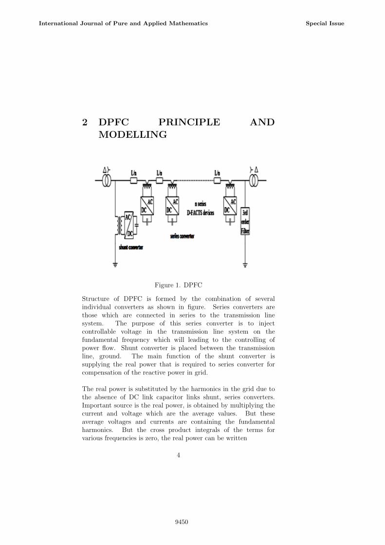
Table 1. Switching Pattern between a and b of inverters
Generally, the voltage jamming ability of the high speed switchingdevices like IGBT and IGCT are controlled with the modularH-bridge topologies [16]. Apprehension of MLIs with a hybridmethod involves IGBT, IGCT operating in synchronization isachievable. Hybrid MLI topologies are required for high powerusages [17-18]. The topology addressed in [18] combines a GTObased inverter with an IGBT inverter, similar to the figure 1. It isvalidated with the combination of 300V and 100V DC busvoltages. It is possible to produce stepped waveforms by sevenlevel voltages like -400V, -300V, -100V, 0, 100V, 300V, 400V atevery phase leg output of the designed MLI.
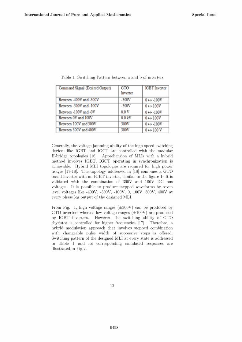
From Fig. 1, high voltage ranges (±300V) can be produced byGTO inverters whereas low voltage ranges (±100V) are producedby IGBT inverters. However, the switching ability of GTOthyristor is controlled for higher frequencies [17]. Therefore, ahybrid modulation approach that involves stepped combinationwith changeable pulse width of successive steps is offered.Switching pattern of the designed MLI at every state is addressedin Table 1 and its corresponding simulated responses areillustrated in Fig.2.
12
International Journal of Pure and Applied Mathematics Special Issue
In this part FLC based DPFC with HSLHBI or VSC is discussed.The main aim of DPFC is to increase the transmission line powerquality in the power system. The MATLAB/Simulink model ofthe designed system is shown in Fig. 5.
The simulation diagram represented consists of three sub-sytemsfor three individual phases which consists of pulse generationcircuit diagram. The shunt and series converters are also shownwhich are interconnected to the pulse generation circuit of thesubsystems. At the end of the system three loads are consideredto verify the output voltage values for different switching intervals.
13
International Journal of Pure and Applied Mathematics Special Issue
9459
Figure 9. MATLAB/Simulink model of FLC based DPFC fordistribution system.
Figure 10. Performance of the FLC based seven level VSC DPFCfor power system, Source voltage and current.
The simulated load voltages, currents, real power, reactive powereffects of designed power system without DPFC. It is evident thatthe designed power system without DPFC has contains moreharmonics in the its load voltages and currents, 20kW real power,4kW reactive power for power system without DPFC. Fig. 7 showthe simulated performance parameters of HSLHBI DPFC for
14
International Journal of Pure and Applied Mathematics Special Issue
9460
power system using classical PI controller. From these results, itis clearly found that designed system with PI controller hasproduced good performance such as source current THD of 3.31%,ripple of D.C link capacitor voltage ML VSC of 0.0001V, goodvoltage regulation, source current and voltage should be in phaseand seven level output of VSC without voltage stress.
The simulated performance factors of seven level VSC DPFC forpower system with FLC. It shows the designed system with FLChas maked good performance such as source current THD of 3.1%,ripple of D.C link capacitor voltage ML VSC of 0.00001V,profcient voltage regulation, source current and voltage should bein phase and no voltage stress of seven level output of VSC.
The simulated performance parameters of power system in threephas faulty conditons with/without designed DPFC model. It isclearly obtained that the power system with designed DPFC hasperformed well during the three phas fault conditon.
6 EXPERIMENTAL HARDWARE
RESULTS
Figure 11. Experimental setup of MDPFC
15
International Journal of Pure and Applied Mathematics Special Issue
9461
Figure 12. Power diagram
This figure is the experimental representation of multilevelinverter with dpfc. Hybrid 7-Level H-bridge multilevel inverter isused in MDFC. In this experiment, we are using single shuntconverter and single series converter. Shunt converter is connectedin the line by using a 230/50V 3A transformer and the seriesconverter is connected in the line by using a 7V-5A/10V-3Atransformer. It reduces the cost of the system. Also by using itthe performance gets better when compared to many seriesconverters. This multilevel DPFC system produces an outputcorresponding to Multilevel inverter and the Output voltages ofswitching positions are shown below.
The Multilevel inverter uses only 5 switches for producing 7 levelvoltage output. Multilevel inverter used is a Hybrid 7-LevelH-bridge MLI. At the end of the system three loads areconnected. By switching between these three loads, the outputvoltage of the system is verified. Three different loads used are100 Ohms, 500 Ohms and 2K Ohms.
16
International Journal of Pure and Applied Mathematics Special Issue
9462
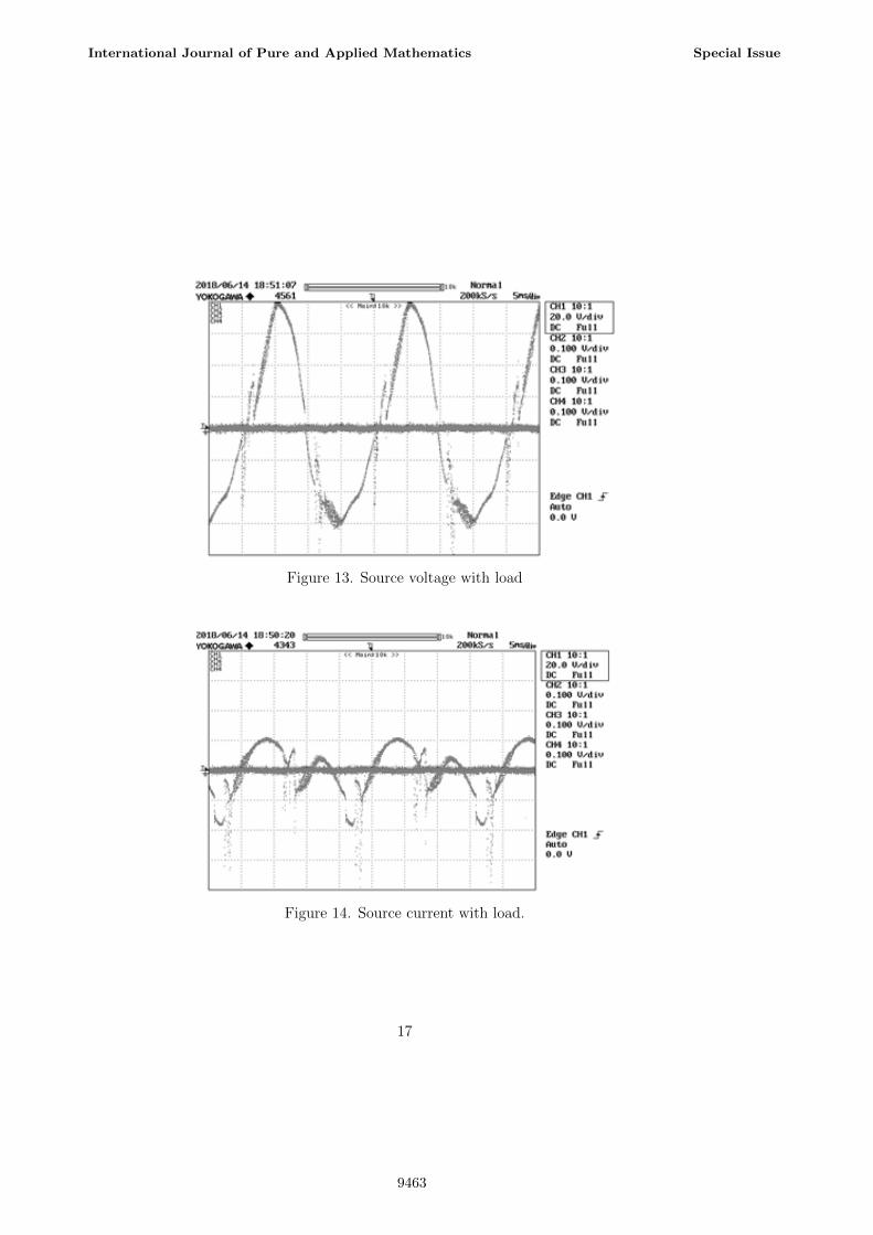
Figure 13. Source voltage with load
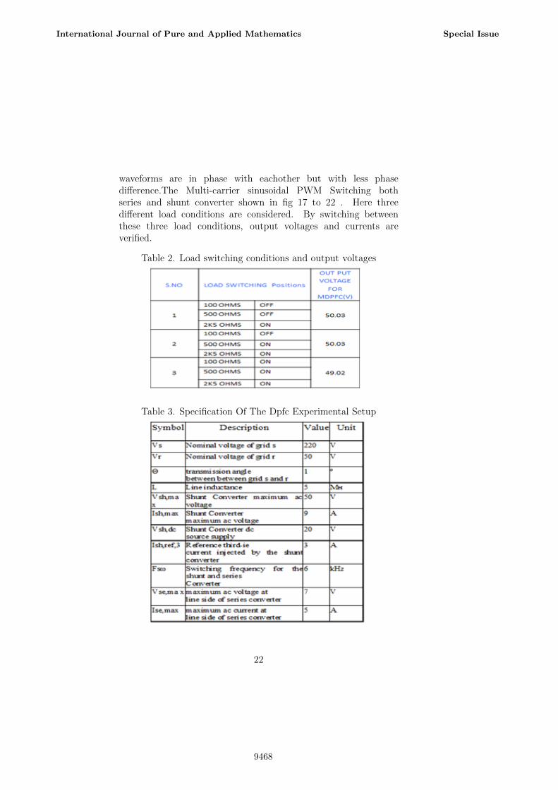
Figure 14. Source current with load.
17
International Journal of Pure and Applied Mathematics Special Issue
This figure no 1314shows how the source voltage and sourcecurrent are related to eachother. Voltage and Current are in phasebut there is a lot of phase shifting exists between them. Thisoccurs due to the presence of DPFC in the system and also due tomore number of series converters. Inorder to reduce this differencebetween voltage and current Multilevel DPFC uses only singleseries converter. In MDPFC the output voltage and current
21
International Journal of Pure and Applied Mathematics Special Issue
9467
waveforms are in phase with eachother but with less phasedifference.The Multi-carrier sinusoidal PWM Switching bothseries and shunt converter shown in fig 17 to 22 . Here threedifferent load conditions are considered. By switching betweenthese three load conditions, output voltages and currents areverified.
Table 2. Load switching conditions and output voltages
Table 3. Specification Of The Dpfc Experimental Setup
22
International Journal of Pure and Applied Mathematics Special Issue
9468
7 CONCLUSION
In this article Multilevel DPFC is used in distribution networkwas designed in MATLAB/Simulink software platform, also inhardware. The designed MDPFC has proficiently regulated theactive power and reactive power flow in the power system. Here,the series converter in DPFC uses the D-FACTS model, and ituses more number of converters on behalf of a single converter.And also one series converter instead of many series converterswill reduces cost and also reduces switching losses. It alsoimproves the performance and also reliability of DPFC isincreased due to decrease in the number of series converters. Thetotal cost of the MDPFC is also very less when compared to theUPFC. Hence, high-voltage isolation is not needed for the seriesconverters and the rating of components is very less. This resultwill demonstrate the improvement in the power quality throughdesigned seven level VSC DPFC.
References
[1] K Chandrasekaran, P A Vengkatachalam, Mohd Noh Karsitiand K S Rama Rao, Mitigation of Power Quality Disturbances,Journal of Theoretical and Applied Information Technology,Vol.8, No.2, pp.105-116, 2009.
[2] Priyanka Chhabra, Study of Different Methods for EnhancingPower Quality Problems, International Journal of CurrentEngineering and Technology, Vol.3, No.2, pp.403-410, 2013.
[3] Bindeshwar Singh, Indresh Yadav and Dilip Kumar,Mitigation of Power Quality Problems Using FACTSControllers in an Integrated Power System Environment: AComprehensive Survey, International Journal of ComputerScience and Artificial Intelligence, Vol.1, No.1, pp.1-12, 2011.
[4] J Ganesh Prasad Reddy and K Ramesh Reddy, PowerQuality Improvement Using Neural Network Controller BasedCascaded H-Bridge Multilevel Inverter Type D-STATCOM,International Conference on Computer Communication andInformatics, 2012.
23
International Journal of Pure and Applied Mathematics Special Issue
9469
[5] Lin Xu and Yang Han, Effective Controller Design forthe Cascaded H-bridge Multilevel DSTATCOM for ReactiveCompensation in Distribution Utilities, ElektrotehniskiVestnik, Vol.78, No.4, pp.229-235, 2011.
[6] Subhro Paul,SujaySarkar, SurojitSarkar, Pradip Kumar Sahaand Gautam Kumar Panda, By Dynamic Voltage Restorerfor Power Quality Improvement, International Journal ofEngineering And Computer Science, Vol.2, No.1, pp.234-239,2013.
[7] Aarti Rai, Enhancement of Voltage Stability & reactivePower Control of Distribution System Using Facts Devices,International Journal of Scientific Research Engineering &Technology, Vol.1, No.9, pp.1-5, 2012.
[8] S Suresh, N Devarajan, M Geetha and V Rajasekaran ,Investigation on D-STATCOM Operation for Power QualityImprovement in a Three Phase Three Wire DistributionSystem with a New Control Strategy, Control Theory andInformatics, Vol.1, No.2, 2011.
[9] D Mohan Reddy and T Gowrimanohar, Cascaded MultilevelInverter Based DSTATCOM for Restructured Power Systemsto Compensate the Reactive Power and Harmonics Using ShiftCarrier Techniques, IOSR Journal of Electrical and ElectronicsEngineering, Vol.4, No.3, pp.39-48, 2013.
[10] Shailesh M Deshmukh and Bharti Dewani, Overviewof Dynamic Voltage Restorer (DVR) for Power QualityImprovement, International Journal of Engineering Researchand Applications, Vol.2, No.6, pp.1372-1377, 2012.
[11] A Boudaghi and B Tousi, DSTATCOM Based Five-LevelCascade H-Bridge Multilevel Inverter for Power QualityImprovement, International Journal on Technical and PhysicalProblems of Engineering, Vol.4, No.3, pp.110-117, 2012.
[12] Veeraiah Kumbha and N Sumathi, Power quality improvementof Distribution lines using DSTATCOM under various loadingconditions, International Journal of Modern EngineeringResearch, Vol.2, No.5, pp-3451-3457, 2012.
24
International Journal of Pure and Applied Mathematics Special Issue
9470
[13] Kiran Kumar Pinapatruni and Krishna Mohan, DQ basedControl of DSTATCOM for Power Quality Improvement,International Journal of Electrical, Electronics andCommunication Engineering, Vol.2, No.5, pp.207-227,2012.
[14] Tapajit Ghosh, The Role of DSTATCOM for Power QualityImprovement In Distribution Networks, International Journalof Engineering Research and Applications, Vol.2, No.3,pp.3218-3222, 2012.
[15] Mehdi Hosseini, Heidar Ali Shayanfar and Mahmoud Fotuhi-Firuzabad, Modeling of Static Series Voltage Regulator(SSVR) in Distribution Systems for Voltage Improvement andLoss Reduction, Leonardo Electronic Journal of Practices andTechnologies, pp.61-82, 2008.
[16] P. K. Steimer, H.E. Gruning, J. Wuninger, E. Caroll, S.Klaka,S. Linder,;A New Emerging Technology for High Power, LowCost Inverters, IEEE-IAS98 Conference Proceedings, pp.1592-1599, 1998.
[17] H. Gruning, Power Electronics Circuit Arrangement havingPlural Power Converters, U.S. Patent No. 5,805,487, 1998.
[18] M.D. Manjrekar, T.A. Lipo A Hybrid Mulilevel InvertersTopology for Drive Applications, IEEEAPEC98 ConfernceProceedings, pp. 523-529, 1998
[19] V. Agelidis, M. Calais,;Application specific harmonicperformance evaluation of multicarrier PWM techniques,IEEE-PESC98 Conference Record, pp. 172-178, 1998.
[20] J. Gayathri Monicka, Dr. N.O.Guna Sekhar, K. RamashKumar, Performance Evaluation of Membership Functionson Fuzzy Logic Controlled AC Voltage Controller for SpeedControl of Induction Motor Drive, International Journal ofComputer Applications, ISSN (0975 8887) Volume 13 No.5,January 2011.
[21] B.Vijayakrishna, B.Venkataprasanth ,P.SujthaMATLAB/simulink study of multi-level inverter topologies
25
International Journal of Pure and Applied Mathematics Special Issue
9471
using minimized quantity of switches, International Journalof Engineering Technology, 7 (1.5) (2018) 209-216
[22] B.Vijaya Krishna, B.Venkata Prashanth , K.S.R.AnjaneyuluDesigning of Multilevel DPFC to Improve Power QualityInternational Conference on Electrical, Electronics, andOptimization Techniques (ICEEOT) - 2016 ,978-1-4673-9939-5/16/$31.00 2016 IEEE
[23] K.Ramash Kumar, S. Jeevananthan, S. RamamurthyImproved Performance of the Positive Output ElementarySplit Inductor-Type Boost Converter using SlidingMode Controller plus Fuzzy Logic Controller, WSEASTRANSACTIONS on SYSTEMS and CONTROL, Volume 9,2014, pp. 215-228.
26
International Journal of Pure and Applied Mathematics Special Issue


![Deciding optimal location for placing FACTS devices [UPFC, IPQC, DPFC] using Bang-Bang control technique](https://static.documents.pub/doc/80x56/577cc8811a28aba711a300aa/deciding-optimal-location-for-placing-facts-devices-upfc-ipqc-dpfc-using.jpg)


