14 Experiments of In-Vehicle Power Line Communications Fabienne Nouvel 1 , Philippe Tanguy 1 , S. Pillement 2 and H.M. Pham 2 1 Laboratory IETR Rennes, 2 University of Rennes 1, Irisa Labs, France 1. Introduction The omnipresence of ECU (electronic control units) in vehicles has lead the automotive industry to face a great challenge in its transition from mechanical engineering towards mechatronical products. The X-by-wire and X-tainment applications involve efficient networks that allow bus sharing while reducing both cabling costs, number of wires and connectors. This chapter deals with the embedded in-vehicle networks and the use of emerging technologies combining different communication systems like power line communications (PLC) and/or wireless communications and pushing to a dynamic configuration of both networks and ECU. The ECUs that replace mechanical or hydraulic systems require secure and specific bus for communication. In order to exchange information between sensors and actuators, different networks have been proposed, from low data rate up to high data rate namely LIN, CAN, FlexRay. In section 2, these networks are presented identifying their strengths and possible drawbacks. As a result of using these fieldbuses, the cost of advanced systems should plummet. Furthermore, X-by-wire systems do not depend on conventional mechanical or hydraulic mechanisms. In (Len & Hefferman, 2001), the authors demonstrate the advantages of X-by-wire and embedded networks. Considering these specific domain embedded networks, we can observe that each solution uses its specific wires and communication system. The growth of the complexity leads to the necessity to commit to a limited set of networks which answers to these multiple applications. An attractive solution to reduce the wires is the power line communication (PLC) using the power lines (12/42V) to transmit both the power and the messages without functional barriers domain. It can answer the vehicles requirements namely cost, decrease of the amount of wires, flexibility and bandwidth. Section 3 is dedicated to PLC systems. Nowadays, this technique is already proposed for domestic uses (Ribeiro et al., 2006). In vehicle PLC seems to be a promising technology and has numerous advantages; it could reduce the weight of wires, the amount of splicing, and simplify cables bundle and the networks between ECU. The background and current studies are first addressed in Section 3. Although high data rate and flexibility obtained for indoor domestic PLC are proven, it is not possible to apply them directly to cars because the geometrical characteristics and wires www.intechopen.com
Transcript
14
Experiments of In-Vehicle Power Line Communications
Fabienne Nouvel1, Philippe Tanguy1, S. Pillement2 and H.M. Pham2 1Laboratory IETR Rennes,
2University of Rennes 1, Irisa Labs, France
1. Introduction
The omnipresence of ECU (electronic control units) in vehicles has lead the automotive
industry to face a great challenge in its transition from mechanical engineering towards
mechatronical products. The X-by-wire and X-tainment applications involve efficient
networks that allow bus sharing while reducing both cabling costs, number of wires and
connectors.
This chapter deals with the embedded in-vehicle networks and the use of emerging
technologies combining different communication systems like power line communications
(PLC) and/or wireless communications and pushing to a dynamic configuration of both
networks and ECU.
The ECUs that replace mechanical or hydraulic systems require secure and specific bus for
communication. In order to exchange information between sensors and actuators, different
networks have been proposed, from low data rate up to high data rate namely LIN, CAN,
FlexRay. In section 2, these networks are presented identifying their strengths and possible
drawbacks. As a result of using these fieldbuses, the cost of advanced systems should
plummet. Furthermore, X-by-wire systems do not depend on conventional mechanical or
hydraulic mechanisms. In (Len & Hefferman, 2001), the authors demonstrate the advantages
of X-by-wire and embedded networks.
Considering these specific domain embedded networks, we can observe that each solution
uses its specific wires and communication system. The growth of the complexity leads to the
necessity to commit to a limited set of networks which answers to these multiple
applications. An attractive solution to reduce the wires is the power line communication
(PLC) using the power lines (12/42V) to transmit both the power and the messages without
functional barriers domain. It can answer the vehicles requirements namely cost, decrease of
the amount of wires, flexibility and bandwidth. Section 3 is dedicated to PLC systems.
Nowadays, this technique is already proposed for domestic uses (Ribeiro et al., 2006). In
vehicle PLC seems to be a promising technology and has numerous advantages; it could
reduce the weight of wires, the amount of splicing, and simplify cables bundle and the
networks between ECU. The background and current studies are first addressed in Section
3. Although high data rate and flexibility obtained for indoor domestic PLC are proven, it is
not possible to apply them directly to cars because the geometrical characteristics and wires
www.intechopen.com
Advances in Vehicular Networking Technologies
256
topologies are totally different. Moreover, the in-vehicle PLC channels are affected by the
variable activation schedules of electrical functions, such as brakes, indicators, etc, which
produce sharp modifications in the circuit's load impedances over brief time intervals, as
presented in (Lienard et al., 2008). To optimize high bit-rate communication, the PLC
channel transfer function must be carefully studied because it is frequency selective.
Previous studies show that the promising techniques are based on wide bandwidth
transmission, such a spread spectrum or orthogonal frequency division multiplex (OFDM).
Section 4 provides a description of the experimentations using the existing DC electrical
wires. The discussion is framed by describing in particular the area of PLC applications.
Results for different cars configurations are presented and demonstrate the feasibility of
PLC for automotive.
Section 5 will complete the chapter by describing other alternative solutions for in-vehicle
communication based on wireless communications such as ZigBee, Wireless USB, Wifi ….
These technologies have been adopted for V2V, R2V and can be extended to in-vehicle
communication. Different solutions are proposed, giving a new perspective for ECU
communications, both for cars to cars and/or intra-cars communications.
In order to propose more flexibility with these different communication networks, new
electronic architecture need to be adopted to reduce the size of ECU. One solution is based
on dynamic reconfiguration. Section 6 will analyze this new concept for our embedded
system. Reconfigurable systems are already proposed for video driver assistance (Claus &
Stechele, 2010). The reconfiguration can increase both safety and flexibility. An ECU can
migrate tasks from one node to another. Furthermore, this functionality can be extended to
network architecture: according to the channel, the ECU loads, the modem can be
dynamically reconfigured to offer seamless communication between ECUs.
2. In-vehicle networks: overview of embedded solutions
Various vehicle buses for different tasks of communications between ECU are used today
according to their area of application (Navet, 2008). These embedded networks have both
increased the functionality and decreased the amount of wires. However, the usage of
different wires for the different networks still has the disadvantage of heavy, complex and
expensive. Among these networks, three of them are prevailing:
- the local interconnect network (LIN, the lowest data rate) : proposed by manufacturers,
the local interconnect network is used in on-off devices such as car seats, door locks,
rain sensors, …..
- the control area network (CAN, medium data rate) developed by BOSCH, is currently
the most widely used vehicular network. A typical vehicle can contain two or three
separate CAN networks operating at different transmission rates, from 125 Kbps up to a
higher-speed at 1 Mbps for more real-time-critical functions.
- the FlexRay is proposed for X-by-Wire applications which require higher data rate(10
Mbps) and safety. FlexRay is a fault-tolerant protocol designed for high-data-rate,
advanced-control applications. X-by-wire systems replace the mechanical control
systems with electronic component.
Figure 1 illustrates the embedded network architecture. We can observe that these networks
have a hierarchical structure.
www.intechopen.com
Experiments of In-Vehicle Power Line Communications
2.1 The Local Interconnect Network: LIN Conceived in 1998, the LIN network (LIN, 2003) is an inexpensive slow and serial bus used for distributed body control electronic systems in vehicle. It enables effective communication for sensors and actuators where bandwidth, speed and versality are not required (i.e. inside mechatronic based subsystems generally made of an ECU and its set of sensors and actuators). LIN is commonly used as a sub bus for CAN and FlexRay. A LIN network is based on one master node and LIN slaves (up to 16 over 40 meters line length). The master node decides when and which frame shall be transmitted according to the schedule table containing the transmission order. At the moment a frame is scheduled for transmission, the master sends the header inviting a slave node to send its data in response. Any node interested can read a data frame transmitted on the bus. The reliability of LIN is high but it does not have to meet the same levels as CAN. The LIN can be implemented using just a single wire, while CAN needs two. The physical layer (PHY) supports a data rate equal to 20 Kbps (due to electromagnetic limitations) but other transmission supports enabling higher data rates are possible. LIN is widely used in middle range cars but it can not support high data rate as required by devices like portable DVD players or multimedia applications.
2.2 The Control Area Network: CAN The CAN (CAN, 2009) is a widely communication fieldbus used in automotive and other real time applications. It is a serial communications protocol which efficiently supports distributed realtime control with a middle level of security. In automotive ECUs, sensors, anti-skid-systems, etc. are connected using CAN with bit rates up to 1 Mbps. However, in today’s car, CAN is used as an SAE (Society of Automotive Engineers) class C (classification defined in J2056/2 Survey, 1994)) network for real time control in the powertrain and
www.intechopen.com
Advances in Vehicular Networking Technologies
258
chassis domains (at 250 or 500 kbps). It is also implemented as an SAE class B network for the electronics in the body domain (at 125 kbps). In CAN, data are transmitted in frames containing up to 8 bytes of data and a number of control bits. A CAN frame is labelled by an identifier whose numerical value determines the frame priority. Depending on the CAN format (standard CAN 2.0A or extended CAN 2.0B) the size of the identifier is 11 bits (CAN 2.0A) or 29-bits (CAN 2.0B). Between CAN frames sent on the bus, there is also a 3 bit inter-frame space. The standard CAN frame format is depicted in Figure 2.
Fig. 2. The CAN frame (from (Nolte, 2006))
Regarding the CAN MAC layer, CAN is a collision-avoidance broadcast bus (CSMA/CA for carrier sense multiple access with collision avoidance), which uses deterministic collision resolution to control access to the bus. It implements a fixed-priority based arbitration mechanism that can provide real time guarantees and that is amenable to timing analysis. As distributed real time systems become more and more complex, the computing power is steadily growing, and the number of ECUs attached to CAN buses is growing. Thus CAN’s maximum speed of 1 Mbps can lead to performance bottlenecks. Hence, methods for increasing the achievable utilisation are needed, e.g., novel analysis methods that allow increased utilisation while guaranteeing timing requirements to be fulfilled, and novel approaches to schedule CAN.
2.3 The FlexRay protocol X-by-wire systems need fault-tolerant communications with predictable message transmissions and low jitter. This is traditionally solved using TDMA technologies, thanks to their predictable nature. FlexRay (FlexRay Consortium, 2009) is a TDMA communication system developed by a consortium founded in 2000, including both car and semiconductors manufacturers. FlexRay is a fault-tolerant protocol designed for high-data-rate, advanced-control applications. FlexRay is considered by manufacturers as the backbone network for the other networks like CAN or LIN Currently, FlexRay can handle communications at 10 Mbps. An overview of the FlexRay frame format is given in Figure 3. The frame consists of three segments: the header segment, the payload segment (up to 254 bytes of data), and the trailer or CRC segment. Communication is done in a communication cycle consisting of a static part and a dynamic part, where each of the parts may be empty. The sending slots are represented through the identifier (ID) numbers that are the same on both channels. The sending slots are used deterministically (pre-defined TDMA strategy) in the static part. In the dynamic part there can be differences in the phase on the two channels. Nodes that are connected to both channels send their frames in the static part simultaneously on both channels. An interesting feature of FlexRay is that it can provide scalable dependability i.e., the “ability to operate in configurations that provide various degrees of fault tolerance.”.
www.intechopen.com
Experiments of In-Vehicle Power Line Communications
However, this network still uses specific wires, which do not achieve compatibility with
other networks. So, gateways are necessary to transfer information from ECUs connected to
a domain network to ECUs connected to other networks. Those gateways could introduce
latency, errors, bottlenecks, and so on.
Other fault-tolerant networks have been developed, namely TTP and TT-CAN, but it seems
they are not the best choice for automotive manufacturers due to limited flexibility, high
costs and conflicting interests (Nolte, 2006).
Considering these specific embedded networks, we can observe that each solution uses its
specific wires and communication system. We can see the wide diversity of the solutions
and the necessity to find a limited set of networks which answers to the growing of the
multiple applications and requirements. Furthermore, gateways are necessary to switch
from one network to another one. This increases the propagation time and does not
guarantee real time. One idea to avoid the growth of wires would be to use the PLC
technology that is currently developed for indoor AC networks to transmit information over
the 12V power distribution (Rubin, 2002). The possible applications of automotive PLC are
very wide, extending from low-speed data buses for activating actuators to high-speed
multimedia applications.
3. Power Line Communication (PLC)
Many studies are carried out on in-vehicle PLC and focus both on channels, impulsive noises, drivers and protocols. The in-vehicle networks have reduced the number of wires, allowing communication between different typologies of electronic systems (safety devices, entertainment devices, and power train electronics). Additional cost reduction can be accomplished by adopting PLC approach. PLC can be considered to provide the physical layer for serial communications among ECU using for example LIN or CAN transceivers. In this case, the dedicated bus is eliminated. However, PLC can provide both the physical and MAC layers, allowing full compatibility between any ECU. This section considers first the different indoor PLC solutions. Then we focus of in-vehicle PLC driver solutions.
3.1 Indoor PLC In 2000, a coalition of manufacturers has established a new protocol HomePlug 1.0 that enables the establishment of an Ethernet-IP class network over power line channels (Home Plug V1.0, 2009). The HomePlug process is based on an OFDM technique (Bahai et al., 2004) whose major advantage for the embedded PLC application is to cope with the frequency
www.intechopen.com
Advances in Vehicular Networking Technologies
260
selectivity of the power line channel caused by the multiple reflections of the loads connected to the power grid and by the coupling to the other cables placed in the same bundle. The modulation is based on 128 subcarriers equally spaced from 4.3 MHz to 25 MHz, in conjunction coding applied before differential encoding. HomePlug uses CSMA/CA protocol to access to the network. Figure 4 represents the PHY frame format.
Fig. 4. HomePlug V1.0 PHY frame format (from (HomePlug, 2009))
Table 1. PHY and MAC layers of current PLC solutions (from (OMEGA, 2008))
More recently, the HomePlug AV (HPAV) has been introduced and will be the second major
standard released by the HomePlug Powerline Alliance (Gavette, 2006) (Afkhamie et al.,
www.intechopen.com
Experiments of In-Vehicle Power Line Communications
261
2005). The main HomePlug AV’s objective is to distribute multi-media content within the
house as well as data. The PHY layer still operates in the frequency range of [2 – 28] MHz
and provides a 200 Mbps PHY channel rate (150 Mbps net information rate).
Long OFDM symbols with 917 usable carriers (tones) are used in conjunction with a flexible
guard interval. Modulation densities from BPSK) to 1024 QPSK are independently applied
to each carrier based on the channel characteristics between the transmitter and the receiver.
Experimental systems of HPAV have been field tested in houses, suggesting that on average
HomePlug AV system achieves 10 times the data rate of a HomePlug 1.0 system.
At the same time, The HD-PLC (High Definition Power Line Communication) (Galli, 2008)
solution has been proposed by Panasonic. It is based on a specific OFDM modulation called
Wavelet-OFDM which exploits the Wavelet transform combined with 2 to 16 PAM
modulations. The Wavelet OFDM achieves highly efficient transmission with characteristics
that exceed even FFT-based OFDM systems. Wavelet OFDM features greater speed
efficiency and forms a deeper "flexible notch" that prevents interference with shortwave and
other broadcasts. No guard interval is included. The MAC layer uses the hybrid TDMA and
CSMA/CA protocols synchronized with the AC line cycle. Table 1 summarizes the current
PLC solutions.
Todays, the HomePlug Alliance, HD-PLC alliance and the IEEE (IEEE P1901, 2008) are
strongly committed to delivering a single mature solution that will be endorsed by the IEEE
P1901 work group as the baseline standard. A standard for high speed (over 100 Mbps at the
physical layer) communication will be proposed and will use transmission frequencies up to
100 MHz. These PLC solutions could be investigated in an automotive environment.
3.2 In-vehicle PLC Although high data rate and flexibility obtained for indoor domestic PLC are proven, it is
not possible to apply them directly to cars because the geometrical characteristics and wires
topologies are totally different. PLC can be considered for the PHY layer only or for the
MAC and PHY layers. These two configurations are considered below. In (Benzi et al., 2008), the authors focus on the issues that need to be addressed when introducing PLC in vehicle. Three main domains need to be covered: the physical (PHY) layer, the data link layer and the performances. In order to answer to them, the properties of the automotive in board PLC supply networks have been investigated (Huck, 2005) (Arabia et al., 2006), (Degardin et al., 2006), (Mohammadi et al., 2009). The results show the insertion losses over the [0-30] MHz bandwidth are about -15 dB and -36 dB in the frequency range [0.500-30] MHz. The noise measurements show an increasing background noise in the frequency ranges [0-100] MHz, especially at frequencies less than 10 MHz, the peaks of the noise could be in the range [-90 dBm/Hz; -40 dBm/Hz]. Varying space between cabling and car body results in changing behaviour of the whole system. A new wiring harness structure is proposed in (Benzi et al., 2008), based on a star structure using active star couplers. The transfer function of this wiring seems to be more flat in the range between 150 and 250 MHz. However this solution needs to re-organize all the harness, which is different from one vehicle to another one. Considering first the PLC for the PHY layer, a power line communication system over 12 to 42 V wires combining the LIN protocol and a PLC driver has been proposed ( De Caro, 2009). In order to avoid interferences between the master and slaves LIN nodes, two different transmission modes have been adopted, one based on BPSK for master to slave
www.intechopen.com
Advances in Vehicular Networking Technologies
262
transfers, while slave mode exploits a BASK modulation. The modulation must support data transfer at 10 Kbps, while the accepted conducted emission limits need to be less than 53
dBμv in the [1-30] MHz band. Two carriers have been selected, one at 100 KHz for low power modules and one at 2 MHz for high power modules. Although this LIN and PLC transceiver is an attractive solution, the data rate remains under 10 Kbps that is not convenient for X-by-wire applications. A similar approach has been proposed for CAN protocol by many authors (Yamar, 2009),
(Silva et al., 2009) (Beikirch et al., 2000). The Yamar solution implements CAN and PLC
using the DC-BUS technology with different bit rates up to 1.7 Mbps. It uses narrow band
channels with a center frequency between [2-12] MHz. The DC-BUS protocol uses the
CSMA/CA multiplex mechanism allowing bidirectional communication up to 16 nodes. In
addition, this CAN-PLC solution can be used as a redundant channel for the CAN protocol.
However, this solution still does not answer to data rate over 10 Mbps.
Additional PLC drivers combining MAC layers have been presented in (Benzi, 2008). The
commercial solutions are available for automotive but to our knowledge not implemented
yet in vehicles.
More recently, PLC in electric vehicles has been studied in (Bassi et al., 2009). One can think
that the requirements of such communication system within an electrical car differ from a
fuel car. An experimental setup has been built. It uses 2 ECUs and 2 DCB500 transceivers to
modulate the DC-line. The DCB500 transceivers feature PLC communication over DC-line
with a bit rate up to 500 Kbps. The conducted and irradiated emissions show substantial
compatibility, except for the lower end frequencies (under 1 MHz) where significant peaks
are highlighted. In addition, different channel measurements in electric cars have been
carried out in (Barmada et al., 2010). Different cases are considered (front to/from rear part)
with different vehicle’s configuration (position key, battery,…). As for fuel vehicle, the
channels are very frequency selective in the [0-30] MHz. We can conclude that the fuel and
electric vehicles seem to have similar behaviours in term of frequency channel and noise for
PLC applications.
Another solution for PLC is to consider both the MAC and PHY layers. Considering the
channel measurements, the candidate techniques for in-vehicle PLC are spread spectrum
combined with code division multiple access (CDMA) (Nouvel et all, 1994) and OFDM.
OFDM allows high data rate and outperform CDMA performances in term of throughput.
and frequency selectivity. Experimentations using indoor OFDM PLC modems have been carried out and presented in detail in previous studied presented in (Gouret et al., 2006), (Gouret et al., 2007), (Nouvel et al., 2008), (Degardin, 2007) and more recently in (Nouvel et al., 2009A). The results are very promising. Data rate up to 10 Mbps/s can be achieved in the [0-30MHz] bandwidth. The solutions are based on HPAV standards. In (Nouvel et al., 2008) two PLC modems have been tested: SPIDCOM (Spidcom, 2008) and DEVOLO modems. In the SPIDCOM modems, the OFDM modulation is based on 896-carriers from 0 to 30 MHz divided into 7 equal sub-bands. The MAC layer provides a mechanism based on TDMA and CSMA/CA is also available. The PHY and MAC layers are similar to the HPAV ones but differ in some points: number of sub-bands, equalization, and synchronization. With these SPIDCOM modems, an 8 Mbps is achieved with a transmitted power of -50 dBm. With a higher level (-37 dBm), we achieve about 12 Mbps. For multi-media applications, this rate can be sufficient, but decreases rapidly according to the loads. Then measurements have been carried out with
www.intechopen.com
Experiments of In-Vehicle Power Line Communications
263
DEVOLO PLC modems. They comply with HPAV and support data speed of up 200 Mbps in a range of 200 meters within a household grid. For intra-car communications, the power supply and the coupling have been modified to take into account the DC channel. Additional measurements are presented in next section. Figure 5 illustrates the spectrum of the transmitted signal over the DC line.
0
10
20
30
40
50
60
70
80
90
100
0 5 10 15 20 25 30 35 40
f (MHz)
dB
µA
Devolo
Spidcom
classe 1
classe 2
classe 3
classe 4
classe 5
Fig. 5. HPAV and Spidcom spectrum over DC line
Beyond these promising results, the choice of the modulation parameters will be driven by the PLC channels and optimized with regards to the bandwidth, the modulation technique, the coding rate, the guard interval, and so on. This discussion is presented in the next section.
4. In-vehicle measurements
In this section we deal with in-vehicle PLC measurements. In a first time we show some results about real PLC transmissions. Indeed, we have decided to test the feasibility to adapt indoor PLC modems in car. Then, we study in more details the in-vehicle PLC channel with different measurements about the transfer function and the noise. To achieve the capacity of the channel through the cables for PLC, many transfer functions between nodes in the vehicle have been measured. Noises have also been considered.
4.1 In-vehicle PLC transmissions 4.1.1 Data rates measurements testbed We have tested two indoor PLC modems complying with the standards HPAV and HD-PLC in one car. We have measured throughputs at different points on a gasoline Peugeot 407 SW. The Figure 6 illustrates the different points used during the throughput measurement. Several scenarios have been used: 1. Car with engine-turned off
www.intechopen.com
Advances in Vehicular Networking Technologies
264
2. Car with engine-turned but not moving 3. Car with engine-turned but not moving and effects of lightning, warnings, radio,
windscreen wiper, electric windows 4. The car in motion and the effects of the equipments like in 3)
Fig. 6. Measurement scheme: the different uppercases represent the measurement points
The measurements have been achieved with two PLC modems and two computers which have been plugged into the different points shown Figure 6. Therefore, we have measured the TCP throughput between two points with two modems and two PC. The measurement between points A and D has been called path AD. The throughputs are measured associated with the payload ignoring headers. The throughput is also called “Goodput” according the definition in section 3.7 of (Newman, 2009).
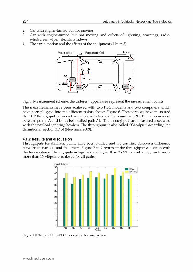
4.1.2 Results and discussion Throughputs for different points have been studied and we can first observe a difference between scenario 1) and the others. Figure 7 to 9 represent the throughput we obtain with the two modems. Throughputs in Figure 7 are higher than 35 Mbps, and in Figures 8 and 9 more than 15 Mbps are achieved for all paths.
Fig. 7. HPAV and HD-PLC throughputs comparison
www.intechopen.com
Experiments of In-Vehicle Power Line Communications
265
For scenario 2), 3) and 4) we remark that the HPAV has the best performances. Moreover, we can observe short variations between the scenarios for the two indoor standards. Furthermore there is a throughput difference according to the path in-vehicle. Indeed, we can see that the path HD has throughput higher than all the others. Indoor PLC standards have been designed according indoor channel characterization. Moreover, the power level of the transmitted signal has been chosen according the indoor CEM constraints. In fact, to respect the vehicle CEM it has been said in (Degardin et al., 2007) that the power level of transmitted signal should be between -60 dBm/Hz and -80 dBm/Hz. This specific point must be taken into account for next PLC in-vehicle transmission. That's why measurements on several vehicles have been achieved and are discussed in the next subsection.
Fig. 8. HPAV throughputs for different paths in-vehicle for scenario 2), 3) and 4)
Fig. 9. HD-PLC throughputs for different paths in-vehicle for scenario 2), 3) and 4)
www.intechopen.com
Advances in Vehicular Networking Technologies
266
4.2 In-vehicle channel measurements In order to design a future PLC modem it is necessary to study the PLC in-vehicle channel. Here the transfer function and the background noise is studied. Additional measurements have been performed on recent vehicles for two classes of paths:
front to front and rear to front (Tanguy et all, 2009). Figure 10 and 11 illustrate the results
according to our testbed (Figure 6). In order to analyze the DC PLC architectures, additional
transfer functions are measured on four different vehicles. The vehicles are classified
according to: the number and type of ECUs, the length of wires, the combustion engine.
4.2.1 Measurement testbed The S-parameters are recorded using a full 4 ports Vector Network Analyzer (VNA) and a
PC interfaced to remote the device. We record the S-parameters during about 10 minutes
while the car is moving. The S-parameters are recorded about every 10 seconds for the 3
different paths: GF, GH and HD. Compared with the previous subsection we have introduce
a new measurement point called G which is for the most of vehicle tested a cigar lighter
receptacle. These paths have been chosen in order to analyze the differences between front
to front and rear to front.
Regarding the noise, the same points have been considered: G, D, F and H. Two different
noise studies have been carried out. The first consists of the measurement of the power
spectrum at each point during 10 minutes every 10 seconds with the vehicle moving. The
second is a measurement in the time domain. In fact, a digital storage oscilloscope (DSO) has
been used to record at each point the signal over the DC line. With this testbed we are able to
record two signals at two different points in the same time. Thus, we can observe the level of
noise at two different points simultaneously. Finally, the measurements have been performed
on a Peugeot 407 SW gasoline and diesel, a Renault Laguna II Estate and a Citroën C3.
4.2.2 Results & discussion Figure 10 and Figure 11 show an example of time and frequency responses for the three
paths GF, GH and HD and for a measurement bandwidth of [1-31] MHz. The impulse
responses have been calculated with the inverse Fourier transform of complex parameter S21.
Fig. 10. Impulse response for 3 paths GF,GH,HD on 407SW gasoline
www.intechopen.com
Experiments of In-Vehicle Power Line Communications
267
Fig. 11. S21 for 3 paths GF, GH and HD on 407 SW gasoline
Table 2. Coherence bandwidth (BC0.9) for 3 paths (GF, GH and HD) and for 4 different vehicles
In a previous study on in-vehicle PLC (Lienard et al., 2008) a delay spread under 380 µs and a coherence bandwidth greater than 400 KHz has been found. Moreover, in Table 2, we observe the coherence bandwidths are different from one vehicle to another and from one path to another. This means that the modulation must be adaptive. Regarding the average attenuation we can also observed differences between the different paths. For example, the Renault Laguna II Estate has a mean average attenuation of 9 dB for the path GF, 31.6 dB for GH and 31.5 for HD. But the 407 SW gasoline has a mean average
www.intechopen.com
Advances in Vehicular Networking Technologies
268
attenuation of 40.1 dB for the path GF, 40.4 dB for GH and 24.4 for HD. Otherwise, we have a maximum average attenuation of 69.3 dB for the path GH of the 407 SW diesel and a minimum average attenuation of 5.8 dB for the path GF of the Laguna II.
Fig. 12. Noise measured with a spectrum analyser for 4 different paths on a Peugeot 407 SW gasoline
Fig. 13. Spectrogram computed with the DSO recording at point G measured on a Peugeot 407 SW gasoline
To optimize the modulation parameters, we have to consider the noise. Figure 12 represents an example of noise measurement with a spectrum analyzer for 4 different points in a Peugeot 407 SW gasoline. We observe an increase of noise for some frequencies in the bandwidth [0 – 5] MHz. Moreover we can see narrowband noises. Like in (Yabuuchi et al.,
www.intechopen.com
Experiments of In-Vehicle Power Line Communications
269
2010) we have applied to noise recordings in-vehicle a time frequency analysis. In Figure 13 we show an example of spectrogram computed with the DSO recording at point G measured on the same vehicle. We have computed the spectrogram with short-time Fourier transform where an Hamming window of length equal to the length of HPAV OFDM symbol (40.96 µs) and an FFT size of 3072 points like in HPAV standard. In Figure 13 we can observe that in the bandwidth [0 – 5] MHz the noise is constant during
the time of the recording. Therefore, in the case of a multi-carriers modulation transmission
in the bandwidth [2-30] MHz some subcarriers will be affected during all the transmission
time.
We have observed that the average attenuation, the coherence bandwidth and the RMS
delay spread are very different according the vehicles, the paths in-vehicle and the paths
between vehicles. We verified the capacity for each paths of each vehicles with the
parameters of the Table 3 according to
1
20
log (1 )N
iC f SNR−= Δ +∑ (1)
with Δf the subcarrier bandwidth, SNR_{i} = (H_{i}2.Pe/Pn) the signal to noise ratio per
subcarrier , Pe is the PSD of the emitted signal and Pn is the PSD of the AWGN noise.
Parameters Values
Fmin 1 MHz
Fmax 31 MHz
Subcarrier N=1228
FFT/IFFT 3072
Δf 24.414 KHz
PSD of noise (Pn) - 120 dBm/Hz
PSD of signal (Pe) -60 dBm/Hz
Table 3. Simulation parameters: FFT/IFFT and Δf values are parameters used by the HPAV standard
The results show the minimum of the average capacity is about 190 Mbps for the path GH
of the Peugeot 407 SW diesel and the maximum is about 507 Mbps for the path GF of the
Laguna II. We observed also differences between the paths and the vehicles.
The vehicles have not the same electrical topology. In fact, it depends on car manufacturer,
the size of vehicles, the number of ECUs ... Therefore the load on the electrical network, the
length of wires and the junctions between cables are different. We have several channels
which are different according the paths and the vehicles like we have shown with the
coherence bandwidth, the time delay spread, the channel gain and the capacities.
The multicarrier modulation seems to achieve good performances like we have seen during
the throughput measurement of HPAV and HD-PLC standards. In this study, only the
www.intechopen.com
Advances in Vehicular Networking Technologies
270
channel function transfer and the background noise have been studied. The impulsive noise
is an other important aspect to take into account (Umehara et al., 2010) and (Degardin et al.,
2008) for powerline communication. According to us the MAC/PHY layers must be
designed to take into account the differences between vehicles and the differences between
paths in-vehicle. Future work will be focus on the integration in a simulator of all the
channel measurements (transfer function, background noise, narrowband interference and
impulsive noise) in order to optimize the modulation scheme.
5. In-vehicle wireless communications
The interest in wireless networking has grown significantly due to the availability of many
wireless products. Looking at in-vehicle communications, more and more portable devices,
e.g., mobile phones, laptop computers and DVD player can exploit the possibility of
interconnection with the vehicle. Wireless communication could be an attractive solution to
reduce the number of cables and disturbances in cars. We have reviewed potential wireless
solutions, specifically two of them in (Nouvel et al., 2009A). We have performed tests similar
to PLC tests in order to qualify the channel in the 2.4 GHz band. Data rate measurements
show it is possible to achieve more than 10 Mbps/s in the vehicle, using also OFDM
technology. Additional studies have been carried out in (Nolte et al., 2009). The authors in
(Zhang et al., 2009) have conducted measurements in the [0.5 – 16] GHz band. One can
observe the different delay profile, different clusters, different paths and the impact of
passengers. Due to lake of space, it is not possible to describe all the measurements. And we
invite the interested readers to look at the papers and chapters.
6. From static to dynamic ECU and communication networks
Taking into account all these networks, from specific network up to PLC or wireless
combined with the constraint of flexibility and security, one attractive idea is to be able to
switch from one network to another one, without additional cost. If the main
communication fails, the ECU ( modem) can switch to the secondary protocol and continue
to run. Reconfigurable architectures based on FPGA may offer very flexible links inside a
vehicle. A dynamically reconfigurable system allows changing parts of its logic resources
without disturbing the functioning of the remaining circuit. This property can applied for
networks, in order to allow changing from one protocol to another one according to the
channel behaviour, errors, load, etc. This section will discuss about this new concept and
demonstrates how it can be integrated in vehicle.
Certain modern FPGAs offer dynamic and partial reconfiguration (DPR – Dynamically and
Partially Reconfigurable) capability that allows to change dynamically one portion of the
FPGA without affecting the rest of the circuit. Currently, the Xilinx Virtex FPGAs (Xilinx,
Inc, 2008) are the only commercially available circuits supporting the DPR paradigm and
large applications implementation. Internal structure of a Xilinx Virtex5 is presented in
Figure 1. The main resources dispatched in the FPGA matrices are slices, DSP blocks
(CMTs) as well as the reconfiguration interfaces, so called ICAP. Slices are the smallest
configurable elements constituted of LUTs (Look-Up Table), registers and logic gates. DSP
blocks offer a powerful set of processing elements for data applications.
www.intechopen.com
Experiments of In-Vehicle Power Line Communications
271
The dynamic reconfiguration takes place in Partially Reconfigurable Region (PRR) which can be partially reconfigured independently. Designing a dynamically self-reconfigurable system always require the declaration of PRRs. A PRR is implemented statically despite the fact that its content is dynamic. Thus, at runtime, dynamic reconfiguration can only take place into the PRR. Communications between a dynamic task and its static environment is assured through the bus macro interfaces. Bus macros are also specified statically.
Fig. 14. View of the Virtex5 5VSX50T captured from Xilinx PlanAhead design tool
The FPGA fabric is partitioned into one static logic and one or more partially reconfigurable
regions (PRRs). This fabric partitioning enables reconfiguration of a single PRR without
system interruption (the static region and other PRRs continue execution while only the
reconfigured PRR halts). Each PRR has a related partial bitstream and the reconfiguration
process can be done by sending this partial bitstream to the reconfiguration port. In modern
FPGAs, the reconfiguration is stored in SRAM based memory, leading to a weakness from a
reliability point of view.
Modern FPGAs, besides customary high-density reconfigurable resources, offer the
designers the possibilities of implementing programmable processors having features of
Commercial Off-The-Shelf (COTS) components (no need to modify processor architecture or
application software). Processors play the role of processing units, and one particular is used
as coordination units in the embedded system. Besides, processors are in charge of collecting
the data from peripherals and from the memory, process the data and send them to the
memory and to the peripherals. Also, processors manage the memory and initialize the
peripherals. Xilinx FPGA devices include two categories of processors: the hardcore
embedded processor (PowerPC) (Xilinx, Inc, 2004) and softcore processors (MicroBlaze,
PicoBlaze) (Xilinx, Inc, 2009). Hardcore embedded processors are hard-wired on the FPGA
die and their number is limited on each device. On the other hand, softcore processors use
reconfigurable resources, so the number that can be actually implemented depends on the
device size only. The MicroBlaze tasks can be classified into 2 types: hardware tasks and
software tasks. Hardware tasks are peripherals connecting to MicroBlaze. Software tasks are
software programs running inside MicroBlazes. Generally, hardware tasks are designed
using High Description Language HDL like VHDL, Verilog and software tasks are
programmed using C. Regardless of their design methods they are presented in our system
www.intechopen.com
Advances in Vehicular Networking Technologies
272
in compiled forms of binary files called bitstreams. A bitstream is the set of binary data
describing the circuits implemented on the FPGA, or in PRRs (partial bitstream). Shorten
term “bitstream 1” will refer to all the bitstreams of FPGA1, idem with “bitstream 2” for
FPGA2, ….
The processor software context is a set of information needed to uniquely define the state of
the processor at a given moment. It could include the states of the processor registers, the
cache, the memory, etc. Saving and restoring all relevant values allow for processor context
switching and error recovery. The softcore processor MicroBlaze context is represented by
the 32-bit values of 32 General Purpose Registers and two Special Registers: the Program
Counter (PC) and the Machine Status Register (MSR).
A MicroBlaze task migration consists in migrating hardware task, software task and
restoring the software context. Hardware task migration requires the appropriate peripheral
to be added using dynamic reconfiguration. Software context is also migrated by dynamic
reconfiguration. And copying the saved software context into the related MicroBlaze
program memory does the software context recovery process.
Due to their flexibility, FPGAs are attractive for mission-critical embedded applications like
automobile domain, but their reliability could be insufficient unless some fault-tolerance
techniques capable of mitigating soft errors are used. Dynamic partial reconfiguration
provide not only the flexibility in both hardware and software, but also further solutions
dealing with reliability problem in critical domains. The dynamic reconfiguration allows the
reloading of the defected module to the correct state and the re-execution of the attributed
tasks. It cans also re-distribute defected tasks in the faulty module to other processing units
in the system.
We present here the feasibility of integrating dynamic reconfiguration features into
automotive-aimed applications in which certain fault-tolerance degrees should be
maintained. In case of a fault occurrence, the system must be capable of react in real-time to
ensure the safety for driver as well as pedestrian. The reaction in this case can be the fast
fault detection and correction by loading the original configuration to put the faulty module
to the state as at start-up. It can also be the critical task migration from the defected module
to another module. To define a new embedded automotive platform based on reconfigurable architecture, in CIFAER (CIFAER, 2008) we advocate for the use of Radio Frequency and Power-Line Communication for intra-vehicle communications (Nouvel et al., 2008). The communication can be switched from one to the other by dynamically reconfiguring a defined communication zone on an FPGA. These two modes offer very flexible links inside a vehicle. Figure 15 shows the fault-tolerant multi-FPGA platform. The system consists of four FPGAs connected together using two Ethernet communication (in future development one will be based on PLC interface, while the other will be constructed on RF connections). The first network is routed via a network switch, the other network form a ring topology for the fault-tolerance purpose. The Ethernet protocol is built by Ethernet controller as MicroBlaze hardware peripherals and LightWeight IP (LightWeight) as the software library. The lwIP is an open-source stack using TCP/IP protocol, which can be easily adapted to PLC and wireless modem. Each FPGA contain a fault-tolerant dynamic multi-processors system, consisting of several MicroBlaze (Figure 16). Further details about this system architecture, called FT-DyMPSoC, as well as the fault-tolerance schemes implemented can be found in (Pham et al., 2009) and (Pham et al., 2010) for interested readers.
www.intechopen.com
Experiments of In-Vehicle Power Line Communications
273
Fig. 15. Fault-tolerant multi-FPGA platform. Two communications networks are supported for reliability purpose
Fig. 16. FT-DyMPSoC Architecture. Included in each FPGA this architecture insert fault-tolerant mitigation schemes
On the overall system, each FPGA is interfaced with a memory that can be accessed by all the processors inside the same FPGA. This memory is partitioned into three segments (Figure 15): - One for saving all the bitstreams and the software contexts of all the processors of this
particular FPGA. - One for saving all the bitstreams of the next FPGA in the ring network. - One reserved and used in case of failure occurrence in the system. This segment helps
to transfer the bitstreams and contexts between different FPGAs. The memory segmentation guarantees the existence of at least one copy of all the bitstreams over the whole network. As we can see in Figure 17, the bitstream of each FPGA is present in its local memory and
also in the local memory of the previous FPGA in the ring topology. For example, FPGA1
stores its own bitstream 1 and and the bitstream 2, FPGA2 stores bitstream 2 and bitstream
3… These copies will be used in case of system failure, and permit fast context switching.
www.intechopen.com
Advances in Vehicular Networking Technologies
274
Fig. 17. Fault recovery strategies. Once the faulty FPGA is identified, the copies of the bitstreams are exchanged in order to keep a valid copy of all the configurations
The fault-tolerance degrees are maintained at two levels in the system. The Intra-FPGA level corresponds to the fault-tolerance strategy inside each FPGA, and is related to the design of the FT-DyMPSoC system. The fault-mitigation strategy is realized using the connection matrices algorithm (Pham, 2009), and fault are mitigated by using dynamic reconfiguration at the processors level. The second level called Inter-FPGA level corresponds to the overall system presented in Figure 15. To detect error in the overall network, all the FPGAs exchange frequently among them detection frames. These frames contain the software contexts of the four MicroBlazes of each FPGAs. On one hand, this helps detecting error in the network. On the other hand, including the contexts within the detection frame will help to resume the tasks of a faulty FPGA on another FPGA. During the exchange if the contexts of one FPGA (i.e. FPGA3 in Figure 17) are not received by the others circuits, the FPGA3 is declared faulty. There are 2 possibilities: the MicroBlaze 1 (supporting the interface to the network) of FPGA3 is faulty, causing the communication lost of this FPGA, or the whole FPGA3 is faulty. In order to distinguish these 2 possibilities, the secondary ethernet links is used. FPGA2 and FPGA4 try to communicate with MicroBlaze 2 and 3 of FPGA3. If these communications fails, the whole FPGA3 is declared defected, if not, only the MicroBlaze 1 is defected. If only one MicroBlaze inside one FPGA fails, we can manage this error thanks to dynamic reconfiguration of this processor or by using task migration within the MPSoC system. The error is managed at the FPGA level. If the whole FPGA fails the task migration concerns the overall circuit. In this case the task of the FPGA3 needs to be dispatched across the remaining circuits. If the system cannot manage all the tasks with one missing FPGA priority needs to be defined and used to maintain critical services for example. In this case, arbitration on the running tasks needs to be executed, and reconfiguration of the remaining FPGA is launched. If one FPGA is lost, we need to maintain the two bitstreams copy stored in the faulty FPGA. For example, if the FPGA3 is lost (Figure 17), the copies of bitstream 3 and 4 are inaccessible requiring a clone of bitstream 3 and bitstream 4. We propose here 2 strategies delivering the bitstream 3 and 4 to other FPGAs. 1. The first strategy uses only the secondary communication media. We need to use
FPGA1 reserved segment as intermediate medium. First the bitstream 4 is copied from FPGA 4 to FPGA1 reserved segment, then to FPGA2. Afterwards, bitstream 3 is copied from FPGA2 to FPGA1, then to FPGA4.
www.intechopen.com
Experiments of In-Vehicle Power Line Communications
275
2. The second strategy requires both communication media. Bitstream 4 is copied from FPGA4 to FPGA1 using direct Ethernet link. Simultaneously, bitstream 3 is copied from FPGA2 to FPGA4 using the primary Ethernet via the switch.
In case the Ethernet switch fails, all the primary Ethernet connections are defected; This leads to a connection loss between all the FPGAS. At this moment all circuits switch to the ring topology. The second network will then ensure proper operation of the overall system. The use of redundancy of the network, coupled with the new dynamically reconfigurable paradigm permits to construct highly reliable system.
7. Conclusion
In this chapter, an initial foreseeable solution with PLC has been presented to allow communications and interoperability between embedded applications with different requirements. PLC network answers both to cost, flexibility and throughput requirements. Future work should be devoted to optimize both PLC modulations and ECU architectures in order to minimize the number of cables and ECU etc. This implies rethinking the DC bundles as rethinking the implementation of networks as independent domain. Furthermore, it is possible to build a reconfigurable ECU for both application and communication. This new concept will allow combining different network technologies. It will answer to fault tolerance constraints, required in X-by-wire applications This work has been carried out by the CIFAER project, supported by the ANR and by the French Premium Cars competitiveness Cluster ID4car.
8. References
Afkhamie, K.H.; Katar, S.; Yonge, L. & Newman R. (2005). An overview of the upcoming HomePlug AV standard, Proceedings of the IEEE International Symposium on Power Line Communications and Its Applications, pp. 400–404, 0-7803-8844-5, 6-8 Apr. 2005, Vancouver, BC, Canada.
Arabia, E.; Ciofi, C.; Consoli, A.; Merlino, R. & Testa A. (2006). Electromechanical Actuators for Automotive Applications Exploiting Power Line Communication, Proceedings of SPEEDAM, pp. 909-914, 1-4244-0193-3, Taormina, 26-26 May 2006
Bahai, A.; Saltzberg, R. & Ergen, M (2004). MultiCarrier Digital Communications, ISBN: (HB) 0-387-22575-7, Springer NewYork
Barmada, S.; Raugi, M.; Tucchi, M. & Zheng, T. (2010). Powerline communication in a full electric vehicle, Proceedings of IEEE International Symposium on Power Line Communications and Its Applications, pp. 331-336, 978-1-4244-5009-1, Rio de Janeiro , 28-31 March 2010
Bassi, E.; Benzi, F.; Almeida, L. & Nolte, T. (2009). Powerline communication in electric vehicles, Electric Machines and Drives Conference, pp. 1749–1753, 978-1-4244-4251-5, Miami, 3-6 May 2009
Beikirch, H. & Voss, M. (2000). CAN-transceiver for field-bus power line communication, Proceedings of the International Symposium on Power Line Communications and Its Applications, Limerick, pp. 257–264, April 2000
Benzi, T.; Facchinetti, T. Nolte & Almeida L. (2008). Towards the powerline alternative in automotive applications, Proceedings of Factory Communication Systems, pp. 259-262, 978-1-4244-2349-1, Dresden, 21-23 May 2008
www.intechopen.com
Advances in Vehicular Networking Technologies
276
CAN. (2009), Retrieved from official web site http://www.can-cia.org/ ( 2009) CIFAER (2008), Communications Intra-véhicule et Architecture Embarquée Reconfigurable,
French ANR Project 2008-2011. Available at web site www.agence-nationale-recherche.fr/AAPProjetsOuverts
Claus, C.; Stechele W. (2010), AutoVision - Reconfigurable Hardware Acceleration for Video-Based Driver Assistance, In: Platzner, Teich, Wehn (Editors): Dynamically Reconfigurable Systems, ISBN 978-90-481-3484-7, Springer, 2010
De Caro S. & Testa, A. (2009). A Power Line Communication approach for body electronics modules, Proceeding of Power Electronics and Applications, pp. 1-10, 978-1-4244-4432-8, Barcelona, 8-10 September 2009
Degardin, V.; Laly, P.; Liénard, M. & Degauque, P. (2006). Impulsive Noise on In-Vehicle Power Lines: Characterization and Impact on Communication Performance, Proceedings of IEEE International Power line Communications and Its Applications, pp. 222-226, 1-4244-0113-5, Orlando, 26-29 March 2006.
Degardin, V.; Lienard, M.; Degauque, P. & Laly, P. (2007). Performances of the Homeplug PHY layer in the context of in-vehicle powerline communications, Proceedings of Power Line Communications and Its Applications, pp. 93-97, 1-4244-1090-8, Pisa, 26-28 March 2007
FlexRay Consortium. (2009). FlexRay Communication System, Protocol Specification, Version 2.0. Retrieved from: http://www.flexray.com
Galli, S.; Koga, H. & Kodama, N. (2008). Advance signal Processing for PLCs: Wavelet OFDM, Proceedings of Power Line Communications and Its Applications, pp. 187-192, 978-1-4244-1975-3, Jeju city, Jeju Island, 2-4 April 2008
Gavette, S. & al. (2006). HomePlug AV Technology Overview, Technical report. Sharp Laboratories of America. Retrieved fromdownload.microsoft.com/download.
Gouret, W.; Nouvel, F. & El Zein, G. (2006). Additional Network Using Automotive Powerline Communication, Proceedings of International Conference on Intelligent Transport Systems Telecommunications, pp. 1087-1092, 0-7803-9587-5, Chengdu, 26-29 March 2006
Gouret, W.; Nouvel, F. & El Zein, G. (2007), High Data Rate Network Using Automotive Power Line, Proceedings of International Conference on Intelligent Transport Systems Telecommunications, pp. 1-4, 1-4244-1178-5, Sophia Antipolis, 26-28 March 2007
IEEE P1901 (2008), IEEE P1901 Working group. Retrieved from web official web site http://grouper.ieee.org/groups/1901/
Home Plug (2009). HomePlug Powerline Alliance. Retrieved from official web site www.homeplug.org
Huck, T., Schirmer, J. & Dostert, K. (2005). Tutorial about the implementation of a vehicular high speed communication system. in IEEE International Power line Communications and Its Applications IEEE ISPLC , pp 162-166, 6-8 April, 2005.
J2056/2 Survey. (1994). J2056/2 survey of known protocols. In SAE Handbook. Warrendale, PA: Soc. Automotive Eng. (SAE), vol. 2.
Leen, G; Hefferman, D. (2001). Vehicles without wires. Computing & Control Engineering Journal, Volume. N° 12(Issue 5), October (pp. 205-21).
Lienard, M.; Carrion, M.; Degardin, V. & Degauque, P. (2008). Modeling and Analysis on In-vehicle power line communication channels, Proceeding of IEEE Transaction on Vehicular Technology, vol 57, N°2, pp. 670-679, 0018-9545
www.intechopen.com
Experiments of In-Vehicle Power Line Communications
277
LIN Consortium. (2003). LIN Specification Package, Revision 2.0.Retrieved from http://www.lin~subbus.org/( 2009)
Mohammadi, M.; Lampe L.; Lok, M.; Mirabbasi, S.; Mirvakili, M.; Rosales, R. & Van Veen, P. (2009). Measurement study and transmission for in-vehicle power line communication, Proceedings of IEEE Power Line Communications and Its Applications, pp. 73–78, 978-1-4244-3790-0, Dresden, 29-March -1 April 2009
Navet (2008), The Automotive Embedded Systems Handbook, Industrial Information Technology series, Taylor and Francis , CRC Press, ISBN 978-0849380266, 2008.
Newman, D. (2009). Benchmarking Terminology for Firewall Performance, RFC 2647. Nolte,T. ( 2006). Share-Driven Scheduling of Embedded Networks. University, Dissertation,
May 2006. Department of Computer Science and Engineering Mälardalen University Västeras, Sweden, Printed by Arkitektkopia, Västeras, Sweden Distribution , 2006
Nolte,T. & Hansson H.( 2009). Wireless Automotive Communications, Internal Report available at http://ant.comm.ccu.edu.tw/course/97_ITS/1_HW1/0.Wireless%20Automotive%20Communications.pdf ,2009
Nouvel, F.; El Zein, G. & Citerne, J. (1994). Code division multiple access for an automotive area network over power-lines, Proceedings of IEEE Vehicular Technology Conference, pp. 525–529, 0-7803-1927-3, Stockholm, 8-10 June 1994.
Nouvel, F. & Maziéro, P. (2008). X-by-Wire and intra-car communications: power line and/or wireless solutions, Proceedings of International Conference on Intelligent Transport Systems Telecommunications, pp. 443-448, 978-1-4244-2857-1, Phuket, 24 October 2008.
Nouvel, F; Gouret, W; Maziéro (2009a), Automotive Network Architecture for ECUs Communications, in Automotive Informatics and Communicative Systems: Principals in Vehicular Networks", 28 pp, 2009, ISBN 978-160566338-8, 2009
Nouvel F.; Tanguy, P. & Maziero P. (2009b), What is about next high speed power line communication systems for in -vehicle networks, Proceedings of ICICS, pp. 533-537, 978-1-4244-4656-8, Macau, 8-10 December 2009
OMEGA (2008), Deliverable D3.1 State of the art, application scenario and specific requirements for PLC, OMEGA ICT-213311 Project, FP7, Available on web site http://www.ict-omega.eu/fileadmin/documents/deliverables/Omega_D3.1.pdf
Pham, H.-M.; Pillement S. & Demigny, D. (2009) A Fault-Tolerant Layer For Dynamically Reconfigurable Multi-Processor System-on-Chip, in Proc. Int. Conf. on ReConFigurable Computing and FPGAs, pp. 284–289, Cancun, Mexico, Dec. 2009.
Pham, H.-M.; Pillement, S. & Demigny, D. (2010) Evaluation of Fault-Mitigation Schemes for Fault-Tolerant Dynamic MPSoC, in Proc. Int. Conf. on Field Programmable Logic and Applications, 2010
Rubin, A. (2002). Implementing automotive protocols for communications over noisy battery power lines, Proceedings of the IEEE Conference on Conv. Elect Electron. Eng., pp. 306, 1 December 2002
Ribeiro. et al. (2006) Power Line communications : a promising communication system paragidm for last miles and meters applications, Telecommunications : Advances and trends in transmissions, pp. 134-154 , ISBN 85-98876-18-6.
Silva, P.; Almeida, L.; Caprini, D.; Facchinetti, T.; Benzi, F. & Nolte, T. (2009). Experiments on timing aspects of DC-powerline communications, Proceedings of IEEE
www.intechopen.com
Advances in Vehicular Networking Technologies
278
international Conference on Emerging Technologies & Factory Automation, pp. 1674-1677, 978-1-4244-2727-7, Palma de Mallorca, Spain, September 22-25 2009
Spidcom (2008). Spidcom Inc., Retrieved from official web Official web site http://www.spidcom.com.
Tanguy P.; Nouvel, F. & Maziéro, P. (2009b), Power Line Communication standards for in-vehicle networks, pp. 533-537, 978-1-4244-5347-4/09, Lilles, 20-22 October 2009
Tanguy, P.; Nouvel, F. (2010). In-Vehicle PLC Simulator Based on Channel Measurements, in next Proceedings of International Conference on Intelligent Transport Systems Telecommunications, Kyoto, 9-11 November 2010.
Umehara, D.; Morikura, M.; Hisada, T.; Ishiko S. & Satoshi, H. (2010). Statistical Impulse Detection of In-Vehicle Power Line Noise Using Hidden Markov Model, Proceedings of Power Line Communications and Its Applications, pp. 341-346, March 2010.
Valéo (2006). Valéo Inc., Electrical and Electronic Distribution Systems: Focus on Power Line Communication. Retrieved from official web http://www.valeo.com
Xilinx, Inc (2004). PowerPC 405 Processor Block Reference Guide, 2004 Xilinx, Inc (2008). Early Access Partial Reconfiguration User Guide UG208, September 2008. Xilinx, Inc (2009). MicroBlaze Processor Reference Guide UG081 (v10.3), 2009 Yamar, 2009, http://www.yamar.com, last access 20.09.2009 Yabuuchi, Y.; Umehara, D.; Morikura, M.; Hisada, T.; Ishiko ,S. & Horihata, S. (2010).
Measurement and Analysis of Impulsive Noise on In-Vehicle Power Lines, Proceedings of Power Line Communications and Its Applications, pp. 325-330, March 2010.
Zhang, N.; Zhu, X.; Liu, L.; Yu, C.; Zhang, Y.; Dong, Y.; Zhang, H.; Kuai, Z. & Hong, W. 2009. Measurement and characterization of wideband channel for in-vehicle environment. In Proceedings of the 4th international Conference on Radio and Wireless Symposium (San Diego, CA, USA, January 18 - 22, 2009). IEEE Press, Piscataway, NJ, 183-186.
www.intechopen.com
Advances in Vehicular Networking TechnologiesEdited by Dr Miguel Almeida
ISBN 978-953-307-241-8Hard cover, 432 pagesPublisher InTechPublished online 11, April, 2011Published in print edition April, 2011
InTech ChinaUnit 405, Office Block, Hotel Equatorial Shanghai No.65, Yan An Road (West), Shanghai, 200040, China
Phone: +86-21-62489820 Fax: +86-21-62489821
This book provides an insight on both the challenges and the technological solutions of several approaches,which allow connecting vehicles between each other and with the network. It underlines the trends onnetworking capabilities and their issues, further focusing on the MAC and Physical layer challenges. Rangingfrom the advances on radio access technologies to intelligent mechanisms deployed to enhance cooperativecommunications, cognitive radio and multiple antenna systems have been given particular highlight.
How to referenceIn order to correctly reference this scholarly work, feel free to copy and paste the following:
Fabienne Nouvel, Philippe Tanguy, S. Pillement and H.M. Pham (2011). Experiments of In-Vehicle Power LineCommunications, Advances in Vehicular Networking Technologies, Dr Miguel Almeida (Ed.), ISBN: 978-953-307-241-8, InTech, Available from: http://www.intechopen.com/books/advances-in-vehicular-networking-technologies/experiments-of-in-vehicle-power-line-communications