Page 1
UNIVERSIDADE FEDERAL DO RIO GRANDE DO SUL
INSITUTE OF COMPUTING
COMPUTER SCIENCE COURSE
GERMANO THOMAS
Expert System for Device Ranking
End of Course Paper.
Prof. Dr. Rosa Maria Vicari
Advisor
M.Sc. Claudia Nass
Co-Advisor
Porto Alegre, July 2012.
Page 2
UNIVERSIDADE FEDERAL DO RIO GRANDE DO SUL
Rector: Prof. Dr. Carlos Alexandre Netto
Vice-Rector: Dr. Rui Vicente Oppermann
Graduation Dean: Dr. Valquiria Linck Bassani
Director of Institute of Computing: Prof. Dr. Luís da Cunha Lamb
Computer Science Coordinator: Dr. Raul Fernando Weber
Chief Librarian of Institute of Computing: Beatriz Regina Bastos Haro
Page 3
ACKNOWLEDGEMENTS
I want to express my gratitude to my parents for my education, care and constant
support. I want to thank my advisor, Rosa Maria Vicari, for her advises and time; and
also to Ricardo Naisse, for helping me in the integration with the Fraunhofer institute.
This project would be impossible without all the great opportunities that UFRGS had
offered.
Page 4
TABLE OF CONTENTS
LIST OF ACRONYMS ................................................................................... 6
LIST OF FIGURES ........................................................................................ 7
LIST OF TABLES ......................................................................................... 8
RESUMO ...................................................................................................... 9
ABSTRACT ................................................................................................ 10
1. APPROACH ...................................................................................... 11
1.1 Multi-criteria Evaluation ...................................................................................................... 11
1.2 State of Art ............................................................................................................................. 12
2. REQUIREMENTS SCHEMA FOR INTERACTION DEVICES ........... 15
2.1 Requirements Decision Model TORE .................................................................................. 15
2.2 Requirements for the Selection of Interaction Devices ...................................................... 17
3. METHOD FOR THE SELECTION OF INTERACTION DEVICES ..... 19
3.1 Requirements Models ............................................................................................................ 19
3.2 Device Model .......................................................................................................................... 20 3.2.1 Suitability ....................................................................................................................... 21
3.3 Expert Knowledge ................................................................................................................. 22
3.4 Programming Language ....................................................................................................... 22
4 IMPLEMENTATION OF THE EXPERT SYSTEM ................................. 24
4.1 Choosing the Expert System ................................................................................................. 25
4.2 Metafacts ................................................................................................................................ 26
Page 5
4.3 Rule Modeling ........................................................................................................................ 27 4.3.1 Rule Types ..................................................................................................................... 28 4.3.2 Conditions and Actions .................................................................................................. 29 4.3.3 Rule Loading ................................................................................................................. 30
4.4 Creating and updating Device Database ............................................................................. 31
4.5 Knowledge session ................................................................................................................. 34
4.6 Interface ................................................................................................................................. 34
5 PROGRAM EXECUTION ...................................................................... 39
CONCLUSION ............................................................................................ 41
REFERENCES ............................................................................................ 43
ATTACHMENT DROOLS USERS AND SOFTWARE OFFERING DROOLS INTEGRATION ................................................................................................. 46
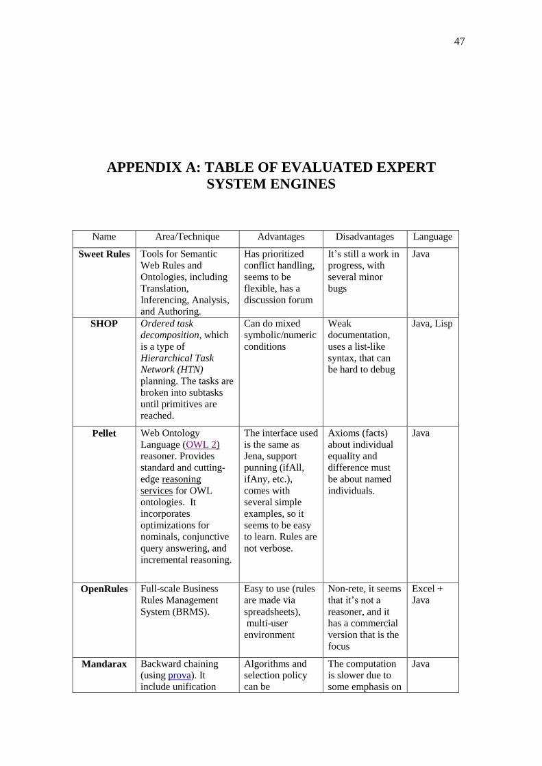
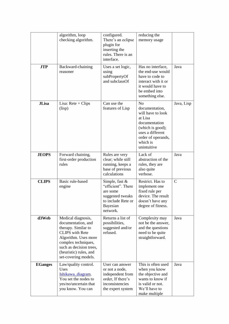
APPENDIX A: TABLE OF EVALUATED EXPERT SYSTEM ENGINES ... 47
APPENDIX B: CLASS DIAGRAMS OF THE REQUIREMENTS ................ 50
APPENDIX C: CLASS DIAGRAM OF THE DEVICE .................................. 54
Page 6
LIST OF ACRONYMS
MCE Multi-criteria evaluation
MCDM Multi-criteria decision making
MCDA Multi-criteria decision aid
ADiWa Alliance digital warenfluss
IESE Institute for experimental software engineering
ES Expert system
UI User interface
GUI Graphical user interface
EMF Eclipse modeling framework
DRL Drools rule language
WYSIWYG What you see is what you get
Page 7
LIST OF FIGURES
Figure 2.1: Scheme of requirements‟ origin ................................................................... 15 Figure 2.2: Fraunhofer Decision Model TORE .............................................................. 15 Figure 2.2.1: TORE with highlighted used decision points ........................................... 17 Figure 3.1.1: Activity class diagram ............................................................................... 20 Figure 4.1.1: ES selection scheme .................................................................................. 25 Figure 4.2.1: Metafact declaration code ......................................................................... 26 Figure 4.3.1.1: Rule types scheme .................................................................................. 29 Figure 4.3.2.1: Simplified rule model............................................................................. 30 Figure 4.3.3.1: Rule loading scheme .............................................................................. 31 Figure 4.4.1: Google Squared smartphones search ........................................................ 32 Figure 4.4.2: Levenshtein distance from house to hostel ............................................... 33 Figure 4.6.1: Loading window ....................................................................................... 34 Figure 4.6.2: GUI of the software of this work .............................................................. 35 Figure 4.6.3: Simplified Options menu and submenus .................................................. 35 Figure 4.6.4: Simplified File menu and submenus ......................................................... 36 Figure 4.6.5: GUI of the software of this work with device rank................................... 36 Figure 4.6.6: Example of combo box in use, User 0 is selected ..................................... 37 Figure 4.6.7: Example of device rank with applied rules ............................................... 37 Figure 4.6.8: Example of option dialog .......................................................................... 38 Figure 4.6.9: Example of warning dialog ....................................................................... 38 Figure 4.6.10: Example of error dialog .......................................................................... 38 Figure 5.1: Program execution scheme .......................................................................... 40
Page 8
LIST OF TABLES
Table 3.2.1: Example of devices to be ranked ................................................................ 22 Table 3.2.2: Example of device ranking ......................................................................... 22
Page 9
Sistema especialista para ordenamento de
dispositivos
RESUMO
Torna-se cada vez mais comum o uso de dispositivos eletrônicos não apenas como
ferramenta de trabalho, mas também como auxílio à atividade a ser executada. Na área
de logística da empresa ADiWa, diferentes partes interessadas desempenhando
diferentes papeis devem lidar com a mesma informação em locais possivelmente
distintos, como escritórios, áreas de estoques ou até em veículos, caracterizando um
problema de multi-criteria. Essa informação deve ser mostrada pelo dispositivo
adequado em termos de tamanho, autonomia e muitas outras características. Decidir
qual o melhor dispositivo em relação a todas essas informações não é tarefa fácil,
portanto o uso de um sistema de apoio à tomada de decisão torna-se fundamental.
A ADiWa contratou a organização Fraunhofer para desenvolver o sistema de apoio.
Fraunhofer é a maior organização de pesquisa aplicada da Europa, com mais de 80
institutos de pesquisa. Seus clientes incluem companhias da indústria, de serviços e
também órgãos públicos. O Fraunhofer Institute for Experimental Software Engineering
(IESE) usa métodos com base empírica e processos para software voltados para a
indústria, assim como o desenvolvimento de sistemas.
No contexto do Fraunhofer IESE foi desenvolvida uma ferramenta que, dadas várias
características de uma empresa, da tarefa a ser executada, do ambiente dessa tarefa e do
perfil do usuário do dispositivo, entre outros aspectos, retorna uma lista de dispositivos
ordenados pela sua adequação àquelas características e auxilia o processo de decisão.
Fraunhofer é a maior organização de pesquisa a aplicada da Europa. Isso foi feito
usando-se Drools, uma plataforma de integração de lógica de negócios que oferece um
sistema especialista baseado em regras e eventos.
Sistemas especialistas tentam imitar as habilidades de decisão de um humano sobre
um domínio específico e podem ser considerados o primeiro grande sucesso da
Inteligência Artificial. Surgiram na década de 70 e se popularizaram na década de 80,
sendo reconhecidos como uma ferramenta capaz de resolver problemas reais. Uma das
áreas de aplicação é o suporte à decisão em sistemas complexos, como é o caso deste
trabalho.
No primeiro capítulo o problema vai ser caracterizado (como multi-criteria) e
soluções para problemas similares serão apresentadas. No segundo capítulo serão
explicados os requerimentos e suas origens. O terceiro capítulo trata da modelagem dos
requerimentos e dos dispositivos, que inclui o atributo “adequação” que será usado na
solução. No quarto capítulo é descrito o desenvolvimento do programa, da escolha do
sistema especialista até o desenvolvimento da interface gráfica com o usuário. No
quinto capítulo é feita uma breve descrição do funcionamento do programa.
Palavras-Chave: Dispositivo, Sistema Especialista, Drools, Multi-criteria.
Page 10
ABSTRACT
It is becoming increasingly common the use of electronic devices not only as a
working tool but also as an aid to the activity being performed. In the logistic of the
company ADiWa different stakeholders playing different roles must deal with the same
information in different places such as offices, areas of inventory or even vehicles,
featuring a multi-criteria problem. This information should be displayed for the
appropriate device in terms of size, autonomy and many other features. Deciding the
best device for all this information is not an easy task, so the use of a support system for
decision making is fundamental.
ADiWa hired the Fraunhofer organization to develop the support system. Fraunhofer
is the largest organization for applied research in Europe, with more than 80 research
institutes. Its contractor and clients include industrial companies, service companies and
the public sector. The Fraunhofer Institute for Experimental Software Engineering
(IESE) stands for empirically based methods and processes for industrial software and
systems development.
In the environment of Fraunhofer IESE was developed a tool that, given various
characteristics about the company, the task to be performed, the environment of the task
and also about the user of the device, among other things, returns a device rank by the
suitability with those characteristics and this rank will assist the decision-making. This
was done using Drools, an integration platform that provides business logic of an expert
system based on rules and events.
Expert systems attempt to mimic the abilities of a human decision-making ability
about a specific domain and can be considered the first great success of Artificial
Intelligence. Emerged in the 70s and became popular in the 80s, being recognized as a
tool to solve real-world problems. One area of application is the decision support in
complex systems, such as in this study.
In the first chapter the problem will be characterized (as multi-criteria) and solutions
to similar problems will be presented. In the second chapter will be explained the
requirements and their origins. The third chapter deals with the modeling of applications
and devices, which includes the attribute "suitability" to be used in the solution. The
fourth chapter describes the development of the program, from the choice of the expert
system to the development of graphical user interface. In the fifth chapter there is a brief
description of the operation of the program.
Keywords: Device, Expert System, Drools, Multi-criteria.
Page 11
11
1. APPROACH
In a company there are several entities that will engage in the choosing of the device
for the employers. To choose the most suitable (or adequate) device is not an easy job.
It is not an attempt to make an usability evaluation, because that would focus only on
the user interface (UI) and part of the system design [24]; it‟s a lot more than that. The
whole process to determine suitability will deal with needs and necessities called
requirements and each of them will have several attributes, which influences differently
on the suitability of the devices. The decision-makers have to decide which device is the
best one, but sometimes even defining what is a good device is not clear. They are
likely to conflict on their decisions, so the software of this work will have to aid the
decision making in a transparent and natural process.
One of the concerns in the design phase of the developing the software was to define
the solution to be reached. To simply try to find the device that meets all the
requirements would often lead to no device at all; in the other way, if the requirements
are in limited number or just are easy to match, a large number of devices would be a
viable option and the decision would rely almost only on the decision makers. The goal
of the software of this work is to compare the devices in terms of requirements to order
them and the solution will be a rank, on which the most suitable device will be the first.
Determining the suitability of the device depends of several things. What is very
important to one requirement may not be that influent to other, therefore each
requirement can be seen as different criteria, making this work similar to a multi-criteria
evaluation (MCE)1. MCE is used when there are variables that cannot be directly
compared between each other and/or when their influence is strong but not
deterministic. It also can handle a large number of data, relations and objectives in a
multidimensional fashion[1][2]. Another characteristic that makes MCE a good option
is that it can handle the mixture of attribute types. The attributes of each requirement
will be mostly nominal; although cardinal, interval and ratio attributes will also be
present. This can be seen as a mixture of qualitative and quantitative data.
1.1 Multi-criteria Evaluation
This section will explain a little more the characteristics of a MCE and how it relates
to the decision making.
MCE is a good solution for the conflicting requirements of this work and Nijkamp
express that:
1 MCE is also known as multi-criteria analysis.
Page 12
From an operational point of view, the major strength of multi-criteria
methods is their ability to revolve questions characterized by various
conflicting evaluations. Multi-criteria evaluation techniques cannot solve all
conflicts, but they can help to provide more insight into the nature of
conflicts thus increasing the transparency of the choice process (1998).
Algorithm solutions to multi-criteria problems tend to leave the problem
unstructured and improvements are harder to be implemented. Making structures for the
decision situations and modeling the preferences of the decision makers are important
steps for any decision methodology. Additionally a solution that is optimal for all
criteria it‟s unlike to exist[4].
MCE may be disjointed into two types: the solutions that use one mathematical
formula can be identified as Multi-criteria decision-making (MCDM) and can only be
applied when the preferences of the decision maker are also bound to a formal and
explicit specification[1], which will be often difficult to achieve. What we will use in
this work is the other type, the Multi-criteria decision aid (MCDA). The objective is to
build something, in this case a rank and the rules applied to each device, that will guide
the process and shape the preferences of the decision makers.
The search for the solution explores the objectives in a way that the understanding of
the problem is easier and the justification of the decision is clearer[3]. Also, “It makes it
possible to analyze the trade-offs between different objectives and concerns, thus
supporting the analysis of the pros-and-cons of different options in a transparent and
effective way” (BEINAT, 1998).
To form a rank, the devices will have to be evaluated and compared with each other.
Comparison may not be simple. The different types of comparability can be seen below:
• Strong comparability: all options may be ordered in one single measurement
scale. Strong comparability is divided in strong commensurability, in which
the options will be measured in a cardinal scale; and weak commensurability,
in which the options will be measured in an ordinal scale (a rank).
• Weak comparability: one option may prevail over another in one criterion, but
lose in other, making their comparison more difficult. This has the
characteristics of incommensurability, which means that options cannot be
compared using a single measurement scale, so other approaches must be
used.
The aim of the software is taking devices with weak comparability and creating a
rank, which implies in strong comparability.
1.2 State of Art
MCE aids the identification of the most suitable solution for a given purpose,
including management solutions, multiple decision alternatives and land-use options
[3]. Below some cases of MCE being used into the site selection field will be presented.
These lands range from urban planning and industrial locations to agricultural
watersheds.
The MATISSE[6] is a software that aids the choosing of a new location for an
industrial company and is the acronym to “Matching Algorithm, a Technique for
Page 13
13
Industrial Site Selection”. The objective is to find locations that meet the spatial
production requirements according to the organizational characteristics of the firm. The
problem is that there are many factors that have to be taken in account: accessibility,
investments and operation are considered together with other ones.
Just to exemplify, the site accessibility is broken in three directives: raw materials
transportation, finished goods transportation, and the transportation of workers from and
to that site. These directives may conflict, and to match the sites to the sets of
requirements they use a knowledge based decision support system (KSS) and decision
tables, which display actions according to the result of relevant conditions.
The software of this work does not use decision tables, but, as in MATISSE, a
knowledge based system is used to display the results according to relevant conditions.
In fact, choosing a location according to the firm‟s characteristics and requirements is
similar to find a device according to the characteristics of the firm, the user and other
requirements. Another noticeable similarity is that they use the term „site suitability‟.
On the other hand, the agricultural site selection also is characterized as a MCE[7].
As the ground conditions may not be perfect, the weather is also a problem. Droughts or
a low quality land will result in reduced crops production. Weather prediction and
statistics will be an indicator, but the lack of water can be handled by artificial
irrigation, which adds the problem of efficient water supply. Therefore, the watershed
will also play an important role on the land suitability.
In a study about watersheds by Reshmidevi, Eldho and Jana (2009), a fuzzy expert
system was made. 16 attributes were identified and were classified in “surface water
potential” or “land potential”. It was discovered that such a simple classification to use a
fuzzy system would demand too much work, so they made 5 intermediary groups and
the result of each one was used in a rule-based system to estimate the suitability.
That is an interesting study for this work because it is an expert system solving a
multi-criteria problem. One distinct characteristic of the solution is the creation of
intermediary groups, which can be compared to our requirements. They also solve the
MCE by using a ruled-based system and expressing it in the form of IF-THEN rules. It
will be explained further that our rules also have conditions and actions.
Forest planning also has a multi-criteria related work[8]. It uses multi-criteria
approval voting. Voting is a method known by almost everyone. It is a simple, yet
efficient, way of making choices among decision alternatives. There are several types of
voting methods and they have in common is that decision makers vote on the
alternatives and the alternative with the most votes is the winner. We are using a voting
system in this work, and some voting methods will be explained below.
The most used voting method is the plurality voting, on which each decision maker
give one vote to the best candidate in his/her view (e.g. elections). One issue with this
type of voting is that one decision maker may influence others to vote on the candidate
of his/her choice. To avoid manipulations, another voting method was proposed: the
approval voting, on which each decision maker vote on all candidates that he/she
approves. It‟s harder to manipulate, but tends to “elect” mediocre candidates. Fraser and
Hauge (1998) state that “The overall objective of approval voting is to elect a candidate
that is widely acceptable to many decision makers, which is parallel to the objective of
MCDM which is to select an alternative that satisfies many criteria.“. There are some
Page 14
other voting methods, and the one that we are using in the software is similar to
approval voting.
Since each decision maker will separate the candidates (devices) into two groups,
the approved and the disapproved ones, the only thing left to each of them is to
determine the threshold between the two groups. The software will simulate voting
decision makers, each one will be a rule and the threshold will be explicit on its
condition. The sum of the votes of a device is called suitability and it‟s one of its
attributes. The suitability and the rules will be explained further in this work.
Page 15
15
2. REQUIREMENTS SCHEMA FOR INTERACTION
DEVICES
A requirements specification is the consistent, complete, unambiguous, correct,
verifiable, traceable documentation of the requirements on a system written in notations
that are understandable to the respective stakeholders. The requirements of this work are
divided in 8, depending on their actors and its actions. This chapter will explain what
the Requirements Decision Model TORE (Task Oriented Requirements Engineering) is
and how the 18 decision points of this model are related to our 8 requirements.
Figure 2.1: Scheme of requirements‟ origin
2.1 Requirements Decision Model TORE
TORE – Task Oriented Requirements Engineering – is a decision model for the task
oriented elicitation and specification of requirements. It has been developed by
Fraunhofer IESE[18] and since was applied successfully in several projects.
TORE encapsulates 18 decisions on four different levels of abstraction that typically
have to be made during requirements engineering for information systems (see figure
2.2).
Figure 2.2: Fraunhofer Decision Model TORE
Page 16
The benefit of thinking in these decisions is that TORE can serve as a conceptual
model independent of concrete processes or notations, allowing high applicability in
many different contexts.
As a basis for the requirements specification, decisions must be made regarding the
design of the context and the system. Since one cannot deal with all the aspects at the
same time, one must decide the order of the decisions. The context may demand more
focus for specific decisions, but all of the decisions must be made; regarding goals,
tasks, technical needs, system usage and system design.
Tasks may be considered the basis for the other decisions. Customers, users, and
other stakeholders have goals that are operationalized by means of tasks. These tasks
are supported by systems. If these systems are developed in a task-oriented manner,
each system feature can motivate and constructively ensure that goals are achieved.
Additionally, both scientific experts and developers understand the concept of tasks, so
a communication bridge is created between them.
TORE is divided into five levels:
1. Goal and task level: helps deciding which stakeholders is the system useful for
and what are their goals and tasks. Profiles and personas are created for each
stakeholder, goals are represented via AND / OR trees, and individual core
features of the system are derived from these. Tasks are identified and later
described by means of observation, study of documents and events in
business processes and business interactions, surveying entities directly
related to the users, like marketing, sales, hotline, coaches, or by directly
surveying the users.
2. Domain level: helps deciding which data are important in the domain, what the
concrete responsibilities of the system will be, how the tasks change with the
introduction of a system and how the tasks are currently performed. Not only
tasks are identified, but also tasks workflows. Task workflows are described
in structural text or may be represented graphically (e.g., by using UML
diagrams). Tasks are refined into activities. As-Is activities are identified, To-
Be activities are defined. System responsibilities (system-supported To-Be
activities) are classified into system activities, user activities, and system-
supported activities. Finally, the data is described and dependencies are
defined.
3. Interaction level: helps deciding which functions the system offer, how the user
interact with the system, which data are exchanged between the user and
system and how the overall functionality is divided into sub-functionalities.
For each activity, at least one Use Case is created. These are then used to
create a Use Case diagram. In order to avoid redundancy, the Use Cases are
optimized, then prioritized and bundled. In doing so, exceptions and quality
requirements are also included. Functions and data that belong together are
grouped into work areas.
4. System level (application core): helps deciding what the GUI looks like
concretely, how can the user actually work with the GUI, what the system
architecture looks like, which internal data schemas are there and which
function building blocks exist.
Page 17
17
5. System level (GUI): helps deciding how the data is represented on the screen,
how the functions are offered on the screen, how the user can monitor the
execution of a function and which help functions are necessary to monitor
calculations as well as navigation between screens. Design laws and text
guidelines must be followed, and perception effects must be taken into
account. Dialogs can be described as state transition diagrams. The elements
of the GUI level can be developed in parallel, but must be continually
aligned with each other. Screen structure and UI data are derived from the UI
structure and by doing so, the navigation functions are defined. Then dialog
models are created for complex Use Cases, which are integrated into an
overview diagram. In this step, semantic help functions are introduced.
Finally, the screen structure is refined.
2.2 Requirements for the Selection of Interaction Devices
From the 18 decision points of TORE, 7 were used to describe the 8 requirements of
this work, half of them belong to the first abstraction level (Goal and task) and the other
half belong to the second (Domain) and third (Interaction) level. None of them belongs
to the fourth (System) level. The used decision points are highlighted in figure 2.2.1.
Figure 2.2.1: TORE with highlighted used decision points
The reason for this distribution in the firsts levels is that the interaction with the
Devices differs more on hardware and what the hardware offers to the User than on
which System and applications it supports. The eight decision points were classified in
seven Requirements as described below:
• Activity: the TORE name for this Requirement is “To-Be Activities”; it
describes some general information about the tasks and processes to be
performed. This includes input and output for the activities, their types (that
can be store modify or show), number of people working in parallel in the
same device and what type of activities should have a higher priority. Those
types are: Input, Retrieval (or output) and Modification.
• Stakeholder tasks: this Requirement is the only one that covers two decision
points: Supported Stakeholders and Stakeholder`s Tasks; it describes more
Page 18
accurately the activities, defining the type, input, processing and output of a
task, as well as in how many dimensions an object will be shown or
modified.
• Domain data: describes how the data will be transferred (communication
interface) and represented (numbers, text, images, movies or sounds) by the
Device. The amount of the data is also described by this requirement.
• Environmental context: describes the working place of the User. It includes what
will influence on the User senses, such as noise and brightness, which will
make interaction harder, and also what will add needs to the Devices, such as
temperature resistance or energy supply. Some aspects will influence both
Users and Devices, such as moving or static working place and distance from
the User to the device.
• Goals and constraints: this describes relevant information about the company.
Goals are company`s interests or focus. It can be the style of the device, its
color or also usability, which can be higher efficiency, more effectiveness or
higher employee satisfaction. Constraints in the other way denotes the
company`s restrictions, such as money. The decision point of this
requirement is the Stakeholder‟s Goals.
• Interaction: this requirement describes how the User interacts with the device. It
considers what body part of the user is interacting. It can be hand, foot or
voice, the precision or coordination needed and the interaction type, which
can be enter a text or a value, draw a line or interactions with objects, such as
select, position and orient. Those object interactions can be in one, two or
three dimensions.
• Interaction data: this is about the representation and some resources that should
be available. It includes colors, two/three-dimensional representations and
detail levels.
• User: this requirement describes the person that will be using the Device. It
includes education, occupation, technical affinity, languages and physical
characteristics like age, gender, senses used as well as limitations such as
impairments. User is a supported stakeholder.
To avoid misunderstandings between the decision maker that will be using the
software and the Requirement User, the first one will be called “end-user” from now on.
Page 19
19
3. METHOD FOR THE SELECTION OF
INTERACTION DEVICES
Each Requirement will influence the selection of the Device in different ways. The
end-user will have to inform the characteristics of the Requirements so the software can
work on them. This set of the informed characteristics is called Scenario. To know
which Device is the best for a given Scenario, a Device rank will be made. With this
rank it will be possible not only to know which one to use, but also to compare them
with each other. Together with the rank will be also a track of the activity, so the end-
user can know why the Device is on that position in the rank.
The software will use an Expert System (ES) engine to build the rank via approval
voting. We need to create a set of Devices candidates that will be evaluated depending
on the Scenario inputted by the end-user. The correlation between Scenario and Devices
will be done with rules that, among other things, will evaluate how suitable each Device
is for that Scenario. The Requirements, the Devices and the rules need to be modeled to
be used by the engine.
3.1 Requirements Models
Models try to capture real-world behaviors and give structure to them. They are
useful to organize and split concepts into smaller and simpler elements that can be read
more clearly. The use of models also makes maintenance easier[22]. Concepts can infer
several semantics, but models should be formal enough to be interpreted
unambiguously. They can be used by team members to communicate with each other.
The relation between Requirements and Devices will be clearer if there is a way to
represent both of them. In order to use the Scenario, we need to express it in a more
formal shape to be understood by the developers and the machine. It has to be
constrained enough to avoid distortions on its representation, but flexible enough to
cover a big range of Scenarios in an easy and clear way.
The Requirements Schema for Interaction Devices can be called our Conceptual
model, and there is one Domain model (or class diagram[10]) for each Requirement.
Each model specifies several attributes, which are the characteristics of that
Requirement, such as `Gender` of the Requirement User. Most of the times the value of
the Attribute is not a number, but belongs to a limited set of elements, such as `Male` or
`Female` of the attribute `Gender`. Each of these elements is called attribute instance.
The 8 Requirements have a total of 39 attributes and 195 attribute Instances. Below
there is the Activity class diagram as an example; all 8 requirements‟ diagrams can be
seen in Appendix B.
Page 20
Figure 3.1.1: Activity class diagram
In the diagram, the main class has the same name as the Requirement. The
requirement attributes consist of the attributes of the main class and its getters. The
requirements attributes, plus the attributes inside the getters are called Instances. If an
attribute is an enumeration, each of its items will be counted as an Instance instead of
the enumeration itself. Careful not to mistake the Instances of the attributes with the
instances of the Requirements; when the end-user creates an object of the main class it
will also be called an instance, but the context is other. The end-user will be able to
create new instances for each requirement and they will be stored in the database
(bottom of figure 3.1.1).
The instances describe a type, a general idea and not an individual entity of that
Requirement. E.g. when we create an User Requirement we do not specify one person,
but the general characteristics of that type of User. An User with the Instance `male`
does not mean that this User have to be `male`, but that in most cases it will be. It even
can be `Male` and `Female` at the same time, indicating that both genders can execute
that task. Furthermore, the identification of an User is not made by a born name, but
with a label just used for identification, like `Young driver`. This happens with all the
Requirements.
The Domain models of the Requirements are already a form of knowledge base and
will be broadly used in the development of the software. Classes and attributes are built
directly from them, in a very transparent way. Modifying the models is unadvised, but if
becomes necessary, it will not require much rework because of the objectivity and
clearness that the translation is done.
3.2 Device Model
The Devices will form a set of candidates that will be ranked and our goal is to
create a fair rank. The better the Devices are modeled, the closer the result will be in the
software and in the real world. The rules will also be more effective with proper
modeling. Differently from the Requirements, the Device model will usually define a
specific Device and not the type or a category.
Page 21
21
The model describes the device hardware such as weight, size, battery and operating
temperatures; peripheral such as screen, speakers, microphone and other sensors; and
some software aspects such as operating system and language. Besides the hardware
and software description there is an auxiliary structure used to build the rank. The
auxiliary structure is the Suitability of the Devices and will gather its votes. As the end-
user will not be able to modify this field, it is not modeled in the diagram. The class
diagram of the Device can be found in Appendix C.
As said before, the voting system used will be the approval voting. Each voter will
vote on all devices that he/she approves. The voters will be simulated by rules on which
the threshold of acceptance or rejection will rely on more specific aspects and not all of
them at the same time. Instead of evaluating if a device is good for the whole Scenario,
they will evaluate if a device‟s attribute is sufficiently good to one or a few requirement.
E.g. Rule_05 will approve a device only if it has sufficient battery for the workspace of
the activity.
3.2.1 Suitability
Each Device has a Suitability attribute associated with it. A high, or good, suitability
means that the device is broadly approved and should be used, and a low, or bad,
suitability means that the device does not fit the requirements. At the start of the
execution of the engine, the Suitability of all devices is reset to zero. During the
execution the engine will change the Suitability, not the Devices‟ attributes, and at the
end of the execution, the Suitability will be used to rank Devices from the more suitable
to the less suitable ones.
Suitability is divided in „pros‟ and „cons‟. Both are integer numbers. Cons are
increased every time a rule infers that the Device does not meet the requirements. It can
be when it does not have something that is needed or when it has something that goes
against the Requirements, that is, will only disturb. This is the case when a rule votes
against the device. Pros are used as a secondary attribute of suitability and are increased
each time a rule infers that the Device has a characteristic that will help but it is not
needed; in other words, it‟s optional. Both increases are equal to the weight of the rule.
Default weight is 1 and more details about the rules can be found in chapter 4.3.
The rank is built by comparing the suitability of each Device at the end of the
execution of the engine. It sorts the Devices using Java Collections class, specifically
the sort Method[26]. As Devices are not a primitive data type the comparison function
between them must be defined. It can be changed easily and one possible simple
extension to this work is to add more untie conditions. The definition of this function is
described below. Condition 2 will be used only if condition 1 ties, and condition 3 will
be used only if conditions 2 and 1 tie.
1. Devices with a lower cons will be ranked first.
2. Device with a higher pros will be ranked first.
3. Device with smaller device Name according to String Hash code[31].
The 3rd
condition works similarly to a casting vote: only in case that both cons and
pros tie, the device name will untie it. This untie option is there only for consistency
reasons, so the rank will always be the same for the same Scenario and set of Devices.
In the final rank the suitability of each device is visible, so the end-user will be able to
Page 22
see when the firsts 2 conditions tie. There will be no ties in this 3rd
condition because
the name is a unique key by the construction of the model.
E.g.: On table 3.2.1 we have arbitrary devices to be evaluated and on table 3.2.2 we
have the same devices properly ranked.
Table 3.2.1: Example of devices to be ranked
Name Cons pros
Device_1 3 12
Device_2 1 1
Device_3 2 4
Device_4 2 3
Table 3.2.2: Example of device ranking
Rank Position Name Cons pros
1 Device_2 1 1
2 Device_3 2 4
3 Device_4 2 3
4 Device_1 3 12
Note that what matters is the low suitability cons, and pros is used only when cons
ties, so they are not compensatory and that is a desirable characteristic for MCE[1]. As
most of the rules are restrictive, a lower value of suitability doesn‟t mean that we know
little about the device, but that it fits what is needed. An implication of using Suitability
as described above is that the rules that specify a need of a requirement are stronger to
specify the rank than rules that specify what the Device is good for. E.g.: “a driver
needs a microphone” is stronger than “a microphone helps drivers”.
3.3 Expert Knowledge
The Expert Knowledge is how the expertise is expressed in more formal terms. It
includes the models of the Requirements and Devices, and also a database of its
instances and rules that correlate them. The rules will define the needs of the
Requirements, which characteristics of a Device are good or bad for the Requirements,
make the Device rank and even stop the engine. The implementation will have to load
the expert knowledge to form the knowledge base used by the expert engine.
3.4 Programming Language
At this point, the selection of a Programming Language to create the models is
needed. Java was chosen, because it supports multiple platforms, it is broadly used and
Page 23
23
has a wide community and support[13]. There are Integrated Development
Environments (IDEs) for Java that help programmers to build their applications quicker.
Besides writing and editing source code, an IDE shows errors as the code is being
typed, automate repetitive tasks like creating classes, methods, and properties and even
provides code-completion[12].
The IDE Eclipse was chosen because of the familiarity of the developers with this
IDE and it already has a tool for modeling: the Eclipse Modeling Framework
(EMF)[16]. EMF will automatically generate java code based on a structured model and
if changes are made to the model a regeneration of the code to reflect the changes is
simple. The structured models will be specified using EMF and later on they will be
used to build most of the interface and to create and expand the database which will be
used by the engine. EMF can be used to model Rule-Based Systems[11] and the
implementation and operation of the system is described in chapter 4.
Page 24
4 IMPLEMENTATION OF THE EXPERT SYSTEM
ESs try to mimic the decision-making ability of an human among a specific field and
may be considered the first truly success of Artificial Intelligence. Their origins were
back in the 70s and they spread and became popular at the 80s, being acknowledged as
a successful tool for solving real problems[32]. Even back in 1986 there was studies of
how ESs could help to improve Human-Computer interactions[23].
ESs are designed to reach solution through reasoning about the knowledge and not
by following a procedure written by the developer. Instead of representing the
knowledge in a static way, rule-based expert systems gather information about what to
do and what to conclude from the given circumstances[34]. The process includes the
acquisition and modeling of the expertise to build the knowledge base.
The knowledge base is made of facts and rules. The facts are strongly related to the
scenario and compose what the engine knows about it. E.g.: “the User is a driver”. The
rules are applied to the facts to create new facts and to build the rank, going towards the
solution. Example of a rule that may create a new fact: “if the User is a driver then he
has his sight overloaded”. Example of a rule that changes suitability: “if the User has his
sight overloaded and the Device has only the screen as output, then increase Device`s
„cons‟ by 1”.
Another component of an inference engine is the stop condition. There are three
types of stop condition. The rules will be fired until the solution is reached; no more
rules can be fired, that is, no new facts can be discovered; or when a rule halts the
execution. The solution is a Device rank that will be improved as the engine is running,
and there is no practical perfect ranking to be achieved, so only the second condition
will be used.
An easy way to improve the result is to improve the knowledge base, and not the
engine itself. This means that one doesn‟t need to change the code of the engine, trying
to improve the algorithm of reasoning, but can just enlarge the database adding more
information about the subject or refine it to be more accurate. This way the ES can be in
constant growth without the need of a developer and an expert because the end-user can
also increment the system with its own (sometimes empirical) experience.
There is no need to develop an ES from scratch because there is a large number of
ESs available and the type of problems that an ES can solve is more related to the
knowledge base, not to the engine. ESs range from academic works to ones that include
an entire development environment, from open source or free ones to paid, and even the
program language used can be declarative or imperative. They also differ in speed,
memory used and syntax, that makes the understanding of what`s done more difficult or
clearer. The choosing of the ES used in this work is described below.
Page 25
25
4.1 Choosing the Expert System
The selection of the ES engine was made in three steps. The first step was to create a
set of engines to be analyzed, the second step was to reduce them to a small set and the
final step was to create an initial prototype using each of the remaining ones. The steps
are described as follows:
1. Creation of the set: The ES engine should be free and preferably open source. ES
engines were searched and a set of 22 free candidates was made. A short
description was made for each engine, listing the application area / technique
when possible, advantages and disadvantages even some example of rules. A
table of this early analysis can be found in Appendix A.
2. Reduction of the set: The engines have been analyzed in terms of power, which
is what can be expressed, quality of support, size of documentation, recent
activities and understandability of the rules; program-like rules are more
familiar to the developers. The engines that use Java Language had special
consideration, because the existing models for the requirements were already
in Java, and that would make integration easier. From the original set of 22
engines, 12 used Java. The remaining candidates have been analyzed by their
possibilities of integrating with Eclipse - an important matter to choose the
engine. After some analysis the 22 engines were reduced to two: Drools[14]
and Mandarax[15].
3. Initial Prototype: As this last two ES seem to be similar in quality and effort, an
empirical approach was needed to determine which one would be the best to
develop our software. We had problems installing Mandarax and we could
not integrate it with Eclipse. Drools was installed much easier and the
integration with eclipse is very simple (via plugin). No further trials were
made with Mandarax. Drools prototype creates a very simple scenario with a
Driver User, 5 hard-coded rules and 3 fictional devices. Drools was evaluated
in terms of the usability (what must be done when starting from scratch or
when you want to export you project to other developer, how to change a fact
or a rule, error and warning messages), understandability (how the rules and
facts are created and represented, logic and intuitive code structure) and the
easiness to learn (how to find and use the engine`s resources, how to
integrate with existing models and the time spent to make this initial
prototype work). The syntax and semantics used in the engine had an
important role on this step and previous characteristics were evaluated with
more accuracy.
Figure 4.1.1: ES selection scheme
Drools was chosen because it has easy integration with Eclipse, good evaluation in
the aspects above, program-like rules and it is a mature project. It is so easy to learn that
even an advanced feature called Metafact was used in the prototype. The other
candidate, Mandarax, was unsuccessful to fulfill the task of creating a prototype: it
Page 26
requires more time to install and configure than was expected. Drools platform is used
world-wide and a list of some users and also software offering Drools integration may
be found in the attachment.
4.2 Metafacts
Drools has a feature called Type Declaration. Type Declaration allows users to
expand a model directly with the rule engine, adding new entities or metadata at runtime
to be used in the reasoning process. Metadata is extra information that can be associated
with a fact. In the implementation, each Type Declaration will be used as metadata for a
Requirement or for a Device.
Any metadata created with Type Declaration will be treated as a fact once it‟s
created and will be called „Metafact‟ from now on. The Metafacts can be considered as
a sub-set of the facts, therefore any reference to facts applies to Metafacts too. They are
defined by the user together with the rules and can already be used by the rules. At
runtime they will become extra attributes for the Requirements and Devices.
The declaration of a Metafact is as follows: a “declare” Drools keyword is used and
is followed by the Metafact name, or identifier (such as “SensesOverload”). Then the
keyword “@role” appears, which is used to specify the type of the Metafact, which can
be either “fact” or “event”. “fact” means that it will be treated as a regular fact. “event”
means that it will have some additional information and semantics associated with time.
In our implementation only the role “fact” is used; it is automatically set and is not in
the model. Then a list of the attributes of the Metafact appears and finally the “end”
keyword.
Figure 4.2.1: Metafact declaration code
“target” is a special attribute that will be explained in chapter 4.3.
Metafacts will be used for three main purposes:
• Efficiency: the goal is to reduce re-calculations. An example would be the
following condition: When the engine needs to know if the only output
available for a Device is the screen, all the outputs of that Device need to be
checked. Creating a Metafact for Device, a Boolean called “Only Screen
Output”, will make that all this checkings happen only once to set the
Metafact to true or false and then the conditions will only need a single
check.
• Abstraction: Metafacts can be used to turn numbers (quantitative data) into
symbolic values (qualitative data), making the rules more clear,
understandable, and easier to change. An example will be the Device
attribute called `Price`. Price is a Double that represents the price of the
Device, in dollar. We can create a Metafact called “MetaPrice” and with one
rule we can turn this Double value into a discrete value, like `Cheap`,
Page 27
27
`Normal` and `Expensive`. Instead of writing rules using price boundaries
every time, a condition like “if Device.Price < 300” can be turned in “if
Device.MetaPrice == Cheap”. This way the rule expresses better the
semantics of the condition, and later on if the concept of what is cheap
changes, we only need to change the rule that sets the MetaPrice to `Cheap`
instead of every rule that would use boundaries.
• Expansion: Sometimes the models do not cover every need of the rules, the
Scenario is way different from what was predicted or even there is extra
information that the end-user don‟t need to specify. For those reasons we can
create an extra attribute that is used only internally. An example of this last
case is the Metafact for User called “Senses Overloaded”. There are several
reasons that a sense can be overloaded and yet, there is no such attribute on
the User model. That‟s because this is always made implicitly (and
automatically) using rules. E.g.: “a Driver always has `Vision` overloaded”.
When the end-user informs that the User is a Driver, Senses Overloaded will
be set to true to that user at run-time via reasoning.
4.3 Rule Modeling
We could write every rule according to drools syntax and semantic. It is easy to
identify that the rules must follow a well-defined pattern that is repeated constantly. By
modeling the rules and developing a converter of those modeled rules to Drools rules
we can guarantee that they would follow Drools syntax and semantics and also to
reduce manual, hard-coded work. This restricts Drools power, but the gain in the
clearness and abstraction of the rules to the knowledge base is worthy.
Comparing the rules that we have in our knowledge database with Drools‟s power,
only a small subset of the functionality of the engine is needed. An analysis of the
existing set of rules was made and the rules were grouped by their impact on the
requirements and the time of activation. The model for the rules covers all the rules on
our knowledge base, and they can be organized and classified.
Each rule applies to only one Requirement of each type or only one Device. The
Requirements and Devices become Targets of the rules. For that reason, when an
element can be either a Requirement or a Device it will be called “Target” from now on.
The restriction that only one Target of each type could be used at the same time
simplified the rules and significantly reduced manual hard-work because they don‟t
need any labels (they are implicitly done). Instead of defining a Target type as an
instance with a label and then using the same label on the rule, it can be specified only
which Targets are used and the model will take care of the declarations.
The implicit declaration is especially useful when declaring and using Metafacts.
The Metafact model has a special attribute called „target‟. When creating a new
Metafact only its identifier and its Target are needed; attributes are optional. As a
Metafact is specific for only one Target type, when using a Metafact on a rule the
association with the Target is done automatically when loading the rules. Besides
reducing manual-work, Metafact models also increase the consistency of the rules that
uses them. E.g.: a Device Metafact cannot be used in a User, only in a Device.
Page 28
4.3.1 Rule Types
First the early Rule classification will be presented, then its flaws will be pointed
and finally the updated Rule Types will be explained. Initially four kinds of rules were
identified, depending on what time they were fired and their order was defined by a
Drools rule attribute called Salience. Salience can be seen as priority: if more than one
rule can be fired at the same time, the ones that have a higher Salience will be fired first.
We will use priority instead of salience from now on. The four rule types are described
below and they are fired each execution: Prepare: this set of rules don‟t read nor increase suitability. The main goal is
optimization. It makes an early reasoning on the Scenario, Devices and
Metafacts, instantiating the possible ones. Priority: 200.
Exclusion: main rules, they eliminate Devices that are unsuitable. What they do
is change the suitability for the unsuitable device to -200. Priority: standard
(zero).
Additive: take only the devices that have not been eliminated and point which of
them have what suits according to the Scenario and add suitability to them
according to the weight of the rule. The default weight is 30. Priority: -100.
Output: does not change any entity, it is used just debug and feedback to the
end-user. Usually used for results (the device rank). Priority: -2000
There are some problems with the four types of rules defined above. The first of
them is that all Devices may be excluded before the Additive rules can take place. In
this case the rank would be a list of Devices all of them with suitability -200. There are
a bunch of arbitrary numbers, the default weight 30 is unintuitive and will be turned into
1, so the end-user can easily count how many rules are against or favor to a Device. The
worst flaw is that priority doesn‟t always mean order.
The problem using priority is: a rule with a higher priority will not always fire first.
If a rule with lower priority has all its condition matched and all the ones with higher
priority have not, the rule with lower priority will be fired. If this fired rule modifies or
inserts new facts that matches all the (remaining) conditions of a higher priority rule, it
will be fired after.
To try to control all the order of the execution of an inference engine by means of
priority implies that the developer will make a lot of manual work. If any errors occur in
the code of the rule ordering, the performance of the engine and even its accuracy may
be compromised[33]. So other rule classification was needed. The rules were separated
by what Targets they modify.
The first thing done was to gather the Exclusion and Additive rules in only one type
called “Main” because they both modify suitability. The second thing was to make the
Output outside the inference engine: the device rank is show only once in the end of the
execution of the engine and the few feedbacks that are used during the execution are
together in the “Main” rules. The final step was to split the Prepare rules into
“Preparation Once” and “Preparation”.
Each of the new rule types is applied independently and has its own set of rules.
Once the set stop firing rules it goes to the next set and the previous sets are not
evaluated again in the same execution of the engine. In Drools this functionality is
called “Agenda-group”, and Priority is not used anymore. Besides organize and give
Page 29
29
some structure to them, this classification has performance goals, as a smaller set of
rules will be evaluated each time, and when it is known that a rule type will not be fired
again they don`t need to be re-evaluated. The new rule types are described below:
1. Preparation Once: this set of rules is applied only to the Devices because they
are independent from the scenario. As they don`t change after the engine`s
execution, it does not need to be fired every time, just when the Devices are
loaded or updated. These rules are fired shortly after the scenario is loaded,
therefore before all the others.
2. Preparation: This set of rules don‟t read nor increase suitability and will be fired
each execution. The main goal is optimization. It makes an early reasoning
on the Scenario and Metafacts, instantiating the possible ones. What is
interesting to notice is that once a Metafact it`s instantiated, the rule for
instantiating this Metafacts don‟t need to be fired again, and this type will
make sure that it won´t even be re-evaluated.
3. Main: All remaining rules, most of them will modify suitability. Those that don‟t
modify are there to insert new facts, for debug or to provide end-user
feedback. They will be fired each execution. When this set of rules is over
the execution of the engine will be complete and the rank will be ready.
Showing this result is not a task for the engine and is made just after the
engine`s execution.
Figure 4.3.1.1: Rule types scheme
There is a special fourth type of rule called Arbitrary Rule that allows writing a plain
text and the engine will try to interpret and execute it. This type of rule is a free model
and gives flexibility to use Drools in all its power. This functionality will cover special
cases and should be used only when none of the three types above can be used as a
model for the rule.
4.3.2 Conditions and Actions
Conditions describe why a rule is activated and may be only one of three types:
• Suitability: this considers the suitability of the Devices. Can be useful to have
more control to untie Devices or to exclude them (e.g.: a rule will only apply
to devices with no cons) and may be used for testing and debug.
• Attribute: condition upon any Target. It compares the attribute of an instance
with certain value. It`s the most used condition.
• Metafact: it is an attribute condition upon a Metafact or its attributes.
Actions are made of very similar types as conditions, but instead of just checking,
they modify the Targets, describing what a rule will do.
Page 30
• Suitability: change the suitability of a Device. Can affect `pros` or `cons`. It is
the most important action because this is what builds the Device ranking.
Suitability actions can be weighted to refine the rank. The higher the weight,
more impact the rule will have.
• Attribute: changes the value of an instance`s attribute. Attribute actions should
not be performed on Devices, as they are persistent from one execution of the
engine to another. What is not persistent in the Devices is the suitability, and
only suitability rules can modify that. When firing a rule of this type, the
modified Target must be updated, and it will possibly re-fire some rules.
• Metafact Insertion: creates a previously declared Metafact, initializes its
attributes and inserts this new Metafact in the database. This insertion will
possibly re-fire several rules and it‟s very important for reasoning.
In figure 4.3.2.1 a figure of part of the rule class diagram is show, where the three
types of the actions and conditions can be seen. Verbose output is used just for
debug. It‟s a string that is shown on the screen each time the rule is activated.
Figure 4.3.2.1: Cropped rule class diagram
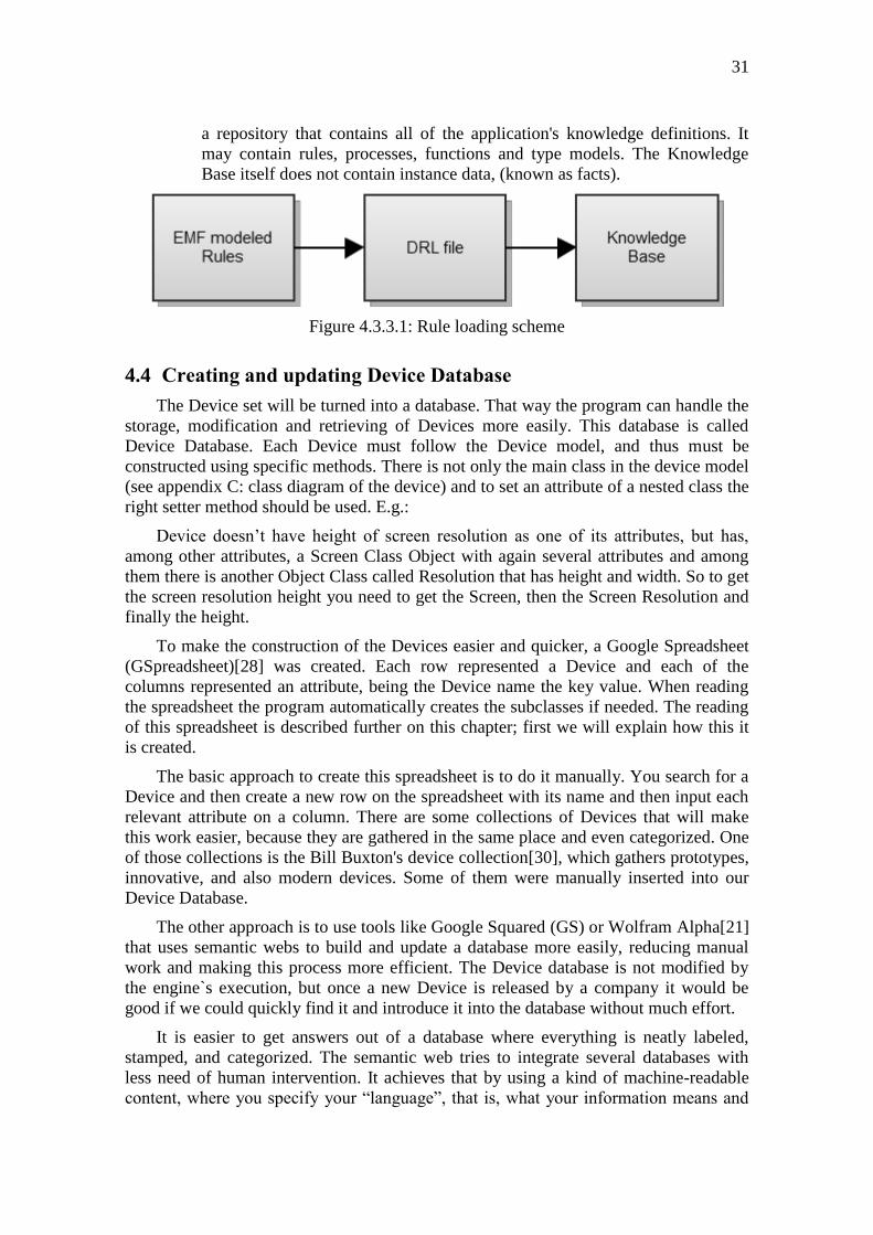
4.3.3 Rule Loading
To guarantee that the rules will be correctly interpreted by the engine three steps
must be followed:
1. EMF should be used to create a dynamic instance of a model that the end-user
will add, remove and modify the rules. Besides guiding the end-user of
restrictions of the rule model, it also validates the formed rules to indicate if
something is missing, like a rule without a condition.
2. The modeled rules are then read by the software and it automatically writes in a
Drools Rule Language file according to Drools‟s syntax and semantics. That
file has the „drl‟ extension and will be called DRL file from now on. Each
modeled rule is evaluated separately and if some of them don‟t follow the
model the ones that do will be written anyway, and a warning message is
shown to the user. This step is done in run-time and can be skipped by using
an existent DRL file. Later this file can be manually modified as any text file.
3. The third step is done entirely by Drools engine. It uses a Knowledge Builder
that reads the DRL file to create the knowledge base. The knowledge base is
Page 31
31
a repository that contains all of the application's knowledge definitions. It
may contain rules, processes, functions and type models. The Knowledge
Base itself does not contain instance data, (known as facts).
Figure 4.3.3.1: Rule loading scheme
4.4 Creating and updating Device Database
The Device set will be turned into a database. That way the program can handle the
storage, modification and retrieving of Devices more easily. This database is called
Device Database. Each Device must follow the Device model, and thus must be
constructed using specific methods. There is not only the main class in the device model
(see appendix C: class diagram of the device) and to set an attribute of a nested class the
right setter method should be used. E.g.:
Device doesn‟t have height of screen resolution as one of its attributes, but has,
among other attributes, a Screen Class Object with again several attributes and among
them there is another Object Class called Resolution that has height and width. So to get
the screen resolution height you need to get the Screen, then the Screen Resolution and
finally the height.
To make the construction of the Devices easier and quicker, a Google Spreadsheet
(GSpreadsheet)[28] was created. Each row represented a Device and each of the
columns represented an attribute, being the Device name the key value. When reading
the spreadsheet the program automatically creates the subclasses if needed. The reading
of this spreadsheet is described further on this chapter; first we will explain how this it
is created.
The basic approach to create this spreadsheet is to do it manually. You search for a
Device and then create a new row on the spreadsheet with its name and then input each
relevant attribute on a column. There are some collections of Devices that will make
this work easier, because they are gathered in the same place and even categorized. One
of those collections is the Bill Buxton's device collection[30], which gathers prototypes,
innovative, and also modern devices. Some of them were manually inserted into our
Device Database.
The other approach is to use tools like Google Squared (GS) or Wolfram Alpha[21]
that uses semantic webs to build and update a database more easily, reducing manual
work and making this process more efficient. The Device database is not modified by
the engine`s execution, but once a new Device is released by a company it would be
good if we could quickly find it and introduce it into the database without much effort.
It is easier to get answers out of a database where everything is neatly labeled,
stamped, and categorized. The semantic web tries to integrate several databases with
less need of human intervention. It achieves that by using a kind of machine-readable
content, where you specify your “language”, that is, what your information means and
Page 32
also translations between them[20]. Several small and big companies and interest
groups are researching and improving the current Semantic Web technologies[17].
A trial was made using GS to find several Devices and attributes2. We did not
create a new semantic, but used GS tool and its semantic to quickly create a spreadsheet
of Devices (row) and their attributes (columns). There is an option to export that
spreadsheet to a GSpreadsheet. Each Device had 21 attributes and 24 Devices were
easily added to the database. An example of a search can be seen in figure 4.4.1.
Figure 4.4.1: Google Squared smartphones search
Wolfram Alpha is another tool that does much effort in semantic webs, but cannot
be used to be a replacement for GS because it has a relatively small database. When
searching for “Device” it returns nothing. Even if it did, it wouldn`t update its
database as quickly as GS. Finally, assimilating the info from Wolfram Alpha would
be harder, since the output rarely is a spreadsheet.
Besides the tool to build the spreadsheet, once it‟s built it must be read by our
software and create the Device instance. This reading was made by using the
GSpreadsheet API[29], and each cell returned a string. Some manual work is
required, such as conversions of currencies (like Brazilian R$ to US$) and weights
(like ounce to pounds), the identification of different currencies and weights (dollar
appears as USD, $, US$, American dollar, etc.) and also some more restrict
formatting. E.g.:
For the attribute “Screen resolution” the format is “width x height” and the tool may
find a result like “4:3 ratio-1024px by 768px”. In those cases that cell needs to be
manually changed to “1024 x 768”.
Some techniques were applied after reading the cell to minimize that manual work
in order to set the attribute properly:
2 Unfortunately Google Squared was shut down as part of the phasing out of Google Labs on September
5, 2011, and the Semantic Web concerning the Devices is lost. The database and the spreadsheet of the
Devices is still used, but must be updated manually.
Page 33
33
• Ignore cell: the first thing we have to care about is what cells should be ignored.
This is applied to all cells and the most obvious cell to be ignored is an
empty cell. The other conditions to ignore cells are if its content is only “no”
or “none”. This happens because tools also explicit when an attribute is not
present. E.g.: the Device attribute “Video card” is “none”. Therefore this cell
can be ignored and no “Video card” will be set for that Device.
• Existent: if the attribute is a Boolean, it doesn‟t matter what is written, as long as
is not ignored. The software only wants to know if there is something in the
cell: if the cell is ignored the result is “false”, otherwise the result is “true”.
E.g.: a cell USB is “Three USB 2.0 ports”. That means that USB presence is
true.
• Consider only numerals: if the result should be a numeral value, it considers
only numerals and dots. If no numerals are found the cell will be ignored.
E.g.: A cell with “weight 7.4 ounces” can be read as “7.4”.
• Simple conversions: Converts string to real or integer numbers if needed, if a
real number should be an integer it is converted also. This is an
automatization that can be improved to more complex conversions as future
work.
• If several values are needed the software can read only one cell and split it in
substrings to apply techniques individually. E.g.: the string “4:3 ratio-1024px
by 768px” can be split by spaces and return four substrings: “4:3”, “ratio-
1024px”, “by” and “768px”. Then if we apply the technique above to
consider only numerals it would result in: “43”, “1024”, “768” and also an
empty string, as the “by“ substring doesn‟t have any numerals.
• Case insensitive: always when dealing with string attributes, upper case and
lower case characters are considered the same.
• Word matching: when the result should be a word and the string of the cell is
composed by several words it compares each word with the possible results.
That result is used if exactly one perfect match is found. E.g.: Let‟s say that
an Attribute called “Card Type” can be either “Audio” or “Video”. In these
cases cells with “audio on”, “High Audio Definition” and “Integrated audio”
would result in Card Type Audio.
• String similarity: this is used only if word matching fails to find a result. All the
spaces of our string are suppressed and each possible option will be
compared with the read string and will be used the option that has the lowest
Levenshtein Distance[27], which is the minimum amount of edits needed to
transform the option string into the read string. The edits are: insert, remove
or switch a letter (char). E.g.: “house” and “hostel” have distance 3.
Figure 4.4.2: Levenshtein distance from house to hostel
Page 34
4.5 Knowledge session
Knowledge Sessions are created from the Knowledge Base and they store and
execute the run-time data like facts and process instances respectively. The creation
of a session is a resource-intensive process. There are two types of Sessions:
A Stateful Knowledge Session is from where the process can be started, namely
the method fireAllRules(). They will run until the method dispose() is called.
It`s is possible to call iterative methods, like Insertion (to insert a new fact in
the session), Retraction (to remove a fact from the database) and Modify (to
update a fact). All those calls may cause re-firing of rules. Retractions may
fire a rule that has a condition of “non-existence” of a fact and Modify calls a
revaluation of all the rules of the active “Agenda-group” that has the updated
fact as a condition.
A Stateless Knowledge Session is used in relation to decision service-type
scenarios and encapsulates all the calls above. You cannot call fireAllRules()
nor the three interactive calls described above. The execute() method takes all
the facts as a parameter and do the other calls: instantiates a Stateful
Knowledge Session internally, insert all the facts, call fireAllRules() and
finally dispose() method.
Initially a Stateless Knowledge Session was used due to the lack of temporal events,
all of them happened at the same time. After some research of both sections‟
behaviors it was found that the Stateless section uses a Stateful one internally, so it
is not faster than the Stateful. The software of this work uses a Stateful Knowledge
Session because there are some things that will rarely change, like the rules and the
Devices (Devices are changed just when explicitly reloaded). It`s quicker to add and
remove the Scenario every time and maintain the session running than to re-create it
each time.
4.6 Interface
The Graphical User Interface (GUI) allows the end-user to interact with the program
and vice-versa. The software uses it to give feedback to the end-user, and the end-
user uses it to modify the Scenario and the database, as well as to execute the
engine. Java already has an Application programming interface (API) toolkit to
provide GUI called Swing[25]. One downside of Swing is that the visual result is
only possible at runtime. A GUI designer tool called visualswing4eclipse[19]
provides a Swing designer for Eclipse for Java developers. It allows the programmer
to generate the GUI visually with a WYSIWYG approach and auto-generates Swing
code based on the visual interface.
When the program is launched, the first thing that appears is a loading.
Figure 4.6.1: Loading window
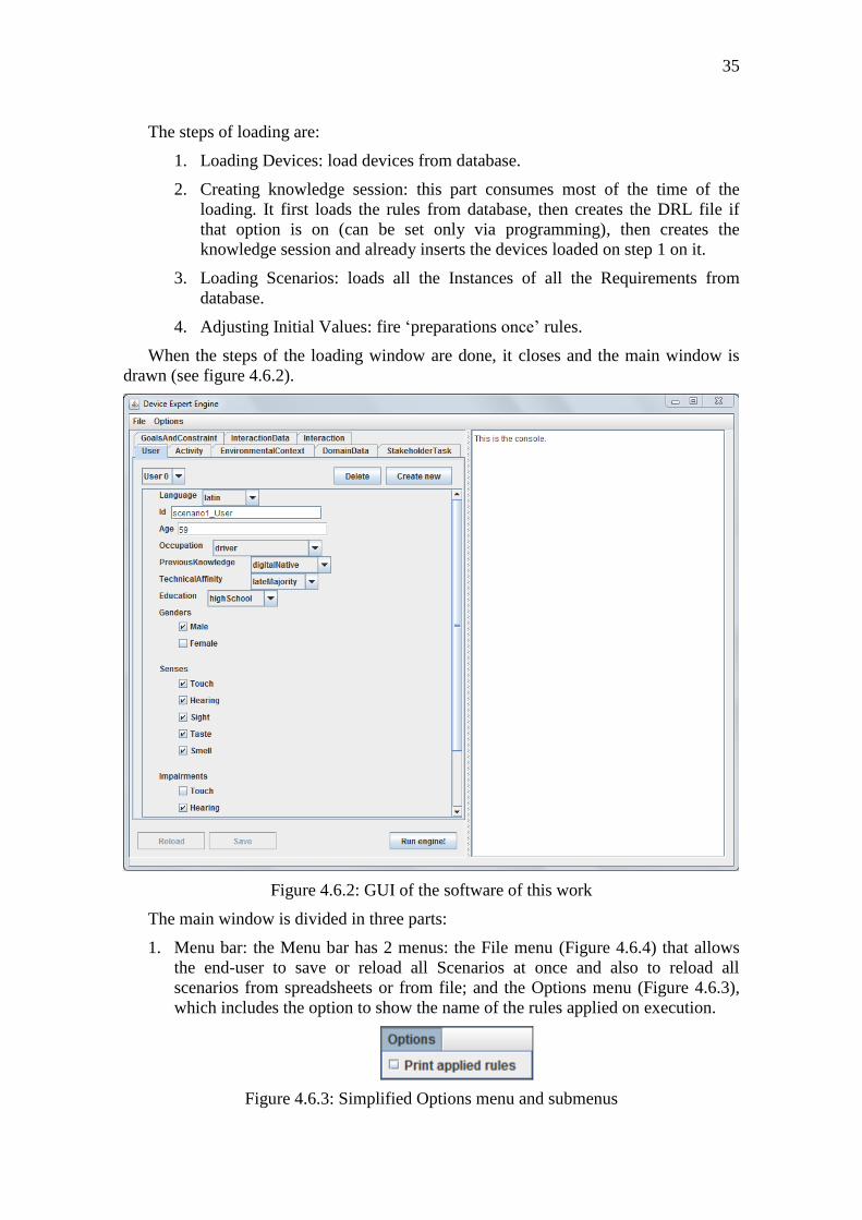
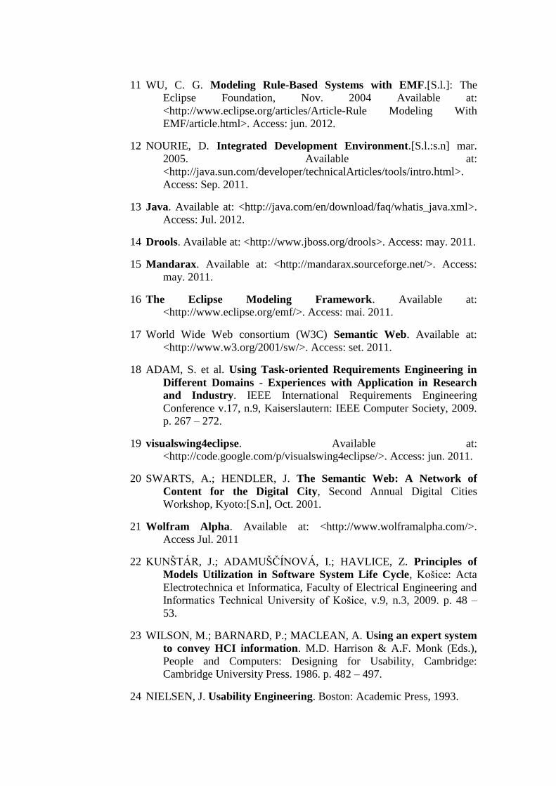
Page 35
35
The steps of loading are:
1. Loading Devices: load devices from database.
2. Creating knowledge session: this part consumes most of the time of the
loading. It first loads the rules from database, then creates the DRL file if
that option is on (can be set only via programming), then creates the
knowledge session and already inserts the devices loaded on step 1 on it.
3. Loading Scenarios: loads all the Instances of all the Requirements from
database.
4. Adjusting Initial Values: fire „preparations once‟ rules.
When the steps of the loading window are done, it closes and the main window is
drawn (see figure 4.6.2).
Figure 4.6.2: GUI of the software of this work
The main window is divided in three parts:
1. Menu bar: the Menu bar has 2 menus: the File menu (Figure 4.6.4) that allows
the end-user to save or reload all Scenarios at once and also to reload all
scenarios from spreadsheets or from file; and the Options menu (Figure 4.6.3),
which includes the option to show the name of the rules applied on execution.
Figure 4.6.3: Simplified Options menu and submenus
Page 36
Figure 4.6.4: Simplified File menu and submenus
2. Tabbed Panel: the Tabbed has one tab for each Requirement. Each tab has 3
main components:
a. Scroll panel: shows the Scenario and allows the end-user to modify it. It
is build based on the Requirement Models, so a modification on
the model will instantly modify the interface and, on the other
hand, using the interface is guarantee to follow the model. Each
class on the model will become a new label; ENUM (fixed set of
constants) Attributes will become a single “Combo Box” (a list of
attributes that you have to choose only one); Boolean attributes
become Check boxes; and every other Attribute will become a
text field. All Buttons can be seen in figure 4.6.5 below.
b. Special Buttons: they are the same for all tabs and are located around the
scroll panel. There are four data buttons, that are used for modify
the database. Their functions are: Delete a Target and remove it
from scenario and database; Create new empty Target and insert
it into the scenario; and Load and Save current Target from/to
database, if the Target has been modified. There is the Execute
engine! button which launches the engine (see figure 4.6.5).
Figure 4.6.5: GUI of the software of this work with device rank
Page 37
37
c. “Combo Box”: stores the instances of the Scenarios, showing each one
and allowing the end-user the switch between them. The selected
instance of a Requirement is the one that will be inserted on the
Knowledge Session when executing the engine.
Figure 4.6.6: Example of combo box in use, User 0 is selected
3. Text Panel: is the right half of the interface and shows the device rank, the name
of the rules applied, when this option is on (see figure 4.6.7), confirmation of
actions performed by the end-user, like pressing a Button, and also can be used
for debug. It can be used to warning and errors messages, although usually
dialogs have that purpose.
Figure 4.6.7: Example of device rank with applied rules
Page 38
There is another small interface component called Dialog. Dialogs are pop-up
windows that halt the program and ask for end-user action, they wait for
confirmation or choice. They are used to give options to the end-user (see figure
4.6.8 and to show warning and error messages (see figures 4.6.9 and 4.6.10). A
warn message alerts the end-user that something can cause problems in the future.
An error message is shown when a problem had already occurred.
Figure 4.6.8: Example of option dialog
Figure 4.6.9: Example of warning dialog
Figure 4.6.10: Example of error dialog
Page 39
39
5 PROGRAM EXECUTION
This chapter will be a brief description of the internal computations made on each
step of the software. There is the startup, the end-user actions, the execute engine
and the suitability rank. Those four steps are described below:
1. Startup: When running the software the first thing that it will do is to load the
engine, the Scenarios and the Interface. It creates a loading window (Figure
4.6.2) that inform the end-user an overview of what`s being made, because it can
take several seconds. The steps are:
a. Initialize engine: creates empty databases for each Target, store the getter
methods for them and also store the xmi file path.
b. Load Devices: create device database by loading them from file or from
GSpreadsheet. The Devices are loaded in a separate function from the
requirements because it may need internet access. If this step doesn‟t
work, the devices are loaded from file.
c. Create knowledge session: load the rules to create the Knowledge Base
and then create a Stateful Knowledge Session from it.
d. Loading Scenarios: each Target has a corresponding xmi file. In this step
the empty databases will be filled with the data loaded from a xmi file
using the xmi path file from step 1. In case of reloading the Scenario,
each database will be overwritten using the same path.
e. Adjusting initial Values: with the session created and the devices already
inserted, the engine will fire the “Preparation Once” rules.
f. Create interface: The last step is to close the loading window and create
the end-user interface (Figure 4.6.5).
2. End-user actions: In this step the end-user will modify his/her scenario, loading
and saving the requirements; may create new instances and change the options
(see Figure 4.6.4). When the scenario is done the Execute engine step may take
place.
3. Execute engine: When the end-user wants to know which Device is the most
suitable for the Scenario, he/she should press the „Execute Engine!‟ button.
Before the result is shown, a process chain is unleashed and the end-user cannot
see nor interact with it:
a. Takes current Scenario and pack it to Drools Engine: each requirement
has one active instance, which is the selected one. The software takes
Page 40
each selected instance and adds them to a list. This list is then sent to
Drools Engine.
b. Insert Scenario in the knowledge session: insert the list in the session,
storing the handlers necessary to remove the scenario later.
c. Reset suitability of the devices: all pros and cons are set to 0. The devices
don`t need to be re-inserted because only their suitability will change
during engine`s execution.
d. Fire “Preparation Rules”. Preparation rules are explained on session
4.3.1.
e. Fire “Main Rules”: Main rules are explained on session 4.3.1.
f. Retract Scenario: remove the Scenario from the knowledge session using
the handlers from step 2. Remember that Devices are not retracted.
4. Suitability rank: rank construction is detailed on session 3.2.1 Suitability. With
the rank built the solution is reached. The rank is then shown to the end-user
with the position of each Device, their pros and cons. The end-user may
continue to modify the scenario and execute the engine again, as the step goes
back to the “End-user actions”.
Figure 5.1: Program execution scheme
Page 41
41
CONCLUSION
The basic steps of the work done were:
1. MCE and state of art
2. Identification of the relevant Requirements of the Model TORE.
3. Modeling of Device and all the Requirements on Eclipse.
4. Make it possible load and save the Scenarios.
5. Define a Scenario and rules that will be applied on it.
6. Choose Drools as our ES engine.
7. Model the rules as an interface to Drools.
8. Update Devices from a spreadsheet. This spreadsheet was built using GS.
9. Create GUI using visualswing4eclipse.
10. Able end-user to modify/expand the Requirement database (remove, change or
add).
After all this steps the software has a database of Devices and allows end-users to
specify and expand Scenarios so the software can build a Device rank from it. The
best devices for the scenarios tested are similar, if not the same, as the ones chosen
by experts. The tool of this work fulfills its objective.
One issue is that sometimes the Device configuration is being chosen and not the
Device itself. The same desktop can have different screen sizes or resolutions and
may or may not have a keyboard or mouse plugged. Unfortunately all this is treated
as a solid block by definition. If we introduced a peripheral in our device database, it
would be treated as a singleton and therefore will have few characteristics (and
requirements matches) and even if it did reach a good ranking, another device would
be necessary for it to work.
An appropriate solution for peripherals would be to look at the
requirements/attributes of the Devices and if one of them is an additional Device, we
would have to check if there are money, slots, etc. enough to fulfill it. If so, we
could set the pros and cons of both devices against each other. Even the combination
of several Devices trying to heighten its ranking would be possible. It was not done
because this issue was identified only in the end phase of the software, and the
potential gain in suitability does not compensate the reformulation, remodeling and
recoding required.
Page 42
As future work more rules should be created to explore the attributes of the Targets
better. Right now a not all the attributes influences the final rank and if this subset is
not specified then is expected that the final rank has many ties. Ties can be avoided
by improving the comparison functions between two devices and also by weighting
the rules, which would require more expert knowledge acquisition.
Some possible features for this software would be a better interface, maybe even a
rule editor via interface or also reducing even more the manual work of building the
Devices by making an automatic converter between currencies and weights. A
substitute to GS would be required to efficiently update the Device database,
otherwise manual update will be needed.
Page 43
43
REFERENCES
1 WAGNER, P. Working Paper of COST Action 356, WG 3 meeting,
Task 3.2, Torino: Oct. 2007.
2 MUNDA, G. “Measuring Sustainability”: A Multi-Criterion
Framework. Journal of Environment, Development and
Sustainability, Barcelona, v.7, n.1: Springer Netherlands, 2003.
3 BEINAT, E.; NIJKAMP, P. Multi-criteria analysis for land-use
management. Dordrecht: Kluver Academic Publishers, 1998.
4 TIMMERMANS, H. J. P.; JEIJDEN, R. E. C. M. van der. Uncovering
spatial decision-making processes: a decision net approach
applied to recreation choice behavior. Tijdschrift voor
Economische en Sociale Geografie, v.78, n.4,[S.l.]: Royal Dutch
Geographical Society KNAG, Sep. 1987. p. 297 – 304.
5 ADiWa. Available at: <http://www.adiwa.net>. Access: jun. 2012.
6 WITLOX, F. MATISSE - a relational expert system for industrial site
selection. Expert Systems with Applications Journal, Gent:
Pergamon, 2003.
7 RESHMIDEVI, T.V.; ELDHO, T.I.; JANA, R. A GIS-integrated fuzzy
rule-based inference system for land suitability evaluation in
agricultural watersheds. Expert Systems with Applications Journal,
v. 101, n. 1–2,[S.l.]: Elsevier, jun. 2009. p. 101 – 109.
8 LAUKKANEN, S.; KANGAS, A.; KANGAS, J. Applying voting
theory in natural resource management - a case of multiple-
criteria group decision support. Journal of Environmental
Management, v. 64, n. 2, set. 2001. p. 127-137. Available at:
<http://www.sciencedirect.com/science/article/pii/S03014797019051
10>. Access: jun. 2012.
9 FRASER, N. M.; HAUGE, J. W. Multicriteria approval: application
of approval voting concepts to MCDM problems. Journal of
Multi-Criteria Decision Analysis, Ontario, v.7, n.5: John Wiley &
Sons, 1998.
10 OLDFIELD, P. Domain Modelling. [S.l.] : Appropriate Process Group,
2002
Page 44
11 WU, C. G. Modeling Rule-Based Systems with EMF.[S.l.]: The
Eclipse Foundation, Nov. 2004 Available at:
<http://www.eclipse.org/articles/Article-Rule Modeling With
EMF/article.html>. Access: jun. 2012.
12 NOURIE, D. Integrated Development Environment.[S.l.:s.n] mar.
2005. Available at:
<http://java.sun.com/developer/technicalArticles/tools/intro.html>.
Access: Sep. 2011.
13 Java. Available at: <http://java.com/en/download/faq/whatis_java.xml>.
Access: Jul. 2012.
14 Drools. Available at: <http://www.jboss.org/drools>. Access: may. 2011.
15 Mandarax. Available at: <http://mandarax.sourceforge.net/>. Access:
may. 2011.
16 The Eclipse Modeling Framework. Available at:
<http://www.eclipse.org/emf/>. Access: mai. 2011.
17 World Wide Web consortium (W3C) Semantic Web. Available at:
<http://www.w3.org/2001/sw/>. Access: set. 2011.
18 ADAM, S. et al. Using Task-oriented Requirements Engineering in
Different Domains - Experiences with Application in Research
and Industry. IEEE International Requirements Engineering
Conference v.17, n.9, Kaiserslautern: IEEE Computer Society, 2009.
p. 267 – 272.
19 visualswing4eclipse. Available at:
<http://code.google.com/p/visualswing4eclipse/>. Access: jun. 2011.
20 SWARTS, A.; HENDLER, J. The Semantic Web: A Network of
Content for the Digital City, Second Annual Digital Cities
Workshop, Kyoto:[S.n], Oct. 2001.
21 Wolfram Alpha. Available at: <http://www.wolframalpha.com/>.
Access Jul. 2011
22 KUNŠTÁR, J.; ADAMUŠČÍNOVÁ, I.; HAVLICE, Z. Principles of
Models Utilization in Software System Life Cycle, Košice: Acta
Electrotechnica et Informatica, Faculty of Electrical Engineering and
Informatics Technical University of Košice, v.9, n.3, 2009. p. 48 –
53.
23 WILSON, M.; BARNARD, P.; MACLEAN, A. Using an expert system
to convey HCI information. M.D. Harrison & A.F. Monk (Eds.),
People and Computers: Designing for Usability, Cambridge:
Cambridge University Press. 1986. p. 482 – 497.
24 NIELSEN, J. Usability Engineering. Boston: Academic Press, 1993.
Page 45
45
25 Swing (Java). Available at: <http://en.wikipedia.org/wiki/Swing_(Java)>.
Access: mail. 2011.
26 java.util Class Collections sort. Available at:
<http://download.oracle.com/javase/1.4.2/docs/api/java/util/Collectio
ns.html#sort(java.util.List, java.util.Comparator)>. Access: may.
2011.
27 Levenshtein distance. Available at:
<http://en.wikipedia.org/wiki/Levenshtein_distance>. Access: Jul.
2011.
28 Google Spreadsheets. Available at: <http://www.google.com/google-d-
s/spreadsheets/>. Access: jun. 2011.
29 Google Spreadsheets API. Available at:
<https://developers.google.com/google-apps/spreadsheets/>. Access:
jun. 2012.
30 Buxton Collection. Available at: <http://research.microsoft.com/en-
us/um/people/bibuxton/buxtoncollection/>. Access: jan. 2012.
31 String Hashcode. Available at:
<http://docs.oracle.com/javase/1.4.2/docs/api/java/lang/String.html#h
ashCode>. Access: Dec. 2011.
32 RUSSEL, S. J.; NORVIG, P. Artificial Intelligence: A Modern
Approach. Chapter 1.3: The History of Artificial Intelligence, New
Jersey: Prentice Hall, 2003.
33 HICKS, R. C. The no inference engine theory – Performing conflict
resolution during development, Decision Support Systems, Volume
43, Issue 2, Laredo: Elsevier, may. 2007 p. 435 – 444.
34 GROSAN, C.; ABRAHAM, A. Rule-Based Expert Systems. In:
Intelligent Systems: A Modern Approach. [S.l]: Springer, 2011 p.
149 – 185.
Page 46
ATTACHMENT DROOLS USERS AND SOFTWARE
OFFERING DROOLS INTEGRATION
Users:
Innovision
DeCare Systems
Kiala
Betfair
actis.bsp
Sabre Holdings
Auster
German Aerospace Center
Chooze-it
EAS EA Evaluator
Advanced Engineering Solution (AES)
Integrators:
JBoss (jBPM, Seam, ESB, MicroContainer)
Zementis ADAPA
Mule
Sidonis
Service Mix
Pogamut
Intalio
Cisco Active Network Abstraction
Source: http://www.jboss.org/drools/sightings
Page 47
47
APPENDIX A: TABLE OF EVALUATED EXPERT
SYSTEM ENGINES
Name Area/Technique Advantages Disadvantages Language
Sweet Rules Tools for Semantic
Web Rules and
Ontologies, including
Translation,
Inferencing, Analysis,
and Authoring.
Has prioritized
conflict handling,
seems to be
flexible, has a
discussion forum
It‟s still a work in
progress, with
several minor
bugs
Java
SHOP Ordered task
decomposition, which
is a type of
Hierarchical Task
Network (HTN)
planning. The tasks are
broken into subtasks
until primitives are
reached.
Can do mixed
symbolic/numeric
conditions
Weak
documentation,
uses a list-like
syntax, that can
be hard to debug
Java, Lisp
Pellet Web Ontology
Language (OWL 2)
reasoner. Provides
standard and cutting-
edge reasoning
services for OWL
ontologies. It
incorporates
optimizations for
nominals, conjunctive
query answering, and
incremental reasoning.
The interface used
is the same as
Jena, support
punning (ifAll,
ifAny, etc.),
comes with
several simple
examples, so it
seems to be easy
to learn. Rules are
not verbose.
Axioms (facts)
about individual
equality and
difference must
be about named
individuals.
Java
OpenRules Full-scale Business
Rules Management
System (BRMS).
Easy to use (rules
are made via
spreadsheets),
multi-user
environment
Non-rete, it seems
that it‟s not a
reasoner, and it
has a commercial
version that is the
focus
Excel +
Java
Mandarax Backward chaining
(using prova). It
include unification
Algorithms and
selection policy
can be
The computation
is slower due to
some emphasis on
Java
Page 48
algorithm, loop
checking algorithm.
configured.
There‟s an eclipse
plugin for
inserting the
rules. There is an
interface.
reducing the
memory usage
JTP Backward-chaining
reasoner
Uses a set logic,
using
subPropertyOf
and subclassOf
Has no interface,
the end-use would
have to code to
interact with it or
it would have to
be embed into
something else.
Java
JLisa Lisa: Rete + Clips
(lisp)
Can use the
features of Lisp
No
documentation,
will have to look
at Lisa
documentation
(which is good);
uses a different
order of operands,
which is
unintuitive
Java, Lisp
JEOPS Forward chaining,
first-order production
rules
Rules are very
clear; while still
running, keeps a
base of previous
calculations
Lack of
abstraction of the
rules, they are
also quite
verbose.
Java
CLIPS Basic rule-based
engine
Simple, fast &
“efficient”. There
are some
suggested tweaks
to include Rete or
Bayesian
network.
Restrict. Has to
implement one
fixed rule per
device. The result
doesn‟t have any
degree of fitness.
C
d3Web Medical diagnosis,
documentation, and
therapy. Similar to
CLIPS with Rete
Algorithm. Uses more
complex techniques,
such as decision trees,
(heuristic) rules, and
set-covering models.
Returns a list of
possibilities,
suggested and/or
refused.
Complexity may
not be the answer,
and the questions
need to be quite
straightforward.
Java
EGanges Law/quality control.
Uses
Ishikawa_diagram.
You set the nodes to
yes/no/uncertain that
you know. You can
User can answer
or not a node,
independent from
order, If there‟s
inconsistencies
the expert system
This is often used
when you know
the objective and
wants to know if
is valid or not.
We‟ll have to
make multiple
Java
Page 49
49
follow the flow or not. warns you. objectives. The
answer doesn‟t
have any degree
of fitness.
Jena2 There are two Internal
rule engines: one is
forward chaining
RETE engine and the
other is a tabled
datalog engine
Broad and Broad
and solid
documentation
The focus is on
the Framework
and queries, the
rule engine is not
that developed
Java
Apache
OFBiz
Uses logic
programming
languages to combine
queries and facts
New way of
thinking
Adding an axiom
is quite
complicated, and
logic programing
is unusual
Logikus
(Prolog)
InfoSapient Business processes,
uses fuzzy systems
Rules are
externalized from
the application
and database, they
are easy to change
Would have to
halt the fuzzy
method before
completion and
analyze the partial
result so we can
have a list of
products instead
of only the best
one. Doesn‟t
support ifAny,
ifAll, or
ifNoneOf.
Java
OpenExpert It‟s a toy software, not
for company use
Very simple and
functional
It‟s a toy
software, have
weak
documentation,
only one final
result, still a work
in progress
PHP,
MySQL
Euler Backward-chaining
with Euler path
detection, it is used for
academic purposes
only. It‟s somehow
similar to CLIPS
Easy to add facts,
available in
several languages
Syntax is a little
confusing and
may be hard to
use, used for
academic
purposes only
Java, C#,
Python,
JavaScript
or Prolog
Drools Rules, Workflow and
Event Processing
Broad and
complete
documentation,
has side by side
rule flow
authoring with
rules, event
processing, etc.
May be too
big/complex.
Java
Page 50
APPENDIX B: CLASS DIAGRAMS OF THE
REQUIREMENTS
Activity:
Domain Data:
Page 51
51
Environmental Context:
Goals and Constraints:
Page 52
Interaction Data:
Interaction:
Page 53
53
Stakeholder Tasks:
User:
Page 54
APPENDIX C: CLASS DIAGRAM OF THE DEVICE