Expert system for seismic vulnerability assessment of masonry structures
S. ChurilovUniversity Ss. Cyril and Methodius, Faculty of Civil Engineering, Skopje, Macedonia
ABSTRACT: Possible method for seismic vulnerability assessment of masonry structures with special attentionto low-rise residential structures in Macedonia is proposed in this paper. For this purpose, special calculationtool which contains specific knowledge for masonry structures derived by numerical calculations and analysesis developed. The aim of this assessment tool is to be simple for application even for personnel with slight or noexperience in behaviour of masonry structures under seismic action, so it could be developed as a serious systemfor fast and precise assessment of the condition of many structures in a wide region. In this paper, a numericalmodel for calculation of the bearing capacity of the structure based on the discrete element method is suggested,so that it is first application of this relatively new numerical technique for calculation of masonry in Macedonia.A method for creation of the knowledge base for an Expert System suggested by the given methodology ispresented. Also, results from the application of this methodology are applied on a real structure.
1 INTRODUCTION
The aim of this paper is development of a ExpertSystem which will enable fast and precise seismicvulnerability assessment of existing masonry struc-tures and will provide data for predicting the damageof masonry structures under influence of earthquakeswith given intensity. The Expert System is a tool foraccurate seismic vulnerability assessment of masonrystructures based on a numerical analysis model whichincludes nonlinear behaviour of masonry and takesinto account nonlinear bearing reserves of masonry.Due to the complexity and the different geometricand material parameters, the Expert System containsseveral databases that include capacity and seismicdemands for the most common layouts of low-rise res-idential masonry buildings, typical for Macedonia andBalkan region. For the purpose of development of anExpert System, Exsys CORVID shell was used. (ExsysCORVID 2004).
2 THE BASICS OF EXPERT SYSTEMS
Expert System is a computer program which emulatesmutual conversation of one human to another, expertin specific domain, who asks for advice or recom-mendation from the human expert in order to solveparticular problems. This new approach is promising,especially in structural analysis of masonry structures,where often one can make a decision which is notbased on analytical models, but only on experienceand intuition of the engineer involved.
Many expert systems are not complex or difficult tobuild. In a very simple case, consider a tree diagram onpaper describing how to solve a problem. By making
a selection at each branch point, the tree diagram canhelp someone make a decision. In a sense, it is a verysimple expert system.This type of tree structured logiccan easily be converted to a computerized system thatis easier to use, faster and automated. More elabo-rate systems may include confidence factors allowingseveral possible solutions to be selected with differentdegrees of confidence.
Expert systems can explain why data is neededand how conclusions were reached. A system may behighly interactive (directly asking the user questions)or embedded where all input comes from another pro-gram. The range of problems that can be handled byexpert systems is vast.
Expert systems can be developed with Expert Sys-tem Shells. An expert system shell is a software pro-gramming environment which enables the construc-tion of expert or knowledge based systems. Expertsystems software can be developed for any problemthat involves a selection from among a definable groupof choices where the decision is based on logical steps.Any area where a person or group has special expertiseneeded by others is a possible area for an expert system.Expert systems can help automate anything from com-plex regulations to aiding customers in selecting fromamong a group of products, or diagnosing equipmentproblems.
Traditionally expert system development has beena major expense both in time and money. Gettingeven a single system built was a big project. Thecost of system development prohibited building expertsystems on more than a few projects. The key to imple-menting expert systems widely, effectively and at lowcost is to have easy-to-use expert system developmenttools readily available to the experts. As more poweris needed for certain applications, higher level tools
1449
can be used with advanced features to give you com-plete control over the inference engine, modularizationof the knowledge base, flow of execution, the userinterface and integration with other programs.
Expert systems have several advantages and dis-advantages. Among the advantages, the following aremost important:
– Permanence – Expert systems do not forget, buthuman experts may
– Reproducibility – Many copies of an expert systemcan be made, but training new human experts istime-consuming and expensive
– Efficiency – can increase throughput and decreasepersonnel costs. Although expert systems areexpensive to build and maintain, they are inex-pensive to operate. Development and maintenancecosts can be spread over many users. The overallcost can be quite reasonable when compared toexpensive and scarce human experts.
– Consistency – With expert systems similar trans-actions handled in the same way. The systemwill make comparable recommendations for likesituations.
– Humans are influenced by recency effects (mostrecent information having a disproportionateimpact on judgment) primacy effects (early infor-mation dominates the judgment).
– Documentation – An expert system can providepermanent documentation of the decision process
– Completeness – An expert system can review allthe transactions, a human expert can only review asample
The most important disadvantages of expert sys-tems are:
– Common sense – In addition to a great deal oftechnical knowledge, human experts have commonsense. It is not yet known how to give expert systemscommon sense.
– Creativity – Human experts can respond creativelyto unusual situations, expert systems cannot.
– Learning – Human experts automatically adaptto changing environments; expert systems mustbe explicitly updated. Case-based reasoning andneural networks are methods that can incorporatelearning.
– Sensory Experience – Human experts have avail-able to them a wide range of sensory experience;expert systems are currently dependent on sym-bolic input.
– Degradation – Expert systems are not good atrecognizing when no answer exists or when theproblem is outside their area of expertise.
When the rule set for an expert system is written, theknowledge of humans is observed. Video tapes, inter-views, protocol, and other techniques are used to tryto capture the thought process of experts. A problemwith expert systems is writing the rules themselves.Thought processes that are highly rule-oriented areeasier to write than ones that rely more on creativity or
intuition. Another problem is that often experts them-selves disagree. Different experts might take differentcourses of action or go through different thought pro-cesses when given the same problem to solve. Thusthere is disagreement in the professional communityabout the validity of expert systems.
Expert systems are improving as technologyadvances. In the past, expert systems have receivedcriticism and some negative publicity because of thefailures that were highly publicized. Unfortunately, thesuccesses are less publicized, because companies wantto maintain their competitive edge. It is important forcompanies to remember, however, that humans shouldmake the final decision, and not the computer. Humansstill have the insight and intuition that computers areunable to possess–for now, anyway.
3 METHODOLOGY FOR DEVELOPMENT OFEXPERT SYSTEM KNOWLEDGE BASE
Figure 1 presents the suggested methodology fordevelopment of Expert system knowledge base forseismic vulnerability assessment of masonry struc-tures that corresponds to the core of the system andwithout it the expert system would not operate. It con-tains three major branches which determine Capacity,Demand and Damage of the building.
Seismic vulnerability assessment of a structure isdetermined by a seismic capacity coefficient, definedas a ratio of Capacity to Demand. The limit valueof seismic capacity coefficient is 1.0 and the valuesgreater than the limit value define a vulnerable struc-ture which cannot withstand and transfer the seismicloads.
All needed data is stored in databases and commu-nication between the expert system and the databasesis obtained by using the expert system shell optionsfor connecting the rules with the data.
3.1 Capacity of the building
In order to determine the capacity of a building toresist seismic action, in earthquake engineering it ispresented by a capacity curve. To express the capacityof any structure, several assumptions should be made:
– Regular layout in ground and elevation plan. It sup-poses continuous shear walls over the height of thebuilding, so one can assume failure mechanism inthe ground floor.
– Floor slabs are assumed as rigid horizontaldiaphragms, while masses are concentrated at thefloor slab levels.
– Stiffness of out-of-plane walls is not taken into con-sideration; it is assumed that they transfer the loadsin their own plane only.
– Torsion effects are not included into calculations.
According to the previous assumptions, one canmake a conclusion that it is necessary to determinethe Capacity Curve of the ground floor only, since the
1450
Figure 1. Methodology for development of Expert system knowledge base.
rest of the floors behave in linear elastic manner. TheFailure mechanism of the ground floor is presented inFigure 2.
In order to calculate the capacity curve of the groundfloor it is assumed that floor slabs act as rigid hori-zontal diaphragms which transfer the horizontal loadscaused by earthquake actions onto the walls.
This methodology suggests numerical calculationof capacity curves by discrete element method andapplication of the software UDEC (UDEC, 2005).Hence, to obtain the capacity curves database whichis a component of the Expert system, it is necessaryto take into consideration different wall geometries,materials and different vertical loads. According tothis, it is required to perform numerical analysis forall possible combinations of wall data and loads andto create the knowledge database.
3.2 Seismic demand of the building
For the purpose of seismic vulnerability assessment ofa masonry building, one should determine the secondkey element, namely seismic demand. This methodol-ogy proposes calculation of the seismic demand by 3different techniques that prescribe the maximal hori-zontal force which should be resisted by the masonrystructure:
– Seismic design force according to Macedonianregulations for Seismic design of structures;
Figure 2. Failure mechanism of the ground floor.
– Dynamic analysis (seismic force calculated bytime-history analysis); and
– Capacity spectrum method.
The knowledge base of the Expert system allocatestabular data for equivalent horizontal seismic forces in
1451
dependence on soil conditions and earthquake inten-sity according to MCS.Also, it is supposed to generateseismic demand database which will contain the totalseismic force calculated as base shear reactions forspecific earthquake records and the adopted groundplans. As typical earthquake records El Centro (1940),Petrovac (1979) and Bitola (1994) earthquake recordsare used.
Numerical calculations are performed by the pro-gram Robot Millennium (Robot Millennium User’sManual, 2007) by applying linear dynamic time-history analysis. On the other hand, the Capacityspectrum method as a technique for seismic evalua-tion is not included in the expert system, but someother calculation tools like M-DESIGN use it. In thispaper a comparison of the results obtained by the sug-gested methodology and the program M-DESIGN ispresented.
4 APPLICATION OF THE SUGGESTEDMETHODOLOGY TO A TYPICALBUILDING IN MACEDONIA
The suggested methodology for development of theExpert system knowledge base and the suggestedmethods to obtain the capacity of the building andthe seismic demand are applied to a masonry struc-ture characteristic for the period from the beginningof 20th century in urban areas in Macedonia with anassumed earthquake scenario, i.e. seismic action.
The building under investigation is a typical struc-ture for the wider surrounding of the city of Gevgelija,built in 1928.The structure has basement, ground floorand one floor, so it is classified as low-rise building.Total building area is 240 m2, while available net areais 183.65 m2.The building has suffered moderate dam-age after Gevgelija earthquake on December 21, 1990with magnitude of 5.6 and intensity according to MCSVII-VIII. This earthquake has caused damage on thestructural systems of approximately 1,120 buildings inthe surrounding area.
Figure 3 presents the layout and geometry data ofthe ground floor of the building under consideration.The footings and the basement walls are made formlimestone and lime mortar. The walls on the first floorare constructed from solid clay bricks and lime mortar.Two partition walls on the first floor are made fromadobe bricks in wooden “bondruk” system. The floorslabs are made from timber beams simply supportedon the masonry walls. The floors in the ground floorare concrete with timber flooring and on the first floorwith parquet.
4.1 Capacity curve and seismic demand of thebuilding
After performing numerical calculations by the dis-crete element method and the software UDEC, thecapacity curves for all individual ground floor wallsare obtained. Since the walls which spread with their
Figure 3. Geometry data for the ground floor of the examplebuilding.
Figure 4. Capacity curves in X direction.
planes in X direction define the weaker direction ofthe building, only ground floor walls in direction X aretaken into account. Figure 4 shows the capacity curvesof the individual ground floor walls and the total capac-ity curve of the ground floor which is derived by simplesuperposition of the capacities of individual walls.
In order to obtain the ultimate values for the totalseismic force calculated from real earthquake records,a linear dynamic time-history analysis by finite ele-ment method is performed. The calculated period offree un-damped vibrations isT1 = 0.103 sec.The max-imal accelerations of the used earthquake records arescaled from 0.1g to 1.0 g.
Figure 5 presents a comparison diagram of thebuilding capacity and seismic demand for the seis-mic force obtained by different analysis techniquesand earthquake records. From the obtained resultsit is obvious that the building has sufficient capac-ity compared to the total seismic force calculated byMacedonian regulations, as well as by time-historyanalysis with un-scaled earthquake accelerations of ElCentro (0.3 g), Petrovac (0.4 g) and Bitola (0.23 g).
If the capacity of the building is expressed by thevalue of the force that determines the beginning of the
1452
Figure 5. Comparison diagram of the Capacity and theseismic Demand for the inspected building.
Table 1. Seismic capacity coefficient rc.
El Centro Petrovac BitolaIntensity MKS (kN) (kN) (kN)
0.1 g 1.46 3.69 5.98 3.370.2 g 1.46 1.84 2.99 1.680.3 g 1.46 1.23 1.99 1.120.4 g 1.46 0.92 1.50 0.840.5 g 1.46 0.74 1.20 0.670.6 g 1.46 0.61 1.00 0.560.7 g 1.46 0.53 0.85 0.480.8 g 1.46 0.46 0.75 0.420.9 g 1.46 0.41 0.66 0.371.0 g 1.46 0.37 0.6 0.34
nonlinear range (C), for X-direction ∼ 800 kN, and theseismic demand (D), one can obtain the value for theseismic capacity coefficient (rc). The following tablesummarizes the values for the seismic capacity coeffi-cient obtained by calculations of the ratio of Capacityover Demand.
Until the value for the seismic capacity coefficientis greater than 1.0, the structure is assessed as withsufficient vulnerability and has strength to withstandthe seismic forces. According to this, the limit valuesfor different earthquake intensities are denoted in bold.From the aforementioned, one can make a conclusionthat the building will suffer some structural damageunder El Centro 0.3g, but it will survive total collapseof the structure. The same result applies for the othertwo earthquakes Petrovac (0.4 g) and Bitola (0.23 g).
For validation of the suggested methodology forseismic vulnerability assessment of masonry struc-tures used in the presented Expert system, a Capacityspectrum method was used. Therefore, program M-DESIGN was used to calculate the structure behavioraccording to capacity spectrum method. As input datathe program uses the same capacity curves for the indi-vidual walls. In order to calculate the seismic load,elastic spectra definition as proposed in Eurocode 8
Table 2. Calculation of the performance point.
Result Unit Values
Spectral displacement m 0.00037Spectral acceleration m/s2 0.7411st period of vibration s 0.141
Figure 6. Calculation of the performance point withM-DESIGN program.
was applied. The calculation of the Performance pointfor the example building as defined in the capacityspectrum method is presented in Figure 6.
Table 2 summarizes the position of the Performancepoint and calculated period of free un-damped vibra-tions of the building. The conclusions obtained withM-DESIGN and Capacity spectrum method are listedas follows:
Ultimate limit state results:
– Bearing capacity of the building is satisfied– Seismic actions do not cause structural damage on
the building– Expected Damage grade according to EMS98 is I– Ultimate limit state is proved
Ultimate serviceability state results:
– Maximal displacement on wall 5 is 0.039 cm– Calculated floor displacement is 0.039 cm × 0.4 =
0.016 cm– Allowable floor displacement is 0.0075 cm ×
245 cm = 1.838 cm– 0.016 cm < 1.838 cm
The results obtained by using the Capacity spec-trum method are close to the results obtained by thesuggested methodology in the Expert system. The sta-bility of the structure is proved and according to thesuggested concept it has sufficient stability with occur-rence of no structural damage. This is also proved byM-DESIGN where the structure is classified with Idamage grade according to EMS 98.
1453
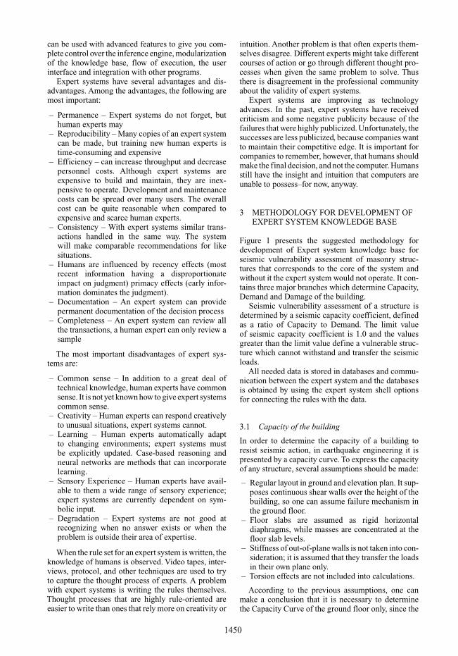
4.2 Screen shots of the developed Expert system
REFERENCES
Bicanic, N. et al. 2002. Discontinuous Modelling of Struc-tural Masonry. Mang H.A. et al (eds),WCCMV, FifthWorldCongress on Computational Mechanics, Vienna, Austria,July 7–12.
Butenweg, C. & Mistler, M. 2006. Seismic Resistance ofUnreinforced Masonry Buildings. The Fifth InternationalConference on Engineering Computational Technology,Las Palmas de Gran Canaria, 12–15 September.
Churilov S. 2007. Expert System for Seismic VulnerabilityAssessment of Masonry Structures. MSc thesis, Uni-versity “Sts. Cyril and Methodius”, Faculty of CivilEngineering, Skopje, Macedonia.
Dumova-Jovanoska E. & Denkovska L. 1995. Classifi-cation of Individual Unreinforced Masonry BuildingsConsidering Their Seismic Vulnerability. Developmentsin Computer Aided Design and Modelling for Struc-tural Engineering, Civil-Comp Press, Edinburgh, UK, pp.279–284.
Gramatikov K. 2006. WP7: Experimental Analysis, Reporton Testing of Bricks and Lime Mortar for Mustafa PashaMosque Model, PROHITECH Project, Sixth FrameworkProgramme, INCO-CT-2004-509119.
Guggisberg, R. & Thürlimann, B. 1987. Experimental deter-mination of masonry strength parameters. Report No.7502-5, Institute of Structural Engineering, Zürich.
Jovanovski M. & Josifovski J. 2006.WP 7: LaboratoryTestingon the Intact Parts of Stone Used in Construction of LargeScale Model For “Mustafa Pasha Mosque” in Skopje,Testing Report, PROHITECH Project, Sixth FrameworkProgramme, INCO-CT-2004-509119.
Lemos, J.V. 2004. Modelling Stone Masonry Dynamics with3DEC. Konietzky (eds): 1st International UDEC/3DECSymposium: Numerical modelling of Discrete Materials inGeotechnical Engineering, Civil Engineering and EarthSciences, Bochum, Germany, 29 September – 1 October,pp. 7–13.
Lourenço, P.B. 1996. Computational Strategies for MasonryStructures, Ph.D. Dissertation, Delft University of Tech-nology, Delft, Netherlands.
Lourenço, P.B. Experimental and Numerical Issues in theModelling Of the Mechanical Behaviour of Masonry.In P. Roca et al. (eds), Structural Analysis of HistoricalConstructions II. CIMNE, Barcelona, pp. 57–91.
Meskouris, K. et al. 2004. Seismic Behaviour of HistoricMasonry Buildings. 7th National Congress on Mechanicsof HSTAM, Chania, Crete, Greece.
Oliveira, D.V.C. 2003. Experimental and numerical analysisof blocky masonry structures under cyclic loading. Escolade Engenharia, Universidade do Minho, Portugal.
Orduña A. 2003. Seismic Assessment of Ancient MasonryStructures by Rigid Blocks Limit Analysis. Ph.D. Dis-sertation, University of Minho, Department of CivilEngineering, Guimarães, Portugal, November.
Priya et al. 2007. Some Case Studies on Probabilistic Fail-ureAnalysis of Unreinforced Brick Masonry Structures inIndia against Earthquake. Journal of the British MasonrySociety, Masonry International vol. 20. No. 1, pp. 35–54.
Ramos, L.F. 2002. Análise experimental e numérica de estru-turas históricas de alvenaria. MSc Thesis, Universidadedo Minho, Guimarães, Portugal.
Roca, P. et al. 2001. Mechanical response of dry jointmasonry. G. Arun and N. Seçkin (eds): 2nd Interna-tional Congress on Studies in Ancient Structures, YildizTechnical University, Istanbul, pp. 571–579.
UDEC – Universal Distinct Element Code 2005. User’sGuide, Itasca Consulting Group, Inc., Minnesota, USA.