Experts Experts in Torque in Torque-Tension Tension Testing Equipment! Testing Equipment! RS Technologies designs and manufactures a complete line of threaded fastener torque-tension test systems. They range from portable battery powered systems that can acquire, record, and plot basic torque, angle, and clamp load data, to automated laboratory systems that can be used to determine thread torque, underhead friction torque, friction coefficients, joint relaxation, joint yield, and tool performance characteristics. Complete Fastener Test System: Model 3200 LabMaster Pro Portable System, Model 960 Recorder
Transcript
Experts Experts in Torquein Torque --Tension Tension
Testing Equipment!Test ing Equipment!
RS Technologies designs and manufactures a complete line of threaded fastener torque-tension test systems. They range from portable battery powered systems that can acquire, record, and plot basic torque, angle, and clamp load data, to automated laboratory systems that can be used to determine thread torque, underhead friction torque, friction coefficients, joint relaxation, joint yield, and tool performance characteristics.
Complete Fastener Test System: Model 3200 LabMaster Pro
RS Technologies, Ltd.RS Technologies, Ltd. RS Technologies. Farmington Hills, Michigan, designs and manufactures a complete line of threaded fastener testing systems, torque sensors, load cells, measuring instruments, hand torque wrenches, and wheel force transducers. RS Technologies is a leading manufacturer of transducers and instrumentation for the verification of torque tool performance characteristics. RS Technologies is also a supplier of reaction torque transducers to several OEM power tool manufacturers.
All company operations are housed in a modern 16,000 square foot facility. Creative Research and Development efforts, exceptional engineering capabilities combined with modern efficient manufacturing facilities have established RS Technologies as a world leader in the design and manufacture of torque and force measurement devices and related instrumentation.
Experience Most key employees have 20 years or more experience in the design and manufacture of transducers, instruments and systems. The roots of the company date back to 1968 when the founder of RS Technologies developed the first practical rotary socket wrench torque transducer and portable peak meter for testing of pneumatic nutrunners. Over the years since, continuous research and development with these products has led to the universal acceptance of dynamic measurement of torque applied to fasteners. The art and science of electronic torque monitoring on the production line began from this innovative combination and continues to this day.
Engineering A key factor in producing reliable, accurate transducers and instruments is RS Technologies’ overall capability to design and engineer the sensor and electronic instrumentation. Modern computer aided design capabilities are utilized in both transducer and instrument design and development.
Research & Development Research and Development is an important part of RS Technologies’ operation. Innovative development continues in sensor design, microprocessor-based systems for electronic torque/angle measurement of nutrunners, and systems for testing torque and tension characteristics of threaded fasteners.
Quality Control At RS Technologies, quality is every employee’s responsibility. RS Technologies has established a quality business operating system that has resulted in achieving our registration for ISO 9001:2000. Our Fastener Testing Laboratory is accredited by A2LA. A zero defects program directly monitors all manufacturing operations. Statistical Process Control methods are used to assure conformance to rigid quality standards. These efforts result in reliable products with guaranteed performance to published specifications or customer standards.
Calibration Testing standards maintained on premises are certified and traceable to the National Bureau of Standards for all calibration reference measurement equipment. All calibration operations are audited on a daily basis by the Quality Control Department. RS Technologies’ Torque, Force, and Instrument Calibration Laboratories are accredited by A2LA according to ISO 17025.
Service and Maintenance RS Technologies provides an experienced Factory Service Department for repair and technical support of all products worldwide. RS Technologies service personnel are totally familiar with transducer and instrumentation repair and maintenance.
This catalog is representative of the extensive line of threaded fastener torque-tension testing and analysis equipment that is available from RS Technologies. Please consult the factory for special applications.
TABLE OF CONTENTS .....................................................................................................................................3
OVERVIEW: PORTABLE FASTENER TESTING SYSTEMS .........................................................................................4
OVERVIEW: COMPLETE FASTENER TEST SYSTEM ...............................................................................................5
SAMPLE TEST SYSTEM CONFIGURATIONS ..........................................................................................................7
MODEL 960 PORTABLE RECORDER ..................................................................................................................8
MODEL 3200 LABMASTER PROFESSIONAL ......................................................................................................10
Overview: Portable Fastener Testing SystemsOverview: Portable Fastener Testing Systems Our portable systems are designed to acquire fastener test data quickly in the field. They are typically comprised of the following components:
Model 960 Recorder This battery powered, portable instrument lets you collect torque, angle, and clamp force data using an easy-to-operate menu system that lets you quickly set up your testing. The data can be stored, printed out, or graphed right from the unit. With this system, you can easily record and plot torque, angle, or clamp force versus time, torque and clamp force versus angle, tool rpm, and many other useful plots. Recorded data can also be uploaded to a laptop or personal computer for further analysis or archiving using our FastPlot for Windows software.
Rotary Torque-Angle and Torque-only Sensors
These come in a variety of capacities, from 32 oz-in up to 6,600 lb-ft. They can be fitted onto the “business end” of the tool to record the input torque and the angle of fastener rotation.
Clamp Force Sensors These high accuracy load cells can be used to measure the clamp load generated when a threaded fastener is tightened. They accept standard Skidmore-Wilhelm plate and bushing sets to accommodate most fastener sizes. Special fixturing can be designed to accommodate coupons machined from actual components to obtain laboratory level data using actual materials.
Fastener Force Washers These economical load cells can be fitted onto actual bolted joint assemblies to obtain clamp force measurements.
FastPlot Software This powerful plotting utility lets you review graphic data after testing is complete and customize scaling, data presentation, and arrange multiple plot overlays.
Basic Torque Tension Test System
The Model 960, rotary torque-angle sensor, and clamp force sensor can be assembled with a DC electric drive motor, controller, and fixture assembly to provide a cost-effective tabletop test stand to help meet OEM requirements for torque-tension test data for threaded fasteners, coatings, and finish plating.
Overview: Complete Fastener Test SystemOverview: Complete Fastener Test System Our complete fastener test systems perform a wide variety of automated tests and obtain a full range of test data, and are typically comprised of the following components.
Model 3200 LabMaster Professional The LabMaster Pro is the brain behind the RS Technologies complete test system. Its rugged enclosure contains the LabMaster Data Acquisition card, transducer power supply, and serial I/O card for motor control. The drive motor controller and all transducers connect to the LabMaster enclosure. This enclosure then interfaces via a USB port to a desktop or laptop computer that runs the Windows-based testing software This powerful software lets you program each test according to your exact specifications in order to acquire the data you need for testing, analysis, and verification of fasteners, coatings, and plating effects.
When used with servo control, the LabMaster Pro can provide you with control of the electric or pneumatic test motor, accepts inputs from the sensors and load cells, display real-time plots while the test is running, measure and calculate a comprehensive array of data, and display or print a wide variety of plots.
Rotary Torque-Angle Sensors As described previously, these come in a variety of capacities, from 32 oz-in up to 6,600 lb-ft. They can be fitted onto the “business end” of the tool to record the input torque and the angle of fastener rotation.
Torque-Tension Research Head Similar to the clamp force load cell, these high accuracy load cells can be used to measure the clamp load generated with a threaded fastener is tightened. However, they also measure the torque as seen by the nut or threaded part. This enables us to “break out” the underhead torque from the thread torque and calculate friction coefficients.
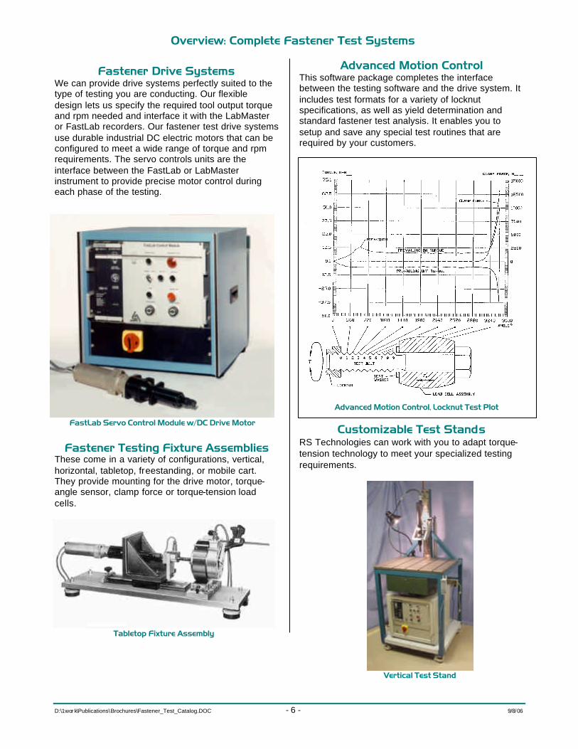
Fastener Drive Systems We can provide drive systems perfectly suited to the type of testing you are conducting. Our flexible design lets us specify the required tool output torque and rpm needed and interface it with the LabMaster or FastLab recorders. Our fastener test drive systems use durable industrial DC electric motors that can be configured to meet a wide range of torque and rpm requirements. The servo controls units are the interface between the FastLab or LabMaster instrument to provide precise motor control during each phase of the testing.
Fastener Testing Fixture Assemblies These come in a variety of configurations, vertical, horizontal, tabletop, freestanding, or mobile cart. They provide mounting for the drive motor, torque-angle sensor, clamp force or torque-tension load cells.
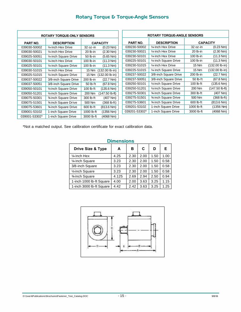
Advanced Motion Control This software package completes the interface between the testing software and the drive system. It includes test formats for a variety of locknut specifications, as well as yield determination and standard fastener test analysis. It enables you to setup and save any special test routines that are required by your customers.
Customizable Test Stands RS Technologies can work with you to adapt torque-tension technology to meet your specialized testing requirements.
Sample Test System ConfigurationsSample Test System Configurations Below are examples of our basic and complete test systems, along with some additional accessories. Refer to the following pages for complete descriptions and technical data for the individual components.
Basic Torque-Tension Test System This tabletop torque-tension test stand provides all you need to meet the torque-tension testing
requirements of most OEM and industry standards. It features a Model 960 2-channel recorder that records and provides the test data in numeric or graphic form. It can also upload the data to a laptop or desktop computer for further analysis. The system also includes a DC electric tool and controller, a rotary torque transducer, and a clamp force transducer. The system is completed with a fixture assembly with a slide bearing mounting for -the DC drive tool and mounting for the rotary torque sensor and clamp force load cell.
Part Number Description
080960-31958 Model 960 2-channel Recorder
08CLEC-00MTR DC Drive Motor, 15-150 Nm, 165 RPM max.
Complete Test System The complete fastener test system can perform a wide variety of automated and semi-automated tests on threaded fasteners. You can acquire, record, and plot basic torque, angle, and clamp load data, determine thread torque, underhead friction torque, friction coefficients, joint relaxation, joint yield, and tool performance characteristics. You can setup and test a wide variety of fastener types including prevailing torque locknuts.
The complete system starts with a LabMaster Pro module connected to a desktop or laptop computer. These let you setup and run the test, record all of the data inputs, and provide output in the form of numeric or graphic data. The system features a DC electric drive motor and servo controller to apply the torque, a torque-angle sensor to measure the input torque and fastener rotation, a research head to measure clamp load and thread torque, and a properly sized fixture assembly for mounting all components.
Part Number Description
083200-01000 Model 3200 LabMaster Professional
089200-00528 DC Drive Motor & Controller, 20-260 Nm
Model 960 PModel 960 Portable Recorderortable Recorder Portable Transient Recorder for Torque and Force Auditing of Threaded Fasteners
p Measure and Record Torque, Angle, and Clamp Load characteristics of threaded fasteners
p Perform Torque-Tension Verification Testing on fasteners to verify coating or plating performance
p Perform Signature Analysis for Clamp Force verification
p Test Torque or Torque-Angle power tools or Hand Torque Wrenches
Portable Data Recorder The Model 960 is a battery-powered, transient recorder with two transducer inputs and one angle input. It can serve as a portable threaded fastener laboratory for measuring fastener torque, angle, and clamp load. It is also ideal for auditing and certifying power tools and hand torque wrenches. The model 960 is a cost-effective, versatile, and easy to use recorder and can collect up to 500 rundowns. Its alphanumeric setup and calibration menus assure ease of operation. It can be used with all RS Technologies rotary torque-angle and clamp force transducers and other conventional strain gage transducers.
Applications Among many possible applications, the model 960 is designed for the following:
• Perform torque versus tension verification testing on fasteners and joints to verify the performance of coatings, lubricants, or plating
• Provide fastener torque versus angle signature analysis for clamp force verification
• Perform audit, certification, or tool room calibration of power tools and torque wrenches
• Perform dynamic monitoring of power tools on the plant floor to determine their performance capability
• Certify calibration factors for single spindle nutrunners and tools by monitoring the reference transducer and tool transducer simultaneously
Statistics After each rundown the Model 960 updates the statistics including high, within limits, and low lever readings, standard deviation, and Cpk.
Data & Communications Data and statistics can be printed via the parallel port. Data can be downloaded to a PC via the serial port for further analysis. Program updates are uploaded through the serial port.
Real-Time Plotting Capabilities The Model 960 lets you capture real time and peak readings for torque-angle, torque-clamp load, or torque-time and immediately display or plot the following, based on your instrument setup:
• Torque vs. Time
• Torque vs. Angle
• Angle vs. Time
• Tool RPM vs. Time
• Torque vs. Clamp Force
• Torque and Clamp vs. Angle
Model 960 Specifications Part Number .................................. 080960-31958
Torque and Force Input Channels Input Range:............................................ ±2.5 mV/V, ±4.5 mV/V,
±5 VDC or user selectable Excitation: .....................................4.5 VDC or 9 VDC (standard),
120 ma max. Resolution: ......................................................................... 16-bit Non-linearity:...................................................... 0.15% full scale Frequency Response: ...................................................... 25 kHz
Positive Voltage Peak Trap Circuit: ...................... 7 µs reset time Peak Threshold: .....................................Software Programmable Peak Reset: ..........................Manual or software programmable,
The LabMaster Professional is an advanced, multi-purpose system designed to test threaded fasteners, analyze bolted joints, and certify power tools. It’s comprised of two components: the LabMaster Pro module that contains data acquisition and drive motor interface capabilities, and a laptop or desktop PC running the LabMaster for Windows testing software. The module and computer interface via a USB port.
Simple Test Setup Employing full Windows functionality with drop-down menus and point-and-click features, the LabMaster for Windows software provides a user-friendly graphic interface that makes setting up tests and accessing data quick and easy. You can quickly make changes to existing test setups, easily select different tools and transducers, or view results of previous tests. An easily accessed transducer parameter and test setup directory further simplifies testing setup.
Easy Operation Once the test is set up, the LabMaster Pro module conducts all of the motor control and data acquisition operations. The recorded data are then displayed and managed on the computer for access to network printers, archiving, and communications.
Multiple Inputs Four analog inputs are available on the LabMaster Pro module (one with encoder input) to accept data signals from the following:
• Transducers • Strain gages • Load cells • Torque cells • Force washers • Bolt extensometers • Ultrasonic devices • Any 10 V analog device
High Speed Sampling The LabMaster data acquisition card provides high-speed sampling of up to 4 kHz (software selectable). Sampling can be done versus a time or angle basis.
Comprehensive Data LabMaster Pro systems with a torque-tension research head and a torque-angle sensor can measure and calculate the following:
from T=KDF) • Thread Friction Coefficient • Underhead Friction Coefficient
Statistical Calculations LabMaster Pro offers a variety of statistical reports in numeric and graphic form. Statistical plots of K3 sigma mean curves provide an insightful data summary.
Real-Time Display The LabMaster Pro and the LabMaster for Windows testing software provide real-time display, printing, plotting, and automatic saving of all measured data. A user-selectable automatic data save feature for both numeric and graphic data speeds technician testing time.
Variety of Plots Rundown data and plots may be viewed on the computer display, printed as hard copy, or saved for later data analysis. A number of configurable plots can be generated, some of which are shown on the facing page.
Complete Test Systems A complete torque-tension test system will typically include a rotary torque-angle transducer, a thread torque-tension research head, a DC electric tool and controller, and a printer for numeric and graphic data reports, all of which are available from RS Technologies.
Options Optional features include an auxiliary input for an ultrasonic interface, test drive motor control outputs, and a tabletop or mobile test cart.
Compatibility ..................................... TTL Optical Isolation ...................... Available
Computer Requirements
• Windows 98SE, 2000, or XP
• 512 MB RAM
• 60 GB hard drive
• CD-ROM drive
• USB 2.0 Port
RS Technologies can provide a precision dc electric drive system and test fixture assembly that will suit your testing requirements. The drives are durable, industrial-strength motors with servo controllers to provide precise control of the threaded fastener testing process. The torque output and speed of the motor are set by the testing software in the automatic mode or can be set and operated in a manual mode. Test fixture assemblies come in a tabletop configuration to provide mounting for the motor, torque-angle transducer, and torque-tension or clamp force load cell. Test stands or mobile carts are available at additional cost.
p Industry Standard Transducers compatible with all RS Technologies Fastener, Joint Analysis and Tool Certification Test Equipment, and most strain gage instruments and data collectors with low-level analog Inputs
p Integral part of Fastener Test Measurement System
p On-Board ID Microchip for use with RS Technologies data recorders
Specifications General Receptacle .............................................. Bendix PT02H-12-10P Mating Connector ............................ Bendix PT06A-12-10S(SR) Dimensions ........... Refer to Standard Torque Sensor Literature Torque Output at Rated Capacity ............................. 2 mV/V ±0.25% FS Shunt Calibration ........................ Matched at 2.00 mV/V ±0.25%
for 43.575 kOhm precision resistor Interchangeability .................................... Matched for mV/V and
shunt calibration ±0.3% Full Scale Nonlinearity .................................................... ±0.25% Full Scale Hysteresis ...................................................... ±0.25% Full Scale Recommended Excitation ........................... 10 VDC or AC RMS Bridge Resistance ......................................... 350 Ohms nominal Compensated Temperature Range ...................... +70 to +150°F Useable Temp Range .............................................. 0 to +200°F
Angle Magnetic Encoder ........ 360 Poles (540 poles on 3/4-inch drives
and 720 poles on 1-inch drives) Output .......................... A-B Track 90 degrees phase difference
flat over operating speed range Resolution w/Quadrature ....................... ¼ degree (3/16 degree
on ¾- inch drives and 1/8 degree on 1-inch drives)
Output Voltage ............................................. High 5V, Low 0.5V Power Required ..................................... 5 VDC @ 120 mA max. Recommended Maximum RPM ¼- inch ................................................................................. 5000 3/8-inch ............................................................................... 2500 ½ - inch ................................................................................. 2500 ¾ - inch ................................................................................. 2000 1-inch .................................................................................. 1000
Research Heads and CResearch Heads and Clamp Force Load Cellslamp Force Load Cells Measure and analyze threaded fastener characteristics in production lot testing or R & D studies!
p Perform laboratory evaluation of fastener tension and thread torque characteristics
p Measure fastener tension, thread friction torque, or both during rundown operations
p Test special devices such as locknuts, serrated underheads, thread-locking adhesives, and friction patches
p Measure effects of materials, surface finishes, plating, and coatings
p Use standard Skidmore-Wilhelm plate sets or order custom plates for special fasteners
p Slotted base makes it easy to secure to existing test fixtures
The fastener tension-thread torque research heads and fastener tension load cells manufactured by RS Technologies use a full bridge strain gage design. This complete line of fastener testing load cells provides a signal proportional to the tension developed in a test fastener when the tightening torque is applied. In addition, the research head version measures the thread torque (pitch torque plus
thread friction torque) at the same time. The tension or torque-tension output signals from either type of load cell are read using a FastLab or LabMaster recorder or some other conventional strain gage readout device. These load cells serve as an integral parts of a complete torque-tension fastener test system.
Model 9500 Torque-Tension Research Head Model 9810 Fastener Tension Load Cell
General Fastener Tension and Torque-Tension Load Cell Specifications Output at Rated Capacity ................................................... 2.0 mV/V, nominal Overload Capacity .............................................................. 50% of rated load Nonlinearity ....................................................................... ±0.2% of full scale Hysteresis .......................................................................... ±0.2% of full scale Zero Balance ......................................................................... ±1% of full scale Excitation Voltage ..................................................... ±10 vdc or ac rms, max. Bridge Resistance .......................... 350 Ohms, full bridge, bonded strain gage Compensated Temperature Range ............................................. 70 to 150 ºF Useable Temperature Range ........................................................ 0 to 200 ºF Temperature Effect on Zero .................................................... ±0.01% FS /ºF Temperature Effect on Output .................................... ±0.01% of Reading /ºF
9800 Series Fastener Tension Load Cells PART NO. FASTENER TENSION CAPACITY
059810-01153 15 kN (3,372 lbf)
059810-01253 25 kN (5,620 lbf)
059810-01104 100 kN (22,481 lbf)
059810-01304 300 kN (67,443 lbf)
059810-01504 500 kN (112,405 lbf)
9000 Series Fastener Torque-Tension Load Cells PART NO. THREAD TORQUE CAPACITY FASTENER TENSION CAPACITY
Fastener Force Washer TransduFastener Force Washer Transduccersers The Fastener Force Washer Transducers are ideal for use in threaded fastener torque-angle-tension testing!
p Measure and record tension characteristics of threaded fasteners
p Verify threaded fastener tension calculations
p Test actual fasteners in a laboratory or assembly environment
The Model 4000 Force Washer Transducers are miniature load cells designed specifically for measuring fastener clamping forces. The design provides high stiffness in a small package, making these load cells ideal for static and dynamic measurements on fasteners, tie rods, or similar structural test applications where space limitations exist. Force washer transducers come in a variety of English and metric sizes.
All transducers are carefully sealed and thoroughly tested prior to shipment. Two hardened steel washers are provided with each unit and should be mounted on either side of the transducer to minimize any transmitted rotational effects or spot loading. Refer to the illustration below. All units are furnished with a 5-foot long cable with pigtail leads.
Specifications Output at Rated Capacity ................................................... 2.0 mV/V, nominal Overload Capacity .............................................................. 50% of rated load Nonlinearity ....................................................................... ±2.0% of full scale Hysteresis .......................................................................... ±2.0% of full scale Zero Balance ......................................................................... ±5% of full scale Excitation Voltage ..................................................... ±10 vdc or ac rms, max. Bridge Resistance .......................... 350 Ohms, full bridge, bonded strain gage Compensated Temperature Range ............................................. 70 to 150 ºF Useable Temperature Range ........................................................ 0 to 200 ºF Temperature Effect on Zero .................................................... ±0.01% FS /ºF Temperature Effect on Output .................................... ±0.01% of Reading /ºF
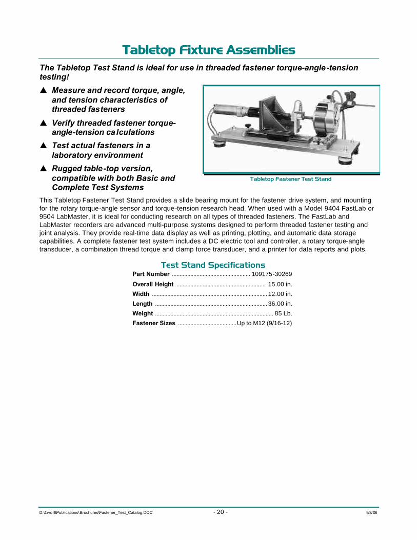
Tabletop Fixture AssembliesTabletop Fixture Assemblies The Tabletop Test Stand is ideal for use in threaded fastener torque-angle-tension testing!
p Measure and record torque, angle, and tension characteristics of threaded fasteners
p Verify threaded fastener torque-angle-tension ca lculations
p Test actual fasteners in a laboratory environment
p Rugged table-top version, compatible with both Basic and Complete Test Systems
This Tabletop Fastener Test Stand provides a slide bearing mount for the fastener drive system, and mounting for the rotary torque-angle sensor and torque-tension research head. When used with a Model 9404 FastLab or 9504 LabMaster, it is ideal for conducting research on all types of threaded fasteners. The FastLab and LabMaster recorders are advanced multi-purpose systems designed to perform threaded fastener testing and joint analysis. They provide real-time data display as well as printing, plotting, and automatic data storage capabilities. A complete fastener test system includes a DC electric tool and controller, a rotary torque-angle transducer, a combination thread torque and clamp force transducer, and a printer for data reports and plots.
Test Stand Specifications Part Number ................................................... 109175-30269
Overall Height .......................................................... 15.00 in.
Width ........................................................................... 12.00 in.
Length ......................................................................... 36.00 in.
Floor Mounted Fastener Test StandFloor Mounted Fastener Test Stand The Floor-Mounted Test Stand is ideal for use in threaded fastener torque-angle-tension testing of large fasteners up to M33!
p Measure and record torque, angle, and tension characteristics of threaded fasteners
p Verify threaded fastener torque-angle-tension ca lculations
p Test actual fasteners in a laboratory environment
p Rugged free-standing or table-top versions
The Floor-Mounted Fastener Test Stand provides mounting for the fastener drive system, rotary torque-angle sensors, and torque-tension research head or clamp force load cell. When teamed with a Model 9404 FastLab or 9504 LabMaster data recorder, it is ideal for conducting research on large threaded fasteners. The FastLab and LabMaster recorders are advanced multi-purpose systems designed to perform threaded fastener testing and joint analysis. They provide real-time data display as well as printing, plotting, and automatic data storage capabilities. A complete fastener test system includes a DC electric tool and controller, a rotary torque-angle transducer, a combination thread torque and clamp force transducer, and a printer for data reports and plots.
Test Stand Specifications Part Number ........................................... 109483-32025
Overall Height .................................................. 50.00 in.
Width ................................................................... 48.00 in.
Length ................................................................. 38.67 in.
Wheel Nut Test StandWheel Nut Test Stand Ideal for use in wheel nut torque tension testing and analysis!
p Measure and record torque, angle, and tension characteristics of various wheel type and nut combinations
p Verify wheel torque and angle specifications
p Test actual wheels--no additional machining costs are required
p Rugged industrial aluminum framing with space saving vertical design
The Wheel Nut Test Stand, when teamed with a FastLab or LabMaster test system, is ideal for conducting research on automotive and light truck wheels and wheel nuts. It is a complete, automated threaded fastener test stand. The FastLab and LabMaster recorders are advanced multi-purpose systems designed to perform threaded fastener testing and joint analysis. They provide real-time data display as well as printing, plotting, and automatic data storage. A complete wheel nut test system also includes a DC electric tool and controller with rotary torque transducer, combination thread torque and clamp force transducer, and a printer for data reports and plots.
Wheel Nut Test Stand Components
Part Number Description
102145-32429 Wheel Nut Test Stand, Fixtures, and Enclosures
102145-34151 Wheel Nut Test Stand, Fixtures, and Enclosures
059600-02104 Torque-Tension Research Head 150 Nm (110 lb-ft)/ 100 kN (22,480 lbf)
059600-02154 Torque-Tension Research Head 300 Nm (221 lb-ft)/ 150 kN (33,720 lbf)
059625-02304 Torque-Tension Research Head 800 Nm ( 587 lb-ft) / 300 kN (67,443 lbf)
Test Stand Specifications Overall Height ..................................................... 85.5 in.
Width ......................................................................36.0 in.
Depth ......................................................................36.0 in.
Fastener Drive SyFastener Drive Sysstemstems Accurate, precise, and dependable torque required for threaded fastener torque-angle-tension testing!
Fastener Drive Systems are available in a variety of speed and torque configurations, depending upon the size and type of fasteners, and your testing requirements. They are comprised of a rugged, heavy-duty industrial dc electric motor and a dependable servo controller that together provide the precise and accurate torque that is required for threaded fastener testing. They can be supplemented with torque multipliers to extend their torque or speed range.
Either a FastLab or a LabMaster instrument provides control. The FastLab and LabMaster are advanced multi-purpose systems designed to perform automated threaded fastener testing and joint analysis. They provide real-time data display as well as printing, plotting, and automatic data storage capabilities.
A complete test system also includes a rotary torque-angle transducer, a combination thread torque and clamp force transducer, a test fixture assembly for mounting all components, and a printer for data reports and plots.
Fastener Test Drive Systems Part Number Description Capacities
089200-00524 Cooper #570524 0-614 RPM 54 Nm (39.8 lb-ft)
089200-00526 Cooper #570526 0-250 RPM 132 Nm (97.4 lb-ft)
089200-00528 Cooper #570528 0-127 RPM 260 Nm (192 lb-ft)
089400-00606 Cooper #570606 0-192 RPM 391 Nm (288 lb-ft)
089600-00621 Cooper #570621 0-102 RPM 781 Nm (576 lb-ft)
089800-00631 Cooper #570631 0-102 RPM 1,073 Nm (791.4 lb-ft)
089120-01000 Cooper #571000 0-74 RPM 1,485 Nm (1,095 lb-ft)
AdvancAdvanced Motion Control Fastener Testing Softwareed Motion Control Fastener Testing Software Conduct comprehensive basic research cycle testing and production quality control in-process audits!
p Now Available with LabMaster Pro!
p Five Basic Setups Programmed According to Accepted Test Standards
p Standard Setups can be easily modified to meet your own specifications
Standard Torque Tension Cycle This testing lets you do the following:
p Specify a torque or clamp load shutoff point
p Tighten and loosen a single fastener up to 30 times
p Record clamp forces at four torque points, or record torque values at four clamp loads
p Print out a statistical test summary of clamp force or torque points and loosening torque
p Print out a plot of the torque and tension mean and ±3 sigma curves
Locknut Attaining Clamp Load This testing lets you do the following:
p Specify a clamp load shutoff point
p Tighten and loosen up to 30 times on a single fastener and nut installation
p Print out a statistical summary of measured values such as prevailing on torque, minimum or maximum prevailing off torque, and torque to achieve specified clamp load
Locknut No Clamp Load Attained This testing lets you do the following:
p Start controlled motion tests with negative threshold torque (i.e., -10 Nm) so that recording starts as soon as motion begins
p Measure breakthrough torque as well as prevailing on torque and maximum and minimum off torque for up to 30 samples
p Print out a statistical summary of measure values such as breakthrough torque, maximum prevailing on torque, and maximum or minimum prevailing off torque
Locknut IFI Specifications This type of testing lets you do the following:
p Specify clamp load shut off point
p Third, fourth, and fifth cycles do not attain clamp load with up to 30 samples for each summary report
p Print out statistical data for breakthrough on first cycle, maximum on torque first cycle, torque to achieve specified clamp load, and fifth off torque minimum prevailing torque
Locknut Chrysler Specifications This test routine is the same as for the IFI specifications except that clamp load is attained on all five cycles.
SR1 Bolt Calculation Software SR1 is a Windows™-based software program that calculates and charts data for high-stress, bolted joints in accordance with the German Standard VDI 2230. It can be used for bolted joints with concentric or eccentric strain and load. SR1 uses the calculated data to produce scale drawings of all components of the bolted joint and a graphic representation of several important graphs and diagrams. This output lets you not only view the assembly from all angles but also estimate such important factors as clamp force per degree of rotation, bolt stretch, yield point, and safety factors.
Who Should Use SR1? Anyone involved in the engineering, design, test, measurement, and control of threaded fastener assemblies will find that the SR1 software is a “must have” tool. Practicing engineers, professors, instructors and students will all find that the SR1 software is perhaps the best technical guide to engineering, designing, and analyzing bolted joints. With SR1 they can evaluate all previous designs and, with past experience as a guide, use this information to assist in creating more reliable new designs.
System RequirementsSystem Requirements SR1 will run easily on an IBM-PC compatible computer running Windows 95/98/NT/2000.
How Do You Use SR1?How Do You Use SR1? First, SR1 calculates and suggests different combinations of bolt diameters and strength classes based on the preliminary input of the amount and type of load, its application, and the tightening method.
Database for Bolts and ThreadsDatabase for Bolts and Threads Next, you use SR1 to define the bolt and nut. SR1 contains extensive databases for bolts, nuts, and thread sizes and types. The standard databases include information for most commonly used metric
and English bolt type and dimensions, ranging from M1.6 to M160, and from 0-80 to 4-inch by 4. You can append the databases with specially sized fasteners and define any number of bolt types. Tightening factor and tool precision discrepancies are also available from an appendage database.
Clamping PartsClamping Parts Third, you can freely define the dimensions, material, e-Modulus, and permissible surface pressure for up to ten clamping pieces. The materials database can be appended to include additional materials and associated factors to meet your needs. Experienced users can create special effects with clamping pieces to modify the SR1 deflection calculations and supplement FEA calculations and torque-angle signature measurements.
Friction CoefficientsFriction Coefficients Next, you enter the friction coefficients, either from the database or as derived from experimental testing. The most important friction coefficients for thread, head seat, and seam are available for use from the integrated SR1 database. You can append the friction coefficient database to include new combinations of materials based on data determined experimentally. Such testing can be done using fastener research test machines that perform tests according to DIN 946, such as the RS Technologies LabMaster Model 9504. The slope of the torque-angle signature for a given bolted joint can then be used to verify the uniformity of friction effects.
AAssembly Methodssembly Method Finally, you specify the scatter factor of the assembly process. Certain types of tooling can introduce a greater amount of scatter than others. The amount of scatter relating to tooling is an important factor when analyzing a critical bolted joint and SR1 makes it easy for you to setup and append the related database.
Data OutputsData Outputs Once the bolted joint has been thoroughly specified, you can obtain any of the numerous charts graphs and printouts provided by SR1.
Safety FactorsSafety Factors Perhaps, the most important output of SR1 are the safety factor evaluations for thread strip, embedment, bolt stretch, etc. A careful review of the safety factors will reveal the presence of any critical flaws in the assembly.
M-Alpha and F-Alpha Diagrams Two of the most important enhancements to the VDI standard, provided by SR1, are the M-Alpha (torque vs. angle) and F-Alpha (clamp force vs. angle) diagrams. These show torque or clamping force as a function of angle of turn starting at the elastic origin. The elastic origin is located by projecting the tangent of the tightening curve at the preload point back to the starting torque level. The location of the elastic origin is important because
the tension of the joint is directly proportional to the angle of turn from that point. Correlation of the M-Alpha and F-Alpha diagrams allows estimations of joint integrity. These diagrams also present summary information for the joint. This includes fastener size and grade, friction coefficients, and calculated values for K based on input from friction
coefficients and thread pitch. Also presented are critical safety factors for key design considerations such as thread strip and underhead embedment.
NOTE The M-Alpha and F-Alpha diagrams have been included with SR1 to provide a link to the powerful torque-angle signature analysis methods developed by RS Technologies, Ltd. They can be correlated to comparable diagrams provided by fastener test equipment such as the Model 9504 LabMaster. They add major practical elements to the already powerful tools of the VDI 2230 analysis.
Load Extension DiagramLoad Extension Diagram After the calculations are complete, you can display or print load extension diagrams for either assembly or working status. These diagrams illustrate the stretch of the bolt and the compression of the parts being clamped. The spring rate and stiffness of the clamped parts is estimated by up to 10 user-definable cylinders or disks that simulate the geometry of the joint.
PrintoutPrintout After all elastic compliances, forces, loads, and tightening moments are calculated, all data can be displayed on-screen, sent to a printer, or saved.
Provides TraceabilityProvides Traceability The SR1 program can provide important documentation for bolted joint designs where complete traceability is required according to ISO 9000 and QS-9000. It is important to note that SR1 is a design guide that must be supplemented by experimental measurements to verify all calculations. The individual user must independently verify the actual tightening results obtained for each specific assembly. Material strengths and friction coefficients and key dimensions must be documented to assure that actual practice corresponds to the design assumptions.
CAD Interface SR1 generates a scale drawing of the bolted joint, showing the bolt, clamping piece, washers, and the nut. Transfer of drawings and data to CAD is done by saving the file in a DXF or IGES file format.
Help SystemHelp System SR1 provides useful design suggestions when you are uncertain of dimensions or factors. When possible error conditions occur, appropriate messages are displayed to provide a description and suggested solution.
Network VersNetwork Versiionon Network licenses are available to enable access to the program by one or more users at their own networked workstations. The number of individuals who can access the program at any one time can be arranged according to the needs of your fastener engineering department.
What You Get with SR1What You Get with SR1 The SR1 package includes installation software, complete with the easy-to-install program, help system, and sample data, a user manual with application examples and a calculation basis worksheet, forms for input data, and a license agreement for an indefinite period of time with update service.
Software Maintenance and HotlineSoftware Maintenance and Hotline We are constantly working to extend and improve the SR1 software. We keep our customers informed about updates and new features at regular
intervals. Additional technical support is available from RS Technologies to assist in training users as well as providing important consultation on questions regarding bolted joint design, assembly tools, and test measurements related to fasteners.
University & Education ProgramsUniversity & Education Programs The Student Edition of SR1 is a demonstration version that you may download at any time from the World Wide Web at:
http://www.hexagon.de/sr1_e.zip
No commercial use is permitted for the demo version, which is provided with built-in limitations. Educational packages, licensed for teaching purposes only, are available for the individual educator at a special price. A single university or computer room can obtain a room license copy of the SR1 program. All room licensed copies are identified with the license serial number and include full operating features but are licensed for teaching purposes only. Educators who wish to use the SR1 software for engineering consulting must purchase a full licensed copy of the program.
FastPlotFastPlot™™ for Windows for Windows®® Powerful, Easy-to-use Data Transfer & Plotting!
p Transfer recorded data from the Model 960 to laptop or desktop computer
p Store data using familiar Windows interface
p Plot graphic data using convenient dialog box format
p Easy-to-use Zoom feature
FastPlot for Windows is designed for use in uploading numeric and graphic data from the Model 960 recorder to a laptop or desktop personal computer for plotting, printing or storage. It combines serial port data transfer, storage, and graphic plotting into one application. You can record your data in the field, bring it back to your lab or office, quickly upload it, view it, and send it to your computer printer, or save it to a network drive.
FastPlot offers a variety of plotting capabilities in one easy to use package. Virtually any of the recorded inputs can be graphed vs. any of the others. For example, if you have recorded, torque, angle, clamp
load and time, you can graph torque vs. angle, torque vs. clamp load, torque and clamp load vs. angle, etc. FastPlot also lets you open data files previously recorded in RST format by other devices from RS Technologies such as the LabMaster or FastLab recorders.
FastPlot also provides the capability of plotting multiple rundowns for graphic comparison including an X-axis offset for additional clarity in presentation. A zoom feature lets you click and drag a box around a particular segment of the graph that you would like to view in greater detail. You can also add a title line to your plot for identification or labeling purposes.
Threaded Fastener Testing Services Threaded Fastener Testing Services RS Technologies provides a wide range of threaded fastener testing services at our fastener testing laboratory in Farmington Hills, Michigan. Our fastener test lab is accredited by A2LA for Mechanical Testing of fasteners according to ISO 17025. Our testing and support capabilities include the following:
p Torque-to-Failure Testing where the fasteners are driven to failure on actual assemblies. Torque-angle signatures can be plotted and analyzed to determine the point of yield, point of fracture, and other important aspects of the joint. This data can be used to help establish or verify assembly specifications among other uses. We can also use our exclusive M-Alpha graphing capability to estimate the relative difference in clamp loads produced with different coatings, plating, finishes, etc.
p Torque-Tension Testing where the fasteners are mounted in a tension load cell with test washers or coupons of actual materials to determine the relationships between torque, angle of rotation, and tension. Special test routines include those required for testing prevailing torque locknuts according to widely accepted test specifications. A wide variety of graphs can be generated depending upon your data requirements.
p Friction Analysis Testing where the fasteners are mounted in a thread torque-tension load cell. In this test we can break out the thread torque from the input torque to determine the underhead torque and thread torque and also calculate friction coefficients for the underhead and thread regions, as well as the so-called “nut factor”, K.
p Yield Determination Testing where the fastener is mounted in a tension load cell with test washers or coupons of actual materials to determine the yield point of the fastener.
p Bolted Joint Modeling and Analysis whereby we model the joint using our exclusive SR1 software to calculate the stresses present in the joint. SR1 is an enhanced VDI-2230 calculation method that we use to close the loop between fastener design and application. We can use SR1 to provide correlation between the results of any related experimental testing as described above.
p We offer Engineering Consulting Services to assist customers research critical joints. We can combine testing in the field at your facility with testing at our laboratory to provide a complete picture of what happens when the fastener is tightened.
p We also offer Fastener Technology Training Seminars that provide theory and application information to help you understand the complex relationships of torque, angle, tension, friction, strength of materials, and other factors that affect a bolted joint. Topics also include fastener engineering, torque audit methods, and assembly tool verification and calibration.
Depending upon your test requirements, we can combine the tests described above as needed to provide you with the data that you need. Contact our Sales Department for a quotation on threaded fastener testing services.