Send Orders for Reprints to [email protected]32 The Open Civil Engineering Journal, 2015, 9, 32-43 1874-1495/15 2015 Bentham Open Open Access Exploration and Grouting of Large-Scale Water Capsule in the Fault Fracture Zone of Yonglian Tunnel Qingsong Zhang, Peng Li*, Xiao Zhang, Shucai Li, Weijie Zhang and Qian Wang Geotechnical and Structural Engineering Research Center, Shandong University, Jinan, Shandong, 250061, China Abstract: A large-scale water capsule was formed after 8 times inrush of mud and water in Yonglian tunnel. The capsule seriously inhabited the construction of the tunnel. By combining with the geological conditions in tunnel site, the causes and characteristics of the water capsule were analyzed. Its spatial location and size were explorated by comprehensive exploration methods. In order to control the water capsule, the treatment scheme composed by full-face curtain grouting in left tunnel and decompression by drainage in right tunnel was made, and the composite and controlling grouting methods were proposed. The composite and controlling grouting technology was applied in the treatment. It was composed by grouting parameters selection, grouting material and technology optimization by means of numerical simulation, model experiment and SEM microscopic experiment. By means of the grouting effect examination methods including P-Q-t curve, examination holes, surrounding rock deformation monitoring and excavation, the water capsule was proved to be treated successfully. The engineering case provides a reference for the similar engineering to some extent. Keywords: Composite and controlling grouting technology, full-face curtain grouting, grouting examinationmethods, inrush of mud and water, Yonglian tunnel, fault fracture zone, water capsule. INTRODUCTION With the rapid development of highways, more and more mountain tunnels are to be constructed in China. Fault fracture zone is one of the common unfavorable geological conditions during the construction process [1-3]. Fault fracture zone with fractured surrounding rock and complex lithology will turn into unstable mud under the conditions of abundant groundwater, then inrush of mud and water which seriously inhabited the safety of construction is easy to induce. Some researchers have investigated the treatment methods for fault fracture zone [4, 5], and grouting methods such as curtain grouting, grouting with small pipe and tube- shed grouting are commonly used methods [6-8]. However, studies on exploration and treatment of large-scale water capsule in the fault fracture zone are few. Given that, by analyzing geological conditions, applying drilling method, full-face curtain grouting scheme, the composite and controlling grouting methods and technology, and grouting examination methods, the water capsule can be treated successfully. 1. THE ENGINEERING SITUATION Yonglian tunnel with a length of 2500 m is located on expressway from Ji’an City to Lian’hua City, in Jiangxi *Address correspondence to this author at the Shandong University Qianfo Mountain Campus, Jingshi Road, Lixia District, Ji’nan City, Shandong Pro 250061, China; Tel: 15168841003; Fax: +86-0531-88395428; E-mails: [email protected]; [email protected]Province, China. There were a large number of regional faults and secondary faults with rich water such as fault-2 in tunnel. Because of its complex geological conditions, Yonglian tunnel becomes the key engineering of the expressway. 1.1. Geological Conditions on Tunnel Site The geological structures, hydrogeology conditions, topography, geomorphology, and lithological features of Yonglian tunnel are analyzed as follows. (1) Fault structure The angle of regional fault and fault-2 are respectively 0°∠75° and 90°∠84°. In addition, rock located in the juncture of faults is broken. All these factors provide favorable conditions for groundwater influx, storage and movement. (2) Topography and geomorphology The terrain is lower than other places at the juncture of faults. It resulted in the influx of groundwater. (3) Lithological features Fault rock and weathered shale containing a great deal of montmorillonite are easy to disintegrate and turn into mud when come into contact with water, then they lose the ability to stabilize. (4) Groundwater Adequate rainwater in tunnel site provides stable source for groundwater which accelerates rock softening and decreases the strength of surrounding rock.
32 The Open Civil Engineering Journal, 2015, 9, 32-43
1874-1495/15 2015 Bentham Open
Open Access
Exploration and Grouting of Large-Scale Water Capsule in the Fault Fracture Zone of Yonglian Tunnel
Qingsong Zhang, Peng Li*, Xiao Zhang, Shucai Li, Weijie Zhang and Qian Wang
Geotechnical and Structural Engineering Research Center, Shandong University, Jinan, Shandong, 250061, China
Abstract: A large-scale water capsule was formed after 8 times inrush of mud and water in Yonglian tunnel. The capsule
seriously inhabited the construction of the tunnel. By combining with the geological conditions in tunnel site, the causes
and characteristics of the water capsule were analyzed. Its spatial location and size were explorated by comprehensive
exploration methods. In order to control the water capsule, the treatment scheme composed by full-face curtain grouting in
left tunnel and decompression by drainage in right tunnel was made, and the composite and controlling grouting methods
were proposed. The composite and controlling grouting technology was applied in the treatment. It was composed by
grouting parameters selection, grouting material and technology optimization by means of numerical simulation, model
experiment and SEM microscopic experiment. By means of the grouting effect examination methods including P-Q-t
curve, examination holes, surrounding rock deformation monitoring and excavation, the water capsule was proved to be
treated successfully. The engineering case provides a reference for the similar engineering to some extent.
Keywords: Composite and controlling grouting technology, full-face curtain grouting, grouting examinationmethods, inrush of mud and water, Yonglian tunnel, fault fracture zone, water capsule.
INTRODUCTION
With the rapid development of highways, more and more mountain tunnels are to be constructed in China. Fault fracture zone is one of the common unfavorable geological conditions during the construction process [1-3]. Fault fracture zone with fractured surrounding rock and complex lithology will turn into unstable mud under the conditions of abundant groundwater, then inrush of mud and water which seriously inhabited the safety of construction is easy to induce.
Some researchers have investigated the treatment methods for fault fracture zone [4, 5], and grouting methods such as curtain grouting, grouting with small pipe and tube-shed grouting are commonly used methods [6-8]. However, studies on exploration and treatment of large-scale water capsule in the fault fracture zone are few. Given that, by analyzing geological conditions, applying drilling method, full-face curtain grouting scheme, the composite and controlling grouting methods and technology, and grouting examination methods, the water capsule can be treated successfully.
1. THE ENGINEERING SITUATION
Yonglian tunnel with a length of 2500 m is located on expressway from Ji’an City to Lian’hua City, in Jiangxi
*Address correspondence to this author at the Shandong University Qianfo Mountain Campus, Jingshi Road, Lixia District, Ji’nan City, Shandong Pro
Province, China. There were a large number of regional faults and secondary faults with rich water such as fault-2 in tunnel. Because of its complex geological conditions, Yonglian tunnel becomes the key engineering of the expressway.
1.1. Geological Conditions on Tunnel Site
The geological structures, hydrogeology conditions, topography, geomorphology, and lithological features of Yonglian tunnel are analyzed as follows.
(1) Fault structure
The angle of regional fault and fault-2 are respectively 0°∠75° and 90°∠84°. In addition, rock located in the juncture of faults is broken. All these factors provide favorable conditions for groundwater influx, storage and movement.
(2) Topography and geomorphology
The terrain is lower than other places at the juncture of faults. It resulted in the influx of groundwater.
(3) Lithological features
Fault rock and weathered shale containing a great deal of montmorillonite are easy to disintegrate and turn into mud when come into contact with water, then they lose the ability to stabilize.
(4) Groundwater
Adequate rainwater in tunnel site provides stable source for groundwater which accelerates rock softening and decreases the strength of surrounding rock.
Exploration and Grouting of Large-Scale Water Capsule The Open Civil Engineering Journal, 2015, Volume 9 33
1.2. Formation and Characteristics of the Large-scale Water Capsule
From July 2, 2012 to August 19, as Fig. (1) shows that 8 times inrush of mud and water with large scale occurred in the left tunnel, and the volume of gushing mud and water was more than 50,000 m
3 in total. Because of it, mud filled
the completed section of tunnel with a length of 30 m, in addition, a large number of construction machines and steel arch centering were damaged during the inrush of mud and water.
Frequent inrushs of mud and water carried a lot of mud from surrounding rocks to tunnel face, then a large-scale cavity containing the mixture of mud and water formed in front of tunnel face, which we called the large-scale water capsule. Inhibiting seriously the normal construction of tunnel seriously, the characteristics of water capsule are large-scale, pressure-bearing, mixed and dynamic. Because of the water capsule, inrush of mud and water could occur again at any time, so it is necessary to treat it timely.
2. EXPLORATION OF WATER CAPSULE
After the inrush of mud and water, water capsule becomes the key factor to determine whether the tunnel can be excavated successfully, so its spatial location and scale
were necessary to explore. By prode borehole and transient electromagnetic prode method, the spatial location and scale of the water capsule were explored to provide reference for grouting.
2.1. Prode Borehole Method
2.1.1. Design Parameters of Boreholes
Based on the principle of uniform, 6 boreholes were designed in the tunnel face of left tunnel (ZK91+330), and 3 boreholes in work chamber of right tunnel (YK91+344.5). The parameters of boreholes are shown in Table 1.
2.1.2. Lithology and Water Exposed by Boreholes
By coring and measuring the amount of water, the characteristics of lithology and water exposed by boreholes can represent the geological conditions in front of tunnel face. For example, lithology and water exposed by C-3 borehole are shown in Table 2.
As Table 2 and Fig. (2) show the gushing water exposed by C-3 borehole presents 3 times sudden changes, and the maximum instantaneous velocity and water pressure can reach 160m
34 The Open Civil Engineering Journal, 2015, Volume 9 Zhang et al.
Fig. (2). Inrush water exposed by C-3 borehole.
2.1.3. Results of Prode Boreholes
Based on the characteristics of lithology and water exposed by 9 prode boreholes, the conclusions can be drawn as follows:
(1) The phenomenon that gushing water presented sudden change appeared frequently in left tunnel from ZK91+ -340 to ZK91+365. There were a lot of gushing water
spots with instantaneous rate and pressure above 100 m
3/h and 1 MPa, respectively.
(2) The rock located on the left tunnel from ZK91+340 to ZK91+365 is extremely broken, and the fault gouge
without the ability to stabilize is distributed widely.
2.2. Transient Electromagnetic Method
2.2.1. The Array-layout Method
Applying the array-layout method as shown in Fig. (3), four fixed transient electromagnetic loops containing 81 receiving points with the size of 4m×4m were layed on the grouting wall.
As shown in Fig. (4), there was a large area with low resistivity in front of the tunnel face. It represented that the filling medium was the mixture of mud and water.
(2) Resistivity distribution As shown in Fig. (5), the resistivity distributed from ZK91+340 to ZK91+370 was low, so we can conclude that the filling medium is the mixture of mud and water.
In a word, the results of prode borehole and transient electromagnetic prode methods are highly consistent, then
Table 1. Design parameters of boreholes.
Label Location of boreholes Declination (°) Vertical angel (°) Length(m)
C-3 Left tunnel 2.5 11.3 40
E-2 Left tunnel -8.8 0 40
E-6 Left tunnel 10 0 40
G-1 Left tunnel -10.3 -10.3 40
G-6 Left tunnel 10.3 -10.3 40
H-3 Left tunnel -0.4 -15 40
TK-1 Right tunnel 0 3 40
TK-2 Right tunnel 5 10 40
TK-3 Right tunnel 20 15 40
Table 2. Lithology and water exposed by C-3 borehole.
Footage(m) Chainage Lithology Instantaneous value of
Exploration and Grouting of Large-Scale Water Capsule The Open Civil Engineering Journal, 2015, Volume 9 35
we can conclude that the large-scale water capsule is distributed from ZK91+340 to ZK91+365.
3. GROUTING SCHEME DESIGN FOR WATER CAPSULE
According to the geological conditions explorated by exploration holes and transient electromagnetic method, the treatment scheme including full-face curtain grouting on the left tunnel and reducing pressure by drainage on the right tunnel was done.
3.1. Full-face Curtain Grouting on Left Tunnel
By dividing into two sections, full-face curtain grouting as shown in Fig. (6) was applied on the left tunnel, and the thickness of grouting reinforcement cycle was designed to be 8 m. There were 174 grouting boreholes in total including 124 curtain grouting holes, 21 vault grouting holes, 8 supplement grouting holes and 21 inspection holes. More grouting boreholes were designed on the right side of tunnel face in order to carry out a strengthening reinforcement.
3.2. Decompression by Drainage on the Right Tunnel
Abundant groundwater resulted in a high water pressure, so it was difficult to inject slurry into the water capsule. For this reason, 6 deep drainage boreholes were designed in the working chamber of right tunnel to cut off the water source of water capsule. In this way, the deep groundwater was transported to right tunnel, then the pressure and volume of water capsule were reduced largely which was beneficial for grouting.
4. GROUTING PARAMETERS SELECTION AND GROUTING MATERIAL OPTIMIZATION
By means of numerical simulation, model experiment and SEM microscopic experiment, we carried out grouting parameters selection and grouting material optimization to guide grouting.
4.1. Grouting Parameters Selection
4.1.1. Thickness of Grouting Reinforcement Cycle
Based on the principle of fluid-solid interaction, gushing water per meter was calculated by COMSOL under different reinforcement cycle thickness (d) and impermeability coefficient (N). N is defined as follows:
N=kw/kg (1)
In this formula, kw stands for the permeability of surrounding rock, and kg stands for the permeability of grouting reinforcement cycle.
The basic parameters of calculation model are shown in Table 3.
The curves of gushing water per meter under 11 kinds of reinforcement cycle thickness and 10 kinds of impermeability coefficients are shown in Fig. (7). According to the curve, under the same impermeability coefficient, gushing water per meter decreases gradually with the
Fig. (3). Array-layout method.
Fig. (4). Distribution of overall resistivity.
Fig. (5). Resistivity distribution from ZK91+340 to ZK91+370.
36 The Open Civil Engineering Journal, 2015, Volume 9 Zhang et al.
increase of reinforcement cycle thickness. However, when the reinforcement cycle thickness is more than 8 m, gushing water per meter is steady approximately, so a thickness of 8m is very suitable for grouting reinforcement. Furthermore, thestress field, displacement field and plastic zone of surrounding rock were calculatedas shown in Fig. (8).
4.1.2. Other Key Parameters
Based on the groundwater pressure, stratigraphic characteristics and related engineering experience [9-11], we selected shallow grouting pressure, deep grouting pressure, grouting diffusion radius and distance between holes to be 2 MPa, 4-6 MPa, 2 m and 4 m, respectively.
Table 3. Basic parameters of calculation model.
Name Size(m) Modulus of
elasticity(GPa) Gravity(KN/m3) Poisson’s ratio Internal friction angle (°/) Cohesion(MPa) Permeability(m2)
The fourth grade
surrounding rock 200×210 3.7 21.5 0.325 33 0.45 5.0×10⁻¹²
Grouting
reinforcement
cycle
d 18.5 19 0.21 45 0.9 5.0×10⁻¹³
Lining 0.8 25 25 0.25 50 1.5 5.0×10⁻¹³
Fig. (7). Curves of gushing water per meter.
Table 4. The arrangement and results of test.
The parameters of
samples before grouting
The average uniaxial compressive
strength before grouting (MPa) Label The grouting parameters
Exploration and Grouting of Large-Scale Water Capsule The Open Civil Engineering Journal, 2015, Volume 9 37
4.2. Grouting Material Optimization
In order to research on the reinforcement effect of single cement waterglass slurry for fault gouge inside water capsule, a set of model experiment device was developed.
4.2.1. The Design of Model Experiment
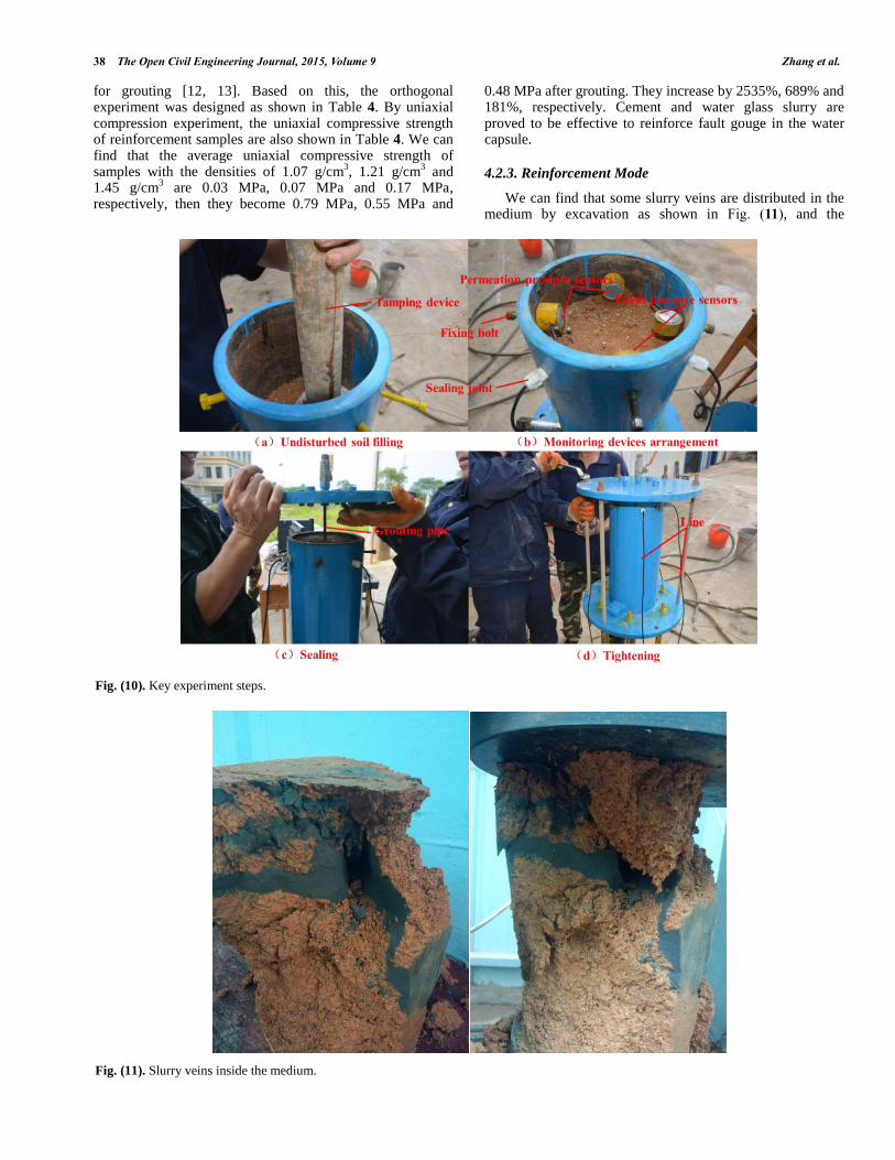
As shown in Fig. (9), the model experiment device is composed by grouting module, reinforcement module and information monitoring module. The experiment process
includes tunnel undisturbed soil filling, monitoring devices arrangement and line connection, sealing and tightening, slurry modulation and pipe connection, grouting and information monitoring, uniaxial compression experiment. Some key steps in model experiment are shown in in Fig. (10).
4.2.2. Arrangement and Results of Model Experiment
A number of studies show that grouting material, grouting pressure and medium are the most important factors
38 The Open Civil Engineering Journal, 2015, Volume 9 Zhang et al.
for grouting [12, 13]. Based on this, the orthogonal experiment was designed as shown in Table 4. By uniaxial compression experiment, the uniaxial compressive strength of reinforcement samples are also shown in Table 4. We can find that the average uniaxial compressive strength of samples with the densities of 1.07 g/cm
3, 1.21 g/cm
3 and
1.45 g/cm3 are 0.03 MPa, 0.07 MPa and 0.17 MPa,
respectively, then they become 0.79 MPa, 0.55 MPa and
0.48 MPa after grouting. They increase by 2535%, 689% and 181%, respectively. Cement and water glass slurry are proved to be effective to reinforce fault gouge in the water capsule.
4.2.3. Reinforcement Mode
We can find that some slurry veins are distributed in the medium by excavation as shown in Fig. (11), and the
Exploration and Grouting of Large-Scale Water Capsule The Open Civil Engineering Journal, 2015, Volume 9 39
reinforcement mode is mainly the fracturing grouting and compaction grouting. By supporting and compaction roles of slurry veins, the strength of medium is highly improved. It is defined as skeleton reinforcement mode.
4.2.4. SEM Microscopic Experiment
In order to analyze reinforcement effect of reinforcement samples in microscopic view, the SEM microscopic experiment was developed, and the fault gouge sample with serial number 4 was selected as typical sample which was increased by 1000 times. Before and after grouting, the results of SEM microscopic experiment are respectively shown in Fig. (12).
It was found that the structure of fault gouge sample was very loose before grouting, however, it becomes very dense after grouting, and particles were been glued together into a whole, in this way, the fault gouge was reinforced effectively.
5. COMPOSITE AND CONTROLLING GROUTING METHOD AND TECHNOLOGY
In view of complex engineering factors, highly anisotropic structure and hydrogeology conditions in Yonglian tunnel, single grouting method and technology were not found to be effective to treat the water capsule and
its affected area, based on this, the composite and controlling grouting method and technology were proposed.
5.1. Composite and Controlling Grouting Method
Composite and controlling grouting method applies multiple grouting materials, technology and reinforcement modes to improve the impermeability, strength and stability of fault gouge. At the same time, grouting process controlling and grouting safety controlling are applied to ensure construction safety.
5.1.1. Composite Grouting Methods
(1) Composite application of grouting materials
Cement and waterglass slurries have the ability to control gelation time and resist dispersion, and cement slurry has the advantages that it is easy to inject and its later strength is higher. In order to control diffusion range and ensure reinforcement effect, cement and waterglass slurry were used alternately according to the actual structure characteristics and hydrogeology conditions.
(2) Composite application of grouting technology
The surrounding rock in shallow area is relatively complete, so the complete hole grouting technology was applied to save time. In the middle of water capsule and its
Table 5. Lithology and gushing water exposed by JC-13 and JC-16.
Label The lithology The rate of gushing water (L/min·m-1)
JC-13
3m-6m: Solidification body of slurry;
7m-16m: Mixed solidification body of slurry and fault gouge;
17m-25m: Mixed solidification body of slurry and breccia;
26m-31m: Mixed solidification body of slurry and fault gouge.
0.1
JC-16
3m-9m: Mixed solidification body of slurry and fault gouge;
10m-21m:Mixed solidification body of slurry and breccia;
22m-31m: Mixed solidification body of slurry and fault gouge;
32m-35m: Solidification body of slurry.
0.05
(a) Fault gouge sample before grouting (b) Fault gouge sample after grouting
40 The Open Civil Engineering Journal, 2015, Volume 9 Zhang et al.
affected area, the medium was fault gouge, so the advancing segmentation grouting technology was applied to conduct gradual reinforcement. In the depth of water capsule and its affected area, the fixed area grouting technology was applied to conduct targeted reinforcement.
(3) Composite application of reinforcement modes
Cement slurry can be used for penetrating or filling grouting in shallow area with relatively complete surrounding rock. Cement and waterglass slurry were used for compaction or fracturing grouting in the water capsule and its affected area with high water pressure.
5.1.2. Controlling Grouting Methods
(1) Grouting process controlling
Firstly, grouting area was divided and grouting materials were optimized in consideration with geological structure and hydrogeology conditions. Secondly, grouting parameters were selected by the means of numerical simulation, model experiment and field test. Finally, grouting parameters, materials and technology were adjusted constantly to control the diffusion range of slurry in the process of grouting.
(2) Grouting safety controlling
The safety controlling included the monitoring of inrush water, water pressure and surrounding rock deformation in the grouting process. Based on the monitoring data, grouting parameters were adjusted to ensure the stability of surrounding rock at the stages of slurry diffusion, slurry solidification and excavation disturbance.
5.2. Composite and Controlling Grouting Technology
The essence of composite and controlling grouting technology is applied to multiple grouting technology to make sure that the grouting process is in harmony with the stress and deformation of surrounding rock.
5.2.1. Controlling Grouting Technology
(1) Controlling grouting technology with different grouting pressures
The rock pillar in shallow area has less ability to bear, and the porosity of medium was big. Lower grouting pressure was selected to ensure the stability of surrounding rock. On the contrary, it was hard to inject slurry into medium in deep area, so higher grouting pressure was selected to ensure reinforcement effect.
(2) Controlling grouting technology with gradient grouting rate
Based on the lithology characteristics and equipment performance, grouting rate was designed to be 10-90 L/min at the initial stage of grouting. The filling effect was dominant and grouting pressure rose gradually at this time. When the grouting pressure was stable, grouting rate was reduced by a certain proportion (50%~5%) to increase grouting capacity, then compaction and fracturing effects were dominant which were beneficial for full reinforcement.
(3) Dynamic regulation technology of controlling liquid
The slurry was easy to disperse by dynamic water when it was injected into water capsule. The viscosity of slurry was increased to accelerate solidification. In addition, by conducting intermittent grouting and increasing the volume ratio of cement, the solidification rate of slurry can also be increased.
5.2.2. Controlling Technology Optimization
(1) Advancing segmentation grouting technology
As shown in Fig. (13), initial drilling, repeated drilling and grouting were conducted alternately in advancing segmentation grouting, and the length of segmentation was designed to be 2-5 m to ensure uniform diffusion of slurry and full reinforcement for water capsule.
(2) Fixed area grouting technology
When the depth is more than 25 m, advancing segmentation grouting technology can't work well. To stop slurry from flowing backwards by a bag device as shown in Fig. (14), the fixed area grouting technology can make slurry diffuse in specific and deep area to ensure reinforcement effect.
5.3. The Curtain Grouting Construction
As shown in Fig. (15), based on composite and controlling grouting method and technology, the curtain grouting was constructed successfully.
6. GROUTING EFFECT EXAMINATION METHODS
Grouting effect for water capsule and its affected area was examined by means of analyzing P-Q-t curve, designing examination holes, surrounding rock deformation monitoring and excavation.
Fig. (13). Schematic diagram of advancing segmentation.
Fig. (14). Schematic diagram of fixed area grouting technology.
Exploration and Grouting of Large-Scale Water Capsule The Open Civil Engineering Journal, 2015, Volume 9 41
6.1. P-Q-t Curve of Grouting Process
Grouting pressure P and grouting rate Q of every hole which can reflect grouting process to some extent were recorded. For example, P-Q-t curve of typical grouting hole B7 from 20 m to 25 m on the right side of tunnel face are shown in Fig. (16). Grouting pressure and grouting rate were respectively 1.6 MPa, 82 L/min in the initial stage, and the filling effect was dominant. As the porosity of the medium was filled constantly, grouting pressure rose and grouting rate declined gradually. Then grouting pressure declined quickly after reaching the peak, it showed that slurry fractured the medium to open up new channels and compaction or fracturing effect was dominant. Finally, grouting was ended when the grouting pressure reached the design value 4 MPa, at this time, grouting rate was 82 L/min.
6.2. Examination Holes
According to the relevant standards and engineering experiences, the design of examination holes must be representative and comprehensive [14, 15], and the area with worst geological conditions or showing abnormal phenomenon during grouting process should be considered
first. Based on this, 21 examination holes were designed to evaluate grouting effect. For example, lithology and gushing water exposed by JC-13 hole and JC-16 hole are shown in Table 5.
Conclusions can be drawn as follows: A lot of mixed solidification body of slurry and medium were exposed which showed that water capsule and its affected area were reinforced effectively. Referring to relevant engineering cases, reducing water effect of grouting will be qualified when gushing water rate exposed by examination holes was less than 0.2 L/min·m
-1, obviously, JC-13 hole and JC-16
hole can meet the requirement.
6.3. Surrounding Rock Deformation Monitoring
Two monitoring sections were designed at ZK91+333 and ZK91+341 to monitor the vault settlement and peripheral convergence of primary support during the excavation of tunnel, and the monitoring points were arranged as shown in Fig. (17). The monitoring data are shown in Fig. (18).
It was found that the maximum rate of vault settlement and peripheral convergence was lower than 2 mm/d, and the
Fig. (15). Construction process of curtain grouting.
42 The Open Civil Engineering Journal, 2015, Volume 9 Zhang et al.
average rate was lower than 0.5 mm/d. In addition, the accumulative value is relatively stable. Then we can conclude that the self-stability of surrounding rock was improved greatly and the water capsule and its affected area were treated successfully after grouting.
6.4. Slurry Veins Exposed by Excavation
As shown in Fig. (19), lots of slurry veins whose maximum width can reach 40-50 cm were exposed during
excavation, and the medium was tightly combined with consolidation body of slurry. So we can conclude that the capsule was completely filled by grouting.
SUMMARY
1. Formation and characteristics of the large-scale water capsule were analyzed according to the geological structure, hydrogeology conditions, topography, geomorphology, and lithological features of Yonglian tunnel.
2. By exploration holes and transient electromagnetic method, it was concluded that the water capsule was distributed from ZK91+340 to ZK91+365.
3. The treatment scheme including full-face curtain grouting on the left tunnel and reducing pressure by drainage on the right tunnel were made to control the water capsule and its affected area.
4. By means of numerical simulation, model experiment and SEM microscopic experiment, the grouting parameters and grouting materials were selected to guide grouting. In addition, the composite and controlling grouting method and technology were proposed and applied to control the water capsule and its affected area.
5. The treatment for water capsule and its affected area was proved to be very effective by means of analyzing P-Q-t curve, designing examination holes, surrounding rock deformation monitoring and excavation.
Fig. (17). Monitoring points.
Fig. (18). Monitoring data.
8/16 8/17 8/18 8/19 8/20 8/21-4.0
-3.5
-3.0
-2.5
-2.0
-1.5
-1.0
-0.5
0.0
Vau
lt s
ettl
emen
t (m
m)
Date
G1 G2 G3
8/16 8/17 8/18 8/19 8/20 8/21-18
-16
-14
-12
-10
-8
-6
-4
Per
iph
eral
con
verg
ence
(m
m)
Date
AB AC BC
(a) Vault settlement curve of ZK91+333 (b) Peripheral convergence curve of ZK91+333
9/9 9/10 9/11 9/12 9/13 9/14-8
-7
-6
-5
-4
-3
-2
-1
0
Vau
lt s
ettl
emen
t (m
m)
Date
G1 G2 G3
9/9 9/10 9/11 9/12 9/13 9/14-8
-7
-6
-5
-4
-3
-2
-1
0
Per
iph
eral
con
verg
ence
(m
m)
Date
AB AC BC
(c) Vault settlement curve of ZK91+341 (d) Peripheral convergence curve of ZK91+341
Exploration and Grouting of Large-Scale Water Capsule The Open Civil Engineering Journal, 2015, Volume 9 43
CONFLICT OF INTEREST
The authors confirm that this article has no conflicts of interest.
ACKNOWLEDGEMENTS
This project was supported by the national key basic research development plan (973) (Grant No. 2013CB 036000), the support plan for excellent talents by the ministry of education in the new century (Grant No. NCET-11-0317) and the independent innovation fund of Shandong University (Grant No. 2012ZD041).
REFERENCES
[1] Q. H. Qian, “Challenges faced by underground projects construction safety and countermeasures”, Chin. J. Rock Mech. Eng., vol. 31, no. 10, pp. 1945-1956, 2012.
[2] Y. C. Wang, “Mechanism and control measures of collapse of mountain tunnel”, D.S. thesis, Zhejiang University, Hangzhou, ON, China, 2010.
[3] X. Zhang, S. C. Li, Q. S. Zhang, “Filed test of comprehensive treatment method for high pressure dynamic grouting”, J. China Coal Soc., vol. 35, no. 8, pp. 1314-1318, 2010.
[4] J. R. Zhang, “Grouting technology for construction of mountain tunnel in high-pressure water-rich fault fracture zone”, J. Railway Eng. Soc., vol. 5, no. 5, pp. 58-62, 2010.
[5] G. S. Zou, F. Y. Zhang, Y. B. Song, “Grouting reinforcement technology for mine roadway passed through broken zone of water bearing fault”, Coal Sci. Tech., vol. 38, no. 6, pp. 50-53, 2010.
[6] D. L. Zhang, Z. G. Li, “Analysis of borehole occluding system for tunnel curtain grouting in high pressure and rich water zone”, Rock Soil Mech., vol. 25, no. 7, pp. 1151-1154, 2004.
[7] Z. H Zou, “Application of water proof technology by curtain grouting to geleshan tunnel construction”, Modern Tunnelling Technol, vol. 40, no. 1, pp. 44-49, 2003.
[8] J-Z Zhao, “Study of full-faee curtain grouting on water-burst fault f4-4 subsea tunnel in qingdao jiaozhou bay”, J. Shandong Uni. (Engineering science), vol. 39, no. 6, pp. 116-120, 2009.
[9] M. S. Wang, Q. S. Wang, “Discussion on reasonable pre-grouting pressures for qingdao jiaozhou bay subsea tunnel”, Mod. Tunnell. Tech., vol. 47, no. 2, pp. 15-18, 2010.
[10] Q. S. Zhang, W. W. Han, S. C. Li, “Comprehensive grouting treatment for water gushing analysis in limestone breccias fracture zone”, Chin. J. Rock Mech. Eng., vol. 31, no. 12, pp. 2412-2419, 2013.
[11] Z. S. Liu, D. L. Zhang, M. Q. Zhang, “Grouting technology for high-pressure and water-rich area in maoba syncline at yuanliangshan tunnel”, Chin. J. Rock Mech. Eng., vol. 24, no. 10, pp. 1729-1734, 2005.
[12] J. Z. Kuang, Y. W. Zan, J. Wang, Grouting theory of rock and soils and engineering examples, Beijing: Science Press, 2001.
[13] J. F. Zou, W. G. Xu, Q. Luo, “Study on grouting pressure of fracture grouting in saturated soil”, Rock Soil Mech., vol. 29, no. 7, pp. 1082-1086, 2008.
[14] M. Q. Zhang, G. W. Sun, “Research on the exam ination and evaluation method and standard for grouting effect to the high-pressure and rich-water fault”, J. Railway Eng. Soc., vol. 11, no. 11, pp. 50-55, 2009.
[15] Y. G. Xue, S. C. Li, M. X. Su, “Study of comprehensive test method for grouting effect of water filling fault in qingdao jiaozhou bay subsea tunnel”, Chin. J. Rock Mech. Eng., vol. 30, no. 7, pp. 1382-1388, 2011
Received: July 12, 2014 Revised: November 07, 2014 Accepted: November 08, 2014