TP 13998E Exploratory Aircraft Ground Icing Research for the 2001-02 Winter Prepared for Transportation Development Centre On behalf of Civil Aviation Safety and Security Transport Canada November 2002 Final Version 1.0
Transcript
TP 13998E
Exploratory Aircraft Ground Icing Research for the 2001-02 Winter
Prepared for Transportation Development Centre
On behalf of
Civil Aviation Safety and Security Transport Canada
November 2002 Final Version 1.0
TP 13998E
Exploratory Aircraft Ground Icing Research for the 2001-02 Winter
by
Alia Alwaid and
Peter Dawson
November 2002 Final Version 1.0
PREFACE
W:\Cm1680 (01-02) TC-Deicing\Reports\Exploratory\Final Version 1.0\Final Version 1.0.doc Final Version 1.0, June 05
iii
PREFACE Under contract to the Transportation Development Centre of Transport Canada, APS Aviation Inc. (APS) has undertaken a research program to advance aircraft ground de/anti-icing technology. The specific objectives of the APS test program are the following: • To develop holdover time data for all newly qualified de/anti-icing fluids; • To evaluate the parameters specified in Proposed Aerospace Standard 5485 for frost
endurance time tests in a laboratory; • To evaluate weather data from previous winters to establish a range of conditions suitable
for the evaluation of holdover time limits; • To develop holdover times in snow using a more realistic protocol for Type I fluid endurance
time testing; • To further evaluate the flow of contaminated fluid from the wing of an aircraft during
simulated takeoff runs; • To examine the change in viscosity during the application process of Type IV fluids; • To further evaluate hot water deicing; • To compare endurance times in natural snow with those in artificial snow; • To provide support for tactile tests at the Toronto Airport Central Deicing Facility; • To utilize ice sensors for a pre-takeoff contamination check; • To prepare the JetStar and Canadair RJ wings for thermodynamic tests; and • To provide support services to Transport Canada. The research activities of the program conducted on behalf of Transport Canada during the winter of 2001-02 are documented in nine reports. The titles of the reports are as follows: • TP 13991E Aircraft Ground De/Anti-icing Fluid Holdover Time and Endurance Time Testing
Program for the 2001-02 Winter; • TP 13992E Evaluation of Laboratory Test Parameters for Frost Endurance Time Tests; • TP 13993E Impact of Winter Weather on Holdover Time Table Format • TP 13994E Generation of Holdover Times Using the New Type I Fluid Test Protocol; • TP 13995E Aircraft Takeoff Test Program for Winter 2001-02: Testing to Evaluate the
Aerodynamic Penalties of Clean or Partially Expended De/Anti-Icing Fluid;
PREFACE
W:\Cm1680 (01-02) TC-Deicing\Reports\Exploratory\Final Version 1.0\Final Version 1.0.doc Final Version 1.0, June 05
iv
• TP 13996E Influence of Application Procedure on Anti-icing Fluid Viscosity; • TP 13997E Endurance Time Tests in Snow: Reconciliation of Indoor and Outdoor Data for
2000-02; • TP 13998E Exploratory Aircraft Ground Icing Research for the 2001-02 Winter; and • TP 13999E Support Activities to Aircraft Ground Icing Research for the 2001-02 Winter. This report, TP 13998E, has the following objectives:
• To further evaluate hot water deicing; • To apply ice sensors to the pre-takeoff contamination check; and • To examine the use of infrared thermometers.
To address these objectives, exploratory studies were conducted and are presented in this report. ACKNOWLEDGEMENTS This research has been funded by Transport Canada. This program could not have been accomplished without the participation of many organizations. APS would therefore like to thank the Civil Aviation Directorate and the Transportation Development Centre of Transport Canada, the U.S. Federal Aviation Administration, National Research Council Canada, the Meteorological Service of Canada (formerly known as Atmospheric Environment Services Canada), and several fluid manufacturers. Special thanks are extended to US Airways Inc., Air Canada, American Eagle Airlines Inc., the National Center for Atmospheric Research, AéroMag 2000, Aéroports de Montreal, Ottawa International Airport Authority, ATCO Airports, Aviation Boréale, GlobeGround North America, and Dow Chemical Company for provision of personnel and facilities, and for their co-operation with the test program. APS would also like to acknowledge the dedication of the research team, whose performance was crucial to the acquisition of hard data. This includes the following people: Nicolas Blais, Yagusha Bodnar, Alison Cairns, Robert Paris, Parimal Patel, Harvinder Rajwans, Ruth Tikkanen, Bob MacCallum, Trevor Leslie, Chris McCormack, and David Belisle. Special thanks are extended to Frank Eyre and Barry Myers of the Transportation Development Centre for their participation in, contribution to, and guidance in the preparation of this document.
Transport Canada
Transports Canada PUBLICATION DATA FORM
1. Transport Canada Publication No.
TP 13998E 2. Project No.
5241-45 3. Recipient’s Catalogue No.
4. Title and Subtitle
5. Publication Date
November 2002
6. Performing Organization Document No.
CM 1680
7. Author(s)
Alia Alwaid and Peter Dawson 8. Transport Canada File No.
2450-BP-14
9. Performing Organization Name and Address 10. PWGSC File No.
MTB-2-00015
11. PWGSC or Transport Canada Contract No.
T8200-011557/001/MTB
12. Sponsoring Agency Name and Address 13. Type of Publication and Period Covered
Final
14. Project Officer
Barry B. Myers
15. Supplementary Notes (Funding programs, titles of related publications, etc.)
Research reports produced on behalf of Transport Canada for testing during previous winters are available from the Transportation Development Centre (TDC). Nine reports (including this one) were produced as part of this winter’s research program. Their subject matter is outlined in the preface.
Limited number of copies available from the Transportation Development Centre
19. Security Classification (of this publication)
Unclassified
20. Security Classification (of this page)
Unclassified
21. Declassification (date)
—
22. No. of Pages
xx, 30, apps
23. Price
Shipping/ Handling
CDT/TDC 79-005 Rev. 96 v
Exploratory Aircraft Ground Icing Research for the 2001-02 Winter
APS Aviation Inc. 1100 René Lévesque Blvd. West Suite 1340 Montreal, Quebec Canada H3B 4N4
Transportation Development Centre (TDC) 800 René Lévesque Blvd. West Suite 600 Montreal, Quebec H3B 1X9
This report contains documentation of the exploratory activities that were conducted by APS Aviation Inc. during the winter of 2001-02. Three studies are included in this report:
Use of a Telescopic Photo Camera to Record Snow on Aircraft Wings at the Entrance to the Departure Runway This activity explored whether a camera with a telescopic lens could be used to photograph snow on aircraft wings, ifpositioned near the entrance to the departure runway. The camera equipment planned for documenting snow on wings ofdeparting aircraft proved to be inadequate for the task. Although a higher power telescopic lens could be used, the low ambient light would still be a problem and the higher power instrument would be more sensitive to any movements of theviewing platform.
Hot Water Test Following the January 1998 ice storm in Eastern Canada and the Northeastern United States, very large quantities of heatedSAE Type I deicing fluid at standard concentration (50/50 mix) were used to remove ice from aircraft. Hot water has beenproposed as a means of reducing Type I usage. An experimental approach on a small scale undertaken to measure the benefits of hot water proved to be inadequate and testing was halted without actual results.
Exploration of the Use of Infrared Thermometers The objective was to ascertain whether remote infrared temperature sensors would be a useful addition to a program of tests to be conducted by GlobeGround to demonstrate the application of remote ice detection sensors to replace tactile testing. Testresults were very encouraging and showed that these instruments could be used to help identify ice on a wing.
Transports Canada
Transport Canada FORMULE DE DONNÉES POUR PUBLICATION
1. No de la publication de Transports Canada
TP 13998E 2. No de l’étude
5241-45 3. No de catalogue du destinataire
4. Titre et sous-titre
5. Date de la publication
Novembre 2002
6. No de document de l’organisme exécutant
CM 1680
7. Auteur(s)
Alia Alwaid et Peter Dawson 8. No de dossier - Transports Canada
2450-BP-14
9. Nom et adresse de l’organisme exécutant 10. No de dossier - TPSGC
MTB-2-00015
11. No de contrat - TPSGC ou Transports Canada
T8200-011557/001/MTB
12. Nom et adresse de l’organisme parrain 13. Genre de publication et période visée
Final
14. Agent de projet
Barry B. Myers
15. Remarques additionnelles (programmes de financement, titres de publications connexes, etc.)
Les rapports de recherche produits au nom de Transports Canada sur les essais réalisés au cours des hivers antérieurs peuvent être obtenus auprès du Centre de développement des transports (CDT). Le programme de la saison hivernale a donné lieu à neuf rapports (dont celui-ci). On trouvera dans la préface l’objet de ces rapports.
16. Résumé
17. Mots clés
Liquides dégivrants, téléobjectif, photographie, appareil photo, vérification par le toucher, détection du givrage au sol, eau chaude, infrarouge, thermomètre, neige
18. Diffusion
Le Centre de développement des transports dispose d’un nombre limité d’exemplaires.
19. Classification de sécurité (de cette publication)
Non classifiée
20. Classification de sécurité (de cette page)
Non classifiée
21. Déclassification (date)
—
22. Nombre de pages
xx, 30, ann.
23. Prix
Port et manutention
CDT/TDC 79-005 Rev. 96 vi
Exploratory Aircraft Ground Icing Research for the 2001-02 Winter
APS Aviation Inc. 1100, boul. René-Lévesque Ouest Bureau 1340 Montréal, Québec Canada H3B 4N4
Centre de développement des transports (CDT) 800, boul. René-Lévesque Ouest Bureau 600 Montréal (Québec) H3B 1X9
Le présent rapport contient de l’information sur les activités exploratoires effectuées par APS Aviation Inc. au cours de l’hiver 2001-2002. Il rend compte des trois études suivantes :
Utilisation d’un appareil photo muni d’un téléobjectif pour enregistrer la présence de neige sur les ailes des aéronefsavant le décollage L’étude a exploré la possibilité de placer un appareil photo muni d’un téléobjectif à proximité de la piste de décollage pourphotographier la contamination par la neige des ailes des aéronefs en partance. Le matériel photographique s’est toutefoisavéré inadéquat. Il serait possible de recourir à un téléobjectif plus puissant, mais qui serait dès lors plus sensible auxmoindres mouvements de la plate-forme d’où se fait la visée. Par ailleurs, la faible lumière ambiante continuerait de poserproblème.
Dégivrage à l’eau chaude En janvier 1998, une tempête de verglas a frappé l’est du Canada et le nord-est des États-Unis. D’importantes quantités de liquide de dégivrage de type I de la SAE, appliqué chauffé en concentration standard (dilution 50/50), ont alors été utilisées pour enlever la glace accumulée sur les aéronefs. Il a par la suite été proposé d’employer de l’eau chaude pour réduire la quantité de liquide de type I nécessaire. Au terme d’essais à échelle réduite, cette option s’est avérée inadéquate et l’étude aété interrompue sans avoir donné de véritables résultats.
Utilisation de thermomètres à infrarouge L’étude proposait d’évaluer si l’utilisation de télécapteurs thermiques à infrarouge serait profitable au programme d’essaisqu’envisageait de mener GlobeGround pour démontrer la possibilité de remplacer la vérification par le toucher par destélédétecteurs de givrage. L’étude a donné des résultats très prometteurs qui ont démontré que de tels instruments peuventaider à détecter la présence de glace sur une aile.
EXECUTIVE SUMMARY
W:\Cm1680 (01-02) TC-Deicing\Reports\Exploratory\Final Version 1.0\Final Version 1.0.doc Final Version 1.0, June 05
vii
EXECUTIVE SUMMARY Under contract to the Transportation Development Centre (TDC) of Transport Canada and with the support of the U.S. Federal Aviation Administration (FAA), APS Aviation Inc. (APS) has undertaken research activities to further advance aircraft ground de/anti-icing technology. This report contains documentation of exploratory activities conducted by APS during the 2001-02 winter. Three studies are included in this report:
a) Use of a telescopic photo camera to record snow on aircraft wings at the entrance to the departure runway;
b) Hot water tests; and
c) Exploration of the use of infrared thermometers.
Use of a Telescopic Photo Camera to Record Snow on Aircraft Wings at the Entrance to the Departure Runway The results from studies conducted during the winters of 1998-99 (TP 13481E) and 1999-2000 (TP 13662E) on the use of a remote ground ice detection system to assess ice contamination on aircraft wings immediately prior to departure showed that it is feasible to install and operate a remote ice detection system near the entrance to the departure runway. The sensitivity level for ice detection sensors in this application has not yet been determined. Documentation of actual contamination on aircraft wings at takeoff would assist in the determination of an appropriate level of sensitivity. An initial attempt was made (at Dorval airport in Montreal, Quebec) during the winter of 2000-01 to photograph aircraft just prior to entering the departure runway to determine the extent of snow contamination on the wings. This attempt was met with difficulties in gaining permission to position a test team with camera equipment at an appropriate site near the departure runway. Before expending considerable effort to obtain approval for further testing, it was decided to first ensure that the test camera equipment is capable of discerning and recording snow at the distances typical of those experienced when observing wings of aircraft holding for departure clearance. To achieve this objective, the photographer was stationed with the telescopic photo camera on a personnel platform installed on a vehicle with a high mast.
EXECUTIVE SUMMARY
W:\Cm1680 (01-02) TC-Deicing\Reports\Exploratory\Final Version 1.0\Final Version 1.0.doc Final Version 1.0, June 05
viii
From that position, the photographer attempted to take pictures of snow contamination forming on anti-icing fluid that was applied on test plates. The camera equipment planned for documenting snow on wings of departing aircraft proved to be inadequate for the task. The photographer concluded that, although a higher power telescopic lens could be used, the low level of ambient light during snowstorms would still present a problem. Furthermore, any movement of the viewing platform would affect the image. Hot Water Tests During the winter of 1998-99, APS examined the weather limits for hot water deicing in a series of laboratory tests. That study (TP 13483E), supported by data from various related tests conducted in previous years, indicated that the ambient temperature limit of -3°C currently recommended for the use of hot water in SAE Aerospace Recommended Practice ARP4737 could be lowered. Following the January 1998 ice storm in Eastern Canada and the Northeastern United States, it was reported that the principal deicing agent that had been used for removing ice from aircraft was heated SAE Type I deicing fluid at standard concentration (50/50 mix). The nature of the ice storm, which lasted for several days, produced a very thick layer of ice on surfaces of aircraft parked for the duration of the storm. As a result of the low ambient temperatures, large quantities of glycol were dispensed when the aircraft were eventually deiced. It was later proposed that hot water could have been used to remove the ice, followed by an application of heated deicing fluid to flush the water away, producing the same results at a much lower cost. This study, conducted during the winter of 2001-02, investigated the potential amount of Type I fluid that could be saved by preceding the deicing operation with hot water for heavily iced aircraft. Tests were conducted in controlled laboratory conditions at the National Research Council Canada (NRC) Climatic Engineering Facility (CEF) in Ottawa. The test consisted of removing a layer of ice 2.5 mm (0.1 in.) thick from a standard test plate at a 10º slope with a spray of heated fluid, and measuring the quantity of fluid required to obtain a clean surface. The tests were unsuccessful because of the tendency of the ice layer to break away and slide off the test surface. This affected the quantity of fluid needed to clean the entire surface. Different methods of spray application were tried without success.
EXECUTIVE SUMMARY
W:\Cm1680 (01-02) TC-Deicing\Reports\Exploratory\Final Version 1.0\Final Version 1.0.doc Final Version 1.0, June 05
ix
A comparison of results for the two completed tests showed that fluid quantities were very different and unrealistic. Because the test procedure was not producing valid results, the tests were cancelled. One problem with the test approach was that of scale. Any small deviation in results during the test would be magnified when applied to a full wing. The uncontrolled area of the plate cleaned by ice sliding away constituted a larger proportion of the test plate surface than a similar occurrence during actual deicing on a wing surface, and thus had an exaggerated effect on results. It is hypothesized that problems would also be encountered in attempts to study differences in fluid quantities by testing on actual aircraft. Subtle and unintentional changes in operator technique would likely result in significant variations in fluid quantities applied. A large number of tests would need to be conducted. It was recommended that any future efforts to investigate the difference in quantity of hot water, versus Type I fluid, used to deice be limited to a simple analytical approach. Exploration of the Use of Infrared Thermometers The objective was to ascertain whether remote infrared temperature sensors would be a useful addition to the program to be conducted by GlobeGround in the winter of 2001-02 to demonstrate the application of remote ice detection sensors to replace tactile testing. Exploratory tests were conducted on September 12, 2001, at NRC’S CEF. Tests were conducted in conjunction with other tests to develop a Type I fluid protocol. Test results were very encouraging and showed that the infrared thermometers could be used by GlobeGround to help identify ice on a wing after the application of deicing fluid.
x
This page intentionally left blank.
SOMMAIRE
W:\Cm1680 (01-02) TC-Deicing\Reports\Exploratory\Final Version 1.0\Final Version 1.0.doc Final Version 1.0, June 05
xi
SOMMAIRE Dans le cadre d’un contrat passé avec le Centre de développement des transports de Transports Canada, et avec le soutien de la Federal Aviation Administration (FAA) des États-Unis, APS Aviation Inc. (APS) a mené des activités de recherche visant à faire progresser la technologie du dégivrage/antigivrage des aéronefs au sol. Le présent rapport contient de l’information sur les activités exploratoires effectuées par APS Aviation Inc. au cours de l’hiver 2001-2002. Il rend compte des trois études suivantes :
a) Utilisation d’un appareil photo muni d’un téléobjectif pour enregistrer la présence de neige sur les ailes des aéronefs avant le décollage
b) Dégivrage à l’eau chaude
c) Utilisation de thermomètres à infrarouge
Utilisation d’un appareil photo muni d’un téléobjectif pour enregistrer la présence de neige sur les ailes des aéronefs avant le décollage D’après les résultats des études menées durant les hivers 1998-1999 (TP 13481E) et 1999-2000 (TP 13662E) au sujet de l’utilisation d’un système de télédétection du givrage au sol pour déceler la présence de glace sur les ailes des aéronefs immédiatement avant le décollage, il s’avère possible d’installer et de faire fonctionner un système de télédétection du givrage près de l’entrée de la piste de décollage. Le niveau de sensibilité des détecteurs n’a pas encore été déterminé. Des renseignements sur la contamination réelle des ailes des aéronefs au moment du décollage faciliteraient l’établissement d’un niveau de sensibilité approprié. Au cours de l’hiver 2000-2001, à l’aéroport de Dorval (Montréal, Québec), on a tenté de photographier des aéronefs juste avant qu’ils s’engagent sur la piste de décollage afin d’évaluer le degré de contamination des ailes par la neige. Mais il a été difficile d’obtenir l’autorisation de mettre en place une équipe de recherche pourvue d’un appareil photo à un endroit approprié près de la piste de décollage. Avant de déployer davantage d’efforts pour obtenir l’autorisation de poursuivre les essais, il a été décidé de s’assurer d’abord que le matériel photographique était capable de déceler et d’enregistrer la neige à des distances représentatives de celles des aéronefs en attente d’une autorisation de décoller.
SOMMAIRE
W:\Cm1680 (01-02) TC-Deicing\Reports\Exploratory\Final Version 1.0\Final Version 1.0.doc Final Version 1.0, June 05
xii
Au moyen d’un appareil photo muni d’un téléobjectif, un photographe installé sur une plate-forme fixée au mât d’un véhicule a donc tenté de photographier la neige accumulée sur des plaques d’essai préalablement aspergées de liquide antigivrant. Le matériel photographique envisagé pour recueillir des données sur la contamination par la neige des ailes des aéronefs en partance s’est révélé inadéquat. Le photographe est arrivé à la conclusion qu’il serait possible de recourir à un téléobjectif plus puissant, mais le moindre mouvement de la plate-forme d’où se fait la visée nuirait à la qualité de l’image. Par ailleurs, la faible lumière ambiante durant les tempêtes de neige continuerait de poser problème. Dégivrage à l’eau chaude Au cours de l’hiver 1998-1999, APS Aviation Inc. a mené une série d’essais en laboratoire pour examiner les seuils de température applicables au dégivrage à l’eau chaude. L’étude en question (TP 13483E), appuyée par les données de divers essais connexes menés au cours des années antérieures, a révélé que le seuil de température ambiante de -3 °C actuellement recommandé (pratique aérospatiale recommandée nº 4737 de la SAE) pour le dégivrage à l’eau chaude pourrait être abaissé. En janvier 1998, une tempête de verglas a frappé l’est du Canada et le nord-est des États-Unis. Au bout de plusieurs jours, elle avait laissé une très épaisse couche de glace à la surface des aéronefs stationnés pendant la durée de la tempête. Pour les nettoyer, on a principalement eu recours au liquide de dégivrage de type I de la SAE, appliqué chauffé en concentration standard (dilution 50/50). À cause des faibles températures ambiantes, de grandes quantités de glycol ont été nécessaires au dégivrage. On a par la suite avancé qu’il aurait été tout aussi efficace et considérablement moins coûteux d’utiliser d’abord de l’eau chaude pour enlever la glace, puis d’appliquer du liquide de dégivrage chauffé pour éliminer toute trace d’eau. La présente étude, menée durant l’hiver 2001-2002, proposait de déterminer la quantité de liquide de type I qu’il serait possible d’économiser si le dégivrage des aéronefs fortement contaminés par le givre était précédé par un rinçage à l’eau chaude. Des essais ont été réalisés en laboratoire dans des conditions contrôlées à l’Installation de génie climatique (IGC) du Conseil national de recherches du Canada (CNRC), à Ottawa. Il s’agissait de débarrasser une plaque d’essai standard inclinée à 10º d’une couche de glace de 2,5 mm (0,1 po) en vaporisant du liquide de dégivrage chauffé, et de mesurer la quantité de liquide requise pour obtenir une surface nette.
SOMMAIRE
W:\Cm1680 (01-02) TC-Deicing\Reports\Exploratory\Final Version 1.0\Final Version 1.0.doc Final Version 1.0, June 05
xiii
Les essais n’ont pas été concluants, du fait que la couche de glace avait tendance à se briser et à glisser de la plaque d’essai, ce qui a influé sur la quantité de liquide nécessaire au nettoyage de la surface entière. Différents modes de vaporisation ont été essayés sans succès. La comparaison des résultats des deux essais menés à terme a démontré que les quantités de liquides requises étaient très différentes, et n’étaient pas réalistes. Comme la procédure ne permettait pas d’aboutir à des résultats valables, les essais ont été annulés. La procédure adoptée s’est notamment heurtée à un effet d’échelle : appliqué à une aile complète, le moindre écart dans les résultats sur plaque serait multiplié. Ainsi, la surface nettoyée par le glissement de la glace représenterait une proportion plus grande de la plaque d’essai que d’une aile dégivrée en situation réelle, ce qui produirait un effet exagéré sur les résultats. Il se peut également que des problèmes se manifestent au moment d’étudier en situation réelle les différences dans les quantités de liquide nécessaires. Des changements subtils et involontaires dans la méthode du technicien risqueraient d’entraîner d’importantes variations de la quantité de liquide appliquée. Un grand nombre d’essais devrait donc être mené. On a recommandé de limiter à une simple approche analytique toute recherche future sur la différence entre la quantité d’eau chaude et la quantité de liquide de type I nécessaire au dégivrage. Utilisation de thermomètres à infrarouge L’étude avait pour objectif de vérifier si l’utilisation de télécapteurs thermiques à infrarouge serait profitable au programme de recherche qu’envisageait de mener GlobeGround au cours de l’hiver 2001-2002, pour démontrer la possibilité de remplacer la vérification par le toucher par la mise en place de télédétecteurs de givrage. Des essais préliminaires ont été réalisés le 12 septembre 2001, à l’IGC du CNRC, conjointement avec des essais portant sur l’élaboration d’un protocole pour les liquides de type I. L’étude a donné des résultats très prometteurs qui ont démontré que les thermomètres à infrarouge pourraient aider GlobeGround à déceler l’apparition de givre sur une aile après l’application de liquide dégivrant.
xiv
This page intentionally left blank.
TABLE OF CONTENTS
W:\Cm1680 (01-02) TC-Deicing\Reports\Exploratory\Final Version 1.0\Final Version 1.0.doc Final Version 1.0, June 05
1.1 Overview ........................................................................................................... 1 1.2 Use of a Telescopic Photo Camera to Record Snow on Aircraft Wings at the Entrance to
the Departure Runway ......................................................................................... 1 1.3 Hot Water Tests.................................................................................................. 2 1.4 Exploration of the Use of Infrared Thermometers ..................................................... 3
2. USE OF A TELESCOPIC PHOTO CAMERA TO RECORD SNOW ON AIRCRAFT WINGS AT THE ENTRANCE TO THE DEPARTURE RUNWAY ......................................................... 5
2.2 Methodology ...................................................................................................... 6 2.2.1 Test Sites .................................................................................................. 6 2.2.2 Description of Test Procedures...................................................................... 6 2.2.3 Data Forms ................................................................................................ 8 2.2.4 Equipment and Fluids................................................................................... 8 2.2.5 Personnel ................................................................................................... 8
A Terms of Reference – Project Description: Excerpts from Transportation Development Centre Work Statements
B Memorandum on Field Tests to Determine Extent of Contamination on Departing Aircraft, Winter 2000-01
C Experimental Program – Field Tests to Determine the Extent of Contamination on Departing Aircraft
D Memorandum on Hot Water Trials
E Experimental Program: Preliminary Evaluation of Infrared Thermometers to Assist in Identifying Ice on Wings After Deicing
xvi
This page intentionally left blank.
LIST OF FIGURES, TABLES AND PHOTOS
W:\Cm1680 (01-02) TC-Deicing\Reports\Exploratory\Final Version 1.0\Final Version 1.0.doc Final Version 1.0, June 05
xvii
LIST OF FIGURES Page
Figure 4.1: HOT Plate Temperature Profiles, Run 2 ........................................................... 23 Figure 4.2: HOT Plate Temperature Profiles, Run 2a.......................................................... 23 Figure 4.3: HOT Plate Temperature Profiles, Run 4 ........................................................... 24 Figure 4.4: HOT Plate Temperature Profiles, Run 4a.......................................................... 24 Figure 4.5: HOT Plate Temperature Profiles, Run 6 ........................................................... 25 Figure 4.6: HOT Plate Temperature Profiles, Run 6a.......................................................... 25 Figure 4.7: HOT Plate Temperature Profiles, Run 6b.......................................................... 26 Figure 4.8: HOT Plate Temperature Profiles, Run 6c.......................................................... 26 LIST OF PHOTOS Page Photo 2.1: Test Plates for Camera Tests ......................................................................... 11 Photo 2.2: Personnel Basket Installed on Mast ................................................................. 11 Photo 2.3: Observers in Personnel Basket of Mast Truck ................................................... 13 Photo 2.4: Snow Contamination on Fluid......................................................................... 13 Photo 3.1: Hand-Held Sprayer for Deicing........................................................................ 19
xviii
This page intentionally left blank.
GLOSSARY
W:\Cm1680 (01-02) TC-Deicing\Reports\Exploratory\Final Version 1.0\Final Version 1.0.doc Final Version 1.0, June 05
xix
GLOSSARY APS APS Aviation Inc. ARP Aerospace Recommended Practice AS Aerospace Standard CEF Climatic Engineering Facility FAA Federal Aviation Administration IR Infrared MSC Meteorological Service of Canada (as of 2000), formerly
known as Atmospheric Environmental Services (AES). NRC National Research Council Canada OAT Outside Air Temperature SAE Society of Automotive Engineers TDC Transportation Development Centre
xx
This page intentionally left blank.
1. INTRODUCTION
W:\Cm1680 (01-02) TC-Deicing\Reports\Exploratory\Final Version 1.0\Final Version 1.0.doc Final Version 1.0, June 05
1
1. INTRODUCTION Under contract to the Transportation Development Centre (TDC) of Transport Canada and the Federal Aviation Administration (FAA), APS Aviation Inc. (APS) has undertaken research activities in an attempt to further advance aircraft ground de/anti-icing technology. 1.1 Overview This report contains documentation of the exploratory research activities conducted by APS during the winter of 2001-02. Three studies are included in this report:
a) Use of a telescopic photo camera to record snow on aircraft wings at the entrance to the departure runway;
b) Hot water tests; and
c) Exploration of the use of infrared thermometers. 1.2 Use of a Telescopic Photo Camera to Record Snow on Aircraft
Wings at the Entrance to the Departure Runway The results from a study conducted during the winters of 1998-99 and 1999-2000 on the use of a remote ground ice detection system to assess ice contamination on aircraft wings immediately prior to departure showed that it is feasible to install and operate a remote ice detection system near the entrance to the departure runway. The sensitivity level for ice detection sensors in this application has not yet been determined. Documentation of actual contamination on aircraft wings at takeoff would assist in the determination of an appropriate level of sensitivity. An initial attempt was made (at Dorval airport in Montreal, Quebec) during the winter of 2000-01 to photograph aircraft just prior to entering the departure runway to determine the extent of snow contamination on the wings. This attempt was met with difficulties in gaining permission to position a test team with camera equipment at an appropriate site near the departure runway. Before expending considerable effort to obtain approval for further testing, it was decided to first ensure that the test camera equipment is capable of discerning and recording snow at the distances typical of those experienced when observing wings of aircraft holding for departure clearance.
1. INTRODUCTION
W:\Cm1680 (01-02) TC-Deicing\Reports\Exploratory\Final Version 1.0\Final Version 1.0.doc Final Version 1.0, June 05
2
Excerpts from TDC Work Statements that are relevant to the work reported here are provided in Appendix A. This activity involving the use of a telescopic photo camera to record snow on aircraft wings at the entrance to the departure runway is documented in Section 2 of this report. 1.3 Hot Water Tests During the winter of 1998-99, APS examined weather limits for hot water deicing in a series of laboratory tests. That study, supported by data from various related tests conducted in previous years, indicated that the ambient temperature limit of -3°C currently recommended in SAE Aerospace Recommended Practice ARP4737 (1) could be lowered. Field tests on aircraft that could provide important evidence to authenticate the results of the 1998-99 laboratory tests could not be conducted during the winter of 1999-2000 due to an absence of suitable weather conditions. Following the January 1998 ice storm in Eastern Canada and the Northeastern United States, it was reported that the principal deicing agent that had been used for removing ice from aircraft was heated SAE Type I deicing fluid at standard concentration (50/50 mix). The nature of the ice storm, which lasted for several days, produced a very thick layer of ice on surfaces of aircraft parked for the duration of the storm. As a result, large quantities of glycol were dispensed when the aircraft were eventually deiced. It was proposed that hot water could have been used to remove the ice, followed by an application of heated deicing fluid to flush the water away, producing the same results at a much lower cost. This study investigated the potential amount of Type I fluid that could be saved by preceding the deicing operation with hot water for heavily iced aircraft. Tests were conducted in controlled laboratory conditions at the National Research Council Canada (NRC) Climatic Engineering Facility (CEF) in Ottawa. The work that was conducted did not reflect the TDC Work Statement (excerpt given in Appendix A), but responded to a specific type of test requested by the FAA Technical Centre that was approved by the Transportation Development Centre of Transport Canada. This activity is documented in Section 3 of this report.
1. INTRODUCTION
W:\Cm1680 (01-02) TC-Deicing\Reports\Exploratory\Final Version 1.0\Final Version 1.0.doc Final Version 1.0, June 05
3
1.4 Exploration of the Use of Infrared Thermometers The objective of this project was to ascertain whether remote infrared (IR) temperature sensors would be a useful addition to the program to be conducted by GlobeGround during the winter of 2001-02 to demonstrate the application of remote ice detection sensors to replace tactile testing. Exploratory tests were conducted on September 12, 2001, at NRC’s CEF in Ottawa. Sections from the TDC Work Statement that are relevant to the work reported here are provided in Appendix A. This activity is documented in Section 4 of this report.
4
This page intentionally left blank.
2. USE OF A TELESCOPIC PHOTO CAMERA TO RECORD SNOW ON AIRCRAFT WINGS AT THE ENTRANCE TO THE DEPARTURE RUNWAY
W:\Cm1680 (01-02) TC-Deicing\Reports\Exploratory\Final Version 1.0\Final Version 1.0.doc Final Version 1.0, June 05
5
2. USE OF A TELESCOPIC PHOTO CAMERA TO RECORD SNOW ON AIRCRAFT WINGS AT THE ENTRANCE TO THE DEPARTURE RUNWAY
This section reports activities examining whether a camera with a telescopic lens can be used to photograph snow on aircraft wings, if positioned near the entrance to the departure runway.
2.1 Introduction The results from a study on the use of a remote ground ice detection system to assess ice contamination on aircraft wings just prior to departure (conducted during the winters of 1998-99 and 1999-2000 and reported in TC reports TP 13481E (2) and TP 13662E (3), respectively) showed that it is feasible to install and operate a remote ice detection system near the entrance to the departure runway. The sensitivity level for ice detection sensors in this application is an unanswered question; if the sensor is too sensitive, it will indicate very small amounts of contamination resulting in many unnecessary decisions to return for re-spray. If it is not sensitive enough, larger amounts of contamination could be missed, which may consequently affect takeoff performance. In defining an appropriate level of sensitivity for ice detection system operations, it would be useful to have an understanding of the current situation regarding actual contamination on aircraft wings at takeoff. An initial attempt was made during the winter of 2000-01 to photograph aircraft immediately prior to entering the departure runway to determine the extent of snow contamination on the wings. This attempt was met with difficulties in gaining permission to position a test team with camera equipment at an appropriate site near the departure runway. These activities were reported in Appendix B, a Memorandum on Field Trials to Determine Extent of Contamination on Departing Aircraft, which was submitted to TDC. Before expending considerable effort to obtain approval for further tests, it was decided to first ensure that the test camera equipment is capable of discerning and recording snow at the distances involved. 2.1.1 Objective The objective was to examine the ability of an optical camera, fitted with a telescopic lens, to discern and photograph snow contamination on fluid-covered
2. USE OF A TELESCOPIC PHOTO CAMERA TO RECORD SNOW ON AIRCRAFT WINGS AT THE ENTRANCE TO THE DEPARTURE RUNWAY
W:\Cm1680 (01-02) TC-Deicing\Reports\Exploratory\Final Version 1.0\Final Version 1.0.doc Final Version 1.0, June 05
6
surfaces at distances and viewing angles typical of those experienced when observing wings of aircraft holding for departure clearance. To achieve this objective, a photographer was stationed with the telescopic photo camera on a personnel platform installed on a vehicle with a high-mast. From that position, the photographer attempted to take pictures of snow contamination forming on the anti-icing fluid on the test plates.
2.2 Methodology
2.2.1 Test Sites These tests were performed at the APS test site at the Montreal International Airport Dorval.
2.2.2 Description of Test Procedures
The detailed test procedure is included in Appendix C. In preparation for the test, the photographer tested the camera and telescopic lens to ensure proper functioning, which included the time stamp feature for each image. Prior to test, the camera time stamp and tester watches were synchronized. Arrangements were made with Fortier (a high-lift crane company) to enable use on short notice (when a snowstorm was forecast) of a high-mast truck with a personnel platform installed. Tests were conducted on March 20, 2002, during a snowstorm. For testing, the mast truck was stationed on the roadway near the APS trailer. Snowfall was heavy: visibility reported by Environment Canada was at 0.4 to 0.6 km (1/4 to 3/8 mi.). It was necessary to arrange the camera/test stand orientation to prevent snow from blowing onto the camera lens. This indicates that real end-of-runway tests would need to be conducted with the camera observing in a down-wind direction. Ice detection sensors avoid this problem by using heated lenses. Although the test procedure included using the Goodrich ice detection scanner if it was available, it could not be made available for these tests.
2. USE OF A TELESCOPIC PHOTO CAMERA TO RECORD SNOW ON AIRCRAFT WINGS AT THE ENTRANCE TO THE DEPARTURE RUNWAY
W:\Cm1680 (01-02) TC-Deicing\Reports\Exploratory\Final Version 1.0\Final Version 1.0.doc Final Version 1.0, June 05
7
The test stand was positioned on the roadway to facilitate moving the camera to vary the distance between the lens and the target plate. The test plates were positioned with the 10º slope toward the camera position. Two standard aluminum test plates were mounted on the stand and treated with SAE Type IV SPCA AD480 fluid mixed at 50/50 concentration. Two plates were used to enable staggered fluid application times, thereby providing an on-going visual target of clean or partially contaminated surfaces. Tests were conducted with the camera positioned at two different distances from the test stand:
a) 56 m horizontal; 18 m vertical; 59 m diagonal distance. This reflected the separation distance between the camera and scanned aircraft during the 1998-99 study (2). Of the various potential test locations, this was the setup most likely to be approved for any further tests.
b) 30 m horizontal; 18 m vertical; 35 m diagonal distance. This approximated the separation distance recommended in the 1998-99 study (2).
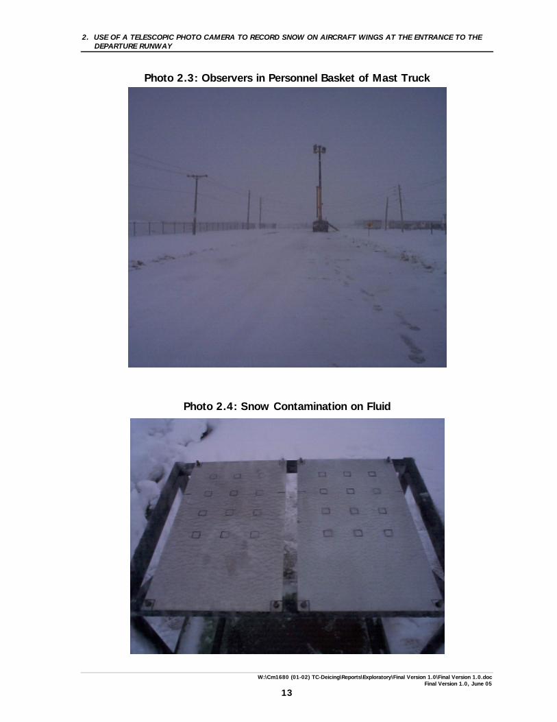
The test consisted of applying fluid on a test plate and then observing the fluid-covered plate through the camera to identify and photograph snow contamination when it appeared. An observer equipped with binoculars was positioned with the photographer on the high-mast platform to assist in the identification of the snow on the plate surfaces. A plate tester positioned at the test stand maintained radio contact with the observer to communicate advice as to when snow failures appeared and how failure progressed on the test surfaces. The plate tester recorded the time when contamination started to appear and its progress over the test plate surface, to serve as a reference comparison for photographic documentation of contamination. Photos were taken during a snowstorm at low visibility. Photo 2.1 shows a two-position test stand, with two plates installed, positioned on the snow-covered roadway near the APS test site. Photo 2.2 shows the personnel basket installed at the end of the mast. Photo 2.3 is a picture of the mast-truck and observers in the personnel basket as seen from the test stand in Run 1 (56 m horizontal distance and 18 m vertical).
2. USE OF A TELESCOPIC PHOTO CAMERA TO RECORD SNOW ON AIRCRAFT WINGS AT THE ENTRANCE TO THE DEPARTURE RUNWAY
W:\Cm1680 (01-02) TC-Deicing\Reports\Exploratory\Final Version 1.0\Final Version 1.0.doc Final Version 1.0, June 05
8
Photo 2.4 shows the “slush-type” of fluid contamination experienced during this test in heavy snow. 2.2.3 Data Forms
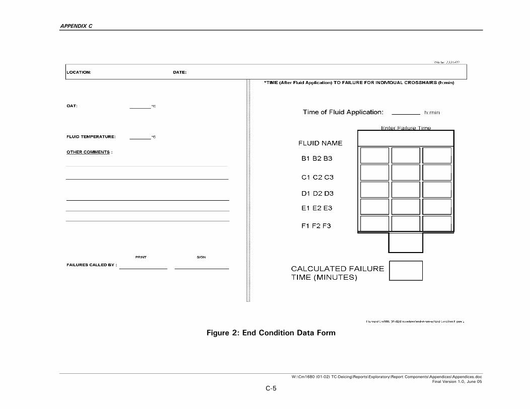
Two data forms were completed by the plate tester. The first form was used to record the details of each test (such as run number, distance from camera to stand, plate position being viewed, fluid type, etc.). The second form was a record of fluid condition on the plate, documenting the start and subsequent progress of snow contamination across the plate. These data forms are included in the test procedure in Appendix C. 2.2.4 Equipment and Fluids
The key equipment used in this test was a 35 mm Nikon camera fitted with a telescopic lens. The camera was installed on a tripod to keep it steady. Other equipment included the high-mast truck with personnel basket, test stand and test plates, and two-way radios. The fluid used for this test was SAE Type IV SPCA AD480 fluid mixed to 50/50 concentration.
2.2.5 Personnel Four APS staff were involved: a photographer and observer positioned in the personnel basket of the high-mast truck, a plate tester and a coordinator.
2.3 Observations The objective of this activity was to examine the capability of the camera equipment to distinguish and photograph snow contamination on a fluid-covered surface from some distance. In Run #1, with the camera located at a 59 m diagonal distance, it was quickly determined that snow accumulations on the fluid-covered test surfaces could not be discerned with the camera equipment. The fluid-covered surfaces simply appeared as grey surfaces. Neither the fluid colour nor snow contamination could be recognized.
2. USE OF A TELESCOPIC PHOTO CAMERA TO RECORD SNOW ON AIRCRAFT WINGS AT THE ENTRANCE TO THE DEPARTURE RUNWAY
W:\Cm1680 (01-02) TC-Deicing\Reports\Exploratory\Final Version 1.0\Final Version 1.0.doc Final Version 1.0, June 05
9
In Run #2, the plate stand was moved closer to the camera, giving a 35 m diagonal distance. Even at this reduced distance, the snow contamination on the fluid-covered surfaces could not be discerned (Photo 2.4). In addition to the long viewing distances involved, the low level of ambient light contributed to the difficulty in seeing the target snow contamination. The tests were conducted during daytime; however, the ambient light level was much reduced with the falling snow. Slight movements of personnel in the bucket tended to cause some swaying of the bucket, which translated into a displacement of the viewing angle large enough for the camera to lose sight of the target. A more stable platform would be required for end-of-runway tests.
2.4 Conclusion The camera equipment planned for documenting snow on wings of departing aircraft proved to be inadequate for the task. The photographer concluded that although a higher power telescopic lens could be used, the low ambient light would still be a problem. As well, the higher power instrument would be more sensitive to any movements of the viewing platform.
10
This page intentionally left blank.
2. USE OF A TELESCOPIC PHOTO CAMERA TO RECORD SNOW ON AIRCRAFT WINGS AT THE ENTRANCE TO THE DEPARTURE RUNWAY
W:\Cm1680 (01-02) TC-Deicing\Reports\Exploratory\Final Version 1.0\Final Version 1.0.doc Final Version 1.0, June 05
11
Photo 2.1: Test Plates for Camera Tests
Photo 2.2: Personnel Basket Installed on Mast
12
This page intentionally left blank.
2. USE OF A TELESCOPIC PHOTO CAMERA TO RECORD SNOW ON AIRCRAFT WINGS AT THE ENTRANCE TO THE DEPARTURE RUNWAY
W:\Cm1680 (01-02) TC-Deicing\Reports\Exploratory\Final Version 1.0\Final Version 1.0.doc Final Version 1.0, June 05
13
Photo 2.3: Observers in Personnel Basket of Mast Truck
Photo 2.4: Snow Contamination on Fluid
14
This page intentionally left blank.
3. HOT WATER TESTS
W:\Cm1680 (01-02) TC-Deicing\Reports\Exploratory\Final Version 1.0\Final Version 1.0.doc Final Version 1.0, June 05
15
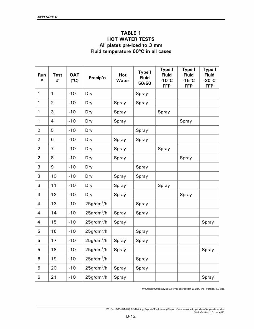
3. HOT WATER TESTS This section discusses the conduct and results of tests examining the use of hot water to remove ice from aircraft surfaces prior to the application of deicing fluids. 3.1 Introduction During the winter of 1998-99, APS examined the weather limits for hot water deicing in a series of laboratory tests. That study (TP 13483E), supported by data from various related tests conducted in previous years, indicated that the ambient temperature limit of -3°C currently recommended for the use of hot water in the SAE Aerospace Recommended Practice ARP4737 (1) could be lowered. Following the January 1998 ice storm in Eastern Canada and the North-Eastern United States, it was reported that the principal agent that had been used to remove ice from aircraft was heated SAE Type I deicing fluid, at standard concentration (50/50 mix). The nature of the ice storm, which lasted for several days, produced a very thick layer of ice on surfaces of aircraft parked for the duration of the storm. As a result of low ambient temperatures, large quantities of glycol were dispensed when the aircraft were eventually deiced. It was proposed that the use of hot water to remove the ice, followed by an application of heated deicing fluid to flush the water away, could have produced the same results at a much lower cost. 3.2 Objectives The objective of this study was to investigate and evaluate, for heavily iced aircraft, the potential amount of Type I fluid that could be saved by preceding the deicing operation with hot water as compared to deicing only with Type I fluid. 3.3 Attempted Tests Tests were conducted in accordance with procedures described at the end of Appendix D, in controlled laboratory conditions at the National Research Council Canada Climatic Engineering Facility. Tests were conducted in conjunction with other tests to develop a Type I fluid protocol.
3. HOT WATER TESTS
W:\Cm1680 (01-02) TC-Deicing\Reports\Exploratory\Final Version 1.0\Final Version 1.0.doc Final Version 1.0, June 05
16
In preparation for these tests, standard aluminum test plates were preconditioned with a layer of ice 2.5 mm (0.1 in.) thick. The ice layer was made by progressively applying a light spray of water from a hand-held spray bottle. Preconditioned plates were mounted on a test stand at a 10º slope. The test consisted of removing the layer of ice with a spray of heated fluid, and measuring the quantity of fluid required to obtain a clean surface. Fluid temperature was 60ºC and ambient temperature was -10ºC. An over-spray of heated Type I fluid was required when heated water was used to clean the surface. The fluid sprayer used to apply the heated water was a unit built by APS for the Hot Water tests conducted during the winter of 1998-99 described in TC report TP 13483E (4), based on a small water-heater tank pressurized with compressed air. This unit contained sufficient water for consecutive tests at the desired temperature. Since only one water heater-type sprayer was available, the heated Type I fluid was applied using a different sprayer. This was a hand-held sprayer that had been fabricated for Deicing Only tests (see TC report TP 13478E (5)), where small quantities of fluid were needed. The sprayer consisted of a short piece of PVC pipe with screw caps at either end. The cap at one end was modified to accept a sprayer nozzle, and a compressed air fitting was installed in the other cap. One cap was removed to pour the heated fluid. The unit was weighed before and after the spray test (Photo 3.1). The two types of sprayers were fitted with the same type of nozzle, and were pre-tested to ensure a common rate of flow and the expulsion of similar spray patterns. Only two tests were attempted, both in precipitation-free (deicing only) conditions. Two test fluids were used: water and SAE Type I ethylene glycol-based fluid at the standard 50/50 concentration. 3.4 Results In an initial test run, the operator sprayed the plate starting at the top edge. At the start, the ice was well adhered to the plate, and cleaning was achieved by melting away the ice. However, as the point of spray application gradually moved down the plate, the temperature of the remainder of the ice-covered plate was raised. An uncontrolled amount of ice then lost its adherence, broke away, and slid off the plate. This affected the quantity of fluid needed to clean the entire surface.
3. HOT WATER TESTS
W:\Cm1680 (01-02) TC-Deicing\Reports\Exploratory\Final Version 1.0\Final Version 1.0.doc Final Version 1.0, June 05
17
Different methods of spray application were tried in an attempt to achieve comparable results, and melting the ice starting at the bottom edge and proceeding up the plate was eventually used for tests. Even with this method, ice broke away under the pressure of the fluid. There was also reduced adhesion of the ice to the heated plate as the spray neared the top edge. A comparison of results for the two tests conducted showed that the fluid quantities used were too different to be realistic. Because the procedure seemed inappropriate and was producing invalid results, the tests were cancelled. One problem with the test approach was that of scale. A small test surface was used to simulate fluid amounts needed to clean a complete wing. Any small deviation in results during the test would be magnified when applied to a full wing. In this case, the uncontrolled area of the plate cleaned by ice sliding away had an exaggerated effect on results. The resulting cleaned area was a much larger proportion of the plate surface than the proportion of a similarly cleaned area of a wing would be when compared to the total wing surface. A second problem was the test method used to remove ice. In a real field operation, ice is typically removed by concentrating the heated fluid in a single spot to melt through to the underlying wing surface. Heat is then propagated into the wing surface underneath the surrounding ice to reduce its adherence and allow the fluid pressure to break it away and flush it off the wing. Since this is very difficult to simulate accurately in a lab, the test method of cleaning the ice by melting was attempted, although it was not representative of field procedures. It is hypothesized that problems would also be encountered in attempts to study differences in fluid quantities by testing on actual aircraft. Subtle and unintentional changes in operator technique would likely result in significant variations in fluid quantities applied. A large number of tests would need to be conducted. 3.5 Recommendations It is recommended that any future efforts to investigate the difference in quantity of hot water, versus Type I fluid, used to deice be limited to a simple analytical approach.
18
This page intentionally left blank.
3. HOT WATER TESTS
W:\Cm1680 (01-02) TC-Deicing\Reports\Exploratory\Final Version 1.0\Final Version 1.0.doc Final Version 1.0, June 05
19
Photo 3.1: Hand-Held Sprayer for Deicing
20
This page intentionally left blank.
4. EXPLORATION OF THE USE OF INFRARED THERMOMETERS FOR ICE DETECTION
W:\Cm1680 (01-02) TC-Deicing\Reports\Exploratory\Final Version 1.0\Final Version 1.0.doc Final Version 1.0, June 05
21
4. EXPLORATION OF THE USE OF INFRARED THERMOMETERS FOR ICE DETECTION
4.1 Objective The objective was to ascertain whether remote infrared (IR) temperature sensors would be a useful addition to the program to be conducted by GlobeGround during the winter of 2001-02 to demonstrate the application of remote ice detection sensors to replace tactile testing. 4.2 Exploratory Tests Exploratory tests were conducted on September 12, 2001, at NRC’s CEF in Ottawa. Tests were conducted on test plates in general accordance with the test plan and procedure dated September 10, 2001, and provided in Appendix E. As these tests were exploratory in nature and were not budgeted, a limited number of tests were carried out at the same time as other tests. Three infrared sensors were tested:
a) Infrared thermometer Raytek (RAYRPM3SZ) designated ARC;
b) Infrared thermometer Minolta/Land (CYCLOPS Mini-laser) designated FAA; and
c) Infrared camera Agema Thermovision 900 designated NRC.
In addition, ACR/YSI surface thermistors, loggers, and a Wahl hand-held digital thermometer were used.
4.3 Data Tests were conducted on standard test plates used for endurance time tests. The test plates were cold-soaked to ambient temperatures of -25ºC and -10ºC. The IR camera was mounted in the chamber (at OAT) with the display in the chamber control room (20°C). The two IR temperature sensors were kept warm and only taken into the cold room when the tests were conducted.
4. EXPLORATION OF THE USE OF INFRARED THERMOMETERS FOR ICE DETECTION
W:\Cm1680 (01-02) TC-Deicing\Reports\Exploratory\Final Version 1.0\Final Version 1.0.doc Final Version 1.0, June 05
22
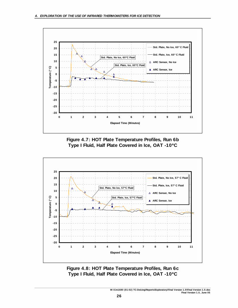
Eight charts (see Figures 4.1 to 4.8) were produced to illustrate the results. The curves presented in each chart represent the temperature readings from the loggers as a function of time. The individual points are readings from one or both of the two sensors used. They are superimposed on the same chart to compare the measurements from each of the sensors. 4.4 Results and Observations Test results were obtained from visual observations and from the analysis of hard data. The results were very encouraging. As observed on the charts (see Figures 4.1 to 4.4), the readings from the sensors and the actual plate temperature were generally similar. The tests demonstrated that at a fixed position, all sensors, thermistors, and the hand-held thermometer were showing very close to equivalent readings. Furthermore, the infrared camera gave a very colourful representation of the plate during spraying. Comparison of the results from both sensors shows that the ARC Sensor appeared to give readings closer to the thermistor readings than the FAA Sensor (see Figures 4.6 and 4.7). The tests proved that, for about 2 to 3 minutes immediately after spraying (see Figures 4.5 to 4.8), there is a significant difference between the curves for a bare plate and an ice-covered plate. The clean surface will show, for a limited period, a positive temperature. On the other hand, a plate with any ice present will show a negative temperature very quickly after application. That means that an observer starting to take measurements right after spray is initiated would have 2 to 3 minutes to discern whether there is ice left on the wing, just by observing the positive and negative temperatures. Using the IR camera, a “shading” effect for Type IV fluid on a contaminated plate was seen. The cold, viscous fluid acted like a blanket; the IR sensors picked up only the fluid surface temperature and, therefore, the presence of ice was undetected. A constant temperature was observed over the entire surface. Finally, it was demonstrated that the distance and angle has an effect on the contamination to be detected; the further away the sensor, the larger the area must be before it is identified. At present, results indicate that detection of contamination can be seen at reasonable operational truck distances.
4. EXPLORATION OF THE USE OF INFRARED THERMOMETERS FOR ICE DETECTION
W:\Cm1680 (01-02) TC-Deicing\Reports\Exploratory\Final Version 1.0\Final Version 1.0.doc Final Version 1.0, June 05
23
Figure 4.1: HOT Plate Temperature Profiles, Run 2 Type I Fluid, No Ice, OAT -23.6ºC
Figure 4.2: HOT Plate Temperature Profiles, Run 2a Type I Fluid, No Ice, OAT -23.6ºC
-30
-25
-20
-15
-10
-5
0
5
10
15
20
25
0 1 2 3 4 5 6 7 8 9 10 11
Elapsed Time (Minutes)
Tem
pera
ture
(°C
)Std. Plate, No Ice, 60°C Fluid
ARC Sensor
-30
-25
-20
-15
-10
-5
0
5
10
15
20
25
0 1 2 3 4 5 6 7 8 9 10 11
Elapsed Time (Minutes)
Tem
pera
ture
(°C
)
Std. Plate, No Ice, 60°C Fluid
ARC Sensor
4. EXPLORATION OF THE USE OF INFRARED THERMOMETERS FOR ICE DETECTION
W:\Cm1680 (01-02) TC-Deicing\Reports\Exploratory\Final Version 1.0\Final Version 1.0.doc Final Version 1.0, June 05
24
Figure 4.3: HOT Plate Temperature Profiles, Run 4 Type I Fluid, Plate Covered in Ice, OAT -23.9ºC
Figure 4.4: HOT Plate Temperature Profiles, Run 4a Type I Fluid, Plate Covered in Ice, OAT -23.9ºC
-30
-25
-20
-15
-10
-5
0
5
10
15
20
25
0 1 2 3 4 5 6 7 8 9 10 11
Elapsed Time (Minutes)
Tem
pera
ture
(°C
)
Std. Plate, Ice, 60°C Fluid
FAA Sensor
-30
-25
-20
-15
-10
-5
0
5
10
15
20
25
0 1 2 3 4 5 6 7 8 9 10 11
Elapsed Time (Minutes)
Tem
pera
ture
(°C
)
Std. Plate, Ice, 60°C Fluid
FAA Sensor
4. EXPLORATION OF THE USE OF INFRARED THERMOMETERS FOR ICE DETECTION
W:\Cm1680 (01-02) TC-Deicing\Reports\Exploratory\Final Version 1.0\Final Version 1.0.doc Final Version 1.0, June 05
25
Figure 4.5: HOT Plate Temperature Profiles, Run 6 Type I Fluid, Half Plate Covered in Ice, OAT -10ºC
Figure 4.6: HOT Plate Temperature Profiles, Run 6a Type I Fluid, Half Plate Covered in Ice, OAT -10ºC
-30
-25
-20
-15
-10
-5
0
5
10
15
20
25
0 1 2 3 4 5 6 7 8 9 10 11
Elapsed Time (Minutes)
Tem
pera
ture
(°C
)Std. Plate, No Ice, 40°C Fluid
Std. Plate, Ice, 40°C Fluid
FAA Sensor, No Ice
FAA Sensor, Ice
ARC Sensor, No Ice
ARC Sensor, Ice
Std. Plate, No Ice, 40ºC Fluid
Std. Plate, Ice, 40ºC Fluid
-30
-25
-20
-15
-10
-5
0
5
10
15
20
25
0 1 2 3 4 5 6 7 8 9 10 11
Elapsed Time (Minutes)
Tem
pera
ture
(°C
)
Std. Plate, No Ice, 60°C Fluid
Std. Plate, Ice, 60°C Fluid
FAA Sensor, No Ice
FAA Sensor, Ice
Std. Plate, No Ice, 60ºC Fluid
Std. Plate, Ice, 60ºC Fluid
4. EXPLORATION OF THE USE OF INFRARED THERMOMETERS FOR ICE DETECTION
W:\Cm1680 (01-02) TC-Deicing\Reports\Exploratory\Final Version 1.0\Final Version 1.0.doc Final Version 1.0, June 05
26
Figure 4.7: HOT Plate Temperature Profiles, Run 6b Type I Fluid, Half Plate Covered in Ice, OAT -10ºC
Figure 4.8: HOT Plate Temperature Profiles, Run 6c Type I Fluid, Half Plate Covered in Ice, OAT -10ºC
-30
-25
-20
-15
-10
-5
0
5
10
15
20
25
0 1 2 3 4 5 6 7 8 9 10 11
Elapsed Time (Minutes)
Tem
pera
ture
(°C
)Std. Plate, No Ice, 60°C Fluid
Std. Plate, Ice, 60°C Fluid
ARC Sensor, No Ice
ARC Sensor, Ice
Std. Plate, No Ice, 60ºC Fluid
Std. Plate, Ice, 60ºC Fluid
-30
-25
-20
-15
-10
-5
0
5
10
15
20
25
0 1 2 3 4 5 6 7 8 9 10 11
Elapsed Time (Minutes)
Tem
pera
ture
(°C
)
Std. Plate, No Ice, 57°C Fluid
Std. Plate, Ice, 57°C Fluid
ARC Sensor, No Ice
ARC Sensor, Ice
Std. Plate, No Ice, 57ºC Fluid
Std. Plate, Ice, 57ºC Fluid
4. EXPLORATION OF THE USE OF INFRARED THERMOMETERS FOR ICE DETECTION
W:\Cm1680 (01-02) TC-Deicing\Reports\Exploratory\Final Version 1.0\Final Version 1.0.doc Final Version 1.0, June 05
27
4.5 Comments Tests conducted before these exploratory tests showed that the infrared thermometers/cameras cannot be used through windows, glass or plastic. The emissivity factors stipulated in the manufacturer tables were incorrect for the type of aluminum plates used. A default factor of 0.95 was used for the tested surfaces and provided accurate results for this application. 4.6 Recommendations Although encouraging conclusions could be drawn from results obtained during these preliminary tests, further tests should be conducted. Below are a few recommendations for future tests:
a) Infrared thermometers/cameras should be tested on a full-scale test wing, where predetermined areas of a test wing are contaminated to determine limits of operation and whether problems encountered by other agencies are repeated. In this controlled experiment, the deicer would be unaware of the exact locations of contamination, and would use infrared thermometers/cameras to find the contaminated area.
b) Determine the range limits of the infrared thermometers/cameras, considering a normal deicing situation.
c) Determine whether sensors can be used in precipitation conditions for Type I anti-icing procedures.
28
This page intentionally left blank.
REFERENCES
W:\Cm1680 (01-02) TC-Deicing\Reports\Exploratory\Final Version 1.0\Final Version 1.0.doc Final Version 1.0, June 05
29
REFERENCES
1. Society of Automotive Engineers (SAE) Aerospace Recommended Practice ARP4737 (Rev. E), Aircraft Deicing/Anti-icing Methods with Fluids, Warrendale, PA, December 2001, 30.
2. Dawson, P., Peters, A., Feasibility of Use of Ice Detection Sensors for
End-of-Runway Wing Checks, APS Aviation Inc., Transportation Development Centre, Montreal, October 1999, TP 13481E, 48.
3. Dawson, P., Hunt, M., Ice Detection Sensor Capabilities for End-of
Runway Wing Checks: Phase 2 Evaluation, APS Aviation Inc., Transportation Development Centre, Montreal, August 2000, TP 13662E (to be published).
4. Dawson, P., Hanna, M., Hot Water Deicing of Aircraft, APS Aviation Inc.,
Transportation Development Centre, Montreal, October 1999, TP 13483E, 92.
5. Dawson, P., Hanna, M., Chaput, M., Peters, A., Blais, N., Aircraft Deicing
Fluid Freeze Point Buffer Requirements for Deicing Only Conditions, APS Aviation Inc., Transportation Development Centre, Montreal, November 1999, TP 13478E, 176.
30
This page intentionally left blank.
APPENDIX A
TERMS OF REFERENCE – PROJECT DESCRIPTION EXCERPTS FROM TRANSPORTATION DEVELOPMENT CENTRE
WORK STATEMENT
APPENDIX A
W:\Cm1680 (01-02) TC-Deicing\Reports\Exploratory\Report Components\Appendices\Appendices.doc Final Version 1.0, June 05
A-1
Work Statement Index This appendix contains excerpts from work statements that relate to the following activities: Use of a Telescopic Photo Camera to Record Snow on Wings at End of Runway Excerpts from both TDC Work Statements DC187 and DC202 are relevant to the reported work. Hot Water Trials The excerpt from TDC Work Statement DC187 is relevant to the work that is being reported. Infra Red The excerpt from TDC Work Statement DC187 is relevant to the work that is being reported.
APPENDIX A
W:\Cm1680 (01-02) TC-Deicing\Reports\Exploratory\Report Components\Appendices\Appendices.doc Final Version 1.0, June 05
A-2
Use of a Telescopic Photo Camera to Record Snow on Wings at End of Runway
5.8 Contamination of Wings at End-of-Runway During the past two winter seasons, TDC conducted an initial series of field trials to study the feasibility of using a remote ground ice detection system (GIDS) to assess ice contamination on aircraft wings just prior to entering the departure runway. The study required scanning of the wing leading edge (as would be seen on an aircraft approaching the sensor position), as well as of the top of the wing (as on an aircraft directly in front of the sensor position). The sensor was positioned to simulate an end-of-runway orientation relative to the aircraft stopping position at the deicing pad. In order to collect further data on wing contamination close to take-off an optical camera will be employed this winter. 5.8.1 Develop a test program; 5.8.2 Meet with Aéroports de Montréal to gain access to the airport, and
meet with AéroMag 2000 to enable acquisition of deicing records; 5.8.3 Assess suitability of photographic equipment to view the wing at the
end of runway; 5.8.4 Conduct a dry run to determine whether the views are adequate from
distances simulating end-of-runway scans; 5.8.5 Conduct trials at the end of runway at Dorval on three occasions
during winter weather operations. The site selected will be determined in consultation with ADM;
5.8.6 Obtain deicing records from AéroMag or by VHF radio; 5.8.7 Analyze results. This will include failure patterns and tracking of the
aircraft and the storm (precipitation rate, temperature) to enable a correlation with holdover times; and
5.8.8 Prepare a presentation and a report.
APPENDIX A
W:\Cm1680 (01-02) TC-Deicing\Reports\Exploratory\Report Components\Appendices\Appendices.doc Final Version 1.0, June 05
A-3
Use of a Telescopic Photo Camera to Record Snow on Wings at End of Runway
Excerpt from
Transportation Development Centre
Work Statement -- DC 202 Aircraft & Anti-Icing Fluid Winter Testing
5.5 Evaluation of Hot Water Deicing During the 1998-99 winter, APS examined weather limits for hot water deicing in a series of laboratory trials. That study, supported by data from various related trials in previous years, indicated that the ambient temperature limit of -3°C currently recommended in SAE Aerospace Recommended Practice ARP4737 could be lowered. Field trials on aircraft that could provide important evidence to authenticate the results of the 1998-99 laboratory trials could not be conducted during the 1999-2000 winter due to lack of suitable weather conditions. The field trials are still an important element of the confirmation and acceptance process, and this task aims at conducting those aircraft trials during the 2000-01 winter season in conjunction with field trials for the Type I protocol. 5.5.1 Conduct trials to confirm the test results observed under laboratory
conditions. Two test sessions on aircraft are proposed in snow conditions. Type I test protocol trials will examine the application of a deicing fluid mixed to the currently approved buffer level and will serve as a reference for the hot water trials.
5.5.2 Collect data in these trials including:
• Type, quantity, and temperature of fluid applied; • Record of weather conditions and precipitation rate; • Time and location for freezing to start to appear on wing
surfaces; • Thickness and roughness of ice formation; • Examination of wing cavities for evidence of ice; • Temperature history of points on the wing surface; • Rate of dilution of deicing fluid on wing surface; and • Photo and videotape records of test set-up and results.
5.5.3 Provide a test team of five members whose responsibilities will include
APPENDIX A
W:\Cm1680 (01-02) TC-Deicing\Reports\Exploratory\Report Components\Appendices\Appendices.doc Final Version 1.0, June 05
A-5
test co-ordination, photo/video, wing observation, and spray co-ordination.
5.5.4 Co-ordinate all test activities, initiating tests in conjunction with NRC
staff based on forecast weather and aircraft availability. 5.5.5 Analyze all results and will document the findings in a final technical
report and in a presentation.
APPENDIX A
W:\Cm1680 (01-02) TC-Deicing\Reports\Exploratory\Report Components\Appendices\Appendices.doc Final Version 1.0, June 05
5.9.2 Infra Red To ascertain whether remote temperature IR sensors would be a useful addition to the program Globe Ground, conduct trials to demonstrate the application of remote ice detection sensors to replace tactile testing.
APPENDIX B
MEMORANDUM ON FIELD TESTS TO DETERMINE EXTENT OF CONTAMINATION
ON DEPARTING AIRCRAFT Winter 2000-01
APPENDIX B
W:\Cm1680 (01-02) TC-Deicing\Reports\Exploratory\Report Components\Appendices\Appendices.doc Final Version 1.0, June 05
B-1
MEMORANDUM ON FIELD TESTS TO DETERMINE EXTENT OF CONTAMINATION
ON DEPARTING AIRCRAFT Winter 2000-2001
1. BACKGROUND
During the winter seasons of 1998-99 and 1999-2000, APS Aviation (APS) studied the feasibility of using a remote ground ice detection system (GIDS) to assess ice contamination on aircraft wings just prior to entering the departure runway. Results of those studies were reported in Transport Canada reports TP 13481E and TP 13662E. Several separate activities with specific objectives were specified within the program, including:
• Examining sensitivity limits of sensor systems; • Developing confidence in ice detection indications with the sensor installed in
typical end-of-runway orientation; and • Examining the feasibility of locating and operating at end-of-runway positions
during live operations.
Test results showed that it is feasible to install and operate a remote ice detection system near the entrance to the departure runway. To succeed in this application, the ice detection sensor must be able to indicate presence of contamination with satisfactory sensitivity regardless of scanning distances and angles, or ambient light conditions.
Determination of the sensitivity at which the sensors should operate is an unanswered question. Sensitivity to presence of frozen contamination refers to the minimum depth of contamination and minimum size of contaminated area that is discernible. Setting the sensitivity level of ice detection sensors too low, indicating minute amounts of contamination considerably below that where flight performance is affected, would result in many unnecessary decisions to return for re-spray. As well as severely degrading scheduled operations, this would promote a loss of confidence in the system.
Efforts to develop minimum performance specifications for ground ice detection systems, under the auspices of the European Organization for Civil Aviation Equipment (EUROCAE) with international industry involvement, settled on a detection threshold of 0.5 mm thickness of ice or peak frost height, continuously distributed over an area of 315 cm2. These levels were selected for the purpose of testing the instruments in the absence of knowledge-based guidelines for acceptable levels of frozen contamination.
In defining an appropriate level of sensitivity for ice detector system operations, it would be constructive to understand the current situation regarding actual contamination on aircraft wings at take-off. Currently there is no scientific database
APPENDIX B
W:\Cm1680 (01-02) TC-Deicing\Reports\Exploratory\Report Components\Appendices\Appendices.doc Final Version 1.0, June 05
B-2
documenting the condition of aircraft wings departing during snow or freezing precipitation. 2. OBJECTIVE This project addressed the following objective:
• To document the extent that contamination exists on wings of aircraft just prior to entering the departure runway during snow conditions.
This memorandum is the sole report for this study.
3. PREPARATION FOR TESTS To satisfy the goal of this study, the test team needed to be located near a runway used for departures during snowstorms, with the observer positioned sufficiently close to the aircraft taxi-line and high enough to enable viewing and photographing of any snow on the wing surface. To satisfy this requirement, a meeting was held with Dorval Airport authorities (January 10, 2001) to agree on test sites and test procedures. At this meeting, a location on the west side of the taxiway hold area for runway 06R was selected as offering the best opportunity for successful viewing during snow conditions. This location (Test Site 1 on the attached map) placed the test set-up at a 40 m distance from the taxiway guideline, and opposite the wingtip of holding aircraft. A second location (Test Site 2) was selected for use in the event that weather conditions should make Test Site 1 unusable. Test Site 2 was located on the east side of the hold area, and had the same taxiway guideline separation distance. These sites were subsequently approved for use by Transport Canada when 06R was used for takeoff and 06L was used for landing. The agreed procedures allowed positioning of a high boom vehicle at the test site. The observer/photographer was positioned in a basket with the boom extended as high as 18 m (60 ft.). The vehicle was able to lower the boom from 18 m to its rest position at 3.6 m in less than one minute. An alert procedure was put in place whereby APS contacted a designated staff member of the airport authority prior to each test session. Airport security agents were contracted to accompany the test team for each session. These agents maintained radio contact with the tower. The two brief test sessions identified some needed changes to procedures and camera equipment:
• Ability to zoom in on wing area, confirmed by ability to identify small wing detail such as rivets; and
APPENDIX B
W:\Cm1680 (01-02) TC-Deicing\Reports\Exploratory\Report Components\Appendices\Appendices.doc Final Version 1.0, June 05
B-3
• Presence of a second observer in the bucket, equipped with a telescope or binoculars, to provide needed assistance to the photographer regarding location of contamination. This observer could record wing condition and contamination location on a data form or voice recorder.
4. ATTEMPTS TO RECORD WING CONTAMINATION Tests were attempted on two occasions – February 02 and 05, 2001. APS personnel monitored forecasted weather and obtained clearance for testing from the designated staff at Aéroports de Montréal, as agreed. The February 02 test provided an opportunity to check out equipment and procedures. The boom truck and basket set-up was found to be suitable for the job. The snowfall ended by the time the location was verified and the unit set up, so there was not a good opportunity to validate the camera capabilities. For the February 05 test, four aircraft were examined during snowfall. Following that, the test team was advised that 06L was being closed for cleaning, and that landings would be moved to 06R. The team was advised that they could not stay in place when landings were in progress on 06R. Additionally, testing was not allowed during moderate to heavy snow condition thereby severely reducing the likelihood of success of the study. Thus the routine became:
• When 06L was being cleared, landings were scheduled for 06R and the test site was unavailable;
• When 06R was being cleared, there were no departures to observe; • Typically in an ongoing snowstorm, the cleaners alternate between runways;
and • No testing was allowed during moderate to heavy snow conditions.
The only opportunity remaining for testing in snowfall was during early morning departures. Usually 06R is readied for these, and with any queuing, there could be an opportunity to view some wings. Weather forecasts were monitored for such an opportunity for several weeks following, but without success. Planning for testing on early morning departures involves many uncertainties as the decision to proceed (involving arrangements for security, high boom truck and staff) must be taken prior to the end of the previous working day.
5. NEEDED ACTION TO COMPLETE THE PROJECT The alternative to limiting tests to early morning departures is to obtain permission to remain at Test Site 1 when 06R is used for landings, with a procedure that
APPENDIX B
W:\Cm1680 (01-02) TC-Deicing\Reports\Exploratory\Report Components\Appendices\Appendices.doc Final Version 1.0, June 05
B-4
requires the mast to be lowered when aircraft are landing. This would require advice from the tower to the test site when landings are in process. Local authorities are unable to grant this approval, and a meeting to seek approval is required with Transport Canada headquarter authorities. Attached: Procedure for Field Trials to Determine Extent of Contamination on Departing Aircraft.
APPENDIX B
W:\Cm1680 (01-02) TC-Deicing\Reports\Exploratory\Report Components\Appendices\Appendices.doc Final Version 1.0, June 05
B-5
B-6
This page intentionally left blank.
BM3833.001
EXPERIMENTAL PROGRAM FIELD TRIALS TO DETERMINE EXTENT OF CONTAMINATION
ON DEPARTING AIRCRAFT
Winter 2000-2001
Prepared for
Transportation Development Centre Transport Canada
Prepared by: Peter Dawson
Reviewed by: John D’Avirro
November 17, 2000 Version 1.1
Editorial Revision October 5, 2004
Version 1.2
APPENDIX B
W:\Cm1680 (01-02) TC-Deicing\Reports\Exploratory\Report Components\Appendices\Appendices.doc Final Version 1.0, June 05
B-8
EXPERIMENTAL PROGRAM FIELD TRIALS TO DETERMINE EXTENT OF CONTAMINATION
ON DEPARTING AIRCRAFT Winter 2000-2001
During the winter seasons of 1998-99 and 1999-2000, APS Aviation (APS) embarked upon a program to study the feasibility of using a remote ground ice detection system (GIDS) to assess ice contamination on aircraft wings just prior to entering the departure runway. Several separate activities with specific objectives were identified within the program. These included:
• Examining sensitivity limits of sensor systems; • Developing confidence in ice detection indications with the sensor installed in
typical end-of-runway orientation; and • Examining the feasibility of locating and operating at end-of-runway positions
during live operations.
Those trials showed that it is feasible to install and operate a remote ice detection system near the entrance to the departure runway. To succeed in this application, the ice detection sensor must satisfy some specific needs related to scanning distances and angles, and lighting. The sensitivity of indications of contamination must be constant regardless of these parameters. These challenges have been passed on to the sensor manufacturers for their consideration. Determination of the sensitivity at which the sensors should operate is an unanswered question. Setting the sensitivity level of ice detection sensors to indicate a minute amount of contamination (considerably below that where flight performance is affected) would result in many decisions to return the aircraft for re-spray, unnecessarily. As well as severely degrading scheduled operations, this would promote a loss of confidence in the system. In the process of defining the level of sensitivity at which the ice detector systems should operate, it would be useful to understand the current situation. Currently there is no scientific database documenting the condition of aircraft wings actually departing during snow or freezing precipitation. Guidelines to pilots on the expected endurance times of applied anti-icing fluids (fluid holdover times or HOT) incorporate a margin of safety by basing those time guidelines on the build-up of levels of contamination that are less than those levels that would result in adherence to the wing surface (which would affect wing aerodynamics and flight performance). In this study, APS will develop procedures and conduct activities to document the condition of wings just prior to departure during snowfall.
APPENDIX B
W:\Cm1680 (01-02) TC-Deicing\Reports\Exploratory\Report Components\Appendices\Appendices.doc Final Version 1.0, June 05
B-9
This document provides the detailed procedures and equipment required by APS to support these trials. 1. OBJECTIVES This project addresses the following objective:
• To document the extent that contamination exists on wings of aircraft just prior to entering the departure runway during snow conditions.
2. TEST REQUIREMENTS To satisfy the goal of this study, the test team must be located near a runway used for departures during snowstorms. The observer must be positioned sufficiently close to the aircraft taxi-line and high enough to enable viewing and photography of the wing surface. The study will be conducted during daytime to avoid the need to direct artificial lighting at the aircraft. The desired location of the observation team is similar to that approved for positioning the ice detection sensor. The process used to determine and approve locations for the scanner will be followed in this study. The test team will first identify the photographic and visual aid equipment suitable for the purpose. The performance of the equipment in assisting an observer to identify snow contamination will determine the desired distances and heights for end-of-runway positioning. The test procedure will be developed with the participation of appropriate staff at Dorval Airport and other regulatory authorities. 2.1 Preparation Preparation activities for operational trials (three sessions) will include:
• identifying equipment to support the study, including camera and visual aids, and equipment for positioning the camera (and observer) at the desired orientation to the aircraft;
• conducting a dry run during December 2000 using a simulated wing surface (wing section or aluminum plate) to determine effective distance and height for observing;
• determining test locations with airport authorities;
APPENDIX B
W:\Cm1680 (01-02) TC-Deicing\Reports\Exploratory\Report Components\Appendices\Appendices.doc Final Version 1.0, June 05
B-10
• developing operational procedures to support the trials with airport authorities;
• developing a procedure to collect deicing information specific to observed aircraft from the deicing centre;
• developing test procedures with detailed responsibilities for all participants, including control of the confidential data gathered on wing condition; and
• notification to all concerned in the project, including aircraft operators, that wing observation activities will be taking place.
2.2 Conduct of Trials APS personnel will monitor forecasted weather and initiate documentation trials based on suitable conditions. Contacts at Transport Canada’s Transportation Development Centre, Aéroports de Montréal and NAV CANADA will be advised when tests are planned. Trials during actual operations will involve positioning the observation vehicle at a location beside the taxiway at the approved location. As aircraft taxi past the observation position, the observer will examine the wing on the near side to identify any evidence of contamination. Any evidence of contamination will be photographed. Aircraft identification will be recorded for each aircraft examined, whether or not contamination was identified. At the end of each trial session, the deicing history of each examined aircraft will be retrieved from the Central Deicing Facility, to be incorporated into the data analysis. There will be no communication of results during the course of the trials. Weather conditions will be recorded on an ongoing basis. At least three trial sessions during periods of snow or freezing precipitation will be attempted. Complete photo and video records of test set-up will be maintained.
3. EQUIPMENT
A list of test equipment is included in Attachment 1.
4. PERSONNEL
It is anticipated that a team of two APS staff will be required to conduct these trials. Descriptions of responsibilities and duties of each team member are given in Attachment 2.
APPENDIX B
W:\Cm1680 (01-02) TC-Deicing\Reports\Exploratory\Report Components\Appendices\Appendices.doc Final Version 1.0, June 05
B-11
A security escort will be required. An operator for the high-lift vehicle will be required. 5. DATA FORMS
The following data forms will be used: Figure 1 RECORD OF OBSERVED AIRCRAFT Figure 2 DEICING HISTORY FOR AIRCRAFT CONTAMINATION TRIALS
M:\Groups\Cm1680(exBM3833)\Procedures\Contamination Of Wings At End-Of-Runway\Version1.0\Version 1_1.Doc
APPENDIX B
W:\Cm1680 (01-02) TC-Deicing\Reports\Exploratory\Report Components\Appendices\Appendices.doc Final Version 1.0, June 05
B-12
ATTACHMENT 1
EQUIPMENT CHECKLIST
TEST EQUIPMENT RESPONSIBLE STATUS
High-lift vehicle with enclosed personnel basket and operator
Personnel van
Still camera and film
Video camera and tape
Tape recorder
Binoculars
Telescope
Security escort
Security passes
Cell phones
2-way radios
Data forms
M:\Groups\Cm1680(exBM3833)\Procedures\Contamination Of Wings At End-Of-Runway\Version1.0\Version 1_1.Doc
APPENDIX B
W:\Cm1680 (01-02) TC-Deicing\Reports\Exploratory\Report Components\Appendices\Appendices.doc Final Version 1.0, June 05
B-13
ATTACHMENT 2
RESPONSIBILITIES / DUTIES OF TEST PERSONNEL Team Leader: • Monitor weather forecasts and initiate trials • Advise contact at Aéroports de Montréal of expected trials • Advise AéroMag 2000 • Arrange for high-lift vehicle • Advise security contract • Advise test staff • Retrieve data on deicing activity from AéroMag 2000 Photographer: • Photograph and videotape test set-up • Positioned in the high-lift personnel bucket, examine and photograph the
near wing of departing aircraft • Tape record identification information of aircraft being examined and a
description of any contamination seen on the wing
M:\Groups\Cm1680(exBM3833)\Procedures\Contamination Of Wings At End-Of-Runway\Version1.0\Version 1_1.Doc
APPENDIX B
W:\Cm1680 (01-02) TC-Deicing\Reports\Exploratory\Report Components\Appendices\Appendices.doc Final Version 1.0, June 05
B-14
FIGURE 1
RECORD OF OBSERVED AIRCRAFT Montreal International Airport, Dorval Date: _________ Runway Location: ____________ Observer: ___________________________ AIRCRAFT
TYPE OPERATOR FIN # TIME WING CONDITION
M:\Groups\Cm1680(exBM3833)\Procedures\Contamination Of Wings At End-Of-Runway\Version1.0\Version 1_1.Doc
APPENDIX B
W:\Cm1680 (01-02) TC-Deicing\Reports\Exploratory\Report Components\Appendices\Appendices.doc Final Version 1.0, June 05
B-15
FIGURE 2
DEICING HISTORY FOR AIRCRAFT CONTAMINATION TRIALS
Montreal International Airport, Dorval Date: _________
AIRCRAFT TYPE AIRLINE FIN # TIME FLIGHT
# FLUID
TYPE(S) START OF
HOT
REASON FOR
DEICING
M:\Groups\Cm1680(exBM3833)\Procedures\Contamination Of Wings At End-Of-Runway\Version1.0\Version 1_1.Doc
B-16
This page intentionally left blank.
APPENDIX C
EXPERIMENTAL PROGRAM FIELD TESTS TO DETERMINE THE EXTENT OF CONTAMINATION
ON DEPARTING AIRCRAFT
CM1680.001
EXPERIMENTAL PROGRAM USE OF A TELESCOPIC PHOTO CAMERA TO RECORD SNOW
ON WINGS AT END-OF-RUNWAY
Winter 2001/2002
Prepared for
Transportation Development Centre Transport Canada
Prepared by: Peter Dawson
Reviewed by: John D’Avirro
February 5, 2002 Version 1.0
Editorial Revision October 5, 2004
Version 1.2
APPENDIX C
W:\Cm1680 (01-02) TC-Deicing\Reports\Exploratory\Report Components\Appendices\Appendices.doc Final Version 1.0, June 05
C-1
1. BACKGROUND A study of the feasibility of using a remote ground ice detection system to assess ice contamination on aircraft wings showed that it is feasible to install and operate a remote ice detection system near the entrance to the departure runway. To succeed in this application, the ice detection sensor must be able to indicate presence of contamination with satisfactory sensitivity regardless of scanning distances and angles, or ambient light conditions. Determination of the sensitivity at which the sensors should operate is an unanswered question. Setting the sensitivity level of ice detection sensors too low, indicating minute amounts of contamination considerably below that where flight performance is affected, would result in many unnecessary decisions to return for re-spray. As well as severely degrading scheduled operations, this would promote a loss of confidence in the system. Efforts to develop minimum performance specifications for ground ice detection systems settled on a detection threshold of 0.5 mm thickness of ice or peak frost height, continuously distributed over an area of 315 cm2. These levels were selected for the purpose of testing the instruments in the absence of knowledge-based guidelines for acceptable levels of frozen contamination. In defining an appropriate level of sensitivity for ice detector system operations, it would be constructive to understand the current situation regarding actual contamination on aircraft wings at take-off. Currently there is no scientific database documenting the condition of aircraft wings departing during snow or freezing precipitation. An initial attempt was made in the winter season 2000-01 to document the extent that contamination exists on wings of aircraft just prior to entering the departure runway during snow conditions. This attempt met with difficulties in gaining clearance to position a test team with camera equipment at an appropriate site near the departure runway. Before expending considerable effort in search of such an approval, it was decided to first ensure that the camera equipment planned for observing aircraft wings is capable of discerning and recording snow at the distances involved.
2. OBJECTIVES The objective of this procedure is to examine the ability of an optical camera fitted with a telescopic lens to discern and photograph snow on fluid-covered surfaces at distances and viewing angles that would be experienced when observing wings on aircraft holding for departure clearance. In parallel with the examination of the camera performance, (subject to Goodrich approval) some scans will be conducted with a Goodrich ice detection camera to
APPENDIX C
W:\Cm1680 (01-02) TC-Deicing\Reports\Exploratory\Report Components\Appendices\Appendices.doc Final Version 1.0, June 05
C-2
gather more information on its ice detection capabilities at test distances and viewing angles. To achieve this objective, the cameras will be installed on a platform on a high-mast vehicle and used to scan failed fluid on test plates at the APS test site at Dorval Airport. If possible, the test will be conducted in conjunction with scheduled fluid endurance trials, otherwise a dedicated test stand will be used for these trials.
3. PROCEDURE/TEST REQUIREMENTS In preparation for test, the assigned photographer will become familiar with use of the camera and telescopic lens, and ensure proper functioning. The camera must record time stamps on each image. Arrangements will be made with an equipment company to enable use on short notice (when a snowstorm is forecast) of a high-mast truck with a personnel platform installed. The test date will be based on forecast of a snowstorm. On the day of test, the mast truck will be parked on the roadway near the APS trailer. The Goodrich scanner and required cabling will be installed on the mast platform. Ice-detection images will be recorded using a VCR located in the site trailer, cabled to the camera. The camera time stamp, the Goodrich system clock and tester watches will be synchronized. A test stand will be positioned with the 10º slope toward the camera position. Four standard aluminium test plates will be mounted on the stand, and treated with fluid. Both Type IV and Type I fluids will be used. Photo camera tests will be conducted from a position giving a diagonal distance of 45 m from camera to stand (41 m horizontal X 18 m vertical), representing the most recent test set-up at the hold-point of runway 06R. The sensor camera will not be used from this position due to cable length limitations. A spotter with binoculars will also be in the high-mast platform to assist the photographer in identifying the snow failures on the test plate. For tests using the ice detection sensor, the high-mast platform will be positioned at a horizontal distance of 26 m and height of 18 m, which is a typical orientation for scanning a B-737 aircraft at an end-of-runway location. This position is compatible with sensor cable lengths. The photographer and a test coordinator positioned at the test stand will be in radio contact to enable advice to be passed to the photographer as snow failures appear and progress on the surfaces. The photographer will view and photograph any
APPENDIX C
W:\Cm1680 (01-02) TC-Deicing\Reports\Exploratory\Report Components\Appendices\Appendices.doc Final Version 1.0, June 05
C-3
snow on the test plate surfaces that is evident with the telescopic-camera. The test coordinator will maintain a record (Figure 1) of which test surfaces are being photographed, with time notations, and will note advice from the photographer as to whether the camera is discerning the snow contamination in the failed fluid. As well, the coordinator at the stand will record the current extent of fluid failure on a Fluid End Condition Data Form (Figure 2). For ice-detection sensor tests, the photographer will periodically scan the test surface being observed with the sensor, at times when photos are taken with the optical camera.
4. EQUIPMENT AND FLUIDS 4.1 Equipment
• A high-mast truck with platform installed • Optical camera with telescope lens • Walkie-talkie radios • Goodrich camera, with cabling for high mast and VCR • Type I and type IV fluid • Data forms
4.2 Fluids Any Type I and IV fluids that are available will be used.
5. PERSONNEL Three APS staff:
• Photographer • Coordinator at the test stand • Observer at monitor for Goodrich sensor, ensuring images recorded on VCR
6. DATA FORMS Figure 1 Data Form for Recording Snow on Wings at End-of-Runway
with a Telescopic Photo Camera
Figure 2 Fluid End Condition Data Form
APPENDIX C
W:\Cm1680 (01-02) TC-Deicing\Reports\Exploratory\Report Components\Appendices\Appendices.doc Final Version 1.0, June 05
C-4
Distance From
Camera To Stand Fluid
Endurance Trial
Run # horizontal height
Plate PositionBeing
Viewed
Fluid Type
Time of
Photo
Sensor Scan? Y or N
Photographer comments
Figure 1: Data Form for Use of a Telescopic Photo Camera to Record Snow on Wings at End-of-Runway
APPENDIX C
W:\Cm1680 (01-02) TC-Deicing\Reports\Exploratory\Report Components\Appendices\Appendices.doc Final Version 1.0, June 05
C-5
Figure 2: End Condition Data Form
C-6
This page intentionally left blank.
APPENDIX D
MEMORANDUM ON HOT WATER TRIALS
CM1680
MEMORANDUM ON HOT WATER TRIALS
Winter 2000-2001
Prepared for
Transportation Development Centre
On behalf of Civil Aviation
Transport Canada
and
The Federal Aviation Administration William J. Hughes Technical Center
Prepared by: Peter Dawson
Reviewed by: John D’Avirro
August 6, 2001 Final Version 1.0
Editorial Revision October 5, 2004
Version 1.1
APPENDIX D
W:\Cm1680 (01-02) TC-Deicing\Reports\Exploratory\Report Components\Appendices\Appendices.doc Final Version 1.0, June 05
D-1
HOT WATER TRIALS 1. BACKGROUND Following the January 1998 ice storm in Eastern Canada and the Northeastern United States, it was reported that the principal agent that had been used for removing ice from aircraft was heated SAE Type I deicing fluid at standard strength (50/50 mix). The nature of the ice storm, which lasted for several days, produced a very thick layer of ice on surfaces of aircraft parked for the duration of the storm. As a result, large quantities of glycol were dispensed when the aircraft were eventually deiced. It has been proposed that the use of hot water to remove the ice, followed by an application of heated deicing fluid to flush the water away, could have produced the same results at a much lower cost. 2. OBJECTIVES
The objective of this study was to investigate and evaluate, for heavily iced aircraft, the potential amount of Type I fluid that could be saved by preceding the deicing operation with hot water. 3. ATTEMPTED TESTS Tests were conducted in accordance with the approved procedures (attached), in controlled laboratory conditions at the National Research Council Canada (NRC) Climatic Engineering Facility (CEF). Tests were conducted in conjunction with Type I fluid protocol development tests. In preparation for tests, standard aluminium test plates were preconditioned with a layer of ice 2.5 mm (0.1 in.) thick. The ice layer was made by progressively applying a light spray of water from a hand-held spray bottle. Preconditioned plates were mounted at a 10º slope on a test stand. The test consisted of removing the layer of ice with a spray of heated fluid, and measuring the quantity of fluid required to obtain a clean surface. Fluid temperature was 60ºC. Ambient temperature was -10ºC. An over-spray of heated Type I fluid was required when heated water was used to clean the surface. The fluid sprayer used to apply the heated water was a unit built by APS for the Hot Water trials conducted in winter 1998-99, based on a small water-heater tank pressurized with compressed air. This unit maintained sufficient water for consecutive tests at the desired temperature.
APPENDIX D
W:\Cm1680 (01-02) TC-Deicing\Reports\Exploratory\Report Components\Appendices\Appendices.doc Final Version 1.0, June 05
D-2
Because only one water-heater type sprayer was available, the heated Type I fluid was applied using a different sprayer. This was a hand-held sprayer that had been fabricated for deicing only trials, where small quantities of fluid were needed. The sprayer consisted of a short piece of PVC pipe with screw caps at either end. The cap at one end was modified to accept a sprayer nozzle, and a compressed air fitting was installed in the other cap. One cap was removed to pour the heated fluid. The unit was weighed before and after the spray test. The two types of sprayers were fitted with the same type of nozzle and were pre-tested to ensure a common rate of flow and similar spray patterns were produced. Only two tests were attempted, both in no-precipitation (deicing only) conditions. Water and SAE Type I ethylene glycol-based fluid at standard 50/50 strength were the test fluids.
4. RESULTS In an initial test run, the operator cleaned the plate starting at the top edge. At the start the ice was well adhered to the plate, and cleaning was achieved via melting away the ice. However, as the point of spray application gradually moved down the plate, the temperature of the remainder of the ice-covered plate was raised. An uncontrolled amount of ice then lost its adherence, broke away, and slid off the plate. This affected the quantity of fluid needed to clean the entire surface. Different methods of spray application were tried in an attempt to achieve comparable results, and melting the ice starting at the bottom edge and proceeding up the plate was eventually used for tests. Even this method experienced ice breaking away with fluid pressure and reduced adhesion to the heated plate, as the spray neared the top edge. A comparison of results for the two tests conducted showed that fluid quantities were too different to be realistic. The tests were cancelled at that time, as the procedure was seen to be inappropriate. One problem with the test approach was that of scale. The small test surface is being used to simulate fluid amounts needed to clean a complete wing. Any small deviation in results during the test is magnified when applied to a full wing. In this case, the uncontrolled area of the plate cleaned by ice sliding away had an exaggerated effect on results. A second problem was the test method used to remove ice. In a real field operation, ice is typically removed by concentrating the heated fluid at a single spot to melt through to the underlying wing surface. Heat is then propagated into the wing surface underneath the surrounding ice to reduce its adherence and allow the fluid pressure to break it away and flush it off the wing. Since this is very difficult to simulate accurately in a lab, the trial method of cleaning the ice by melting was
APPENDIX D
W:\Cm1680 (01-02) TC-Deicing\Reports\Exploratory\Report Components\Appendices\Appendices.doc Final Version 1.0, June 05
D-3
attempted, although not representative of field procedures. It is believed that attempts to study differences in fluid quantities by testing on actual aircraft would also encounter problems. Subtle and unintentional changes in operator technique would likely result in significant variances in fluid quantities applied, requiring a large number of tests to overcome. It is recommended that any future efforts to investigate the difference in quantity of water, versus Type I fluid, used to deice be limited to an analytical approach. Attached: Procedure for Hot Water Trials
M\Groups\CM(exBM3833)\reports\Hot Water\Final Version 1.0.doc
D-4
This page intentionally left blank.
D-5
PROCEDURE
D-6
This page intentionally left blank.
CM1680
HOT WATER TRIALS
Winter 2000-2001
Prepared for
Transportation Development Centre Transport Canada
Prepared by: Peter Dawson
Reviewed by: John D’Avirro
March 7, 2001 Version 1.0
Editorial Revision October 5, 2004
Version 1.1
D-8
This page intentionally left blank.
APPENDIX D
W:\Cm1680 (01-02) TC-Deicing\Reports\Exploratory\Report Components\Appendices\Appendices.doc Final Version 1.0, June 05
D-9
HOT WATER TRIALS 1. OBJECTIVES The objectives of this procedure are to investigate and evaluate, for heavily iced aircraft, the potential amount of Type I fluid that could be saved by preceding the deicing operation with hot water. The investigation is to examine the potential both under “deicing only” conditions and during ongoing precipitation. These tests will be conducted in controlled laboratory conditions, in the National Research Council Canada (NRC) Climatic Engineering Facility (CEF). 2. BACKGROUND Following the January 1998 ice storm in Eastern Canada and the Northeastern United States, it was reported that the principal agent used for removing ice from aircraft had been heated SAE Type I deicing fluid at standard strength (50/50 mix). The nature of this ice storm, which lasted for several days, produced a very thick layer of ice on surfaces of aircraft parked for the duration of the storm. As a result, large quantities of glycol were dispensed when the aircraft were eventually deiced. It is proposed that the use of hot water to remove the large part of the ice, followed by an application of deicing fluid, could have produced the same results at a much lower cost. 3. TEST REQUIREMENTS Tests will be scheduled at the NRC CEF in conjunction with tests related to Type I fluid protocol development. Tests will be conducted both in dry (deicing only) conditions and under freezing rain at 25g/dm2/h. An ambient temperature of -10ºC will be established for all trials. Tests will be conducted on standard aluminium test plates, preconditioned with a layer of ice 2.5 mm (0.1 in.) thick. For both types of trials (deicing only and precipitation), the quantity of initial fluid and of over-spray will be recorded. The progressive freeze point of the final fluid on the plate will be measured. Fluids will be applied at a temperature of 60ºC.
APPENDIX D
W:\Cm1680 (01-02) TC-Deicing\Reports\Exploratory\Report Components\Appendices\Appendices.doc Final Version 1.0, June 05
D-10
3.1 Trials in deicing only conditions
For the deicing only trials, the treatment will consist of:
• an application of standard strength fluid; • an application of hot water followed by an over-spray of standard strength
(50/50) Type I fluid; • an application of hot water followed by an over-spray of Type I fluid mixed
to a freeze point of -10ºC; and • an application of hot water followed by an over-spray of Type I fluid mixed
to a freeze point of -15ºC.
The over-spray will be applied 3 minutes after the plates have been cleaned.
3.2 Trials in ongoing precipitation conditions
These trials will be conducted under freezing rain at 25g/dm2/h. For these trials, the treatment will consist of:
• an application of standard strength fluid; • an application of hot water followed by an over-spray of standard strength
(50/50) Type I fluid; and • an application of hot water followed by an over-spray of Type I fluid mixed
to a freeze point of -20ºC. 4. EQUIPMENT AND FLUIDS 4.1 Equipment See list in Attachment 1. 4.2 Fluids SAE Type I ethylene glycol-based fluid at standard 50/50 strength and diluted to a variety of freeze points as shown in the test matrix, heated to 60ºC.
Water heated to 60ºC.
APPENDIX D
W:\Cm1680 (01-02) TC-Deicing\Reports\Exploratory\Report Components\Appendices\Appendices.doc Final Version 1.0, June 05
D-11
5. PERSONNEL Five APS personnel are required for these tests:
• Coordinator • Fluid preparation and sprayer (manager and assistant) • Plate preparation • Photo/Video
6. DATA FORMS
Figure 1 Data Form for Hot Water Trials Figure 2 Meteo Form
M\Groups\CM(exBM3833)\Procedures\Hot Water\Final Version 1.0.doc
APPENDIX D
W:\Cm1680 (01-02) TC-Deicing\Reports\Exploratory\Report Components\Appendices\Appendices.doc Final Version 1.0, June 05
D-12
TABLE 1 HOT WATER TESTS
All plates pre-iced to 3 mm Fluid temperature 60ºC in all cases
Run #
Test #
OAT (ºC) Precip’n Hot
Water
Type I Fluid 50/50
Type I Fluid -10ºC FFP
Type I Fluid -15ºC FFP
Type I Fluid -20ºC FFP
1 1 -10 Dry Spray
1 2 -10 Dry Spray Spray
1 3 -10 Dry Spray Spray
1 4 -10 Dry Spray Spray
2 5 -10 Dry Spray
2 6 -10 Dry Spray Spray
2 7 -10 Dry Spray Spray
2 8 -10 Dry Spray Spray
3 9 -10 Dry Spray
3 10 -10 Dry Spray Spray
3 11 -10 Dry Spray Spray
3 12 -10 Dry Spray Spray
4 13 -10 25g/dm2/h Spray
4 14 -10 25g/dm2/h Spray Spray
4 15 -10 25g/dm2/h Spray Spray
5 16 -10 25g/dm2/h Spray
5 17 -10 25g/dm2/h Spray Spray
5 18 -10 25g/dm2/h Spray Spray
6 19 -10 25g/dm2/h Spray
6 20 -10 25g/dm2/h Spray Spray
6 21 -10 25g/dm2/h Spray Spray
M\Groups\CM(exBM3833)\Procedures\Hot Water\Final Version 1.0.doc
APPENDIX D
W:\Cm1680 (01-02) TC-Deicing\Reports\Exploratory\Report Components\Appendices\Appendices.doc Final Version 1.0, June 05
D-13
ATTACHMENT 1
EQUIPMENT CHECKLIST HOT WATER TRIALS
TEST EQUIPMENT RESPONSIBLE STATUS
Data forms
Water heater compressed air sprayer (2)
Hand-held spray units (3)
Scale for weighing hand-held spray units
Containers for fluid preparation
Brixometers
Hot plates
Fluid temperature probe with spare batteries
Isopropyl alcohol and wiping rags
Garden sprayer for making ice on plates
Stand for six test surfaces
Standard test plates (8)
Rate pans
Rate station
Clipboards and pencils
Still camera
Video camera
Extension cords
Clipboards and pencils
Large clock
M\Groups\CM(exBM3833)\Procedures\Hot Water\Final Version 1.0.doc
APPENDIX D
W:\Cm1680 (01-02) TC-Deicing\Reports\Exploratory\Report Components\Appendices\Appendices.doc Final Version 1.0, June 05
D-14
ATTACHMENT 2
PERSONNEL ASSIGNMENT Coordinator
• Briefs all involved on test procedure and tasks • Determines any changes to test procedure as tests progress • Ensures that all data are collected and saved
Fluid Preparation and Sprayer; Manager and Assistant
• Prepares fluids to required concentration and temperature • Ensures data forms are completed • Applies fluid to tests surfaces • Measures and records quantity of fluid applied
Test Surface Preparation
• Builds ice film on plates in preparation for tests • Assists in fluid application as needed
Photo/Video
• Videotapes and photographs all test set-up • Videotapes fluid spray
M\Groups\CM(exBM3833)\Procedures\Hot Water\Final Version 1.0.doc
APPENDIX D
W:\Cm1680 (01-02) TC-Deicing\Reports\Exploratory\Report Components\Appendices\Appendices.doc Final Version 1.0, June 05
PRINT SIGN WRITTEN & PERFORMED BY : __________________ __________________ PHOTO BY: __________________ __________________ TEST SITE LEADER: __________________ __________________
EXPERIMENTAL PROGRAM PRELIMINARY EVALUATION OF INFRARED THERMOMETERS TO ASSIST
IN IDENTIFYING ICE ON WINGS AFTER DEICING
CM1680.001
EXPERIMENTAL PROGRAM PRELIMINARY EVALUATION OF INFRARED THERMOMETERS TO ASSIST
IN IDENTIFYING ICE ON WINGS AFTER DEICING
Winter 2001/02
Prepared for
Transportation Development Centre Transport Canada
Prepared by: Nicolas Blais
Reviewed by: John D’Avirro
September 10, 2001 Version 1.0
Editorial Revision October 5, 2004
Version 1.1
APPENDIX E
W:\Cm1680 (01-02) TC-Deicing\Reports\Exploratory\Report Components\Appendices\Appendices.doc Final Version 1.0, June 05
E-1
EXPERIMENTAL PROGRAM PRELEMINARY EVALUATION OF INFRARED THERMOMETERS/CAMERAS
Winter 2001/02 Version 1.0
APS will conduct a series of preliminary tests to evaluate infrared thermometers/cameras. 1. OBJECTIVES The objective is to ascertain whether remote temperature sensors would be a useful addition to the program Globe Ground will be conducting in the coming winter to demonstrate the application of remote ice detection sensors to replace tactile testing. The concept is that following deicing, the wing surface would be covered with warm Type I fluid (giving a relatively uniform emissivity). If any ice were present under the fluid, the local fluid temperature would be at or below 0ºC, whereas elsewhere it would be above freezing – conversely, a temperature below freezing does not prove that ice is there, only that it is possible. Thus if the ice detection sensor indicates no ice present (usually the case), the temperature sensor would indicate where to check in a case of doubt. Therefore, the temperature sensor may prove to be a help, if it can easily be used. 2. TEST REQUIREMENTS Trials will be conducted in conjunction with holdover time testing, planned on two days at NRC during the week of September 10, 2001. In general, the preliminary test plan will be:
a) To compare a fluid-wetted plate with an initially dry plate. It should be then possible to assess whether the different emissivities of aluminum and glycol cause a problem; and
b) To expose a dry plate to freezing drizzle, and subsequently apply fluid. When part of the ice has been melted by the fluid, it should be possible to assess whether an indication of ice below the fluid might be given by a remote temperature sensor.
3. EQUIPMENT • Infrared thermometers (one from FAA, one from ARC work);
APPENDIX E
W:\Cm1680 (01-02) TC-Deicing\Reports\Exploratory\Report Components\Appendices\Appendices.doc Final Version 1.0, June 05
E-2
• Infrared camera (from NRC); • Wahl digital thermometer and surface / immersion probes; • Fluids; • Test surfaces: flat plates (10 std, 2 thin); • Tripod; • Inclinometer; • Digital clock with extension cord; • Tape measure, brixometer, calliper; • Black markers: 1 small point, 1 thick point; • Aluminium speed tape, scissors, acetone, rags; • Heat gun; • 2 stepladders; • Thermistor kit, including interface, link cables and laptop computer with
trendreader latest version; • Power bar; • 1 litre pouring containers (2); • Tabletop stove with a cooking pot of at least 2.5 L capacity; • Thermos and racks (2x6), 1 L measuring cup; • Diskettes; • Data forms and procedure; • Clipboard, pencils, pens. 4. PERSONNEL One APS person is required for these trials at NRC. One technician to operate the NRC infrared camera is required. 5. PROCEDURE Tests will be conducted on flat plates. A detailed test procedure is included in Attachment II. 6. DATA FORMS • Figure 1 Data Form for Evaluation of Infrared Thermometer
TEST PLAN FOREVALUATION OF INFRARED THERMOMETERS/CAMERA
1 Bare OAT
2 Type I (1/2 L) Heated to 60°C
4 Type I (1/2 L) over ice Heated to 60ºC
5 Type IV (1 L) over ice OAT
3 Type IV (1 L) OAT
RUN #
SURFACETYPE
FLUIDTYPE
COMMENTS
FLATPLATE
APPENDIX E
W:\Cm1680 (01-02) TC-Deicing\Reports\Exploratory\Report Components\Appendices\Appendices.doc Final Version 1.0, June 05
E-4
ATTACHMENT II EVALUATION OF INFRARED THERMOMETERS/CAMERA
TEST PROCEDURE
• Prepare 7 std. Plates with 2 thermistors each @ 15 cm line. Draw “X” spot on centre of each plate.
• Cold soak the all plates.
• Out of the 7 std. plates, take 3 plates and build up 5 mm of clear ice on each.
• Set up digital clock; sync. with loggers, computer, IR camera and personal watch.
• Position a 6-plate stand in a precipitation. Free area in big end chamber. Make sure loggers cables reach the interface. Install plates as follows: pos. 1 to 4: dry plates. Pos. 5 & 6, iced plates. Connect plates to loggers and loggers to interface.
• Set up computer and interface in control room.
• Prepare fluids: 2 L of Type I @ 60ºC. Bottle 3 x 0.5 L in preheated thermos. 2 x 1 L of Type IV @ OAT in pouring containers.
• Prepare data form, clear logger and shift it in logging mode.
• Make sure IR camera is ready.
• Follow test plan Run 1 to Run 5 for each condition: -25, -10 and +1ºC.
• For each run, measure and record plate temperature using first the IR thermometers (from the same position and angle each time: use the stepladder. These variables should be noted on the data form, with a hand-drawn sketch), then the digital thermometer and finally do a capture of the plate with the IR camera.
• At the end of each test series, download loggers info and IR camera on diskette, recopy data forms nicely and package everything in an identified envelope.