Exploring the 64-bit Memory Mapped Arithmetic Unit, Application Note, Rev. 1, 10/2015
Freescale Semiconductor, Inc. 3
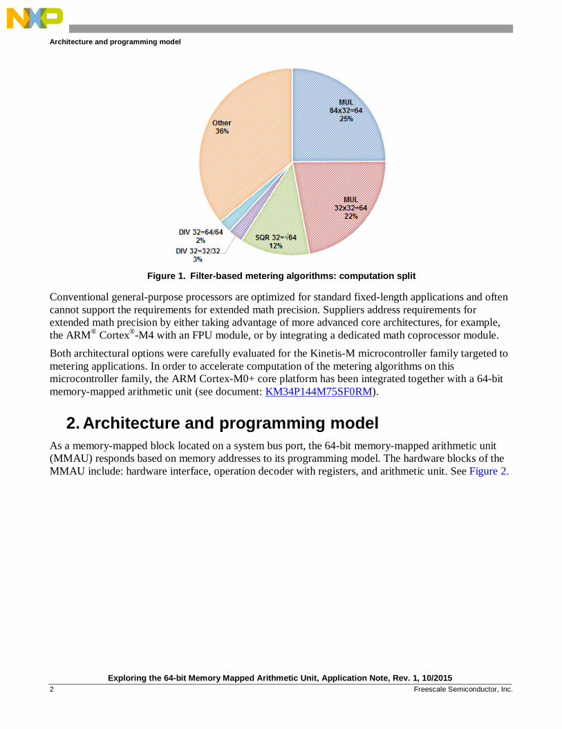
Figure 2. Internal structure of the memory-mapped arithmetic unit
While the performance of the standalone arithmetic unit can provide a several-fold increase for high-
dynamic range calculations versus the most common microcontroller cores, the computational
performance of the microcontroller would suffer without an efficient hardware interface. The hardware
interface comprises an operation decoder and couples a 64-bit arithmetic unit to the ARM Cortex-M0+
core. The 64-bit arithmetic unit is implemented as a hardwired logic circuit designed to calculate basic
operations such as multiply, multiply-accumulate in a single clock cycle, and more advanced operations
such divide and square-root in several clock cycles.
In order to maximize computation throughput, the hardware interface was based on the principle of
decorated memory-mapped computation operation launching. Table 1 shows an example of a decorated
memory-mapped address range.
X0 X1 X2 X3
A1
Operation Decoder
System Bus Address
64 - bit Arithmetic Unit
System Bus R/W Data
Operation trigger
Operation select
Address Range(s) Memory Map LUT
Hardware Interface
CSR CSR_IF_LCR
A0
Registers
Architecture and programming model
Exploring the 64-bit Memory Mapped Arithmetic Unit, Application Note, Rev. 1, 10/2015
4 Freescale Semiconductor, Inc.
Table 1. Part of the decorated memory map for arithmetic operations
Decorated operation code Register
identifier[4:2] Register
name
Operation
offset
address[11:0]
Operation
mnemonic
Operation
brief
description1
Address[11:2]
11 10 9 8 7 6 5 4 3 2
- 0 1 0 1 1 0 0 0 0 X0 0x2C0 (not used)
32=√64 QSRD
A10=√X32
- 0 1 0 1 1 0 0 0 1 X1 0x2C4 (not used)
- 0 1 0 1 1 0 0 1 0 X2 0x2C8 (LSW of radicand)
- 0 1 0 1 1 0 0 1 1 X3 0x2CC (MSW of radicand)
- 0 1 0 1 1 0 1 0 0 A0 0x2D0 (LSW of square root)
- 0 1 0 1 1 0 1 0 1 A1 0x2D4 (MSW of square root)
S 1 0 0 0 1 0 0 0 0 X0 0x440 (not used)
64=64*32 QMULD
A10=X21*X3
S 1 0 0 0 1 0 0 0 1 X1 0x444 (multiplicand)
S 1 0 0 0 1 0 0 1 0 X2 0x448 (LSW of multiplier)
S 1 0 0 0 1 0 0 1 1 X3 0x44C (MSW of multiplier)
S 1 0 0 0 1 0 1 0 0 A0 0x450 (LSW of product)
S 1 0 0 0 1 0 1 0 1 A1 0x454 (MSW of product)
S 1 1 1 1 0 0 0 0 0 X0 0x780 (LSW of numerator)
64=64/64 SDIVDD
A10=X10/X32
S 1 1 1 1 0 0 0 0 1 X1 0x784 (MSW of numerator)
S 1 1 1 1 0 0 0 1 0 X2 0x788 (LSW of denominator)
S 1 1 1 1 0 0 0 1 1 X3 0x78C (MSW of denominator)
S 1 1 1 1 0 0 1 0 0 A0 0x790 (LSW of quotient)
S 1 1 1 1 0 0 1 0 1 A1 0x794 (MSW of quotient)
In Table 1, each address within the decorated memory-mapped address range comprises a decorated
operation code and register identifier pointing to a register to be accessed. The decorated operation code
also differentiates whether the operation returns a saturated or non-saturated result. Advantageously, by
implementing decorated operation launching within the hardware interface, a single memory access is
required to load an operand to the input operand register and trigger the 64-bit arithmetic unit to perform
the required arithmetic operation.
A 64=64/64 signed divide operation (SDIVDD) is given as an example to be performed by the MMAU.
It comprises the following write and read memory accesses:
Example 1. 64=64/64 divide operation 1. ADDR(0x780) NUM_L // write least-significant 32 bits of numerator to X0 2. ADDR(0x784) NUM_H // write most-significant 32 bits of numerator to X1 3. ADDR(0x788) DEN_L // write least-significant 32 bits of denominator to X2 4. ADDR(0x78C) DEN_H // write most-significant 32 bits of denominator to X3,
// select & trigger 64=64/64 operation 5. QUOT_L ADDR(0x790) // read least-significant 32 bits of result from A0 6. QUOT_H ADDR(0x794) // read most-significant 32 bits of result from A1
1 It should be noted that a 2-digit numeric identifier suffix denotes 64-bit registers, for example, A10 refers to the concatenated
{A1, A0} register combination, etc. Furthermore, since all the registers are 32-bit (4 byte) values, the low-order two byte address bits [1:0] are always 0 and thus have not been included within the table.
Architecture and programming model
Exploring the 64-bit Memory Mapped Arithmetic Unit, Application Note, Rev. 1, 10/2015
Freescale Semiconductor, Inc. 5
2.1. Arithmetic operations
The hardware interface allows development of simple, short, and very efficient software wrappers to
load operands to the 64-bit arithmetic unit and retrieve computed results.
Example 2 shows the software wrapper for a 64=64/64 divide operation written in GCC inline
assembler.
Example 2. Software wrapper for d_sdiv_dd operation /***************************************************************************//*! * @brief Divide two 64-bit integer values returning a 64-bit integer * quotient. * @details The @ref d_sdiv_dd function divides two 64-bit integer values * returning a 64-bit integer quotient. * @param dnum @ref int64 integer value. * @param dden @ref int64 integer value. * @return @ref int64 integer value. * @note Quotient is stored in A10 register of the MMAU for next computation. ******************************************************************************/ #define d_sdiv_dd(dnum,dden) \ ({ \ register uint32 addr = (MMAU_SDIVDD|MMAU_X0); \ register int64 out = (dnum); \ register int64 inp = (dden); \ asm volatile \ ( \ "stm %0!,{%Q1,%R1}\n" \ "stm %0!,{%Q2,%R2}\n" \ "ldm %0!,{%Q1,%R1} ":"=l"(addr),"=l"(out):"l"(inp),"0"(addr),"1"(out) \ ); \ (int64)out; \ })
In total, 140 software wrappers for elementary and more advanced arithmetic functions were written to
give users full access to the MMAU integrated on the Kinetis-M microcontroller family. All software
wrapper functions sets for signed integer, unsigned integer and signed fractional data types are listed in
Table 2, Table 3, and Table 4.
Table 2. Software wrappers for signed integer data types
Return type SMUL SMULS SMAC SMACS SDIV SDIVS Load/Read
Exploring the 64-bit Memory Mapped Arithmetic Unit, Application Note, Rev. 1, 10/2015
8 Freescale Semiconductor, Inc.
MMAU can be configured to generate the DMA request when the 64-bit arithmetic unit is not busy so
that the user can use DMA to fetch the result and initiate execution of the new arithmetic operation.
2.5. Access mode
The MMAU can be accessed in both User Mode and Supervisor Mode. However, if the application
needs to prevent any CPU/DMA accesses from User Mode, assert a supervisor-only (SO) control bit in
the control and status register (CSR). When this bit is set, any access from User Mode is terminated with
a bus error.
NOTE
The supervisor-only (SO) control bit can only be changed by the CPU in
Supervisor Mode.
2.6. Context save and restore
When calling MMAU operations from the main software loop and also from interrupts or in nested
interrupts, your software is responsible for saving and restoring MMAU registers. This is necessary
because divide and square root operations are executing in more core clock cycles and therefore their
interruption could lead to result mismatch. This problem can be solved with functions for saving and
restoring MMAU registers and calling them at the entry and exit of the interrupt routine. Example 4
shows the implementation of the MMAU_StoreState function.
Example 4. MMAU_StoreState function #define store_state(p) \ { \ register uint32 _src = (uint32)(MMAU__REGRW|MMAU__X0); \ register uint32 _dst = (uint32)p; \ __asm volatile \ ( \ "ldm %0 ,{%0,r2,r3,r4,r5,r6,r7}\n" \ "stm %1!,{%0,r2,r3,r4,r5,r6,r7}\n" \ :"=l"(_src),"=l"(_dst):"0"(_src),"1"(_dst):"r2","r3","r4","r5","r6","r7" \ ); \ } /***************************************************************************//*! * @brief Store MMAU internal state to the software stack. * @details The @ref MMAU_StoreState function stores MMAU internal state * including operand, accumulator and control/status registers to the * software stack. * @note Call this function at entry point of any interrupt service routine * which uses @ref mmau_macros. At the exit of such interrupt service * routine you should call @ref MMAU_RestoreState function. * @see @ref MMAU_RestoreState ******************************************************************************/ #define MMAU_StoreState() tMMAU_STATE volatile __tmp; store_state(&__tmp)
The MMAU_StoreState function reads the state of the X0, X1, X2, X3, A0, A1, and CSR registers and
stores them on the stack. This function must be called at the beginning of each interrupt service routine
that calls MMAU operations.
Architecture and programming model
Exploring the 64-bit Memory Mapped Arithmetic Unit, Application Note, Rev. 1, 10/2015
Freescale Semiconductor, Inc. 9
Example 5 shows the implementation of the MMAU_RestoreState function.
Example 5. MMAU_RestoreState function #define restore_state(p) \ { \ register uint32 _src = (uint32)p; \ register uint32 _dst = (uint32)(MMAU__REGRW|MMAU__X0); \ __asm volatile \ ( \ "ldm %0 ,{%0,r2,r3,r4,r5,r6,r7}\n" \ "stm %1!,{%0,r2,r3,r4,r5,r6,r7}\n" \ :"=l"(_src),"=l"(_dst):"0"(_src),"1"(_dst):"r2","r3","r4","r5","r6","r7" \ ); \ } /***************************************************************************//*! * @brief Restore MMAU internal state from the software stack. * @details The @ref MMAU_RestoreState function restores MMAU internal state * including operand, accumulator and control/status registers from the * software stack. * @note Call this function at exit of any interrupt service routine * which uses @ref mmau_macros. At entry point of such interrupt * service routine you should call @ref MMAU_StoreState function. * @see @ref MMAU_StoreState ******************************************************************************/ #define MMAU_RestoreState() restore_state(&__tmp)
The MMAU_RestoreState function restores the state of the X0, X1, X2, X3, A0, A1, and CSR registers
from the stack. This function is complementary to the MMAU_StoreState function and it must be called
at the end of each interrupt service routine calling MMAU operations.
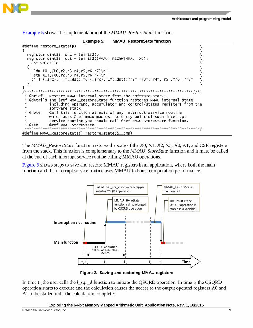
Figure 3 shows steps to save and restore MMAU registers in an application, where both the main
function and the interrupt service routine uses MMAU to boost computation performance.
Figure 3. Saving and restoring MMAU registers
In time t1, the user calls the l_sqr_d function to initiate the QSQRD operation. In time t2 the QSQRD
operation starts to execute and the calculation causes the access to the output operand registers A0 and
A1 to be stalled until the calculation completes.
Time t1 t
3 t
4 t
5 t
6
QSQRD operation takes max. 33 clock
cycles
t2
Call of the l_sqr_d software wrapper initiates QSQRD operation
MMAU_StoreState function call; prolonged by QSQRD operation
MMAU_RestoreState function call
The result of the QSQRD operation is stored in a variable
Main function
Interrupt service routine
Function examples and performance
Exploring the 64-bit Memory Mapped Arithmetic Unit, Application Note, Rev. 1, 10/2015
10 Freescale Semiconductor, Inc.
In time t3, interrupt occurs and therefore the software transitions to an interrupt service routine. The first
function that executes at interrupt entry is the MMAU_StoreState function. This function completes in
time t4 only after output operand registers A0 and A1 are updated wih the result of the QSQRD
operation and all MMAU registers stored on the stack. In time t5 the user restores MMAU registers from
the stack by calling the MMAU_RestoreState function.
Finally, in time t6 the interrupt service routine finishes and the software execution transitions back to the
l_sqr_d function, which reads the square root value from A0 and A1 output operand registers and stores
it in a variable.
The next section demonstrates the capabilities of the MMAU in computing signal processing algorithms.
Several algorithms, widely used in signal processing applications, have been implemented using MMAU
operations and their performance have been analyzed.
3. Function examples and performance
This section shows use of the MMAU in Power series, IIR filter, Goertzel algorithm, and FFT
computing. The algorithms were implemented in C-language, and their accuracy and performance
verified on the TWR-KM34Z75M Tower System Module.
NOTE
The IAR Embedded Workbench® for ARM
® (version 7.40.1) tool was
used to obtain performance data for all functions. The code was compiled
with full optimization for execution speed and MKM34Z256VLQ7 target.
The MKM34Z256VLQ7 device was clocked at 2 MHz using the Internal
Reference Clock. The execution times were measured in number of core
clock cycles using SysTick timer. The flash and RAM requirements are
represented in bytes.
3.1. Power series
A power series represents an infinite polynomial on variable and can be used to define a wide variety of
functions. This section shows the implementation of the sin(πx) function using the power series derived
for x=0.
Example 6 shows source code for the sin(πx) function implemented using fractional arithmetic. The
input argument, a 32-bit two's-complement value represents an angle in range –π and π. The output of
the function is also a 32-bit two's-complement value and represents the sine of the input angle in range
from -1 to 1.
Example 6. Sine function static const frac64 sin_coef[] = { FRAC64( 0.50000000000000), FRAC64(-0.82246703342411), FRAC64( 0.40587121264168), FRAC64(-0.09537591206104), FRAC64( 0.01307392390883), FRAC64(-0.00117304051773), FRAC64( 0.00006930000000) /* 0.00007421439652 */ };
Function examples and performance
Exploring the 64-bit Memory Mapped Arithmetic Unit, Application Note, Rev. 1, 10/2015
Freescale Semiconductor, Inc. 11
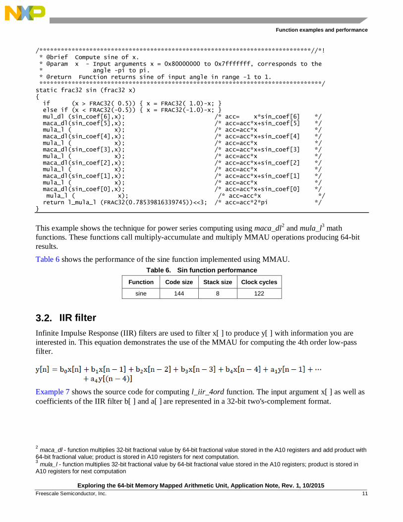
/****************************************************************************//*! * @brief Compute sine of x. * @param x - Input arguments x = 0x80000000 to 0x7fffffff, corresponds to the * angle -pi to pi. * @return Function returns sine of input angle in range -1 to 1. *******************************************************************************/ static frac32 sin (frac32 x) { if (x > FRAC32( 0.5)) { x = FRAC32( 1.0)-x; } else if (x < FRAC32(-0.5)) { x = FRAC32(-1.0)-x; } mul_dl (sin_coef[6],x); /* acc= x*sin_coef[6] */ maca_dl(sin_coef[5],x); /* acc=acc*x+sin_coef[5] */ mula_l ( x); /* acc=acc*x */ maca_dl(sin_coef[4],x); /* acc=acc*x+sin_coef[4] */ mula_l ( x); /* acc=acc*x */ maca_dl(sin_coef[3],x); /* acc=acc*x+sin_coef[3] */ mula_l ( x); /* acc=acc*x */ maca_dl(sin_coef[2],x); /* acc=acc*x+sin_coef[2] */ mula_l ( x); /* acc=acc*x */ maca_dl(sin_coef[1],x); /* acc=acc*x+sin_coef[1] */ mula_l ( x); /* acc=acc*x */ maca_dl(sin_coef[0],x); /* acc=acc*x+sin_coef[0] */ mula_l ( x); /* acc=acc*x */ return l_mula_l (FRAC32(0.78539816339745))<<3; /* acc=acc*2*pi */ }
This example shows the technique for power series computing using maca_dl2 and mula_l
3 math
functions. These functions call multiply-accumulate and multiply MMAU operations producing 64-bit
results.
Table 6 shows the performance of the sine function implemented using MMAU.
Table 6. Sin function performance
Function Code size Stack size Clock cycles
sine 144 8 122
3.2. IIR filter
Infinite Impulse Response (IIR) filters are used to filter x[ ] to produce y[ ] with information you are
interested in. This equation demonstrates the use of the MMAU for computing the 4th order low-pass
filter.
Example 7 shows the source code for computing l_iir_4ord function. The input argument x[ ] as well as
coefficients of the IIR filter b[ ] and a[ ] are represented in a 32-bit two's-complement format.
2 maca_dl - function multiplies 32-bit fractional value by 64-bit fractional value stored in the A10 registers and add product with
64-bit fractional value; product is stored in A10 registers for next computation. 3 mula_l - function multiplies 32-bit fractional value by 64-bit fractional value stored in the A10 registers; product is stored in
A10 registers for next computation
Function examples and performance
Exploring the 64-bit Memory Mapped Arithmetic Unit, Application Note, Rev. 1, 10/2015
12 Freescale Semiconductor, Inc.
The output of the function is also a 32-bit two's-complement value. All filter taps are calculated in a 64-
bit precision to maximize filter accuracy.
Example 7. 4th order infinite impulse response filter /****************************************************************************//*! * @brief Compute 4th order infinite impulse response filter (IIR) iteration: * y(n) = b(0)*x(n)+b(1)*x(n-1)+b(2)*x(n-2)+b(3)*x(n-3)+b(4)*x(n-4) * +a(1)*y(n-1)+a(2)*y(n-2)+a(3)*y(n-3)+a(4)*y(n-4) * Internal accumulations don't saturate. The IIR filter output is within * 32-bit fractional range from 0x80000000 to 0x7fffffff. * @param x - Input fractional value represented in 32-bit fractional format * "x(n)". * @param *pb - Pointer to filter constants "b" represented in 32-bit fractional * format "b(0) ... b(4)". * @param *pa - Pointer to filter constants "a" represented in 32-bit fractional * format "-a(1) ... -a(4)". * @param sc - Filter constants scaling. * @param *px - Pointer to previous input values represented in 32-bit fractional * format "x(n-1) ... x(n-4)". * @param *py - Pointer to previous output values represented in 32-bit fractional * format "y(n-1) ... y(n-4)". * @return Function returns 32-bit value in fractional format. *******************************************************************************/ static frac32 l_iir_4ord (frac32 x, const frac32 *pb, const frac32 *pa, int16 sc, frac32 *px, frac32 *py) { register frac32 y; /* actual filter output value calculation with using MMAU instructions */ mul_ll(*(pb ), x); /* acc= b[0]*x[0] */ mac_ll(*(pb+1),*(px )); /* acc=acc+b[1]*x[1] */ mac_ll(*(pb+2),*(px+1)); /* acc=acc+b[2]*x[2] */ mac_ll(*(pb+3),*(px+2)); /* acc=acc+b[3]*x[3] */ mac_ll(*(pb+4),*(px+3)); /* acc=acc+b[4]*x[4] */ mac_ll(*(py ),*(pa )); /* acc=acc+a[1]*y[1] */ mac_ll(*(py+1),*(pa+1)); /* acc=acc+a[2]*y[2] */ mac_ll(*(py+2),*(pa+2)); /* acc=acc+a[3]*y[3] */ y = l_mac_ll(*(py+3),*(pa+3))<<sc; /* y =(acc+a[4]*y[4])<<sc */ /* shifting previous input values */ *(px+3)=*(px+2); *(px+2)=*(px+1); *(px+1)=*(px); *(px)= x; /* shifting previous output values */ *(py+3)=*(py+2); *(py+2)=*(py+1); *(py+1)=*(py); *(py)= y; return y; }
The MMAU can compute such filter function with 64-bit precision quickly taking 18.6 core clock cycles
per TAP. This excellent performance is achieved as a result of mul_ll 4 and mac_ll
5 math functions.
These functions call multiply and multiply-accumulate MMAU operations producing 64-bit results.
4 mul_ll - function multiplies two 32-bit fractional values; product is stored in A10 registers of the MMAU for next computation.
5 mac_ll - function multiplies two 32-bit fractional values and add product with value stored in the A10 register of the MMAU;
product is stored in A10 registers of the MMAU for next computation
Function examples and performance
Exploring the 64-bit Memory Mapped Arithmetic Unit, Application Note, Rev. 1, 10/2015
Freescale Semiconductor, Inc. 13
Table 7 shows performance of the l_iir_4ord function implemented using MMAU.
Table 7. l_iir_4ord function performance.
Function Code size Stack size Clock cycles
l_iir_4ord 128 28 167
3.3. Goertzel algorithm
The Goertzel algorithm is very useful when detecting a small amount of frequencies (magnitudes and
phases) of the digital signal [1]. It computes real and imaginary frequency components as a regular
Discrete Fourier Transform (DFT) or FFT.
Example 8 shows the source code of the function for computing Goertzel algorithm. The input digital
signal x[ ] of length num is processed by the function to compute the magnitude of the specific harmonic
harm. The input digital signal samples are represented in a 32-bit two's-complement format ranging
from 0xff800000 to 0x007fffff. The function returns magnitude in a 32-bit two's-complement format in
range from 0 to 0x007fffff.
Example 8. Goertzel algorithm /****************************************************************************//*! * @brief Compute cosine of x. * @param x - Input argument x = 0x80000000 to 0x7fffffff, corresponds to the * angle -pi to pi. * @return Function returns cosine of input angle in range -1 to 1. *******************************************************************************/ static frac32 cos (frac32 x) { return sin(x+FRAC32(0.5)); /* sin(x+pi/2) */ } /****************************************************************************//*! * @brief Compute magnitude of the harmonic of the signal waveform x. * @param num - Number of samples. * harm- Harmonic of the signal waveform to be computed. * x - Pointer to input signal samples. * @return Function returns magnitude of the input signal waveform at given * harmonic. *******************************************************************************/ static frac24 goertzel (register int num, register int harm, register const frac24 x[]) { register frac32 tmp2 = d_udiv_dl(d_umul_dl(FRAC32(2.0),harm),num), tmp1 = cos(tmp2); register frac64 a2 = 0ll, a1 = x[0], tmp3; register int i = 0; while (++i < num) { tmp3 = a1; a1 = d_mul_dl(a1+a1,tmp1)+x[i]-a2; a2 = tmp3; } tmp2 = d_sdiv_dl(d_mul_dl(a1,sin(tmp2)),num>>1); tmp1 = d_sdiv_dl(d_mul_dl(a1,tmp1)-a2 ,num>>1); mul_ll(tmp1,tmp1); mac_ll(tmp2,tmp2); return l_sqra(); }
Function examples and performance
Exploring the 64-bit Memory Mapped Arithmetic Unit, Application Note, Rev. 1, 10/2015
14 Freescale Semiconductor, Inc.
In addition to elementary multiply and multiply-accumulate operations of the MMAU, the Goertzel
algorithm also uses more advanced divide and square root operations. These operations are called by
d_udiv_dl 6 , d_sdiv_dl
7, and l_sqra
8 function wrappers and they execute with a maximum of 33 clock
cycles depending on the values of the input arguments. The internal computations are performed with
64-bit precision but the result is truncated to a 32-bit value.
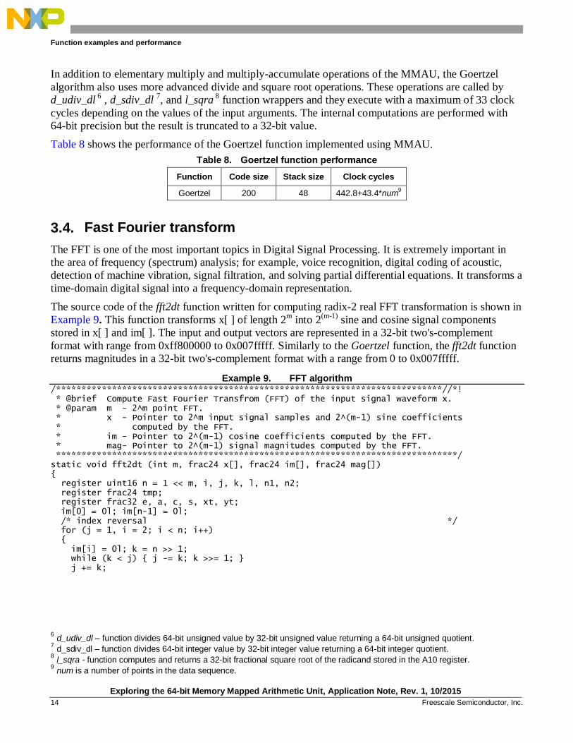
Table 8 shows the performance of the Goertzel function implemented using MMAU.
Table 8. Goertzel function performance
Function Code size Stack size Clock cycles
Goertzel 200 48 442.8+43.4*num9
3.4. Fast Fourier transform
The FFT is one of the most important topics in Digital Signal Processing. It is extremely important in
the area of frequency (spectrum) analysis; for example, voice recognition, digital coding of acoustic,
detection of machine vibration, signal filtration, and solving partial differential equations. It transforms a
time-domain digital signal into a frequency-domain representation.
The source code of the fft2dt function written for computing radix-2 real FFT transformation is shown in
Example 9. This function transforms x[ ] of length 2m into 2
(m-1) sine and cosine signal components
stored in x[ ] and im[ ]. The input and output vectors are represented in a 32-bit two's-complement
format with range from 0xff800000 to 0x007fffff. Similarly to the Goertzel function, the fft2dt function
returns magnitudes in a 32-bit two's-complement format with a range from 0 to 0x007fffff.
Example 9. FFT algorithm /****************************************************************************//*! * @brief Compute Fast Fourier Transfrom (FFT) of the input signal waveform x. * @param m - 2^m point FFT. * x - Pointer to 2^m input signal samples and 2^(m-1) sine coefficients * computed by the FFT. * im - Pointer to 2^(m-1) cosine coefficients computed by the FFT. * mag- Pointer to 2^(m-1) signal magnitudes computed by the FFT. *******************************************************************************/ static void fft2dt (int m, frac24 x[], frac24 im[], frac24 mag[]) { register uint16 n = 1 << m, i, j, k, l, n1, n2; register frac24 tmp; register frac32 e, a, c, s, xt, yt; im[0] = 0l; im[n-1] = 0l; /* index reversal */ for (j = 1, i = 2; i < n; i++) { im[i] = 0l; k = n >> 1; while (k < j) { j -= k; k >>= 1; } j += k;
6 d_udiv_dl – function divides 64-bit unsigned value by 32-bit unsigned value returning a 64-bit unsigned quotient.
7 d_sdiv_dl – function divides 64-bit integer value by 32-bit integer value returning a 64-bit integer quotient.
8 l_sqra - function computes and returns a 32-bit fractional square root of the radicand stored in the A10 register.
9 num is a number of points in the data sequence.
Function examples and performance
Exploring the 64-bit Memory Mapped Arithmetic Unit, Application Note, Rev. 1, 10/2015
Freescale Semiconductor, Inc. 15
if (i < j) { tmp = x[j-1]; x[j-1] = x[i-1]; x[i-1] = tmp; } } /* main fft loops */ for (n1 = 1, k = 1; k <= m; k++) { n2 = n1; n1 = n2 << 1; e = l_udiv_ll (0xffffffff,n1); for (a = 0, j = 0; j < n2; j++) { c = cos (a); s = sin (a); a = d_umul_ll (e,j+1); for (i = j; i < n; i += n1) { l = i+n2; mul_ll (s, im[l]); xt = l_mac_ll (c, x[l]); mul_ll (s, -x[l]); yt = l_mac_ll (c,im[l]); x[l] = x[i]-xt; x[i] = x[i]+xt; im[l] = im[i]-yt; im[i] = im[i]+yt; } } } /* compute amplitudes */ for (i=0; i < n; i++) { mul_ll (x[i],x[i]); mac_ll (im[i],im[i]); mag[i] = l_sqra() >> (m-1); } }
The MMAU accelerates FFT computing in more areas. The inner loops including sine and cosine
computing, are greatly accelerated by the multiply and multiply-accumulate MMAU operations. In
addition, magnitude computing is boosted by square root computing.
The main loop performs internal computations with 64-bit precision to achieve better accuracy of
conversion time-domain signals into frequency-domain representation.
Table 9 shows the performance of the fft2dt function implemented using MMAU.
Table 9. fft2dt function performance
Function Code size Stack size Clock cycles
fft2dt 722 72 -2726.3+782.7*2m10
3.5. Performance summary
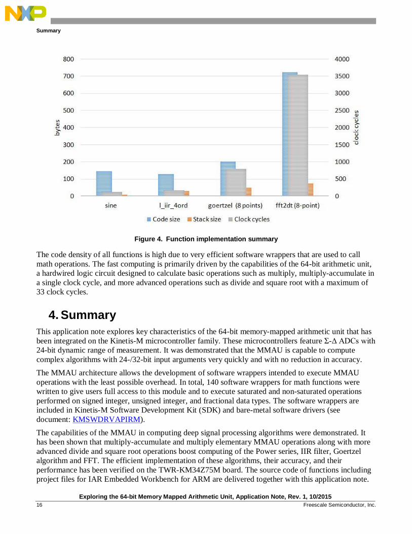
Figure 4 shows the performance of functions implemented with 64-bit precision and boosted by
MMAU.
10
2m is a number of point DIT FFT.
Summary
Exploring the 64-bit Memory Mapped Arithmetic Unit, Application Note, Rev. 1, 10/2015
16 Freescale Semiconductor, Inc.
Figure 4. Function implementation summary
The code density of all functions is high due to very efficient software wrappers that are used to call
math operations. The fast computing is primarily driven by the capabilities of the 64-bit arithmetic unit,
a hardwired logic circuit designed to calculate basic operations such as multiply, multiply-accumulate in
a single clock cycle, and more advanced operations such as divide and square root with a maximum of
33 clock cycles.
4. Summary
This application note explores key characteristics of the 64-bit memory-mapped arithmetic unit that has
been integrated on the Kinetis-M microcontroller family. These microcontrollers feature Σ-Δ ADCs with
24-bit dynamic range of measurement. It was demonstrated that the MMAU is capable to compute
complex algorithms with 24-/32-bit input arguments very quickly and with no reduction in accuracy.
The MMAU architecture allows the development of software wrappers intended to execute MMAU
operations with the least possible overhead. In total, 140 software wrappers for math functions were
written to give users full access to this module and to execute saturated and non-saturated operations
performed on signed integer, unsigned integer, and fractional data types. The software wrappers are
included in Kinetis-M Software Development Kit (SDK) and bare-metal software drivers (see
document: KMSWDRVAPIRM).
The capabilities of the MMAU in computing deep signal processing algorithms were demonstrated. It
has been shown that multiply-accumulate and multiply elementary MMAU operations along with more
advanced divide and square root operations boost computing of the Power series, IIR filter, Goertzel
algorithm and FFT. The efficient implementation of these algorithms, their accuracy, and their
performance has been verified on the TWR-KM34Z75M board. The source code of functions including
project files for IAR Embedded Workbench for ARM are delivered together with this application note.