Journal of Digital Forensics, Journal of Digital Forensics, Security and Law Security and Law Volume 10 Number 4 Article 7 2015 Exploring The Use Of PLC Debugging Tools For Digital Forensic Exploring The Use Of PLC Debugging Tools For Digital Forensic Investigations On SCADA Systems Investigations On SCADA Systems Tina Wu University of Oxford Jason R.C. Nurse University of Oxford Follow this and additional works at: https://commons.erau.edu/jdfsl Part of the Computer Engineering Commons, Computer Law Commons, Electrical and Computer Engineering Commons, Forensic Science and Technology Commons, and the Information Security Commons Recommended Citation Recommended Citation Wu, Tina and Nurse, Jason R.C. (2015) "Exploring The Use Of PLC Debugging Tools For Digital Forensic Investigations On SCADA Systems," Journal of Digital Forensics, Security and Law: Vol. 10 : No. 4 , Article 7. DOI: https://doi.org/10.15394/jdfsl.2015.1213 Available at: https://commons.erau.edu/jdfsl/vol10/iss4/7 This Article is brought to you for free and open access by the Journals at Scholarly Commons. It has been accepted for inclusion in Journal of Digital Forensics, Security and Law by an authorized administrator of Scholarly Commons. For more information, please contact [email protected]. (c)ADFSL
Transcript
Journal of Digital Forensics, Journal of Digital Forensics,
Security and Law Security and Law
Volume 10 Number 4 Article 7
2015
Exploring The Use Of PLC Debugging Tools For Digital Forensic Exploring The Use Of PLC Debugging Tools For Digital Forensic
Investigations On SCADA Systems Investigations On SCADA Systems
Tina Wu University of Oxford
Jason R.C. Nurse University of Oxford
Follow this and additional works at: https://commons.erau.edu/jdfsl
Part of the Computer Engineering Commons, Computer Law Commons, Electrical and Computer
Engineering Commons, Forensic Science and Technology Commons, and the Information Security
Commons
Recommended Citation Recommended Citation Wu, Tina and Nurse, Jason R.C. (2015) "Exploring The Use Of PLC Debugging Tools For Digital Forensic Investigations On SCADA Systems," Journal of Digital Forensics, Security and Law: Vol. 10 : No. 4 , Article 7. DOI: https://doi.org/10.15394/jdfsl.2015.1213 Available at: https://commons.erau.edu/jdfsl/vol10/iss4/7
This Article is brought to you for free and open access by the Journals at Scholarly Commons. It has been accepted for inclusion in Journal of Digital Forensics, Security and Law by an authorized administrator of Scholarly Commons. For more information, please contact [email protected].
Exploring the Use of PLC Debugging Tools for Digital Forensic ... JDFSL V10N4
EXPLORING THE USE OF PLCDEBUGGING TOOLS FOR DIGITAL
FORENSIC INVESTIGATIONS ON SCADASYSTEMS
Tina Wu and Jason R.C. NurseCyber Security Centre
Department of Computer ScienceUniversity of Oxford
Oxford, United Kingdom{tina.wu,jason.nurse}@cs.ox.ac.uk
ABSTRACT
The Stuxnet malware attack has provided strong evidence for the development of a forensiccapability to aid in thorough post-incident investigations. Current live forensic tools are typ-ically used to acquire and examine memory from computers running either Windows or Unix.This makes them incompatible with embedded devices found on SCADA systems that havetheir own bespoke operating system. Currently, only a limited number of forensics tools havebeen developed for SCADA systems, with no development of tools to acquire the programcode from PLCs. In this paper, we explore this problem with two main hypotheses in mind.Our first hypothesis was that the program code is an important forensic artefact that can beused to determine an attacker’s intentions. Our second hypothesis was that PLC debuggingtools can be used for forensics to facilitate the acquisition and analysis of the program codefrom PLCs. With direct access to the memory addresses of the PLC, PLC debugging toolshave promising functionalities as a forensic tool, such as the ”Snapshot” function that allowsusers to directly take values from the memory addresses of the PLC, without vendor specificsoftware. As a case example we will focus on PLC Logger as a forensic tool to acquire andanalyse the program code on a PLC. Using these two hypotheses we developed two exper-iments. The results from Experiment 1 provided evidence to indicate that it is possible toacquire the program code using PLC Logger and to identify the attacker’s intention, there-fore our hypothesis was accepted. In Experiment 2, we used an existing Computer ForensicsTool Testing (CFTT) framework by NIST to test PLC Logger’s suitability as a forensic toolto analyse and acquire the program code. Based on the experiment’s results, this hypothesiswas rejected as PLC Logger had failed half of the tests. This suggests that PLC Logger in itscurrent state has limited suitability as a forensic tool, unless the shortcomings are addressed.
Keywords: PLC debugging, program code, SCADA, digital forensics, NIST, PLCs, attack-ers
JDFSL V10N4 Exploring the Use of PLC Debugging Tools for Digital Forensic ...
1. INTRODUCTIONSupervisory Control and Data Acquisition(SCADA) systems are used to gather, mon-itor and analyse real-time data in an au-tomated manner. They provide the un-derlying architecture for many critical in-frastructures including power plants, wa-ter, oil and gas distributions systems. Ini-tially SCADA systems were isolated allow-ing a degree of protection. The adoption ofethernet TCP/IP and wireless technologies(such as IEEE 802.x) in these systems, how-ever has significantly reduced this isolation.The connection to the enterprise networkleaves SCADA systems, that were previouslyair-gapped, vulnerable to an ever-increasingrange of external attacks (Zhu, Joseph, &Sastry, 2011).
In recent years there have been several,well-documented attacks including a sophis-ticated malware designed specifically to at-tack SCADA systems, known as the Stuxnetvirus. This virus exploits multiple vul-nerabilities in Windows to target the soft-ware used to program Programmable LogicControllers (PLCs) central to the opera-tion of SCADA systems. One of the keyattack mechanisms of Stuxnet was the re-programming of the program code on thePLCs (Falliere, Murchu, & Chien, 2011).To respond to attacks on SCADA systems,forensics play a critical role. A forensic in-vestigation can be used to identify who car-ried out the attack, to define their inten-tions and also to understand their method-ology. Not only is it important to use theinformation discovered during the investiga-tion in order to attribute the attack, it isalso essential that it is used to improve se-curity measures on the SCADA system andto share the threat intelligence informationwith other SCADA sites. In the past, digitalforensics focused on normal IT setups withconsumer electronics and enterprise systems
involving computers with hard drives, themajority using the Windows Operating Sys-tem (OS). The attack surface of a control-system environment however, is very differ-ent to a typical IT environment. Some of themain differences include the fact that thereare many embedded devices using bespokeprotocols and OSs, and many systems stillusing outdated and unpatched OSs (Zhu etal., 2011).
Most related research has focused on thedevelopment of live forensic frameworks us-ing agents to collect forensic artefacts fromSCADA systems such as (Ahmed, Ober-meier, Naedele, & Richard, 2012) (Taveras,2013) (Kilpatrick, Gonzalez, Chandia, Papa,& Shenoi, 2006). Many of these approacheshave focused on acquiring evidence fromcomputer systems. However, the focusshould arguably shift to acquiring evidencefrom PLCs as they are a crucial componentsin SCADA systems (as seen in the Stuxnetcase where a critical PLC component wasattacked). Moreover the majority of currentresearch in SCADA forensics is theoreticalwith many authors such as (Taveras, 2013)not having tested the practical use of theirproposed approach.
The novelty of our research is exploringthe utility of PLC debugging tools in sup-porting forensic investigations. Specificallythis will be used to acquire the memory ad-dresses from a Siemens S7 PLC and explorethe suitability of PLC Logger for forensic in-vestigations on SCADA systems. PLC de-bugging tools have promising functionalitiessuch as communication with the PLC with-out using vendor specific software and directaccess to the memory of the PLC. Howeverit is unclear whether such tools are useful forforensic investigations.
Our research question is; can PLC debug-ging tools be used to support digital foren-sic investigations on SCADA systems? Fromthis research question we developed two hy-
Exploring the Use of PLC Debugging Tools for Digital Forensic ... JDFSL V10N4
potheses, these are:• Program code is an important forensic
artefact that can be used to determinean attacker’s intentions.• PLC debugging tools can be used as a
forensic tool to acquire and analyse theprogram code from a PLC.
The paper is structured as follows: In Sec-tion 2, we discuss related work on SCADAforensics, live forensics data and the instal-lation of agents on a SCADA network andrelated data acquisition methods. Section 3discusses the forensic artefacts that can beacquired from PLCs but also artefacts specif-ically from Siemens S7 PLCs. In Section4, we present an overview of NIST’s Com-puter Forensics Tool Testing (CFTT) frame-work and the purpose of its use. In Sec-tion 5, we introduce our experimental setup,the PLC Logger tool and the program code.Next, Section 6 presents the experiment re-sults and a critical reflection on the use ofthe PLC program code to investigate the at-tacker’s intentions, and to test PLC Loggerfor its suitability as a forensic tool for PLCsusing NIST’s CFTT framework. Finally Sec-tion 7 concludes this paper and presents fu-ture work.
2. RELATED
RESEARCHThere is a large amount of existing researchin the area of forensics on SCADA systems.In particular, several authors have pro-posed the installation of agents on SCADAnetworks to conduct live forensic acquisi-tion (Ahmed et al., 2012),(Kilpatrick et al.,2006). Live data acquisition is the extrac-tion of data when the device is still running;in digital forensics this is normally used torecover RAM in the memory of a computer(Jones, 2007). There are two methods of livedata acquisitions. The first method requires
an agent to be pre-installed on the host com-puter. Data can then be acquired throughthe network to extract artefacts in a largenetwork such as an enterprise environment.These agents include open source tools suchas Googles GRR Rapid Response1 and pro-prietor software such as EnCase Enterprise2.The second method extracts data using anagent customised depending on the forensicartefacts required. These include tools suchas Mandiant Redline3 often used in IncidentResponse (IR) to find signs of malicious ac-tivity in the device’s memory.
(Kilpatrick et al., 2006) propose imple-menting agents across the control network,the agents then send network packets backto a data warehouse on an isolated net-work to prevent external access. This tech-nique relies on trust that the agents havenot been compromised, or that the networkpackets sent back to the data warehouse havenot been modified during transit. (Taveras,2013) proposes the use of a finite state au-tomaton as an agent that would monitorSCADA events in real-time. These eventsare then compared against a set of rules todetermine whether any changes have beenmade to the state. If changes have beenidentified the agent then switches to foren-sic mode to log the information for use in aforensic investigation. However, further re-search would be required to test this on atestbed simulation to assess its effectivenesson a real SCADA system.
(Radvanovsky & Brodsky, 2013) haveidentified that obtaining the hexadecimaldump from the memory of the PLC can beuseful in a forensic investigation. The filesystem can be checked for known malwaresignatures and compared against expectedfile signatures to determine changes to the
JDFSL V10N4 Exploring the Use of PLC Debugging Tools for Digital Forensic ...
file system. The authors have not suggesteda practical solution to extract the hexadeci-mal dump from the PLC, currently there areno methods to achieve this.
(Van der Knijff, 2014) examined an attackscenario and discussed the forensic methodsand tools that could possibly be used fora forensic investigation on the SCADA sys-tem. The author stated potential artefactsstored in the RAM of the PLC would belost if rebooted. They have suggested in or-der to preserve the potential evidence in theRAM it would need to be switched to pro-gramming mode. This is an hypothesis theyhave concluded and have not carried out apractical element to prove their hypothesisis correct. In order to switch the PLC intoprogramming mode specific software wouldhave to be obtained from the vendor. In cir-cumstances where this is unavailable, the au-thor has suggested the use of debugging toolsconnecting through the Joint Action TestGroup (JTAG) port or physical removal ofthe chips. However it is rare that a SCADAsystem will have a back-up system that al-lows a PLC to be taken offline. This couldbe an issue with the SCADA system ownerswho would be unlikely to allow this.
A key limitation with the majority ofexisting work such as (Ahmed et al.,2012)(Patzlaff, 2013) is they have not con-ducted a practical evaluation of their forensicframework. In order to establish if their im-plementation is capable of extracting foren-sic artefacts from PLCs.
3. FORENSIC
ARTEFACTS FROM
PLCS
3.1 Existing Research
Here we explore the forensics artefacts thatcan be retrieved from PLCs. In traditional
computer forensics, forensic artefacts arenormally defined as artefacts that have beenexposed by a forensic investigator to revealthe truth about an event that has been lefton the system (Clarke, Tryfonas, & Dodge,2012). On a PLC there are two sources ofevidence that can be obtained i.e; the de-vice and network traffic. The focus of ourresearch will be on forensic artefacts retriev-able from devices. Network traffic on its ownwould not be sufficient as it cannot providehardware level data.
(ENISA, 2013) has identified some typesof data that can be extracted from field de-vices such as date and time, current activeprocesses and logs. They have identified thatin order to be able to acquire data from fielddevices they need to work with control sys-tem engineers and vendors to support theinvestigation.
In terms of a PLC, the forensic process andtools to be used would be highly dependenton the make and model of the PLC. It wouldtherefore be useful to gather informationsuch as vendor of the PLC, firmware version,date and time on the PLC, IP Address, serialnumber of the PLC, model name, and thetype of Computer Processing Unit (CPU).
To the best of our knowledge, no re-search has currently identified whether thereis any useful evidence on PLCs that may beused to support a forensic investigation of aSCADA system. The attack using Stuxnetinvolved the reprogramming of the PLC pro-gram code and the installation of malware.Therefore we hypothesise that there are po-tential artefacts in the reprogrammed code,that can be used the to establish the at-tacker’s intentions (Falliere et al., 2011).There are other malicious attacks on PLCssuch as firmware counterfeiting and modi-fications (Basnight, 2013) and uploading ofmalware (McLaughlin, 2011). This paper fo-cuses on a modification attack on the PLCprogram code, as to our knowledge there has
Exploring the Use of PLC Debugging Tools for Digital Forensic ... JDFSL V10N4
been limited research in this area (consider-ing this occurred in the Stuxnet attack).
There is a feasible scenario where an at-tacker could maliciously alter the PLC pro-gram code to perform the initial attack.When this is complete the attacker could ac-cess the PLC again to revert to the originalprogram code in the PLC or to enter anyrandom program code they choose. In thissituation we would not be able to rely on theprogram code from the PLC without othersources of evidence from the SCADA sys-tem. For example captured network trafficand event logs.
Our approach is general, but for this spe-cific test case in the paper, we are using theSiemens S7-1200 PLC. This PLC was cho-sen for our experiments, as it is a commonbrand of PLC with wide support and de-velopers regularly creating libraries to sup-port communication with Siemens S7 PLCs.The next section explores the structure ofthe program code on Siemens S7 PLCs.
3.2 Siemens S7 PLCs
The Siemens S7 protocol is a proprietaryprotocol used to communicate with PLCsof the Siemens family. The main purposeof the protocol is to exchange data amongPLCs and access data from SCADA sys-tems for diagnostics purposes. The SiemensS7 TCP/IP protocol communicate usingport 102 and can be programmed using theTIA Portal Step 7 software. According toSiemens, a typical S7 PLC stores programcode and configuration data within the Ran-dom Access Memory (RAM). The struc-ture of RAM changes frequently as it is thevolatile area of the memory, (i.e when poweris removed the data stored is lost) (Vidas,2007).
Siemens structure their program code bystoring them in blocks, limited to 1024. Theprogram code uses memory addresses to ac-cess information in the memory location.
The following are blocks of code used tostructure the program code:• Organisation Block (OB): provides
structure to the program and allows theinterface between the OS and the userprogram; it is the entry point of a pro-gram;• Function Code (FC): performs a specific
operation on a set of input values. TheFC stores the results of this operationin the memory location;• Data Block (DB): contains program
specific data such as numbers and struc-tures;• Function Block (FB): use an instance
DB for its parameters and static data.FB has variable memory located in aDB; and• System Data Block (SDB): contains
information on how the PLC is con-figured. They are created depend-ing on the number and type of hard-ware modules that are connected to thePLC (Siemens, 2015).
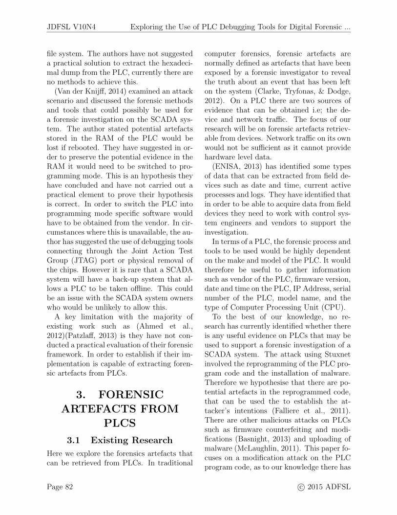
Forensic artefacts within the Siemens S7PLCs are the blocks of code (programblocks) such as OB and FBs. Other impor-tant artefacts are within the blocks of codescontaining memory addresses as shown inFigure 1. The blocks of code and memoryaddresses can be used to reconstruct the pro-gram code back to its raw format, in order toidentify modifications made by attacker todetermine their intentions. For example inthe scenario of a traffic control system, theattacker may change the program code in-tending to modify the traffic lights sequenceto cause accident or traffic chaos.
JDFSL V10N4 Exploring the Use of PLC Debugging Tools for Digital Forensic ...
Figure 1. Forensic artefacts of a program code on a Siemens S7 PLCs
4. NIST’S COMPUTER
FORENSICS TOOL
TESTING (CFTT)
FRAMEWORKThe CFTT field is a well researched areawith many frameworks developed by the Na-tional Institute of Standards and Technol-ogy (NIST) (NIST, 2007) to test forensictools. The CFTT framework has been fur-ther refined for specific areas of forensicsby (Rick Ayers, 2013),(Flandrin, Buchanan,Macfarlane, Ramsay, & Smales, 2014). Sincethe CFTT framework involves testing of var-ious computer forensic toolkits the sameprinciples are also applicable to other foren-sic tools, for example forensic tools for PLCs.The purpose of testing forensic tools is tomeasure validity of the results, to under-stand the tool’s capabilities and to allow de-velopers to improve the tool, including itsfunctionality and utility.
Currently there are a limited number offully developed forensic tools for SCADAand crucially no specific framework to testa SCADA forensic tools. The aim of our ex-periment is to test PLC debuggers, in this
case example PLC Logger for its suitabilityas a forensic acquisition and analysis tool forPLCs. It is not within our scope of this pa-per to develop a framework to test tools forSCADA systems. Instead we used existingresearch to test the suitability of PLC Log-ger. This enabled us to follow an alreadyestablished standard that is a recognised in-dustry framework.
5. EXPERIMENTAL
SETUPThe purpose of the experiments is to testPLC debugging tools, in this case examplewe test PLC Logger to explore its suitabilityas an acquisition and analysis tool to sup-port forensic investigations. The followingsection provides an explanation of PLC Log-ger and the program code showing the sce-nario of a traffic control system required forthe experiments. We constructed two exper-iments based on the two hypotheses, theseare:
1. Experiment 1: investigate if the pro-gram code once acquired can be usedto determine an attacker’s intentions.
2. Experiment 2: examined whether PLCLogger is suitable as a forensic acquisi-
Exploring the Use of PLC Debugging Tools for Digital Forensic ... JDFSL V10N4
tion and analysis tool using an existingNIST CFTT framework.
5.1 Tool: PLC Logger
Based on documentation retrieved aboutPLC Logger4, it is used to store and anal-yse data from various vendors; this includesthe Siemens S7, CoDeSys and Modbus TCPprotocol-based PLCs. The configuration filestores data about a PLC that is acquiredand can be saved as a PLCLogFile (.PLF).The protocol configuration can be stored as aPLCConfigurationFile (.PCF). Finally, anygathered data such as output values from thememory addresses, can then be visualised ina graph. PLC Logger is normally used torecord data on PLCs for diagnostic purposessuch as tracing faults in machinery and toimprove the efficiency of the system. PLCLogger was chosen because it is capable ofaccessing the memory areas of the PLC whilealso recording timestamped data. Moreoverit has the capability to record data from anumber of PLCs simultaneously. As a foren-sic tool for a SCADA system, this recoveringcapability would be an important feature, asit is anticipated that there are a number ofPLCs on the system.
5.2 The Program Code
For our experiment, program code was de-veloped based on an attack scenario involv-ing a traffic control system. We narroweddown our approach to an example of a sin-gle pedestrian crossing with Traffic Lights(TLs). Siemens TIA Portal Step 7 program-ming software was used to create the pro-gram code and upload onto the Siemens S7-1200 PLC. Table 1 shows a block of codefrom OB1 and contains the memory ad-dresses of the program code. The followingprovides a further explanation of the pro-gram code shown in the table.
4http://sourceforge.net/projects/plclogger/
In the first instance, when the programcode is uploaded onto the PLC it is in State0, this means that the TLs are currentlygreen (Q0.2) and the Pedestrian Lights(PLs) are red (Q0.3); see Figure 2. When thePL button (I0.6,I0.7) is pressed, the timercounts for two seconds and then goes to State1 turning the TLs amber (Q0.1) and the PLsremain red (Q0.3). In State 2 both TLs andPLs are red (Q0.0) and in State 3 the TLsare red (Q0.0) and the PLs green (Q0.4). InState 4 the TLs turn amber (Q0.1) and thePL turn red (Q0.3) before reverting back toState 0.
Figure 2. Program Code based on a Scenarioof a Traffic Lights and Pedestrian Crossing
Using PLC Logger and the program codethe following two experiments were con-ducted.
5.3 Experiment 1
Our first hypothesis is that by acquiring theprogram code, we will be able to gain valu-able artefacts that could allow us to deter-mine the attacker’s intentions. To test thishypothesis we conducted the experiment us-ing the following steps:
1. We uploaded the program code onto theSiemens S7-1200 PLC.
2. We took the memory addresses (shownin Table 1) from the program code andentered these into the PLC Logger con-figuration interface.
JDFSL V10N4 Exploring the Use of PLC Debugging Tools for Digital Forensic ...
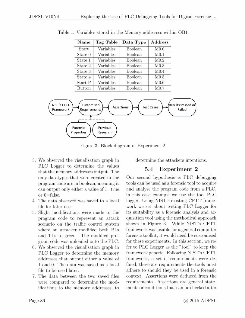
Table 1. Variables stored in the Memory addresses within OB1
Name Tag Table Data Type Address
Start Variables Boolean M0.0
State 0 Variables Boolean M0.1
State 1 Variables Boolean M0.2
State 2 Variables Boolean M0.3
State 3 Variables Boolean M0.4
State 4 Variables Boolean M0.5
Start P Variables Boolean M0.6
Button Variables Boolean M0.7
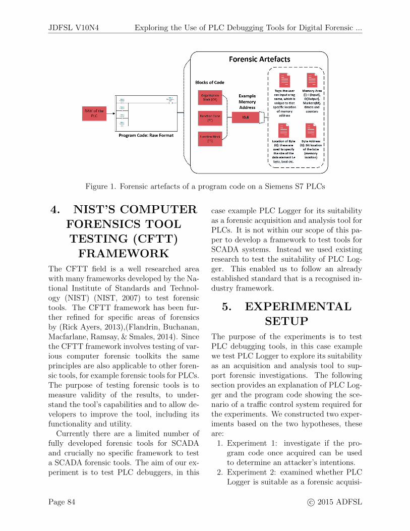
Figure 3. Block diagram of Experiment 2
3. We observed the visualisation graph inPLC Logger to determine the valuesthat the memory addresses output. Theonly datatypes that were created in theprogram code are in boolean, meaning itcan output only either a value of 1=trueor 0=false.
4. The data observed was saved to a localfile for later use.
5. Slight modifications were made to theprogram code to represent an attackscenario on the traffic control systemwhere an attacker modified both PLsand TLs to green. The modified pro-gram code was uploaded onto the PLC.
6. We observed the visualisation graph inPLC Logger to determine the memoryaddresses that output either a value of1 and 0. The data was saved as a localfile to be used later.
7. The data between the two saved fileswere compared to determine the mod-ifications to the memory addresses, to
determine the attackers intentions.
5.4 Experiment 2
Our second hypothesis is PLC debuggingtools can be used as a forensic tool to acquireand analyse the program code from a PLC,in this case example we use the tool PLClogger. Using NIST’s existing CFTT frame-work we set about testing PLC Logger forits suitability as a forensic analysis and ac-quisition tool using the methodical approachshown in Figure 3. While NIST’s CFTTframework was usable for a general computerforensic toolkit, it would need be customisedfor these experiments. In this section, we re-fer to PLC Logger as the ”tool” to keep theframework generic. Following NIST’s CFTTframework, a set of requirements were de-fined; these are requirements the tools mustadhere to should they be used in a forensiccontext. Assertions were deduced from therequirements. Assertions are general state-ments or conditions that can be checked after
Exploring the Use of PLC Debugging Tools for Digital Forensic ... JDFSL V10N4
a test is executed. The assertions are thentransformed into a set of test cases, these area combination of test parameters required toassess each assertion.
5.4.1 Requirements
The following are requirements that set abase criteria the tool should achieve, theseare gathered from a combination of previ-ous research by (Patzlaff, 2013) who havea detailed list of requirements that a foren-sic tool for a PLC should meet. Additionalrequirements were developed based on foren-sic properties that a acquisition and analysisforensic tool should provide (Carrier, 2003).The requirements are defined as follows.
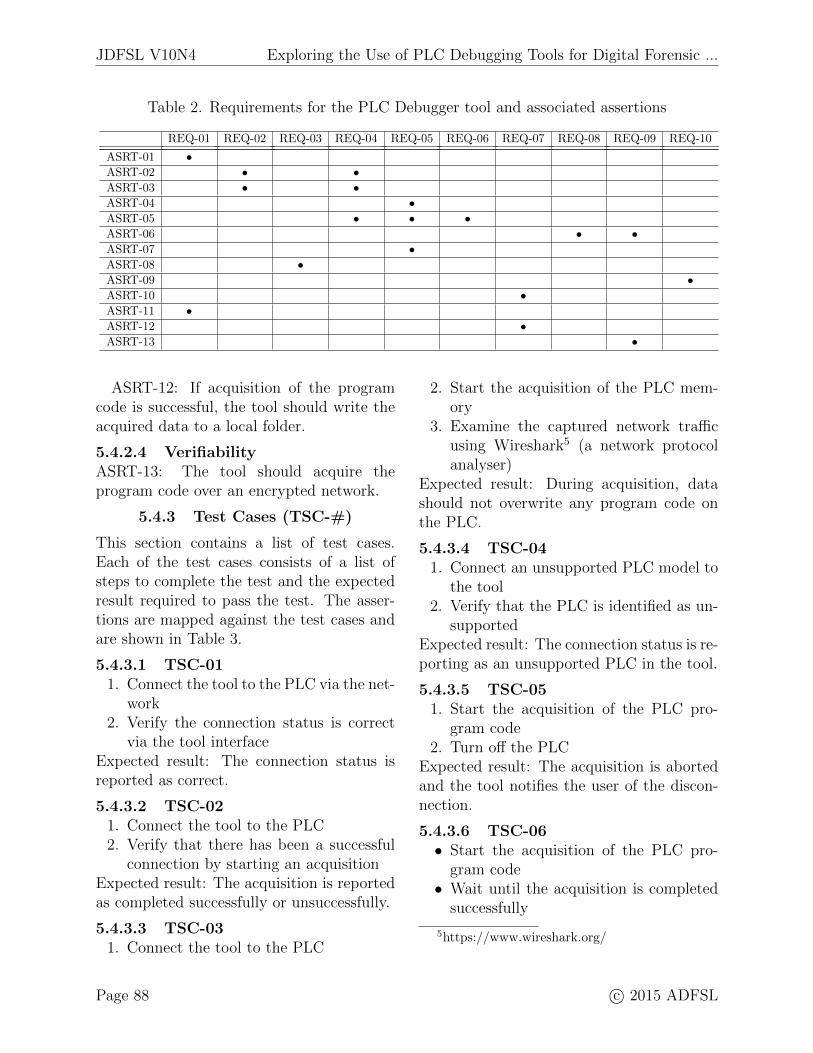
It is necessary that the tool is able toconnect to the PLC while it is operationaland through a network connection as thisis the main approach to acquire the PLC’sprogram code (REQ-01). In a real SCADAsystem there is no visible way to verify theconnection with the PLC, therefore the toolshould provide a method of verifying theconnection (REQ-02). The tool should beable to acquire the program code from thememory of the PLC (REQ-03). Errors inconnection or during acquisition should bereported to the user (REQ-04). The toolshould notify the user when the acquisitionhas been successful (REQ-05). The toolshould notify the user when the acquisitionhas been unsuccessful (REQ-06). The toolshould write the acquired data to a file, savedin various file formats when acquisition ofthe PLC’s program code is successful (REQ-07). The tool should not write any data tothe memory of the PLC (REQ-08). The toolshould acquire the data securely (REQ-09).The tool should automatically be able to ac-quire the memory addresses (REQ-10). Inthe next section we outline the assertions de-veloped based on the above requirements.
5.4.2 Assertions (ASRT-#)
The assertions have been categorised intofour main forensic properties these are; con-nectivity, accuracy, usability and verifiabil-ity. The assertions have been mapped withthe requirements and are shown in Table 2.
5.4.2.1 ConnectivityASRT-01: The connection between
the tool and the PLC should be madepossible through the network.
ASRT-02: If the connection between thetool and the PLC is successful, the toolshould notify the user.
ASRT-03: If the connection between thetool and the PLC is unsuccessful the toolshould notify the user.
ASRT-04: The tool should present ac-quired program code in a format useful toan digital forensic investigator.
ASRT-05: If the acquisition of the pro-gram code is successful or unsuccessful thetool should notify the user.
5.4.2.2 AccuracyASRT-06: The tool should not send
any data to modify the PLC program code.ASRT-07: The tool should accurately ac-
quire the program code. For example, ifthe program code contains 8 DBs and 9OB blocks, the tool should report this ac-curately.
5.4.2.3 UsabilityASRT-08: The tool should provide
the ability to allow the user to start theacquisition process.
ASRT-09: The acquisition of the programcode should be automatic after entering thememory addresses.
ASRT-10: The tool should record and savethe data in a format that can be later usedin analysis also storing timestamps.
ASRT-11: The tool should have the abil-ity to acquire data while the device is stilloperational.
ASRT-12: If acquisition of the programcode is successful, the tool should write theacquired data to a local folder.
5.4.2.4 VerifiabilityASRT-13: The tool should acquire theprogram code over an encrypted network.
5.4.3 Test Cases (TSC-#)
This section contains a list of test cases.Each of the test cases consists of a list ofsteps to complete the test and the expectedresult required to pass the test. The asser-tions are mapped against the test cases andare shown in Table 3.
5.4.3.1 TSC-011. Connect the tool to the PLC via the net-
work2. Verify the connection status is correct
via the tool interfaceExpected result: The connection status isreported as correct.
5.4.3.2 TSC-021. Connect the tool to the PLC2. Verify that there has been a successful
connection by starting an acquisitionExpected result: The acquisition is reportedas completed successfully or unsuccessfully.
5.4.3.3 TSC-031. Connect the tool to the PLC
2. Start the acquisition of the PLC mem-ory
3. Examine the captured network trafficusing Wireshark5 (a network protocolanalyser)
Expected result: During acquisition, datashould not overwrite any program code onthe PLC.
5.4.3.4 TSC-041. Connect an unsupported PLC model to
the tool2. Verify that the PLC is identified as un-
supportedExpected result: The connection status is re-porting as an unsupported PLC in the tool.
5.4.3.5 TSC-051. Start the acquisition of the PLC pro-
gram code2. Turn off the PLC
Expected result: The acquisition is abortedand the tool notifies the user of the discon-nection.
5.4.3.6 TSC-06• Start the acquisition of the PLC pro-
gram code• Wait until the acquisition is completed
Exploring the Use of PLC Debugging Tools for Digital Forensic ... JDFSL V10N4
• Export and save the acquired data to afile
Expected result: The tool saves the acquireddata to a file.
5.4.3.7 TSC-07• Connect a supported PLC to the tool• Enter the memory addresses to acquire• Use the tool to start the acquisition
Expected result: The acquisition is com-pleted successfully.
5.5 Limitations
There are several limitations in our exper-iments. Firstly, PLC Logger reads valuesover a network connection which would in-crease traffic overhead on the network. Fur-ther research would be required to establisheffects on industrial equipment.
Our experiments were limited to the useof a specific brand of Siemens PLC and onePLC debugging tool. However our experi-mental setup can be applied to other brandsof PLCs and other PLC debugging tools.
We based our experiment on one scenariowith the program code specifically developedfor these experiments and was not collectedfrom a real SCADA system. Therefore, ad-ditional testing would be required and pro-gram codes would need to be collected fromreal SCADA systems. We have developedour traffic light scenario for the experimentsas close as possible to model a real-life traf-fic light crossing. A real-life traffic light sce-nario will be more complex when comparedto our demonstration since ours is only asmall component of the traffic light system.PLC programming concepts are common toall manufacturers and differ in program lan-guages, I/O addressing, memory organisa-tion and instruction sets mean that they arenever perfectly interchangeable between dif-ferent makers, even products from the samemanufacturer may not be compatible.
6. RESULTS AND
DISCUSSIONIn this section, we present and discuss the re-sults from our experiments. The results fromtesting PLC Logger are presented. Then weused NIST’s CFTT framework to test PLCLogger to determine its suitability as a foren-sic acquisition and analysis tool for PLCs.
6.1 Experiment 1
In PLC Logger, the following are the mem-ory addresses that have output a value of1 (True): Pedestrian Red (Q0.3), Green(Q0.2), Start Light (M0.0), State0 (M0.1)and StartP (M0.6). This indicates the PLCis currently in State 0, with the TLs greenand the PLs red. Slight modifications weremade to the memory addresses in the pro-gram code, to cause both the TLs and PLsto turn green. PLC Logger was again usedto acquire the memory addresses and foundthat the following had been modified; Pedes-trian Red (Q0.3) outputs a value of 0 (False)and Pedestrian Green (Q0.4) of 1 (True).Thus, both TLs and PLs were showing green.
One of our research aims was to investi-gate whether the PLC program code can beof use in forensic investigations, for instanceto determine an attacker’s intentions. Theresults from the experiment indicate thatPLC Logger can be used to communicateand acquire data from the memory addressesof the PLC without any problems. In thisscenario, by acquiring the memory addressesfrom the PLC we were able to identify thatthe attacker had made slight modificationsto the memory addresses, allowing us to de-termine their intention. In this situationit would have been their intention to causeboth TLs and PLs to turn green, potentiallyto cause an accident, disrupt the flow of traf-fic flow or cause distress. The results fromExperiment 1 show the hypothesis was ac-cepted, as we were able to show that the
JDFSL V10N4 Exploring the Use of PLC Debugging Tools for Digital Forensic ...
program code was useful for a forensic in-vestigation by identifying the attacker’s in-tention. In the next section a methodologicalapproach is used to further test PLC Logger.
6.2 Experiment 2
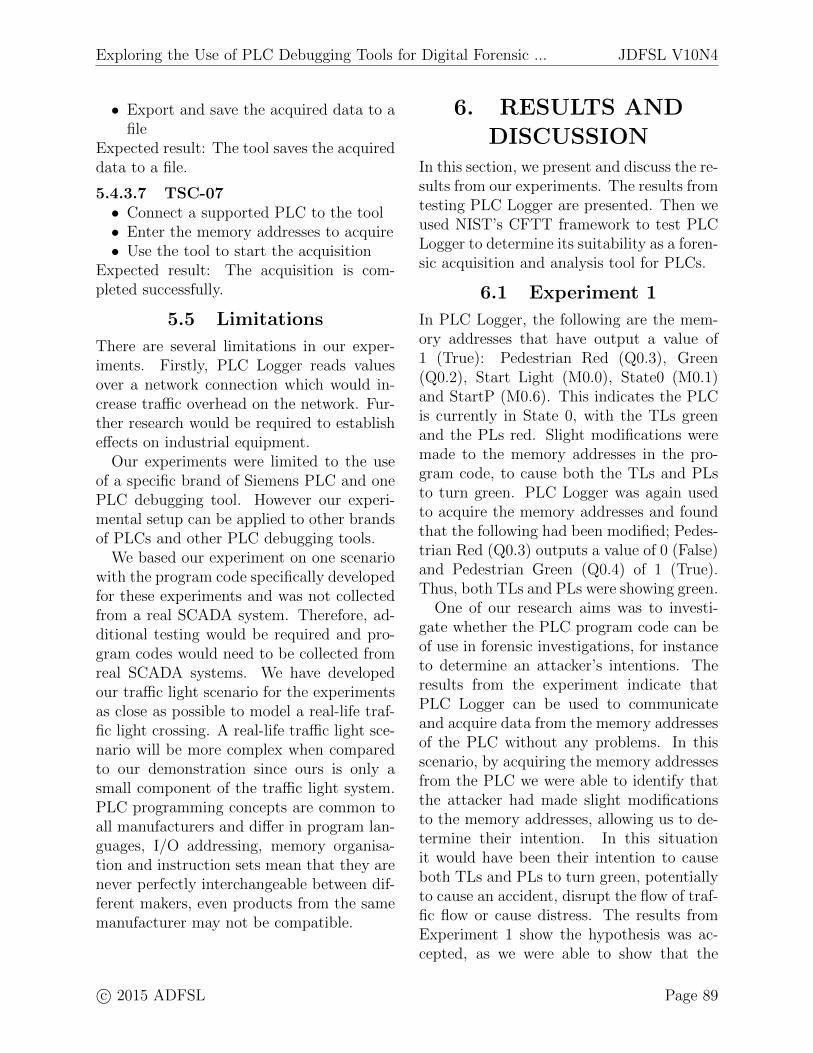
We used an existing CFTT framework toexplore the suitability as a forensic acqui-sition and analysis tool for PLCs. First,developing a set of requirements, assertionsand then test cases. Each test case consistsof the steps required to complete the testand the expected results needed to pass thetest. The reason for not using a numberinggrading scale as the one seen in (Anobah,Saleem, & Popov, 2014) is because it’s mainuse there was for the comparison of forensictools. Whereas our intention was to explorewhether PLC Logger was suitable forensictool for PLCs. An overview of the resultsare shown in Table 3.
The complete results can be found in Ap-pendix A; in this section only the main re-sults are discussed.
The test that failed was TSC-01 with theassertion ASRT-02 referring to the notifica-tion of successful connection between PLCLogger and the PLC if successful. The toolfailed this assertion as it does not notify theuser when the PLC is online or when an un-supported PLC is connected. We found thatwhen the wrong IP address of the PLC wasentered, the tool’s interface would display ared exclamation indicator. But this was thealso the case when a user had entered an in-correct memory address. This meant therewas no clear indication which was incorrectas it could either be the memory address, IPaddress or both.
TSC-04 with the assertion ASRT-03 refersto PLC Logger notifying the user when thePLC is disconnected from the network. Thetool failed the test as it does not notifythe user when the PLC is disconnected.It was identified the graphical interface in
PLC Logger continues to output the value 0,which could be an indication that the PLCis disconnected.
TSC-02 with the assertion ASRT-05, re-ferring to the PLC Logger notifying the userif the acquisition of the PLC is successful orunsuccessful. This assertion failed the test,as there are no notifications in the interfaceof PLC Logger until the user has input thecorrect IP address of the PLC and memoryaddresses. If these are not input correctlythe interface in PLC Logger remains at thedefault setting.
Assertions ASRT-01 to 05 showed it hadfailed on connectivity issues. However thesecan easily be overcome by implementing sim-ple features such as notifications to the userwhen a PLC has been disconnected fromPLC Logger.
In TSC-03 with the assertion ASRT-06,refers to PLC Logger making modificationsto the program code during acquisition. Thisassertion was to test for accuracy and failed,after examination of the captured networktraffic, it was not possible to determinewhether any modifications were made. Withany live forensic tool the investigator wouldwant to prevent modifications to the origi-nal data as much as possible to preserve theintegrity of the evidence. Therefore furtherresearch would be required on PLC Loggerto determine the type of data sent and re-ceived during the acquisition process on thePLC (Jones, 2007).
The next tests was TSC-02 with the as-sertion ASRT-07, referring to PLC Loggerreporting the complete program code. Thiswas to test for accuracy, however PLC Log-ger failed as it did not provide specific mem-ory addresses that can be entered into PLCLogger. A solution would be to use a combi-nation of PLC Logger and a Snap 7 Client. ASnap 7 Client 6 is used to communicate with
Exploring the Use of PLC Debugging Tools for Digital Forensic ... JDFSL V10N4
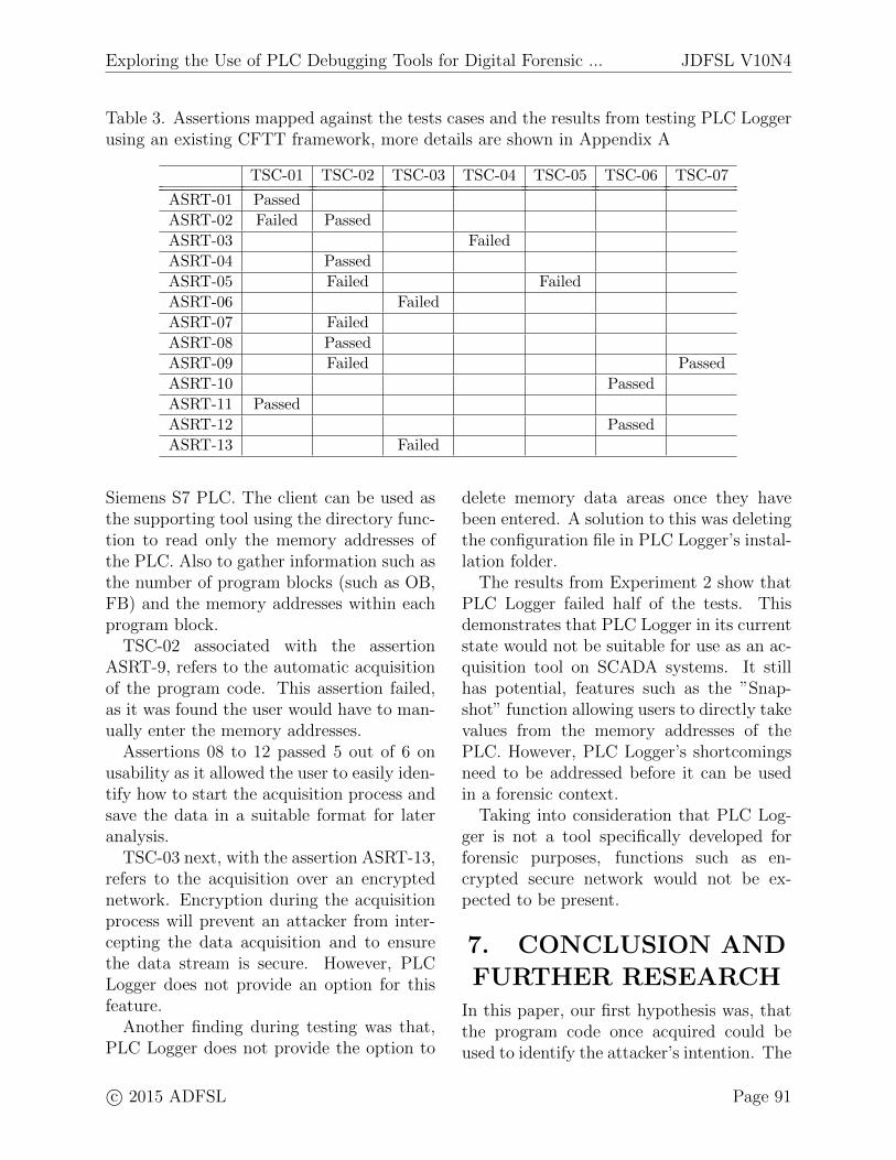
Table 3. Assertions mapped against the tests cases and the results from testing PLC Loggerusing an existing CFTT framework, more details are shown in Appendix A
TSC-01 TSC-02 TSC-03 TSC-04 TSC-05 TSC-06 TSC-07
ASRT-01 Passed
ASRT-02 Failed Passed
ASRT-03 Failed
ASRT-04 Passed
ASRT-05 Failed Failed
ASRT-06 Failed
ASRT-07 Failed
ASRT-08 Passed
ASRT-09 Failed Passed
ASRT-10 Passed
ASRT-11 Passed
ASRT-12 Passed
ASRT-13 Failed
Siemens S7 PLC. The client can be used asthe supporting tool using the directory func-tion to read only the memory addresses ofthe PLC. Also to gather information such asthe number of program blocks (such as OB,FB) and the memory addresses within eachprogram block.
TSC-02 associated with the assertionASRT-9, refers to the automatic acquisitionof the program code. This assertion failed,as it was found the user would have to man-ually enter the memory addresses.
Assertions 08 to 12 passed 5 out of 6 onusability as it allowed the user to easily iden-tify how to start the acquisition process andsave the data in a suitable format for lateranalysis.
TSC-03 next, with the assertion ASRT-13,refers to the acquisition over an encryptednetwork. Encryption during the acquisitionprocess will prevent an attacker from inter-cepting the data acquisition and to ensurethe data stream is secure. However, PLCLogger does not provide an option for thisfeature.
Another finding during testing was that,PLC Logger does not provide the option to
delete memory data areas once they havebeen entered. A solution to this was deletingthe configuration file in PLC Logger’s instal-lation folder.
The results from Experiment 2 show thatPLC Logger failed half of the tests. Thisdemonstrates that PLC Logger in its currentstate would not be suitable for use as an ac-quisition tool on SCADA systems. It stillhas potential, features such as the ”Snap-shot” function allowing users to directly takevalues from the memory addresses of thePLC. However, PLC Logger’s shortcomingsneed to be addressed before it can be usedin a forensic context.
Taking into consideration that PLC Log-ger is not a tool specifically developed forforensic purposes, functions such as en-crypted secure network would not be ex-pected to be present.
7. CONCLUSION AND
FURTHER RESEARCHIn this paper, our first hypothesis was, thatthe program code once acquired could beused to identify the attacker’s intention. The
JDFSL V10N4 Exploring the Use of PLC Debugging Tools for Digital Forensic ...
findings from Experiment 1 indicate our hy-pothesis was accepted and by using PLCLogger to acquire the program code, we wereable to extract useful forensic artefacts thatcould be useful in determining an attacker’sintention.
Our second, hypothesis was that PLCdebugging tools can be used as a foren-sic tool to acquire and analyse the pro-gram code from a PLC. In Experiment 2 weused NIST’s CFTT framework to establisha method for testing forensic tools for PLCsand also to understand the tool’s capabili-ties. The results showed this hypothesis wasrejected as PLC Logger had failed half ofthe tests. Considering PLC Logger was de-signed to be used for diagnostic purposes onPLCs, and not as a forensic tool, this couldbe viewed as a expected result.
The use of NIST’s CFTT frameworkwould be ideal for initial testing of other ac-quisition and analysis tools for PLCs. Help-ing to identify any possible problems withtools and whether it would be a suitable toolfor forensic investigations on SCADA sys-tems. The results from these experimentscan be used to improve PLC Logger for useas a forensic tool for SCADA systems. Theycan also be used as a specification for theinitial design of an acquisition tool.
Currently we have conducted all of ourexperiments only on the Siemens S7 PLC.PLC Logger also supports Modbus TCP/IP,therefore further research should be carriedout to determine whether it would be use-ful for other PLC brands. A practical prob-lem, because PLC Logger was developed byopen source developers, may at some pointchoose not to develop it further or fix bugsin the software. Further research would berequired to add the additional forensic fea-tures that were found to be missing duringthe tool testing experiments. For example,the encrypted secure network was one of themissing features. A next step in the research
would be to evaluate our research contribu-tions by comparing it against a tool withsimilar features.
Current research suggests that remote at-testation be implemented to solve the prob-lem of attacks manipulating the PLC pro-gram code. However this is theoretical andhas not been tested in practical experiments.It has been suggested that remote attesta-tion is weak, as a verifier cannot prove thatthe device has not been compromised onlythat it is working as expected (Valente, Bar-reto, & Cardenas, 2014).
ACKNOWLEDGEMENTSWe would like to thank EPSRC for the fund-ing of Tina Wu’s DPhil programme. Tinawould also like to thank Adrian Campos forteaching her how to program PLCs.
Exploring the Use of PLC Debugging Tools for Digital Forensic ... JDFSL V10N4
REFERENCESAhmed, I., Obermeier, S., Naedele, M., &
Richard, G. G. (2012). Scadasystems: Challenges for forensicinvestigators. Computer , 45 (12),44–51.
Anobah, M., Saleem, S., & Popov, O.(2014). Testing framework for mobiledevice forensics tools. Journal ofDigital Forensics, Security and Law ,9 (2), 221–234.
Basnight, Z. H. (2013). FirmwareCounterfeiting and ModificationAttacks on Programmable LogicControllers. Retrieved from http://
oai.dtic.mil/oai/oai?verb=
getRecord\&metadataPrefix=html\
&identifier=ADA583401
Carrier, B. (2003). Defining digital forensicexamination and analysis tools usingabstraction layers. InternationalJournal of digital evidence, 1 (4),1–12.
Clarke, N., Tryfonas, T., & Dodge, R.(2012). Proceedings of the 7thinternational workshop on digitalforensics and incident analysisWDFIA 2012. University ofPlymouth.
ENISA. (2013). Can we learn from scadasecurity incidents? (Tech. Rep.).Enisa.
Flandrin, F., Buchanan, W. J., Macfarlane,R., Ramsay, B., & Smales, A. (2014).Evaluating digital forensic tools(DFTs).
Jones, R. (2007). Safer live forensicacquisition. University of Kent .Retrieved fromhttps://www.cs.kent.ac.uk/pubs/
ug/2007/co620-projects/
forensic/report.pdf
Kilpatrick, T., Gonzalez, J., Chandia, R.,Papa, M., & Shenoi, S. (2006). Anarchitecture for SCADA networkforensics. Advances in DigitalForensics II , 222 , 273–285\r364.Retrieved from<GotoISI>://000240980400022
McLaughlin, S. (2011). On dynamicmalware payloads aimed atprogrammable logic controllers.Proceedings of the 6th USENIXconference on Hot topics in security.HotSec, 11 , 10.
NIST. (2007, December). General testmethodology for computer forensictools.
Patzlaff, H. (2013). D7.1 preliminary reporton forensic analysis for industrialsystems (Tech. Rep.). The CRISALISConsortium.
Radvanovsky, R., & Brodsky, J. (2013).Handbook of SCADA/control systemssecurity. Taylor & Francis. Retrievedfrom https://books.google.co.uk/
books?id=ukqGhkpOkdMC
Rick Ayers, W. J., Sam Brothers. (2013,September). Guidelines on mobiledevice forensics.
Taveras, P. (2013). SCADA live forensics:real time data acquisition process todetect, prevent or evaluate criticalsituations. European ScientificJournal , 9 (21).
Valente, J., Barreto, C., & Cardenas, A. a.(2014). Cyber-Physical SystemsAttestation. IEEE InternationalConference on Distributed Computingin Sensor Systems , 354–357.
Van der Knijff, R. M. (2014). Controlsystems/scada forensics, what’s thedifference? Digital Investigation. doi:
JDFSL V10N4 Exploring the Use of PLC Debugging Tools for Digital Forensic ...
10.1016/j.diin.2014.06.007Vidas, T. (2007). The acquisition and
analysis of random access memory.Journal of Digital Forensic Practice,1 (4), 315–323.
Zhu, B., Joseph, A., & Sastry, S. (2011). Ataxonomy of cyber attacks on scadasystems. In Proceedings of the 2011international conference on internetof things and 4th internationalconference on cyber, physical andsocial computing (pp. 380–388).
Exploring the Use of PLC Debugging Tools for Digital Forensic ... JDFSL V10N4
APPENDIX
A. TOOL TESTING
RESULTS
A.1 ASRT-01
A.1.1 TSC-01 [PASSED]
The tool was capable of using the networkthrough the PLC’s IP address to acquire thememory addresses stored on the PLC.
A.2 ASRT-02
A.2.1 TSC-01 [FAILED]
The tool does not provide the user with a no-tification when the connection to the PLC issuccessful
A.2.2 TSC-02 [PASSED]
The tool does not notify the user if the acqui-sition is successful however the tool providesgraphical visualisation that an connection hasbeen established and acquisition can be visu-alised in the tool.
A.3 ASRT-03
A.3.1 TSC-04 [FAILED]
The tool does not notify the user when the con-nection between the PLC and the tool is unsuc-cessful.
A.4 ASRT-04
A.4.1 TSC-02 [PASSED]
The tool outputs values within the memory ad-dresses with useful data that can be linked backto the program code. For example the toolwas able to determine whether the values in thememory addresses were either True or False
A.5 ASRT-05
A.5.1 TSC-02 [FAILED]
The tool does not notify user if the acquisitionis successful or unsuccessful. However it wasidentified if an memory area added that is not
within the memory range of the PLC then a redexclamation is shown in PLC Logger
A.5.2 TSC-05 [FAILED]
The tool does not notify the user when the PLCis disconnected from the network. This canviewed in the graphical visualisation to whetherthe memory addresses are outputting any values
A.6 ASRT-06
A.6.1 TSC-03 [FAILED]
After examining the captured network trafficbetween the PLC and PLC Logger it was unde-termined whether there were any modificationswere made during live acquisition.
A.7 ASRT-07
A.7.1 TSC-02 [FAILED]
The tool only allows the user to view the mem-ory addresses but is unable to allow the user toview the number of program blocks within theprogram code
A.8 ASRT-08
A.8.1 TSC-02 [PASSED]
The tool has a button labelled with a ”Play”button and allows the user to start data cap-turing based on the customised configurations
A.9 ASRT-09
A.9.1 TSC-02 [FAILED]
The tool requires some input from the user, inorder to be able to acquire data from the mem-ory addresses the user would need to manuallyenter each memory address as the tool does notautomatically detect the memory addresses inthe PLC.
A.9.2 TSC-07 [PASSED]
Once the memory addresses are entered into thetool the acquisition process can be completed
JDFSL V10N4 Exploring the Use of PLC Debugging Tools for Digital Forensic ...
A.10 ASRT-10
A.10.1 TSC-06 [PASSED]
The tool provided the option to export the datain two formats MySQL and CSV files. The toolsuccessfully allows the user to save the files tobe used later for further analysis including thetimestamps.
A.11 ASRT-11
A.11.1 TSC-01 [PASSED]
The tool is capable of acquiring data over thenetwork while the PLC is online
A.12 ASRT-12
A.12.1 TSC-06 [PASSED]
The tool was capable of saving the acquireddata to a local folder
A.13 ASRT-13
A.13.1 TSC-03 [FAILED]
The tool does not provide an option to allow theuser to have an encrypted secure acquisition


![Debugging with gdb · Debugging Data Race Conditions: Section 12.2 [Data Race Detection], page 171. Debugging OpenMP*: Section 12.4 [OpenMP* Debugging], page 177. Extended recording](https://static.documents.pub/doc/80x56/5f0b5c707e708231d4302334/debugging-with-gdb-debugging-data-race-conditions-section-122-data-race-detection.jpg)


