10 Explosion-protected motors Part 2/3 Part 3 Type of explosion protection “n” (increased safety “ec”) / Protection by enclosure “tb”, “tc” Overview of technical data 10/156 Motor selection data 10/157 IE3-W4.R for Premium Efficiency IE3 IE2-WE..R for High Efficiency IE2 (IE1-)K..R, K2.. for Standard Efficiency IE1 Bearings Identical to bearings of standard motors, see Chapter 2 Terminal boxes 10/195 Dimensions 10/198 Contents Part 1 Product description 10/2 Increased safety „e“ („eb“) Overview of technical data 10/7 Motor selection data 10/8 IE3-K..R for Premium Efficiency IE3 IE2-K..R for High Efficiency IE2 K..R without efficiency classification K11R for converter-fed operation Bearings 10/45 Terminal boxes 10/55 Dimensions 10/58 Part 2 Flameproof enclosure “d/de” (“db/db eb”) Overview of technical data 10/124 Motor selection data 10/125 (IE3-)K8.R… (Y3) for Premium Efficiency IE3 (IE2-)K8.R… (Y2) for High Efficiency IE2 K8.R… for Standard Efficiency IE1 B82R… with built-in brake B82R… with built-in brake, pole-changing K82R… with built-on brake Bearings 10/138 Terminal boxes 10/140 Dimensions 10/144
Transcript
10
Explosion-protectedmotors Part 2/3
Part 3
Type of explosion protection “n” (increased safety “ec”) /Protection by enclosure “tb”, “tc”Overview of technical data 10/156Motor selection data 10/157
IE3-W4.R for Premium Efficiency IE3IE2-WE..R for High Efficiency IE2(IE1-)K..R, K2.. for Standard Efficiency IE1
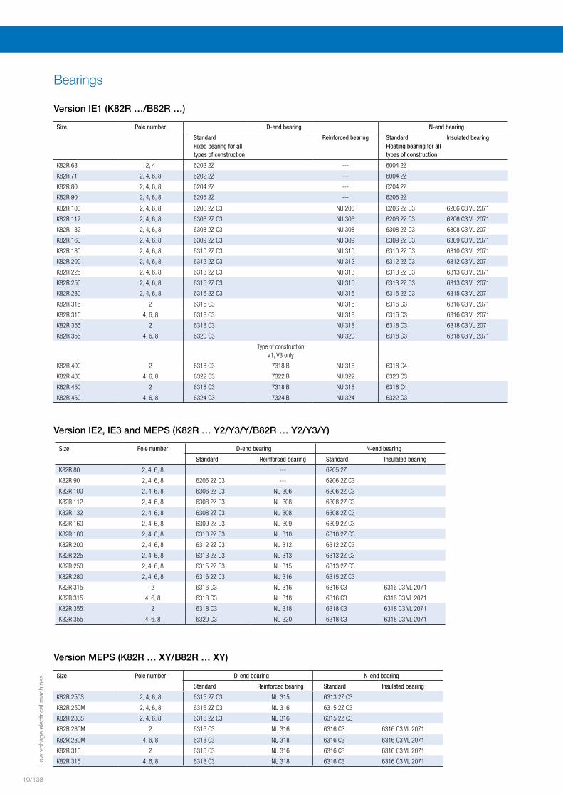
BearingsIdentical to bearings of standard motors,see Chapter 2
Terminal boxes 10/195
Dimensions 10/198
Contents
Part 1
Product description 10/2
Increased safety „e“ („eb“)Overview of technical data 10/7Motor selection data 10/8
IE3-K..R for Premium Efficiency IE3IE2-K..R for High Efficiency IE2K..R without efficiency classificationK11R for converter-fed operation
Bearings 10/45
Terminal boxes 10/55
Dimensions 10/58
Part 2
Flameproof enclosure “d/de” (“db/db eb”) Overview of technical data 10/124Motor selection data 10/125
(IE3-)K8.R… (Y3) for Premium Efficiency IE3(IE2-)K8.R… (Y2) for High Efficiency IE2K8.R… for Standard Efficiency IE1
B82R… with built-in brakeB82R… with built-in brake, pole-changingK82R… with built-on brake
Bearings 10/138
Terminal boxes 10/140
Dimensions 10/144
Low
vol
tage
ele
ctric
al m
achi
nes
10/124
Product group Squirrel-cage rotor, IEC/DINExplosion protection type Flameproof enclosure „d/de“ („db/db eb“) Rated output Ex d/de (Ex db/db eb) (IE.) – K8.R, 0.12 to 730 kWSizes Ex d/de (Ex db/db eb) (IE.) – K8.R, 63 to 450Housing material Grey cast ironRated torque 0.6 Nm to 5770 NmEfficiency classification/ efficiency determination
IEC/EN 60034-30-1 / IEC/EN 60034-2-1, ≤ 1 kW direct measurement,> 1 kW residual loss method
Method of connection Single-speed motors are designed in star-delta configurationas standard.
Stator winding insulation Thermal class 155, optional 155 [F(B)], 180 to IEC/EN 60034-1Degree of protection IP 55
to IEC/EN 60034-5 Type of cooling IC 411, IC 416, IC 71W (IC 31W)
to IEC/EN 60034-6 Coolant temperature/ installation altitude
Standard -20 °C to +40 °C,Deviating coolant temperatures upon requestAltitude 1000 m above sea level
Rated voltage Standard voltages to EN 60038 50 Hz: 230 V, 400 V, 500 V, 690 V, 60 Hz: 275 V, 460 V, 480 V, 600 V
Duty types Continuous duty S1, converter-fed operation S9Types of construction IM B3, IM B35, IM B5 and derived types
to IEC/EN 60034-7Paint finish Normal finish “Morderate”, colour RAL 7031, blue-grey
Special finish “Worldwide”, colour RAL 7031, blue-greyVibration severity grade Grade “A” as standard for machines with no special vibration
requirementsShaft ends to DIN 748 (IEC 60072), balanced with half-keyLimit speeds Please refer to the section of “Limit speeds“ in catalogue section
“Motors for converter-fed operation”, Chapter 4.Bearing design Please refer to the tables of bearing design data. Motor mass Please refer to the technical selection lists.Terminal boxes Please refer to the section “Terminal boxes”.Documentation An operating and maintenance manual, a terminal plan and
a safety data sheet are supplied with each motor.Tolerances Please refer to the section “Tolerances” in catalogue section
“Introduction“, Chapter 1.Options Please refer to the section “Overview of modifications” in catalogue
section “Introduction“, Chapter 1.
Overview of technical dataThe most important technical data are summarised in the following table.Further information can be taken from the catalogue section “Introduction” (Chapter 1).
Low
vol
tage
ele
ctric
al m
achi
nes
10
10/125
Three-phase motors with squirrel-cage rotor, Premium Efficiency IE3 II 2G Ex d/de IIC T4 Gb
Type of explosion protection – Flameproof enclosure „d/de“ („db/db eb“) for operation in Zone 1 according to EN 60079-1
for rated voltage, temperature class T4 with surface cooling, duty type S1, continuous duty thermal class F, degree of protection IP 55, 50 Hz
Motor selection data Design point 400 V, 50 HzType PB MB nB hB cosjB IB IA/IB MA/MB MK/MB ATEX no. J m
400 VkW Nm rpm % - A - - - kgm2 kg
Synchronous speed 3000 rpm – 2-pole versionEfficiency according to manufacturer standard
K82R 63 M2 Ex de IIC T4 0.18 0.6 2905 66 0.67 0.59 6.8 4.6 6.5 PTB 09 ATEX 1017 X 0.00028 16K82R 63 MX2 Ex de IIC T4 0.25 0.8 2860 70 0.75 0.69 5.8 3.4 4.7 PTB 09 ATEX 1017 X 0.00028 16K82R 71 M2 Ex de IIC T4 0.37 1.3 2800 71.5 0.84 0.89 5.2 2.7 3.5 PTB 09 ATEX 1017 X 0.00028 16K82R 71 MX2 Ex de IIC T4 0.55 1.9 2810 72 0.82 1.34 5.5 2.8 3.6 PTB 09 ATEX 1017 X 0.00039 17
Efficiency according to IEC/EN 60034-30-1IE3-K82R 80 M2 Ex de IIC T4 0.75 2.48 2890 IE3- 82.8 0.87 1.5 6.6 3 3.6 PTB 16 ATEX 1002 X 0.0013 31IE3-K82R 80 MX2 Ex de IIC T4 1.1 3.64 2885 IE3- 83.7 0.87 2.2 6.5 2.9 3.5 PTB 16 ATEX 1002 X 0.0018 35IE3-K82R 90 S2 Ex de IIC T4 1.5 4.95 2895 IE3- 84.7 0.88 2.9 6.8 3 3.5 PTB 16 ATEX 1002 X 0.0029 45IE3-K82R 90 L2 Ex de IIC T4 2.2 7.2 2900 IE3- 86.4 0.88 4.2 6.9 3 3.6 PTB 16 ATEX 1002 X 0.0039 48IE3-K82R 100 L2 Ex de IIC T4 3 9.8 2910 IE3- 88.1 0.88 5.6 6.9 2.5 2.9 PTB 16 ATEX 1003 X 0.0051 53IE3-K82R 112 M2 Ex de IIC T4 4 13 2930 IE3- 88.4 0.87 7.5 6.9 2.8 3.6 PTB 16 ATEX 1003 X 0.0089 95IE3-K82R 132 S2 Ex de IIC T4 5.5 18 2925 IE3- 89.5 0.89 10 7 2.5 3.3 PTB 16 ATEX 1004 X 0.0125 103IE3-K82R 132 SX2 Ex de IIC T4 7.5 24.4 2930 IE3- 90.3 0.89 13.5 7.1 2.7 3.5 PTB 16 ATEX 1004 X 0.0177 115K82R 160 M2 Ex de IIC T4 Y3 11 35.7 2940 IE3- 91.3 0.87 20 7.3 3 3.6 PTB 09 ATEX 1018 X 0.032 163K82R 160 MX2 Ex de IIC T4 Y3 15 48.7 2940 IE3- 92 0.9 26 7.2 2.8 3.2 PTB 09 ATEX 1018 X 0.043 173K82R 160 L2 Ex de IIC T4 Y3 18.5 60 2940 IE3- 92.5 0.91 31.5 7.2 2.7 3.1 PTB 09 ATEX 1018 X 0.052 188K82R 180 M2 Ex de IIC T4 Y3 22 71 2945 IE3- 92.9 0.91 37.5 7.5 2.6 3.2 PTB 09 ATEX 1018 X 0.075 196K82R 200 L2 Ex de IIC T4 Y3 30 97 2955 IE3- 93.5 0.9 51 7.5 2.7 3.1 PTB 09 ATEX 1019 X 0.13 254K82R 200 LX2 Ex de IIC T4 Y3 37 120 2955 IE3- 93.8 0.9 63 7.6 2.8 3.2 PTB 09 ATEX 1020 X 0.16 278K82R 225 M2 Ex de IIC T4 Y3 45 145 2960 IE3- 94.2 0.9 77 7.3 2.7 3 PTB 09 ATEX 1020 X 0.24 400K82R 250 M2 Ex de IIC T4 Y3 55 177 2970 IE3- 94.4 0.88 96 7.5 2.8 3.1 PTB 09 ATEX 1018 X 0.4 545K82R 280 S2 Ex de IIC T4 Y3 75 241 2975 IE3- 94.8 0.88 130 7.1 2.3 2.8 PTB 09 ATEX 1018 X 0.65 700K82R 280 M2 Ex de IIC T4 Y3 90 288 2980 IE3- 95.1 0.87 157 7.4 2.4 2.9 PTB 09 ATEX 1018 X 0.78 762K82R 315 S2 Ex de IIC T4 Y3 110 353 2975 IE3- 95.4 0.89 187 7.1 2.2 2.6 PTB 09 ATEX 1018 X 1.4 960K82R 315 M2 Ex de IIC T4 Y3 132 424 2975 IE3- 95.8 0.9 220 6.8 2.1 2.5 PTB 09 ATEX 1018 X 1.6 1025K82R 315 L2 Ex de IIC T4 Y3 160 514 2980 IE3- 95.9 0.9 270 7.4 2.4 2.7 PTB 09 ATEX 1018 X 1.7 1065K82R 315 LX2 Ex de IIC T4 Y3 200 614 2980 IE3- 96 0.9 335 6.9 2.3 2.6 PTB 09 ATEX 1018 X 2.2 1270K82R 315 LY2 Ex de IIC T4 Y3 250 801 2980 IE3- 96 0.92 410 7.2 1.7 2.7 PTB 09 ATEX 1018 X 2.8 1420K82R 355 L2 Ex de IIC T4 Y3 315 1009 2980 IE3- 96.6 0.92 510 6.7 1.5 2.8 PTB 09 ATEX 1021 X 4.5 1900K82R 355 LX2 Ex de IIC T4 Y3 355 1136 2985 IE3- 96.8 0.93 570 6.9 1.4 2.7 PTB 09 ATEX 1021 X 5 2050
Efficiency according to manufacturer standardK82R 355 LX2 Ex de IIC T4 400 1280 2985 96.8 0.93 640 7 1.3 2.8 5.5 2350K82R 400 L2 Ex de IIC T4 450 1437 2990 97 0.94 710 7.2 1.1 2.8 8.5 2910
Motor selection data
Low
vol
tage
ele
ctric
al m
achi
nes
10/126
Motor selection data
Three-phase motors with squirrel-cage rotor, Premium Efficiency IE3 II 2G Ex d/de IIC T4 Gb
Type of explosion protection – Flameproof enclosure „d/de“ („db/db eb“) for operation in Zone 1 according to EN 60079-1
for rated voltage, temperature class T4 with surface cooling, duty type S1, continuous duty thermal class F, degree of protection IP 55, 50 Hz
Motor selection data Design point 400 V, 50 HzType PB MB nB hB cosjB IB IA/IB MA/MB MK/MB ATEX no. J m
400 VkW Nm rpm % - A - - - kgm2 kg
Synchronous speed 1500 rpm – 4-pole versionEfficiency according to manufacturer standard
K82R 63 M4 Ex de IIC T4 0.12 0.8 1445 67 0.60 0.43 5.6 3.9 3.9 PTB 09 ATEX 1017 X 0.00046 16K82R 63 MX4 Ex de IIC T4 0.18 1.2 1415 70 0.70 0.53 4.7 2.7 2.7 PTB 09 ATEX 1017 X 0.00046 16K82R 71 M4 Ex de IIC T4 0.25 1.7 1370 68.5 0.80 0.66 3.9 2 2.3 PTB 09 ATEX 1017 X 0.00046 16K82R 71 MX4 Ex de IIC T4 0.37 2.6 1380 71 0.80 0.94 3.9 2.2 2.3 PTB 09 ATEX 1017 X 0.00063 17K82R 80 M4 Ex de IIC T4 0.55 3.8 1380 72 0.80 1.36 3.8 2 2.3 PTB 09 ATEX 1018 X 0.00092 24
Efficiency according to IEC/EN 60034-30-1IE3-K82R 80 MX4 Ex de IIC T4 0.75 5 1445 IE3- 82.6 0.78 1.68 6.8 3.2 4.2 PTB 16 ATEX 1002 X 0.0029 35IE3-K82R 90 S4 Ex de IIC T4 1.1 7.2 1455 IE3- 84.2 0.8 2.35 6.8 2.4 3.1 PTB 16 ATEX 1002 X 0.0046 44IE3-K82R 90 L4 Ex de IIC T4 1.5 9.9 1450 IE3- 85.5 0.81 3.15 6.9 2.5 3.2 PTB 16 ATEX 1002 X 0.0056 46IE3-K82R 100 L4 Ex de IIC T4 2.2 14.5 1450 IE3- 87.1 0.84 4.35 7.3 2.9 3.3 PTB 16 ATEX 1003 X 0.011 59IE3-K82R 100 LX4 Ex de IIC T4 3 18.8 1450 IE3- 87.8 0.84 5.9 7.4 3.1 3.6 PTB 16 ATEX 1003 X 0.011 59IE3-K82R 112 M4 Ex de IIC T4 4 26.2 1460 IE3- 88.7 0.83 7.8 7.2 3 3.4 PTB 16 ATEX 1003 X 0.022 100IE3-K82R 132 S4 Ex de IIC T4 5.5 36 1460 IE3- 89.6 0.85 10.4 7.1 3.2 3.5 PTB 16 ATEX 1004 X 0.03 113IE3-K82R 132 M4 Ex de IIC T4 7.5 49 1460 IE3- 90.5 0.86 13.9 7.4 3.1 3.3 PTB 16 ATEX 1004 X 0.041 125K82R 160 M4 Ex de IIC T4 Y3 11 71 1470 IE3- 91.5 0.85 20.5 7.1 2.8 3.1 PTB 09 ATEX 1018 X 0.079 184K82R 160 L4 Ex de IIC T4 Y3 15 97 1470 IE3- 92.1 0.83 28.5 7.4 3.1 3.4 PTB 09 ATEX 1018 X 0.092 208K82R 180 M4 Ex de IIC T4 Y3 18.5 120 1470 IE3- 92.7 0.83 34.5 7.4 3.3 3.4 PTB 09 ATEX 1018 X 0.155 217K82R 180 L4 Ex de IIC T4 Y3 22 143 1470 IE3- 93.2 0.83 41 7.4 3.3 3.3 PTB 09 ATEX 1019 X 0.197 272K82R 200 L4 Ex de IIC T4 Y3 30 195 1470 IE3- 93.8 0.85 54 7.6 3.1 3.3 PTB 09 ATEX 1019 X 0.25 274K82R 225 S4 Ex de IIC T4 Y3 37 240 1475 IE3- 93.9 0.85 67 7.1 3 2.9 PTB 09 ATEX 1020 X 0.4 372K82R 225 M4 Ex de IIC T4 Y3 45 291 1475 IE3- 94.3 0.86 80 7.2 3.1 3 PTB 09 ATEX 1018 X 0.48 402K82R 250 M4 Ex de IIC T4 Y3 55 356 1475 IE3- 94.6 0.88 95 7.3 3.1 3 PTB 09 ATEX 1018 X 0.75 588K82R 280 S4 Ex de IIC T4 Y3 75 484 1480 IE3- 95.2 0.85 134 7.4 3 2.8 PTB 09 ATEX 1018 X 1.25 740K82R 280 M4 Ex de IIC T4 Y3 90 579 1485 IE3- 95.3 0.85 160 7.8 3.2 3 PTB 09 ATEX 1018 X 1.48 820K82R 315 S4 Ex de IIC T4 Y3 110 707 1485 IE3- 95.6 0.84 198 6.9 2.7 2.7 PTB 09 ATEX 1018 X 2.2 1040K82R 315 M4 Ex de IIC T4 Y3 132 849 1485 IE3- 95.8 0.84 235 7 2.7 2.7 PTB 09 ATEX 1018 X 2.7 1120K82R 315 L4 Ex de IIC T4 Y3 160 1026 1490 IE3- 96 0.84 285 7.4 2.8 2.8 PTB 09 ATEX 1018 X 3.1 1210K82R 315 LX4 Ex de IIC T4 Y3 200 1286 1490 IE3- 96.1 0.85 355 6.9 2.6 2.6 PTB 09 ATEX 1018 X 3.9 1430K82R 315 LY4 Ex de IIC T4 Y3 250 1602 1490 IE3- 96.2 0.87 430 7.3 1.7 2.7 PTB 09 ATEX 1018 X 4.6 1565K82R 355 L4 Ex de IIC T4 Y3 315 2019 1490 IE3- 96.3 0.9 525 6.9 1.5 2.7 PTB 09 ATEX 1018 X 6.1 2050K82R 355 LX4 Ex de IIC T4 Y3 355 2275 1490 IE3- 96.6 0.9 590 6.9 1.6 2.8 PTB 09 ATEX 1021 X 6.7 2200
Efficiency according to manufacturer standardK82R 355 LY4 Ex de IIC T4 400 2564 1490 97 0.90 665 7 1.5 2.8 PTB 09 ATEX 1021 X 7.4 2430K82R 400 M4 Ex de IIC T4 450 2875 1495 97 0.91 735 7.3 1.1 2.7 PTB 09 ATEX 1022 X 18 2850K82R 400 L4 Ex de IIC T4 500 3194 1495 97.1 0.91 815 7.3 1.1 2.7 PTB 09 ATEX 1022 X 20 3230K82R 450 M4 Ex de IIC T4 560 3577 1495 97.2 0.91 915 6.8 1 2.7 PTB 09 ATEX 1023 X 26 3500K82R 450 L4 Ex de IIC T4 630 4024 1495 97.4 0.91 1025 6.8 1 2.7 PTB 09 ATEX 1023 X 31 3800
Low
vol
tage
ele
ctric
al m
achi
nes
10
10/127
Three-phase motors with squirrel-cage rotor, Premium Efficiency IE3 II 2G Ex d/de IIC T4 Gb
Type of explosion protection – Flameproof enclosure „d/de“ („db/db eb“) for operation in Zone 1 according to EN 60079-1
for rated voltage, temperature class T4 with surface cooling, duty type S1, continuous duty thermal class F, degree of protection IP 55, 50 Hz
Motor selection data Design point 400 V, 50 HzType PB MB nB hB cosjB IB IA/IB MA/MB MK/MB ATEX no. J m
400 VkW Nm rpm % - A - - - kgm2 kg
Synchronous speed 1000 rpm – 6-pole versionEfficiency according to manufacturer standard
K82R 71 MX6 Ex de IIC T4 0.25 2.6 920 62 0.71 0.82 3.5 2.2 2.6 PTB 09 ATEX 1017 X 0.0012 17K82R 80 M6 Ex de IIC T4 0.37 3.8 925 67 0.71 1.12 4.1 2.5 2.8 PTB 09 ATEX 1018 X 0.0019 24K82R 80 MX6 Ex de IIC T4 0.55 5.7 925 69 0.72 1.6 4 2.4 2.7 PTB 09 ATEX 1018 X 0.0025 25
Efficiency according to IEC/EN 60034-30-1IE3-K82R 90 S6 Ex de IIC T4 0.75 7.5 955 IE3- 79.1 0.7 1.96 5.5 2.7 3.1 PTB 16 ATEX 1002 X 0.008 44IE3-K82R 90 L6 Ex de IIC T4 1.1 11 955 IE3- 81.4 0.72 2.7 5.9 2.8 3.1 PTB 16 ATEX 1002 X 0.0095 46IE3-K82R 100 L6 Ex de IIC T4 1.5 14.8 965 IE3- 83.5 0.71 3.65 6.8 3 3.3 PTB 16 ATEX 1003 X 0.017 59IE3-K82R 112 M6 Ex de IIC T4 2.2 21.8 965 IE3- 85.5 0.78 4.75 6.8 2.6 3.1 PTB 16 ATEX 1003 X 0.031 100IE3-K82R 132 S6 Ex de IIC T4 3 29.5 970 IE3- 85.7 0.74 6.8 7.1 3.2 3.7 PTB 16 ATEX 1004 X 0.031 100IE3-K82R 132 M6 Ex de IIC T4 4 39.6 965 IE3- 87 0.76 8.7 6.9 2.9 3.7 PTB 16 ATEX 1004 X 0.037 104IE3-K82R 132 MX6 Ex de IIC T4 5.5 54 965 IE3- 88.3 0.81 11.1 7.2 2.7 3.4 PTB 16 ATEX 1004 X 0.048 117K82R 160 M6 Ex de IIC T4 Y3 7.5 74 970 IE3- 89.4 0.84 14.4 7.5 2.8 3.8 PTB 09 ATEX 1018 X 0.12 190K82R 160 L6 Ex de IIC T4 Y3 11 108 975 IE3- 90.5 0.84 21 7.6 3 3.9 PTB 09 ATEX 1018 X 0.14 220K82R 180 L6 Ex de IIC T4 Y3 15 147 975 IE3- 91.5 0.82 29 7.4 2.7 3.8 PTB 09 ATEX 1019 X 0.19 215K82R 200 L6 Ex de IIC T4 Y3 18.5 181 975 IE3- 92 0.83 35 7 2.5 3.5 PTB 09 ATEX 1020 X 0.28 270K82R 200 LX6 Ex de IIC T4 Y3 22 215 975 IE3- 92.4 0.84 41 6.9 2.2 3.2 PTB 09 ATEX 1020 X 0.31 280K82R 225 M6 Ex de IIC T4 Y3 30 291 985 IE3- 93 0.83 56 6.9 3 2.7 PTB 09 ATEX 1018 X 0.69 404K82R 250 M6 Ex de IIC T4 Y3 37 359 985 IE3- 93.5 0.83 69 6.8 3 2.7 PTB 09 ATEX 1018 X 1.03 570K82R 280 S6 Ex de IIC T4 Y3 45 434 990 IE3- 93.9 0.82 84 6.6 2.8 2.4 PTB 09 ATEX 1018 X 1.35 720K82R 280 M6 Ex de IIC T4 Y3 55 533 985 IE3- 94.4 0.81 104 6.5 2.8 2.4 PTB 09 ATEX 1018 X 1.7 770K82R 315 S6 Ex de IIC T4 Y3 75 723 990 IE3- 94.9 0.88 130 7.2 3 2.7 PTB 09 ATEX 1018 X 4.3 995K82R 315 M6 Ex de IIC T4 Y3 90 868 990 IE3- 95.2 0.88 155 7.7 3.2 2.8 PTB 09 ATEX 1018 X 5 1050K82R 315 L6 Ex de IIC T4 Y3 110 1061 990 IE3- 95.5 0.88 189 7.8 3.3 2.8 PTB 09 ATEX 1018 X 6 1145K82R 315 LX6 Ex de IIC T4 Y3 132 1273 990 IE3- 95.6 0.88 225 7.7 3.2 2.8 PTB 09 ATEX 1018 X 7.3 1265K82R 315 LY6 Ex de IIC T4 Y3 160 1543 990 IE3- 95.8 0.88 275 7.8 3.3 2.8 PTB 09 ATEX 1018 X 8.3 1440K82R 355 M6 Ex de IIC T4 Y3 200 1929 990 IE3- 95.9 0.87 345 6.7 1.8 2.7 PTB 09 ATEX 1021 X 11.3 1750K82R 355 L6 Ex de IIC T4 Y3 250 2411 990 IE3- 95.9 0.88 430 6.7 1.8 2.7 PTB 09 ATEX 1021 X 13.8 1950K82R 355 LX6 Ex de IIC T4 Y3 315 3039 990 IE3- 96 0.88 540 6.9 1.7 2.6 PTB 09 ATEX 1021 X 17.6 2300K82R 400 M6 Ex de IIC T4 Y3 355 3411 990 IE3- 96.6 0.89 595 6.6 1.1 2.7 PTB 09 ATEX 1022 X 21 2850
Efficiency according to manufacturer standardK82R 400 L6 Ex de IIC T4 400 3843 994 96.6 0.89 670 6.8 1.1 2.6 PTB 09 ATEX 1022 X 31 3230K82R 450 M6 Ex de IIC T4 450 4319 995 96.6 0.89 755 6.8 1.2 2.8 PTB 09 ATEX 1023 X 46 3500K82R 450 L6 Ex de IIC T4 500 4799 995 97 0.89 835 6.8 1.1 2.7 PTB 09 ATEX 1023 X 51 3800
Low
vol
tage
ele
ctric
al m
achi
nes
10/128
Motor selection data
Three-phase motors with squirrel-cage rotor, High Efficiency IE2 II 2G Ex d/de IIC T4 Gb
Type of explosion protection – Flameproof enclosure „d/de“ („db/db eb“) for operation in Zone 1 according to EN 60079-1 for rated voltage, temperature class T4 with surface cooling, duty type S1, continuous duty thermal class F, degree of protection IP 55, 50 Hz
Motor selection data Design point 400 V, 50 HzType PB MB nB hB cosjB IB IA/IB MA/MB MK/MB ATEX no. J m
400 VkW Nm rpm % - A - - - kgm2 kg
Synchronous speed 3000 rpm – 2-pole versionEfficiency according to manufacturer standard
K82R 63 M2 Ex de IIC T4 0.18 0.6 2905 66 0.67 0.59 6.8 4.6 6.5 PTB 09 ATEX 1017 X 0.00028 16K82R 63 MX2 Ex de IIC T4 0.25 0.8 2860 70 0.75 0.69 5.8 3.4 4.7 PTB 09 ATEX 1017 X 0.00028 16K82R 71 M2 Ex de IIC T4 0.37 1.3 2800 71.5 0.84 0.89 5.2 2.7 3.5 PTB 09 ATEX 1017 X 0.00028 16K82R 71 MX2 Ex de IIC T4 0.55 1.9 2810 72 0.82 1.34 5.5 2.8 3.6 PTB 09 ATEX 1017 X 0.00039 17
Efficiency according to IEC/EN 60034-30-1IE2-K82R 80 M2 Ex de IIC T4 0.75 2.48 2890 IE2- 79 0.87 1.58 6.6 3 3.6 PTB 16 ATEX 1002 X 0.0013 31IE2-K82R 80 MX2 Ex de IIC T4 1.1 3.64 2885 IE2- 81.1 0.87 2.25 6.5 2.9 3.5 PTB 16 ATEX 1002 X 0.0018 35IE2-K82R 90 S2 Ex de IIC T4 1.5 4.95 2895 IE2- 82.7 0.88 3 6.8 3 3.5 PTB 16 ATEX 1002 X 0.0029 45IE2-K82R 90 L2 Ex de IIC T4 2.2 7.2 2900 IE2- 84.5 0.88 4.25 6.9 3 3.6 PTB 16 ATEX 1002 X 0.0039 48IE2-K82R 100 L2 Ex de IIC T4 3 9.8 2910 IE2- 85.8 0.88 5.7 6.9 2.5 2.9 PTB 16 ATEX 1003 X 0.0051 53IE2-K82R 112 M2 Ex de IIC T4 4 13 2930 IE2- 86.9 0.87 7.6 6.9 2.8 3.6 PTB 16 ATEX 1003 X 0.0089 95IE2-K82R 132 S2 Ex de IIC T4 5.5 18 2925 IE2- 88.1 0.89 10.1 7 2.5 3.3 PTB 16 ATEX 1004 X 0.0125 103IE2-K82R 132 SX2 Ex de IIC T4 7.5 24.4 2930 IE2- 89.1 0.89 13.7 7.1 2.7 3.5 PTB 16 ATEX 1004 X 0.0177 115K82R 160 M2 Ex de IIC T4 Y2 11 35.7 2940 IE2- 90.3 0.87 20 7.3 3 3.6 PTB 09 ATEX 1018 X 0.032 163K82R 160 MX2 Ex de IIC T4 Y2 15 48.7 2940 IE2- 91.1 0.9 26.5 7.2 2.8 3.2 PTB 09 ATEX 1018 X 0.043 173K82R 160 L2 Ex de IIC T4 Y2 18.5 60 2940 IE2- 91.6 0.91 32 7.2 2.7 3.1 PTB 09 ATEX 1018 X 0.052 188K82R 180 M2 Ex de IIC T4 Y2 22 71 2945 IE2- 92 0.91 38 7.5 2.6 3.2 PTB 09 ATEX 1018 X 0.075 196K82R 200 L2 Ex de IIC T4 Y2 30 97 2955 IE2- 92.7 0.9 52 7.5 2.7 3.1 PTB 09 ATEX 1019 X 0.13 254K82R 200 LX2 Ex de IIC T4 Y2 37 120 2955 IE2- 93.3 0.91 63 7.2 2.7 3 PTB 09 ATEX 1020 X 0.16 278K82R 225 M2 Ex de IIC T4 Y2 45 145 2960 IE2- 93.4 0.9 77 7.3 2.7 3 PTB 09 ATEX 1020 X 0.24 400K82R 250 M2 Ex de IIC T4 Y2 55 177 2970 IE2- 93.8 0.89 95 7.1 2.4 2.8 PTB 09 ATEX 1018 X 0.4 545K82R 280 S2 Ex de IIC T4 Y2 75 241 2970 IE2- 94.5 0.9 129 6.8 2.2 2.7 PTB 09 ATEX 1018 X 0.65 700K82R 280 M2 Ex de IIC T4 Y2 90 288 2970 IE2- 94.7 0.89 152 6.8 2.4 2.8 PTB 09 ATEX 1018 X 0.78 762K82R 315 S2 Ex de IIC T4 Y2 110 353 2975 IE2- 95 0.89 188 6.5 2 2.4 PTB 09 ATEX 1018 X 1.4 960K82R 315 M2 Ex de IIC T4 Y2 132 424 2975 IE2- 95.5 0.89 225 6.8 2.1 2.5 PTB 09 ATEX 1018 X 1.6 1025K82R 315 L2 Ex de IIC T4 Y2 160 514 2975 IE2- 95.7 0.9 270 6.9 2.4 2.7 PTB 09 ATEX 1018 X 1.7 1065K82R 315 LX2 Ex de IIC T4 Y2 200 614 2980 IE2- 95.8 0.9 335 6.9 2.3 2.6 PTB 09 ATEX 1018 X 2.2 1270K82R 315 LY2 Ex de IIC T4 Y2 250 801 2980 IE2- 96 0.92 410 7.2 1.7 2.7 PTB 09 ATEX 1018 X 2.8 1420K82R 355 L2 Ex de IIC T4 Y2 315 1009 2980 IE2- 96.6 0.92 510 6.7 1.5 2.8 PTB 09 ATEX 1021 X 4.5 1900K82R 355 LX2 Ex de IIC T4 Y2 355 1036 2985 IE2- 96.8 0.93 570 6.9 1.4 2.7 PTB 09 ATEX 1021 X 5 2050
Efficiency according to manufacturer standard (IEC/EN 60034-2)K82R 355 LY2 Ex de IIC T4 400 1280 2985 96.8 0.94 640 7 1.3 2.8 PTB 09 ATEX 1021 X 5.5 2350K82R 400 L2 Ex de IIC T4 450 1437.3 2990 97 0.94 710 7.2 1.1 2.8 PTB 09 ATEX 1022 X 8.5 2910
Low
vol
tage
ele
ctric
al m
achi
nes
10
10/129
Three-phase motors with squirrel-cage rotor, High Efficiency IE2 II 2G Ex d/de IIC T4 Gb
Type of explosion protection – Flameproof enclosure „d/de“ („db/db eb“)for operation in Zone 1 according to EN 60079-1
for rated voltage, temperature class T4 with surface cooling, duty type S1, continuous duty thermal class F, degree of protection IP 55, 50 Hz
Motor selection data Design point 400 V, 50 HzType PB MB nB hB cosjB IB IA/IB MA/MB MK/MB ATEX no. J m
400 VkW Nm rpm % - A - - - kgm2 kg
Synchronous speed 1500 rpm – 4-pole versionEfficiency according to manufacturer standard
K82R 63 M4 Ex de IIC T4 0.12 0.8 1445 67 0.60 0.43 5.6 3.9 3.9 PTB 09 ATEX 1017 X 0.00046 16K82R 63 MX4 Ex de IIC T4 0.18 1.2 1415 70 0.70 0.53 4.7 2.7 2.7 PTB 09 ATEX 1017 X 0.00046 16K82R 71 M4 Ex de IIC T4 0.25 1.7 1370 68.5 0.80 0.66 3.9 2 2.3 PTB 09 ATEX 1017 X 0.00046 16K82R 71 MX4 Ex de IIC T4 0.37 2.6 1380 71 0.80 0.94 3.9 2.2 2.3 PTB 09 ATEX 1017 X 0.00063 17K82R 80 M4 Ex de IIC T4 0.55 3.8 1380 72 0.80 1.36 3.8 2 2.3 PTB 09 ATEX 1018 X 0.00092 24
Efficiency according to IEC/EN 60034-30-1IE2-K82R 80 MX4 Ex de IIC T4 0.75 5 1445 IE2- 81 0.78 1.71 6.8 3.2 4.2 PTB 16 ATEX 1002 X 0.0029 35IE2-K82R 90 S4 Ex de IIC T4 1.1 7.2 1455 IE2- 82.7 0.8 2.4 6.8 2.4 3.1 PTB 16 ATEX 1002 X 0.0046 44IE2-K82R 90 L4 Ex de IIC T4 1.5 9.9 1450 IE2- 84 0.81 3.2 6.9 2.5 3.2 PTB 16 ATEX 1002 X 0.0056 46IE2-K82R 100 L4 Ex de IIC T4 2.2 14.5 1450 IE2- 85.5 0.84 4.4 7.3 2.9 3.3 PTB 16 ATEX 1003 X 0.011 59IE2-K82R 100 LX4 Ex de IIC T4 3 18.8 1450 IE2- 86.6 0.84 6 7.4 3.1 3.6 PTB 16 ATEX 1003 X 0.011 59IE2-K82R 112 M4 Ex de IIC T4 4 26.2 1460 IE2- 87.6 0.83 7.9 7.2 3 3.4 PTB 16 ATEX 1003 X 0.022 100IE2-K82R 132 S4 Ex de IIC T4 5.5 36 1460 IE2- 88.6 0.85 10.5 7.1 3.2 3.5 PTB 16 ATEX 1004 X 0.03 113IE2-K82R 132 M4 Ex de IIC T4 7.5 49 1460 IE2- 89.5 0.86 14.1 7.4 3.1 3.3 PTB 16 ATEX 1004 X 0.041 125K82R 160 M4 Ex de IIC T4 Y2 11 71 1470 IE2- 90.6 0.85 20.5 7.1 2.8 3.1 PTB 09 ATEX 1018 X 0.079 184K82R 160 L4 Ex de IIC T4 Y2 15 97 1470 IE2- 91.3 0.83 28.5 7.4 3 3.3 PTB 09 ATEX 1018 X 0.083 187K82R 180 M4 Ex de IIC T4 Y2 18.5 120 1470 IE2- 91.9 0.83 35 7.4 3.3 3.4 PTB 09 ATEX 1018 X 0.155 217K82R 180 L4 Ex de IIC T4 Y2 22 143 1470 IE2- 92.3 0.83 41.5 7.3 3.3 3.3 PTB 09 ATEX 1019 X 0.164 225K82R 200 L4 Ex de IIC T4 Y2 30 195 1470 IE2- 92.9 0.85 55 7.6 3.1 3.3 PTB 09 ATEX 1019 X 0.25 274K82R 225 S4 Ex de IIC T4 Y2 37 240 1475 IE2- 93.3 0.85 67 7.1 3 2.9 PTB 09 ATEX 1020 X 0.4 372K82R 225 M4 Ex de IIC T4 Y2 45 291 1475 IE2- 93.6 0.86 81 7.2 3.1 3 PTB 09 ATEX 1018 X 0.48 402K82R 250 M4 Ex de IIC T4 Y2 55 356 1475 IE2- 94 0.88 96 7.3 3.1 3 PTB 09 ATEX 1018 X 0.75 588K82R 280 S4 Ex de IIC T4 Y2 75 484 1480 IE2- 94.5 0.85 135 7.4 3 2.8 PTB 09 ATEX 1018 X 1.25 740K82R 280 M4 Ex de IIC T4 Y2 90 579 1485 IE2- 94.7 0.85 161 7.8 3.2 3 PTB 09 ATEX 1018 X 1.48 820K82R 315 S4 Ex de IIC T4 Y2 110 707 1485 IE2- 95.1 0.85 196 6.7 2.5 2.5 PTB 09 ATEX 1018 X 2.2 1040K82R 315 M4 Ex de IIC T4 Y2 132 849 1485 IE2- 95.3 0.85 235 6.8 2.6 2.6 PTB 09 ATEX 1018 X 2.7 1120K82R 315 L4 Ex de IIC T4 Y2 160 1026 1485 IE2- 95.6 0.86 280 6.9 2.7 2.6 PTB 09 ATEX 1018 X 3.1 1210K82R 315 LX4 Ex de IIC T4 Y2 200 1286 1485 IE2- 95.8 0.86 350 6.9 2.7 2.6 PTB 09 ATEX 1018 X 3.9 1430K82R 315 LY4 Ex de IIC T4 Y2 250 1602 1490 IE2- 96.2 0.87 430 7.3 1.7 2.7 PTB 09 ATEX 1018 X 4.6 1565K82R 355 L4 Ex de IIC T4 Y2 315 2019 1490 IE2- 96.3 0.9 525 6.9 1.5 2.7 PTB 09 ATEX 1018 X 6.1 2050K82R 355 LX4 Ex de IIC T4 Y2 355 2275 1490 IE2- 96.6 0.9 590 6.9 1.6 2.8 PTB 09 ATEX 1021 X 6.7 2200
Efficiency according to manufacturer standardK82R 355 LY4 Ex de IIC T4 400 2564 1490 97 0.90 665 7 1.5 2.8 PTB 09 ATEX 1021 X 7.4 2430K82R 400 M4 Ex de IIC T4 450 2875 1495 97 0.91 735 7.3 1.1 2.7 PTB 09 ATEX 1022 X 18 2850K82R 400 L4 Ex de IIC T4 500 3194 1495 97.1 0.91 815 7.3 1.1 2.7 PTB 09 ATEX 1022 X 20 3230K82R 450 M4 Ex de IIC T4 560 3577 1495 97.2 0.91 915 6.8 1 2.7 PTB 09 ATEX 1023 X 26 3500K82R 450 L4 Ex de IIC T4 630 4024 1495 97.4 0.91 1025 6.8 1 2.7 PTB 09 ATEX 1023 X 31 3800
Low
vol
tage
ele
ctric
al m
achi
nes
10/130
Motor selection data
Three-phase motors with squirrel-cage rotor, High Efficiency IE2 II 2G Ex d/de IIC T4 Gb
Type of explosion protection – Flameproof enclosure „d/de“ („db/db eb“) for operation in Zone 1 according to EN 60079-1 for rated voltage, temperature class T4 with surface cooling, duty type S1, continuous duty thermal class F, degree of protection IP 55, 50 Hz
Motor selection data Design point 400 V, 50 HzType PB MB nB hB cosjB IB IA/IB MA/MB MK/MB ATEX no. J m
400 VkW Nm rpm % - A - - - kgm2 kg
Synchronous speed 1000 rpm – 6-pole versionEfficiency according to manufacturer standard
K82R 71 MX6 Ex de IIC T4 0.25 2.6 920 62 0.71 0.82 3.5 2.2 2.6 PTB 09 ATEX 1017 X 0.0012 17K82R 80 M6 Ex de IIC T4 0.37 3.8 925 67 0.71 1.12 4.1 2.5 2.8 PTB 09 ATEX 1018 X 0.0019 24K82R 80 MX6 Ex de IIC T4 0.55 5.7 925 69 0.72 1.6 4 2.4 2.7 PTB 09 ATEX 1018 X 0.0025 25
Efficiency according to IEC/EN 60034-30-1IE2-K82R 90 S6 Ex de IIC T4 0.75 7.5 955 IE2- 77.4 0.7 2 5.5 2.7 3.1 PTB 16 ATEX 1002 X 0.0080 44IE2-K82R 90 L6 Ex de IIC T4 1.1 11 955 IE2- 79.5 0.72 2.75 5.9 2.8 3.1 PTB 16 ATEX 1002 X 0.0095 46IE2-K82R 100 L6 Ex de IIC T4 1.5 14.8 965 IE2- 81.1 0.71 3.75 6.8 3 3.3 PTB 16 ATEX 1003 X 0.017 59IE2-K82R 112 M6 Ex de IIC T4 2.2 21.8 965 IE2- 83 0.78 4.9 6.8 2.6 3.1 PTB 16 ATEX 1003 X 0.031 100IE2-K82R 132 S6 Ex de IIC T4 3 29.5 970 IE2- 84.4 0.74 6.9 7.1 3.2 3.7 PTB 16 ATEX 1004 X 0.031 100IE2-K82R 132 M6 Ex de IIC T4 4 39.6 965 IE2- 85.7 0.76 8.9 6.9 2.9 3.7 PTB 16 ATEX 1004 X 0.037 104IE2-K82R 132 MX6 Ex de IIC T4 5.5 54 965 IE2- 87 0.81 11.3 7.2 2.7 3.4 PTB 16 ATEX 1004 X 0.048 117K82R 160 M6 Ex de IIC T4 Y2 7.5 74 970 IE2- 88.1 0.84 14.6 7.5 2.8 3.8 PTB 09 ATEX 1018 X 0.12 190K82R 160 L6 Ex de IIC T4 Y2 11 108 975 IE2- 89.5 0.81 22 7.6 2.9 3.9 PTB 09 ATEX 1018 X 0.12 190K82R 180 L6 Ex de IIC T4 Y2 15 147 975 IE2- 90.4 0.82 29 7.4 2.7 3.8 PTB 09 ATEX 1019 X 0.19 215K82R 200 L6 Ex de IIC T4 Y2 18.5 181 975 IE2- 91 0.83 35.5 7 2.5 3.5 PTB 09 ATEX 1020 X 0.28 270K82R 200 LX6 Ex de IIC T4 Y2 22 215 975 IE2- 91.5 0.84 41.5 6.9 2.2 3.2 PTB 09 ATEX 1020 X 0.31 280K82R 225 M6 Ex de IIC T4 Y2 30 291 985 IE2- 92.3 0.83 57 6.9 3 2.7 PTB 09 ATEX 1018 X 0.69 404K82R 250 M6 Ex de IIC T4 Y2 37 359 985 IE2- 92.7 0.83 69 6.8 3 2.7 PTB 09 ATEX 1018 X 1.03 570K82R 280 S6 Ex de IIC T4 Y2 45 434 985 IE2- 93.5 0.83 84 5.8 2.8 2.4 PTB 09 ATEX 1018 X 1.35 720K82R 280 M6 Ex de IIC T4 Y2 55 533 985 IE2- 93.6 0.82 103 5.8 2.7 2.3 PTB 09 ATEX 1018 X 1.7 770K82R 315 S6 Ex de IIC T4 Y2 75 723 990 IE2- 94.1 0.88 131 7.2 3 2.7 PTB 09 ATEX 1018 X 4.3 995K82R 315 M6 Ex de IIC T4 Y2 90 868 990 IE2- 94.4 0.88 156 7.7 3.2 2.8 PTB 09 ATEX 1018 X 5 1050K82R 315 L6 Ex de IIC T4 Y2 110 1061 990 IE2- 94.7 0.88 191 7.8 3.3 2.8 PTB 09 ATEX 1018 X 6 1145K82R 315 LX6 Ex de IIC T4 Y2 132 1273 990 IE2- 95 0.88 230 7.7 3.2 2.8 PTB 09 ATEX 1018 X 7.3 1265K82R 315 LY6 Ex de IIC T4 Y2 160 1543 990 IE2- 95.2 0.88 275 7.8 3.3 2.8 PTB 09 ATEX 1018 X 8.3 1440K82R 355 M6 Ex de IIC T4 Y2 200 1929 990 IE2- 95.5 0.88 345 6.7 1.8 2.7 PTB 09 ATEX 1021 X 11.3 1750K82R 355 L6 Ex de IIC T4 Y2 250 2411 990 IE2- 95.9 0.88 430 6.7 1.8 2.7 PTB 09 ATEX 1021 X 13.8 1950K82R 355 LX6 Ex de IIC T4 Y2 315 3039 990 IE2- 96 0.88 540 6.9 1.7 2.6 PTB 09 ATEX 1021 X 17.6 2300K82R 400 M6 Ex de IIC T4 Y2 355 3411 994 IE2- 96.6 0.89 595 6.6 1.7 2.7 PTB 09 ATEX 1022 X 27 2850
Efficiency according to manufacturer standardK82R 400 L 6 Ex de IIC T4 400 3843 994 96.6 0.89 670 6.8 1.1 2.6 PTB 09 ATEX 1022 X 31 3230K82R 450 M 6 Ex de IIC T4 450 4319 995 96.6 0.89 755 6.8 1.2 2.8 PTB 09 ATEX 1023 X 46 3500K82R 450 L6 Ex de IIC T4 500 4799 995 97 0.89 835 6.8 1.1 2.7 PTB 09 ATEX 1023 X 51 3800
Low
vol
tage
ele
ctric
al m
achi
nes
10
10/131
Motor selection data Design point 400 V, 50 HzType PB MB nB hB cosjB IB IA/IB MA/MB MK/MB ATEX no. J m
400 VkW Nm rpm % - A - - - kgm2 kg
Synchronous speed 3000 rpm – 2-pole version
K82R 63 M2 Ex de IIC T4 0.18 0.6 2905 66 0.67 0.59 6.8 4.6 6.5 PTB 09 ATEX 1017 X 0.00028 16K82R 63 MX2 Ex de IIC T4 0.25 0.8 2860 70 0.75 0.69 5.8 3.4 4.7 PTB 09 ATEX 1017 X 0.00028 16K82R 71 M2 Ex de IIC T4 0.37 1.3 2800 71.5 0.84 0.89 5.2 2.7 3.5 PTB 09 ATEX 1017 X 0.00028 16K82R 71 MX2 Ex de IIC T4 0.55 1.9 2810 72 0.82 1.34 5.5 2.8 3.6 PTB 09 ATEX 1017 X 0.00039 17K82R 80 M2 Ex de IIC T4 0.75 2.6 2790 IE1- 74.5 0.84 1.73 4.8 2.7 3.3 PTB 09 ATEX 1018 X 0.00058 24K82R 80 MX2 Ex de IIC T4 1.1 3.7 2820 IE1- 78 0.82 2.5 5.5 2.8 3.5 PTB 09 ATEX 1018 X 0.0008 25K82R 90 S2 Ex de IIC T4 1.5 5 2840 IE1- 77 0.86 3.25 5.9 2.9 3.2 PTB 09 ATEX 1018 X 0.0013 31K82R 90 L2 Ex de IIC T4 2.2 7.4 2850 IE1- 82 0.85 4.55 6.3 3 3.5 PTB 09 ATEX 1018 X 0.0018 35K82R 100 L2 Ex de IIC T4 3 10 2850 IE1- 82 0.87 6.1 6.8 2.7 3.3 PTB 09 ATEX 1018 X 0.0029 45K82R 112 M2 Ex de IIC T4 4 13 2880 IE1- 85 0.88 7.7 6.5 2.3 3.1 PTB 09 ATEX 1018 X 0.0051 53K82R 132 S2 Ex de IIC T4 5.5 18 2880 IE1- 85.5 0.87 10.7 6.4 2.5 3.3 PTB 09 ATEX 1018 X 0.0089 95K82R 132 SX2 Ex de IIC T4 7.5 25 2910 IE1- 86.5 0.87 14.4 6.8 2.7 3.5 PTB 09 ATEX 1018 X 0.0125 100K82R 160 M2 Ex de IIC T4 11 36 2925 IE1- 89 0.89 20 6.6 2.8 3.2 PTB 09 ATEX 1018 X 0.032 163K82R 160 MX2 Ex de IIC T4 15 49 2920 IE1- 89 0.91 26.5 6.8 2.8 3.2 PTB 09 ATEX 1018 X 0.043 173K82R 160 L2 Ex de IIC T4 18.5 60 2925 IE1- 90.5 0.92 32 6.8 2.6 3.1 PTB 09 ATEX 1018 X 0.052 188K82R 180 M2 Ex de IIC T4 22 72 2925 IE1- 91.5 0.92 37.5 6.9 2.5 3 PTB 09 ATEX 1019 X 0.075 196K82R 200 L2 Ex de IIC T4 30 97 2955 IE1- 92.5 0.90 52 7.2 2.6 2.9 PTB 09 ATEX 1020 X 0.13 254K82R 200 LX2 Ex de IIC T4 37 120 2955 IE1- 93.3 0.91 63 7.2 2.7 3 PTB 09 ATEX 1020 X 0.16 278K82R 225 M2 Ex de IIC T4 45 145 2960 IE1- 93 0.89 78 7.1 2.5 3 PTB 09 ATEX 1018 X 0.24 400K82R 250 M2 Ex de IIC T4 55 177 2970 IE1- 93.8 0.89 95 7.1 2.4 2.8 PTB 09 ATEX 1018 X 0.4 545K82R 280 S2 Ex de IIC T4 75 241 2970 IE1- 94.5 0.89 129 6.8 2.2 2.7 PTB 09 ATEX 1018 X 0.65 700K82R 280 M2 Ex de IIC T4 90 289 2970 IE1- 94.7 0.9 152 6.8 2.4 2.8 PTB 09 ATEX 1018 X 0.78 762K82R 315 S2 Ex de IIC T4 110 353 2975 IE1- 95 0.89 188 6.5 2 2.4 PTB 09 ATEX 1018 X 1.4 960K82R 315 M2 Ex de IIC T4 132 424 2975 IE1- 95.5 0.89 225 6.8 2.1 2.5 PTB 09 ATEX 1018 X 1.6 1025K82R 315 L2 Ex de IIC T4 160 514 2975 IE1- 95.7 0.90 270 6.9 2.4 2.7 PTB 09 ATEX 1018 X 1.9 1065K82R 315 LX2 Ex de IIC T4 200 641 2980 IE1- 95.8 0.90 335 6.9 2.3 2.6 PTB 09 ATEX 1018 X 2.2 1270K82R 315 LY2 Ex de IIC T4 250 801 2980 IE1- 96 0.92 410 7.2 1.7 2.7 PTB 09 ATEX 1018 X 2.8 1420K82R 355 L2 Ex de IIC T4 315 1009 2980 IE1- 96.6 0.92 510 6.7 1.5 2.8 PTB 09 ATEX 1021 X 4.5 1900K82R 355 LX2 Ex de IIC T4 355 1136 2985 IE1- 96.8 0.93 570 6.9 1.4 2.7 PTB 09 ATEX 1021 X 5 2050K82R 355 LY2 Ex de IIC T4 400 1280 2985 96.8 0.94 640 7 1.3 2.8 PTB 09 ATEX 1021 X 5.5 2350K82R 400 L2 Ex de IIC T4 450 1437 2990 97 0.94 710 7.2 1.1 2.8 PTB 09 ATEX 1022 X 8.5 2910
Three-phase motors with squirrel-cage rotor, Standard Efficiency IE1 II 2G Ex d/de IIC T4 Gb
Type of explosion protection – Flameproof enclosure „d/de“ („db/db eb“)for operation in Zone 1 according to EN 60079-1
for rated voltage, temperature class T4 with surface cooling, duty type S1, continuous duty thermal class F, degree of protection IP 55, 50 Hz
Low
vol
tage
ele
ctric
al m
achi
nes
10/132
Motor selection data
Three-phase motors with squirrel-cage rotor, Standard Efficiency IE1 II 2G Ex d/de IIC T4 Gb
Type of explosion protection – Flameproof enclosure „d/de“ („db/db eb“) for operation in Zone 1 according to EN 60079-1
for rated voltage, temperature class T4 with surface cooling, duty type S1, continuous duty thermal class F, degree of protection IP 55, 50 Hz
Motor selection data Design point 400 V, 50 HzType PB MB nB hB cosjB IB IA/IB MA/MB MK/MB ATEX no. J m
400 VkW Nm rpm % - A - - - kgm2 kg
Synchronous speed 1500 rpm – 4-pole version
K82R 63 M4 Ex de IIC T4 0.12 0.8 1445 67 0.60 0.43 5.6 3.9 3.9 PTB 09 ATEX 1017 X 0.00046 16K82R 63 MX4 Ex de IIC T4 0.18 1.2 1415 70 0.70 0.53 4.7 2.7 2.7 PTB 09 ATEX 1017 X 0.00046 16K82R 71 M4 Ex de IIC T4 0.25 1.7 1370 68.5 0.80 0.66 3.9 2 2.3 PTB 09 ATEX 1017 X 0.00046 16K82R 71 MX4 Ex de IIC T4 0.37 2.6 1380 71 0.80 0.94 3.9 2.2 2.3 PTB 09 ATEX 1017 X 0.00063 17K82R 80 M4 Ex de IIC T4 0.55 3.8 1380 72 0.80 1.36 3.8 2 2.3 PTB 09 ATEX 1018 X 0.00092 24K82R 80 MX4 Ex de IIC T4 0.75 5.1 1400 IE1- 75.5 0.79 1.81 4.5 2.1 2.5 PTB 09 ATEX 1018 X 0.0013 25K82R 90 S4 Ex de IIC T4 1.1 7.5 1400 IE1- 76 0.83 2.55 4.8 2.1 2.5 PTB 09 ATEX 1018 X 0.0021 31K82R 90 L4 Ex de IIC T4 1.5 10 1405 IE1- 79 0.82 3.35 5 2.3 2.7 PTB 09 ATEX 1018 X 0.0029 35K82R 100 L4 Ex de IIC T4 2.2 15 1420 IE1- 80 0.8 4.95 5.4 2.4 2.8 PTB 09 ATEX 1018 X 0.0046 44K82R 100 LX4 Ex de IIC T4 3 20 1415 IE1- 81.7 0.82 6.5 5.5 2.3 2.7 PTB 09 ATEX 1018 X 0.0056 46K82R 112 M4 Ex de IIC T4 4 27 1435 IE1- 85 0.84 8.1 6.8 2.7 3.2 PTB 09 ATEX 1018 X 0.011 59K82R 132 S4 Ex de IIC T4 5.5 36 1440 IE1- 86.5 0.85 10.8 6.4 2.5 2.7 PTB 09 ATEX 1018 X 0.022 100K82R 132 M4 Ex de IIC T4 7.5 50 1440 IE1- 88 0.86 14.3 6.5 2.7 2.8 PTB 09 ATEX 1018 X 0.03 110K82R 160 M4 Ex de IIC T4 11 72 1460 IE1- 89.5 0.85 21 6.6 2.5 2.8 PTB 09 ATEX 1018 X 0.057 168K82R 160 L4 Ex de IIC T4 15 98 1455 IE1- 90 0.86 28 6.7 2.8 3.1 PTB 09 ATEX 1018 X 0.079 184K82R 180 M4 Ex de IIC T4 18.5 121 1460 IE1- 91 0.84 35 6.7 2.9 3 PTB 09 ATEX 1019 X 0.13 198K82R 180 L4 Ex de IIC T4 22 144 1460 IE1- 91.5 0.84 41.5 6.9 3 3 PTB 09 ATEX 1019 X 0.155 217K82R 200 L4 Ex de IIC T4 30 196 1460 IE1- 92.5 0.88 53 6.8 2.6 2.9 PTB 09 ATEX 1020 X 0.25 274K82R 225 S4 Ex de IIC T4 37 241 1465 IE1- 93 0.88 65 6.7 2.7 2.6 PTB 09 ATEX 1018 X 0.4 372K82R 225 M4 Ex de IIC T4 45 292 1470 IE1- 93.5 0.88 79 6.5 2.7 2.6 PTB 09 ATEX 1018 X 0.48 402K82R 250 M4 Ex de IIC T4 55 357 1470 IE1- 93.8 0.89 95 7.1 2.9 2.9 PTB 09 ATEX 1018 X 0.75 573K82R 280 S4 Ex de IIC T4 75 484 1480 IE1- 94 0.86 134 6.8 2.6 2.5 PTB 09 ATEX 1018 X 1.25 740K82R 280 M4 Ex de IIC T4 90 581 1480 IE1- 94.5 0.86 160 6.9 2.8 2.6 PTB 09 ATEX 1018 X 1.48 820K82R 315 S4 Ex de IIC T4 110 707 1485 IE1- 95.1 0.85 196 6.7 2.5 2.5 PTB 09 ATEX 1018 X 2.2 1040K82R 315 M4 Ex de IIC T4 132 849 1485 IE1- 95.3 0.85 235 6.8 2.6 2.6 PTB 09 ATEX 1018 X 2.7 1120K82R 315 L4 Ex de IIC T4 160 1029 1485 IE1- 95.6 0.86 280 6.9 2.7 2.6 PTB 09 ATEX 1018 X 3.1 1210K82R 315 LX4 Ex de IIC T4 200 1286 1485 IE1- 95.8 0.86 350 6.9 2.7 2.6 PTB 09 ATEX 1018 X 3.9 1430K82R 315 LY4 Ex de IIC T4 250 1602 1490 IE1- 96.2 0.87 430 7.3 1.7 2.7 PTB 09 ATEX 1018 X 4.6 1565K82R 355 L4 Ex de IIC T4 315 2019 1490 IE1- 96.3 0.9 525 6.9 1.5 2.7 PTB 09 ATEX 1021 X 6.1 2050K82R 355 LX4 Ex de IIC T4 355 2275 1490 IE1- 96.6 0.90 590 6.9 1.6 2.8 PTB 09 ATEX 1021 X 6.7 2200K82R 355 LY4 Ex de IIC T4 400 2564 1490 97 0.90 665 7 1.5 2.8 PTB 09 ATEX 1021 X 7.4 2430K82R 400 M4 Ex de IIC T4 450 2875 1495 97 0.91 735 7.3 1.1 2.7 PTB 09 ATEX 1022 X 18 2850K82R 400 L4 Ex de IIC T4 500 3194 1495 97.1 0.91 815 7.3 1.1 2.7 PTB 09 ATEX 1022 X 20 3230K82R 450 M4 Ex de IIC T4 560 3577 1495 97.2 0.91 915 6.8 1 2.7 PTB 09 ATEX 1023 X 26 3500K82R 450 L4 Ex de IIC T4 630 4024 1495 97.4 0.91 1025 6.8 1 2.7 PTB 09 ATEX 1023 X 31 3800
Low
vol
tage
ele
ctric
al m
achi
nes
10
10/133
Three-phase motors with squirrel-cage rotor, Standard Efficiency IE1 II 2G Ex d/de IIC T4 Gb
Type of explosion protection – Flameproof enclosure „d/de“ („db/db eb“) for operation in Zone 1 according to EN 60079-1
for rated voltage, temperature class T4 with surface cooling, duty type S1, continuous duty thermal class F, degree of protection IP 55, 50 Hz
Motor selection data Design point 400 V, 50 HzType PB MB nB hB cosjB IB IA/IB MA/MB MK/MB ATEX no. J m
400 VkW Nm rpm % - A - - - kgm2 kg
Synchronous speed 1000 rpm – 6-pole version
K82R 71 MX6 Ex de IIC T4 0.25 2.6 920 62 0.71 0.82 3.5 2.2 2.6 PTB 09 ATEX 1017 X 0.0012 17K82R 80 M6 Ex de IIC T4 0.37 3.8 925 67 0.71 1.12 4.1 2.5 2.8 PTB 09 ATEX 1018 X 0.0019 24K82R 80 MX6 Ex de IIC T4 0.55 5.7 925 69 0.72 1.6 4 2.4 2.7 PTB 09 ATEX 1018 X 0.0025 25K82R 90 S6 Ex de IIC T4 0.75 7.9 910 IE1- 70.2 0.75 2.15 3.4 1.8 2.1 PTB 09 ATEX 1018 X 0.0033 31K82R 90 L6 Ex de IIC T4 1.1 11.4 920 IE1- 73 0.73 3.05 3.7 2 2.2 PTB 09 ATEX 1018 X 0.0046 35K82R 100 L6 Ex de IIC T4 1.5 15 945 IE1- 77 0.75 3.75 4.9 2.5 3 PTB 09 ATEX 1018 X 0.0095 46K82R 112 M6 Ex de IIC T4 2.2 22 950 IE1- 81 0.75 5.2 5.6 2.7 3.1 PTB 09 ATEX 1018 X 0.017 59K82R 132 S6 Ex de IIC T4 3 30 965 IE1- 84 0.78 6.6 6.3 2.7 3.1 PTB 09 ATEX 1018 X 0.031 100K82R 132 M6 Ex de IIC T4 4 40 965 IE1- 85 0.79 8.6 6 2.6 3 PTB 09 ATEX 1018 X 0.037 104K82R 132 MX6 Ex de IIC T4 5.5 55 960 IE1- 86 0.81 11.4 6.4 2.6 3 PTB 09 ATEX 1018 X 0.043 112K82R 160 M6 Ex de IIC T4 7.5 75 960 IE1- 86.8 0.85 14.7 6.8 2.5 3.3 PTB 09 ATEX 1018 X 0.087 170K82R 160 L6 Ex de IIC T4 11 109 965 IE1- 87.5 0.86 21 6.7 2.5 3.2 PTB 09 ATEX 1018 X 0.12 190K82R 180 L6 Ex de IIC T4 15 148 965 IE1- 90 0.84 28.5 6.9 2.4 3.2 PTB 09 ATEX 1019 X 0.19 215K82R 200 L6 Ex de IIC T4 18.5 181 975 IE1- 90.5 0.84 35 6.3 1.9 2.7 PTB 09 ATEX 1020 X 0.28 270K82R 200 LX6 Ex de IIC T4 22 217 970 IE1- 91 0.85 41 6.8 2.2 3 PTB 09 ATEX 1020 X 0.31 280K82R 225 M6 Ex de IIC T4 30 294 975 IE1- 92 0.84 56 6.6 2.8 2.5 PTB 09 ATEX 1018 X 0.69 404K82R 250 M6 Ex de IIC T4 37 361 980 IE1- 92.5 0.84 69 6.6 2.8 2.6 PTB 09 ATEX 1018 X 1.03 570K82R 280 S6 Ex de IIC T4 45 436 985 IE1- 93.5 0.83 84 5.8 2.8 2.4 PTB 09 ATEX 1018 X 1.35 720K82R 280 M6 Ex de IIC T4 55 533 985 IE1- 93.5 0.82 104 5.8 2.7 2.3 PTB 09 ATEX 1018 X 1.7 770K82R 315 S6 Ex de IIC T4 75 723 990 IE1- 94 0.87 132 6.4 2.6 2.4 PTB 09 ATEX 1018 X 4.3 995K82R 315 M6 Ex de IIC T4 90 868 990 IE1- 94.2 0.88 157 6.5 2.6 2.4 PTB 09 ATEX 1018 X 5 1050K82R 315 L6 Ex de IIC T4 110 1061 990 IE1- 94.5 0.88 191 6.5 2.7 2.5 PTB 09 ATEX 1018 X 6 1145K82R 315 LX6 Ex de IIC T4 132 1273 990 IE1- 94.7 0.88 230 6.7 2.7 2.5 PTB 09 ATEX 1018 X 7.3 1265K82R 315 LY6 Ex de IIC T4 160 1543 990 IE1- 95 0.88 275 6.8 2.6 2.5 PTB 09 ATEX 1018 X 8.3 1440K82R 355 M6 Ex de IIC T4 200 1929 990 IE1- 95.5 0.88 345 6.7 1.8 2.7 PTB 09 ATEX 1021 X 11.3 1750K82R 355 L6 Ex de IIC T4 250 2412 990 IE1- 95.9 0.88 430 6.7 1.8 2.7 PTB 09 ATEX 1021 X 13.8 1950K82R 355 LX6 Ex de IIC T4 315 3039 990 IE1- 96 0.88 540 6.9 1.7 2.6 PTB 09 ATEX 1021 X 17.6 2300K82R 400 M6 Ex de IIC T4 355 3411 994 IE1- 96.6 0.89 595 6.6 1.1 2.7 PTB 09 ATEX 1022 X 27 2850K82R 400 L6 Ex de IIC T4 400 3843 994 96.6 0.89 670 6.8 1.1 2.6 PTB 09 ATEX 1022 X 31 3230K82R 450 M6 Ex de IIC T4 450 4319 995 96.6 0.89 755 6.8 1.2 2.8 PTB 09 ATEX 1023 X 46 3500K82R 450 L6 Ex de IIC T4 500 4799 995 97 0.89 835 6.8 1.1 2.7 PTB 09 ATEX 1023 X 51 3800
Synchronous speed 750 rpm – 8-pole version
K82R 71 MX8 Ex de IIC T4 0.12 1.7 680 51 0.65 0.52 2.6 1.9 2.4 PTB 09 ATEX 1017 X 0.0012 17K82R 80 M8 Ex de IIC T4 0.18 2.5 690 61 0.65 0.66 3.2 2.2 2.6 PTB 09 ATEX 1018 X 0.0019 24K82R 80 MX8 Ex de IIC T4 0.25 3.5 690 62 0.64 0.91 3.2 2.2 2.5 PTB 09 ATEX 1018 X 0.0025 25K82R 90 S8 Ex de IIC T4 0.37 5.1 690 63 0.65 1.3 3 1.8 2.2 PTB 09 ATEX 1018 X 0.0033 31K82R 90 L8 Ex de IIC T4 0.55 7.6 690 67 0.65 1.85 3.1 1.8 2.2 PTB 09 ATEX 1018 X 0.0046 35K82R 100 L8 Ex de IIC T4 0.75 9.9 720 77 0.64 2.2 5 2.3 2.9 PTB 09 ATEX 1018 X 0.017 59K82R 100 LX8 Ex de IIC T4 1.1 15 715 78 0.68 3 4.8 2.2 2.7 PTB 09 ATEX 1018 X 0.017 59K82R 112 M8 Ex de IIC T4 1.5 20 705 80.6 0.76 3.55 4.9 2 2.6 PTB 09 ATEX 1018 X 0.029 97K82R 132 S8 Ex de IIC T4 2.2 30 710 81.2 0.72 5.4 5.4 2.3 2.7 PTB 09 ATEX 1018 X 0.029 97K82R 132 M8 Ex de IIC T4 3 40 715 92.9 0.72 7.3 6.3 2.7 3.1 PTB 09 ATEX 1018 X 0.036 113K82R 160 M8 Ex de IIC T4 4 53 725 95.5 0.77 8.8 5.6 1.9 3.1 PTB 09 ATEX 1018 X 0.071 157K82R 160 MX8 Ex de IIC T4 5.5 72 725 87.1 0.76 12 6 2.3 3.2 PTB 09 ATEX 1018 X 0.105 170K82R 160 L8 Ex de IIC T4 7.5 99 725 87.9 0.74 16.6 6.1 2.4 3.3 PTB 09 ATEX 1018 X 0.136 190K82R 180 L8 Ex de IIC T4 11 145 725 89.2 0.78 23 6.9 2.6 3.3 PTB 09 ATEX 1019 X 0.22 215K82R 200 L8 Ex de IIC T4 15 196 730 90.3 0.77 31 7.1 2.4 3.3 PTB 09 ATEX 1020 X 0.4 280K82R 225 S8 Ex de IIC T4 18.5 240 735 91.1 0.78 37.5 7.1 2.3 3.1 PTB 09 ATEX 1017 X 0.56 372K82R 225 M8 Ex de IIC T4 22 286 735 91.5 0.78 44.5 7.2 2.4 3.4 PTB 09 ATEX 1018 X 0.69 404K82R 250 M8 Ex de IIC T4 30 390 735 92.5 0.82 57 6.8 2 2.8 PTB 09 ATEX 1018 X 1.2 550K82R 280 S8 Ex de IIC T4 37 481 735 92.9 0.82 70 6.5 2 2.9 PTB 09 ATEX 1018 X 1.9 740K82R 280 M8 Ex de IIC T4 45 581 740 93.2 0.82 85 6.7 2.2 2.9 PTB 09 ATEX 1018 X 2.3 800K82R 315 S8 Ex de IIC T4 55 710 740 94 0.8 106 7.1 2 2.7 PTB 09 ATEX 1018 X 4.3 995K82R 315 M8 Ex de IIC T4 75 968 740 94.5 0.8 143 7 2 2.7 PTB 09 ATEX 1018 X 5 1050K82R 315 L8 Ex de IIC T4 90 1161 740 94.9 0.8 171 7.2 2.1 2.8 PTB 09 ATEX 1018 X 6 1145K82R 315 LX8 Ex de IIC T4 110 1420 740 95.2 0.81 205 7.1 2 2.7 PTB 09 ATEX 1018 X 7.3 1265K82R 315 LY8 Ex de IIC T4 132 1704 740 95.4 0.8 250 7.3 2.1 2.8 PTB 09 ATEX 1018 X 8.3 1440K82R 355 M8 Ex de IIC T4 160 2051 745 95.8 0.82 295 7.2 1.9 2.7 PTB 09 ATEX 1021 X 11.4 1750K82R 355 L8 Ex de IIC T4 200 2564 745 95.8 0.82 370 6.6 1.7 2.5 PTB 09 ATEX 1021 X 13.9 1950K82R 355 LX8 Ex de IIC T4 250 3205 745 95.8 0.82 460 6.1 1.2 2.4 PTB 09 ATEX 1021 X 17.7 2300K82R 400 M8 Ex de IIC T4 315 4038 745 96.2 0.83 570 6.2 1.2 2.4 PTB 09 ATEX 1022 X 30 3100K82R 400 L8 Ex de IIC T4 355 4551 745 96.3 0.83 640 6.1 1 2.4 PTB 09 ATEX 1022 X 34 3440K82R 450 M8 Ex de IIC T4 400 5128 745 96.6 0.84 710 6.1 1 2.2 PTB 09 ATEX 1023 X 51 3750K82R 450 L8 Ex de IIC T4 450 5768 745 96.7 0.84 800 6.1 1 2.2 PTB 09 ATEX 1023 X 57 4050
Low
vol
tage
ele
ctric
al m
achi
nes
10/134
Motor selection data
Three-phase motors with squirrel-cage rotor with built-in brake 2G Ex d/de II T4 Gb
Type of explosion protection – Flameproof enclosure „d/de“ („db/db eb“) for operation in Zone 1 according to EN 60079-0/60079-1
for mains operation, temperature class T4Version for rated voltage range A according to IEC/EN 60034-1, 50 HzWith surface cooling, duty type S1, continuous dutyDegree of protection IP 55, thermal class 155
Motor selection data
Type
Outp
ut
Rated current at
Spee
d
Effic
ienc
y
Pow
er fa
ctor
Star
ting
torq
ue
Star
ting
curr
ent
Mot
or to
rque
Brak
ing
torq
ue
Mom
ent o
f ine
rtia
Wei
ght Permissible cyclic duration factor
per hour under duty type S415, 20, 40 or 60 % c.d.f.
P2 IB IB nB hB cosjB MA/MN IA/IN M Me1) J m2) FI=1.5 FI=2 FI=3 FI=4
400 V 500 VkW A A rpm % - - - Nm Nm kgm2 kg S/h S/h S/h S/h
1) Tolerance -20 %/+40 % at 1 m/s friction speed2) Type of construction B3 with terminal box
Low
vol
tage
ele
ctric
al m
achi
nes
10
10/135
Three-phase motors with squirrel-cage rotor with built-in brake, pole-changing 2G Ex d/de II T4 Gb
Type of explosion protection – Flameproof enclosure „d/de“ („db/db eb“)for operation in Zone 1 according to EN 60079-0/60079-1
for mains operation, temperature class T4Version for rated voltage range A according to IEC/EN 60034-1, 50 HzWith surface cooling, duty type S1, continuous dutyDegree of protection IP 55, thermal class 155
Motor selection data
Type
Outp
ut
Rated current at
Spee
d
Effic
ienc
y
Pow
er fa
ctor
Star
ting
torq
ue
Star
ting
curr
ent
Mot
or to
rque
Brak
ing
torq
ue
Mom
ent o
f ine
rtia
Wei
ght Permissible cyclic duration factor
per hour under duty type S415, 20, 40 or 60 % c.d.f.
P2 IB IB nB hB cosjB MA/MN IA/IN M Me1) J m2) FI=1.5 FI=2 FI=3 FI=4
400 V 500 VkW A A rpm % - - - Nm Nm kgm2 kg S/h S/h S/h S/h
1) Tolerance -20 %/+40 % at 1 m/s friction speed2) Type of construction B3 with terminal box***) upon request
Low
vol
tage
ele
ctric
al m
achi
nes
10/136
Motor selection data
Three-phase motors with Built-on brake 2G Ex d/de IIC T5
Type of explosion protection – Flameproof enclosure „d/de“ („db/db eb“)for operation in Zone 1 according to EN 60079-0/60079-1
for mains operation, temperature class T4 ..T5Version for rated voltage range A according to IEC/EN 60034-1, 50 HzWith surface cooling, duty type S1, continuous dutyDegree of protection IP 55, thermal class 155
Motor selection dataType P2 IB IB nB hB cosjB MA/MN IA/IN M Me
1) J m2) FI=1.5 FI=2 FI=3 FI=4400 V 500 V
kW A A rpm % - - - Nm Nm kgm2 kg S/h S/h S/h S/hSynchronous speed 3000 rpm – 2-pole version
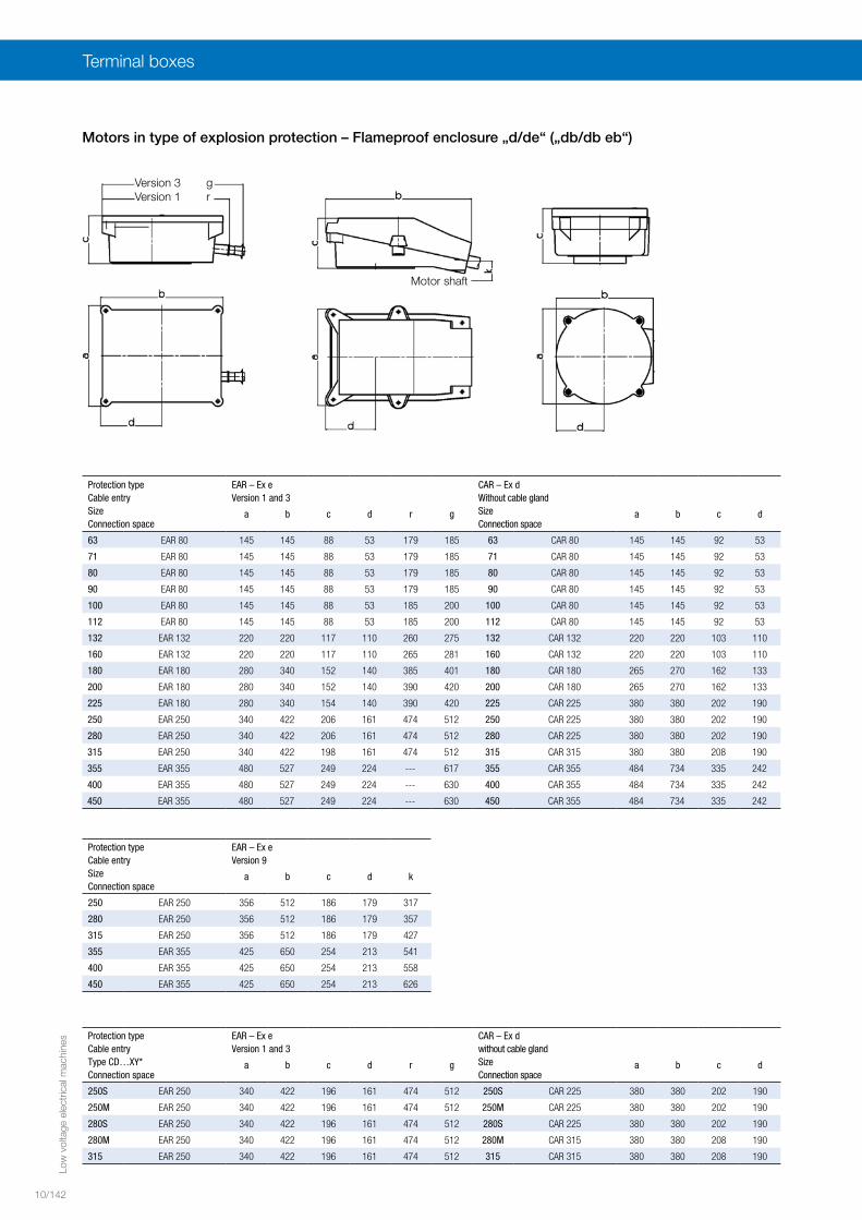
Thread 1 x M25 x 1.5 1 x M32 x 1.5 1 x M40 x 1.5 1 x M50 x 1.5 1 x M63 x 1.5 not available
for cableOuter diameter-Ø mm
13–19 12–21 17–28 21–35 27–48 not available
3
Thread 1 x M25 x 1.5 1 x M32 x 1.5 1 x M40 x 1.5 1 x M50 x 1.5 1 x M63 x 1.5 1 x M80 x 2 1 x M90 x 2
for cableOuter diameter-Ø mm
11–16 15–20 19–27 26–34 35–46 62–68 74–80
9 for cableOuter diameter-Ø mm
not available 1 x Ø 48–702 x Ø 26–48
1 x Ø 48–702 x Ø 48–70
Normal version
Terminal boxes in normal version Ex e („eb“) IIC
The terminal boxes of low-voltage motors are supplied withmetric threads, with assignments according to DIN 42 925and cable glands according to EN 50262, certified toEN 60079-7.
From size 180, they are provided with a detachable screw-ed plate to accommodate either threaded compressionglands or conductor glands. From size 250, longitudinallydivided terminal boxes are also available.
An additional terminal box for thermal monitoring or spaceheating can be supplied upon request for motors fromsize 132. The additional box is screwed onto the motorterminal box, except for sizes 355 to 450, where it ismounted on the housing.
Low
vol
tage
ele
ctric
al m
achi
nes
10
10/141
Suitable cross-sections for Ex e („eb“) IIC for low voltage
Size Rated cross-section max. [mm2]
Rated current max. [A]
Terminal type No. of terminals Terminal thread
36 – 112 4 25 U-clamp terminal2) 6 M5
132, 160 10 63 U-clamp terminal2) 6 M6
180 – 225 70 100 Tab terminal2) 6 M8
250 – 280 120 250 Tab terminal2) 6 M12
315 150 3151) Round terminal2) 6 M12
355 – 450 300 4001) Round terminal2) 6 M16
355 – 450 400 6301) Universal terminal3) 6 M16
1) Material Cu2) Suitable for connection with and without cable lug3) Suitable for connection with cable lug
Terminal boxes for Ex d („db“) IIC for low voltage
The terminal boxes comply with the stipulations for explo-sion protection type Ex “d” (“db”) according to EN 60079.
In the normal version, they are provided with a threadedhole according to ISO DIN 13.Upon request, they can also be supplied with the threadversion specified in the bottom table. The required threaddimensions must be specified in the order.
Note: Cable entry components for explosion protectiontype Ex “d” (“db”) IIC must also comply with EN 60079-1and must be certified accordingly. These components arenot included in the scope of delivery.
Cable entry threads for Ex d („db“) terminal boxes for low-voltage motors
1) Type of construction IM V5 with protective canopy.2) For type 250 to 400-4, 6, 8: Specifications for 2 poles apply for dimensions DA, EA, GC, FA, DC.For type 450-6, 8: Specifications for 4 poles apply for dimensions EA, GC, FA, DC.
Lifting eye bolts from size 90.Dimension AC measured over screw head.Dimension HD refers to terminal box Ex “e”.Terminal box can be rotated by 4 x 90°.
DimensionsThree-phase motors with squirrel-cage rotor for operation in Zone 1 according to EN 60079-1Type of explosion protection – Flameproof enclosure „d/de“ („db/db eb“), High- and Premium Efficiency IE2, IE3
with surface cooling with radial fan, type of cooling IC 411
Type of construction IM B3, IM B6, IM B7, IM B8, IM V51), IM V6
Low
vol
tage
ele
ctric
al m
achi
nes
10
10/145
Type LC Shaft endPole number LD O D, DA E, EA GA, GC F, FA DB, DC
(IE-)K82R… 2 4 6, 8
80 M 417 417 - 127 2 x M25 x 1.5 19j6 40 21.5 6 M690 S 479 479 479 139 2 x M25 x 1.5 24j6 50 27 8 M890 L 479 479 479 139 2 x M25 x 1.5 24j6 50 27 8 M8100 L 515 515 515 154 2 x M32 x 1.5 28j6 60 31 8 M10112 M 608 608 608 189 2 x M32 x 1.5 28j6 60 31 8 M10132 S 645 645 645 226 2 x M32 x 1.5 38k6 80 41 10 M12132 S1 645 - - 226 2 x M32 x 1.5 38k6 80 41 10 M12132 S2 652 - - 226 2 x M32 x 1.5 38k6 80 41 10 M12132 M - 652 645* 226 2 x M32 x 1.5 38k6 80 41 10 M12132 M1 - - 645** 226 2 x M32 x 1.5 38k6 80 41 10 M12132 M2 - - 652** 226 2 x M32 x 1.5 38k6 80 41 10 M12
K82R Y2,Y3,Y
160 M 864 864 864 261 2 x M40 x 1.5 42k6 110 45 12 M16160 LY2 864 864 864** 261 2 x M40 x 1.5 42k6 110 45 12 M16160 LY3/Y 864 899 *** 261 2 x M40 x 1.5 42k6 110 45 12 M16180 M 909 909 - 369 2 x M40 x 1.5 48k6 110 51.5 14 M16180 LY2 - 909 909** 369 2 x M40 x 1.5 48k6 110 51.5 14 M16180 LY3/Y - 959 909 369 2 x M40 x 1.5 48k6 110 51.5 14 M16200 L 983 983 983 390 2 x M50 x 1.5 55m6 110 59 16 M20
Type LC LD Shaft endK82R… Pole number Pole number O D m6, DA m6 2) E, EA 2) GA, GC 2) F, FA 2) DB, DC 2)
225 S - 1175 1175 - 377 2 x M50 x 1.5 - 60 60 - 140 - 64 64 - 18 - M20225 M 1145 1175 1175 347 377 2 x M50 x 1.5 55 60 60 110 140 59 64 64 16 18 M20 M20250 M 1250 1250 1250 482 482 2 x M63 x 1.5 60 65 65 140 140 64 69 69 18 18 M20 M20280 S 1375 1375 1375 483 483 2 x M63 x 1.5 65 75 75 140 140 69 79.5 79.5 18 20 M20 M20280 M 1375 1375 1375 483 483 2 x M63 x 1.5 65 75 75 140 140 69 79.5 79.5 18 20 M20 M20315 S 1543 1573 1573 496 526 2 x M63 x 1.5 65 80 80 140 170 69 85 85 18 22 M20 M20315 M 1543 1573 1573 496 526 2 x M63 x 1.5 65 80 80 140 170 69 85 85 18 22 M20 M20315 L1 1543 1573 1573 496 526 2 x M63 x 1.5 65 80 80 140 170 69 85 85 18 22 M20 M20315 L2 1743 1773 1773 496 526 2 x M63 x 1.5 65 80 80 140 170 69 85 85 18 22 M20 M20315 L3 1743 1773 1773 496 526 2 x M63 x 1.5 65 80 80 140 170 69 85 85 18 22 M20 M20355 M - - 1980 - 702 2 x M80 x 2 75 90 90 140 170 79.5 95 95 20 25 M20 M24
Type LC LD Shaft endCD… Pole number Pole number O D m6, DA m6 2) E, EA 2) GA, GC 2) F, FA 2) DB, DCXY2/XY3 2 4 6, 8 2 4, 6, 8 2 4 6, 8 2 4, 6, 8 2 4 6, 8 2 4, 6, 8 2 4, 6, 8
250 S 1250 1250 1250 482 482 2 x M63 x 1.5 60 65 65 140 140 64 69 69 18 18 M20 M20250 M 1375 1375 1375 483 483 2 x M63 x 1.5 60 65 65 140 140 64 69 69 18 18 M20 M20280 S 1375 1375 1375 483 483 2 x M63 x 1.5 65 75 75 140 140 69 79.5 79.5 18 20 M20 M20280 M 1543 1573 1573 496 526 2 x M63 x 1.5 65 75 75 140 140 69 79.5 79.5 18 20 M20 M20315 S 1543 1573 1573 496 526 2 x M63 x 1.5 65 80 80 140 170 69 85 85 18 22 M20 M20315 M 1543 1573 1573 496 526 2 x M63 x 1.5 65 80 80 140 170 69 85 85 18 22 M20 M20315 L1 1743 1773 1773 496 526 2 x M63 x 1.5 65 80 80 140 170 69 85 85 18 22 M20 M20315 L2 1743 1773 1773 496 526 2 x M63 x 1.5 65 80 80 140 170 69 85 85 18 22 M20 M20
For pole-switching motors (4/2, 6/4 and 8/4), the 4-pole shaft end is used.Exception: Motors in sizes 355, 400 and 450 with pole-switching configuration 4/2. In this case, the 2-pole shaft end is used.The length dimension L corresponds to 4-pole motors for all sizes.
Internal threadto DIN 332-DØ DB
Internal threadto DIN 332-DØ DC
Low
vol
tage
ele
ctric
al m
achi
nes
10/146
Dimensions
Three-phase motors with squirrel-cage rotor for operation in Zone 1 according to EN 60079-1Type of explosion protection – Flameproof enclosure „d/de“ („db/db eb“), High- and Premium Efficiency IE2, IE3
with surface cooling with radial fan, type of cooling IC 411
Type of construction IM B5, IM V11), IM V3
Mounting flange L LCType LA M N P S H17 T AC AD Pole number Pole numberIE.-K82R… 2 4 6 8 2 4 6 8
¹) Type of construction IM V5 with protective canopy2) For type 250 to 315-4, 6, 8: Specifications for 2 poles apply for dimensions DA, EA, GC, FA, DC.
Low
vol
tage
ele
ctric
al m
achi
nes
10
10/147
Type LE Shaft endLD Pole number O D, DA E, EA GA, GC F, FA DB, DC
IE.-K82R… 2 4 6, 8
80 M 127 25 25 25 2 x M25 x 1.5 19 j6 40 21.5 6 M690 S+L 139 25 25 25 2 x M25 x 1.5 24 j6 50 27 8 M8100 L 154 30 30 30 2 x M32 x 1.5 28 j6 60 31 8 M10112 M 189 30 30 30 2 x M32 x 1.5 28 j6 60 31 8 M10132 S+M 226 30 30 30 2 x M32 x 1.5 38 k6 80 41 10 M12
K82R…Y2/Y3/Y
160 M+L 261 66 66 66 2 x M40 x 1.5 42 k6 110 45 12 M16180 M+L 369 66 66 - 2 x M40 x 1.5 48 k6 110 51.5 14 M16200 L 390 77 77 77 2 x M50 x 1.5 55 m6 110 59 16 M20
225 S - 377 - 87 87 2 x M50 x 1.5 - 60 60 - 140 - 64 64 - 18 - M20225 M 347 377 87 87 87 2 x M50 x 1.5 55 60 60 110 140 59 64 64 16 18 M20 M20250 M 482 482 94 94 94 2 x M63 x 1.5 60 65 65 140 140 64 69 69 18 18 M20 M20280 S 483 483 110 110 110 2 x M63 x 1.5 65 75 75 140 140 69 79.5 79.5 18 20 M20 M20280 M 483 483 110 110 110 2 x M63 x 1.5 65 75 75 140 140 69 79.5 79.5 18 20 M20 M20315 S 496 526 115 115 115 2 x M63 x 1.5 65 80 80 140 170 69 85 85 18 22 M20 M20315 M 496 526 115 115 115 2 x M63 x 1.5 65 80 80 140 170 69 85 85 18 22 M20 M20315 L1 496 526 115 115 115 2 x M63 x 1.5 65 80 80 140 170 69 85 85 18 22 M20 M20315 L2 496 526 115 115 115 2 x M63 x 1.5 65 80 80 140 170 69 85 85 18 22 M20 M20315 L3 496 526 115 115 115 2 x M63 x 1.5 65 80 80 140 170 69 85 85 18 22 M20 M20355 M - 702 130 130 130 2 x M80 x 2 75 90 90 140 170 79.5 95 95 20 25 M20 M24
K82R … XY2/XY3/XY
250 S 482 482 94 94 94 2 x M63 x 1.5 60 65 65 140 140 64 69 69 18 18 M20 M20250 M 483 483 110 110 110 2 x M63 x 1.5 60 65 65 140 140 64 69 69 18 18 M20 M20280 S 483 483 110 110 110 2 x M63 x 1.5 65 75 75 140 140 69 79.5 79.5 18 20 M20 M20280 M 496 526 115 115 115 2 x M63 x 1.5 65 75 75 140 140 69 79.5 79.5 18 20 M20 M20315 S 496 526 115 115 115 2 x M63 x 1.5 65 80 80 140 170 69 85 85 18 22 M20 M20315 M 496 526 115 115 115 2 x M63 x 1.5 65 80 80 140 170 69 85 85 18 22 M20 M20315 L1 496 526 115 115 115 2 x M63 x 1.5 65 80 80 140 170 69 85 85 18 22 M20 M20315 L2 496 526 115 115 115 2 x M63 x 1.5 65 80 80 140 170 69 85 85 18 22 M20 M20
For pole-switching motors (4/2, 6/4 and 8/4), the 4-pole shaft end is used.Exception: Motors in sizes 355, 400 and 450 with pole-switching configuration 4/2.In this case, the 2-pole shaft end is used. The length dimension L corresponds to 4-pole motors for all sizes.
Internal threadto DIN 332-DØ DB
Internal threadto DIN 332-DØ DC
Type of construction IM V1 only
Positions of flange holesSize 63 to 200
Positions of flange holesSize 225 to 450
Low
vol
tage
ele
ctric
al m
achi
nes
10/148
Dimensions
Three-phase motors with squirrel-cage rotor for operation in Zone 1 according to EN 60079-1Type of explosion protection – Flameproof enclosure „d/de“ („db/db eb“), High- and Premium Efficiency IE2, IE3
with surface cooling with radial fan, type of cooling IC 411
Mounting flange according to EN 50347, form FT.Lifting eye bolts from size 90.Dimension AC measured over screw head.Dimension HD refers to terminal space Ex “e”.Terminal space can be rotated by 4 x 90°.
¹) Protective canopy required for type of construction IM V17 and IM V182) For pole-switching motors (4/2, 6/4 and 8/4), the 4-pole shaft end is used.Exception: Motors in sizes 355, 400 and 450 with pole-switching configuration 4/2.In this case, the 2-pole shaft end is used. The length dimension L corresponds to 4-polemotors for all sizes.
Internal threadto DIN 332-DØ DB
Internal threadto DIN 332-DØ DC
Type of construction IM V17, IM V18 only
Type of construction IM B14, IM V18, IM V19 without feet
Low
vol
tage
ele
ctric
al m
achi
nes
10
10/149
Low
vol
tage
ele
ctric
al m
achi
nes
10/150
Dimensions
Type A AA AB AC B BA BB BC C H -0.5 HA HD K H17 K’ H17 LPole number
Three-phase motors with squirrel-cage rotor for operation in Zone 1 according to EN 60079-1Type of explosion protection – Flameproof enclosure „d/de“ („db/db eb“), Standard Efficiency IE1
with surface cooling with radial fan, type of cooling IC 411
Type of construction IM B3, IM B6, IM B7, IM B8, IM V51), IM V6
Size 63 in T4 non-ventilated.Lifting eye bolts from size 90Dimension AC measured over screw head.Dimension HD for Ex “e”, rotatable.Applies also for series BD ...
¹) Type of construction IM V5 with protective canopy.2) For type 250 to 400-4, 6, 8: Specifications for 2 poles apply for dimensions DA, EA, GC, FA, DC.
For type 450-6, 8: Specifications for 4 poles apply for dimensions EA, GC, FA, DC.
Internal threadto DIN 332-DØ DB
Internal threadto DIN 332-DØ DC
Low
vol
tage
ele
ctric
al m
achi
nes
10
10/151
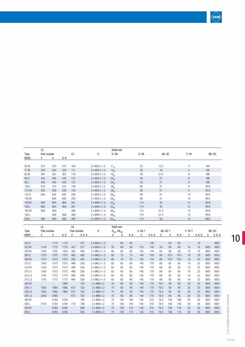
LC Shaft endType Pole number LD O D, DA E, EA GA, GC F, FA DB, DCK82R… 2 4 6, 8
63 M 274 274 274 104 2 x M25 x 1.5 11j6 23 12.5 4 M471 M 334 334 334 111 2 x M25 x 1.5 14j6 30 16 5 M580 M 387 387 387 116 2 x M25 x 1.5 19j6 40 21.5 6 M690 S 445 445 445 137 2 x M25 x 1.5 24j6 50 27 8 M890 L 445 445 445 137 2 x M25 x 1.5 24j6 50 27 8 M8100 L 510 510 510 149 2 x M32 x 1.5 28j6 60 31 8 M10112 M 526 526 526 154 2 x M32 x 1.5 28j6 60 31 8 M10132 S 645 645 645 226 2 x M32 x 1.5 38k6 80 41 10 M12132 M - 645 645 226 2 x M32 x 1.5 38k6 80 41 10 M12160 M 864 864 864 261 2 x M40 x 1.5 42k6 110 45 12 M16160 L 864 864 864 261 2 x M40 x 1.5 42k6 110 45 12 M16180 M 909 909 - 369 2 x M40 x 1.5 48k6 110 51.5 14 M16180 L - 909 909 369 2 x M40 x 1.5 48k6 110 51.5 14 M16200 L 983 983 983 390 2 x M50 x 1.5 55m6 110 59 16 M20
LC LD Shaft endType Pole number Pole number O Dm6. DAm6 E. EA 2) GA. GC 2) F. FA 2) DB. DCK82R… 2 4 6. 8 2 4. 6. 8 2 4 6. 8 2 4. 6. 8 2 4 6. 8 2 4. 6. 8 2 4. 6. 8
225 S - 1175 1175 - 377 2 x M50 x 1.5 - 60 60 - 140 - 64 64 - 18 - M20225 M 1145 1175 1175 347 377 2 x M50 x 1.5 55 60 60 110 140 59 64 64 16 18 M20 M20250 M 1250 1250 1250 482 482 2 x M63 x 1.5 60 65 65 140 140 64 69 69 18 18 M20 M20280 S 1375 1375 1375 483 483 2 x M63 x 1.5 65 75 75 140 140 69 79.5 79.5 18 20 M20 M20280 M 1375 1375 1375 483 483 2 x M63 x 1.5 65 75 75 140 140 69 79.5 79.5 18 20 M20 M20315 S 1543 1573 1573 496 526 2 x M63 x 1.5 65 80 80 140 170 69 85 85 18 22 M20 M20315 M 1543 1573 1573 496 526 2 x M63 x 1.5 65 80 80 140 170 69 85 85 18 22 M20 M20315 L1 1543 1573 1573 496 526 2 x M63 x 1.5 65 80 80 140 170 69 85 85 18 22 M20 M20315 L2 1743 1773 1773 496 526 2 x M63 x 1.5 65 80 80 140 170 69 85 85 18 22 M20 M20315 L3 1743 1773 1773 496 526 2 x M63 x 1.5 65 80 80 140 170 69 85 85 18 22 M20 M20355 M - - 1980 - 702 2 x M80 x 2 75 90 90 140 170 79.5 95 95 20 25 M20 M24355 L1 1925 1980 1980 672 702 2 x M80 x 2 75 90 90 140 170 79.5 95 95 20 25 M20 M24355 L2 1950 1980 1980 672 702 2 x M80 x 2 75 90 90 140 170 79.5 95 95 20 25 M20 M24355 L3 2030 2060 - 672 702 2 x M80 x 2 75 90 90 140 170 79.5 95 95 20 25 M20 M24400 M - 2190 2190 - 788 2 x M95 x 2 75 100 100 140 210 79.5 106 106 20 28 M20 M24400 L 2120 2190 2190 718 788 2 x M95 x 2 75 100 100 140 210 79.5 106 106 20 28 M20 M24450 M - 2280 2280 - 826 2 x M95 x 2 75 100 110 140 210 79.5 106 116 20 28 M20 M24450 L - 2280 2280 - 826 2 x M95 x 2 75 100 110 140 210 79.5 106 116 20 28 M20 M24
Low
vol
tage
ele
ctric
al m
achi
nes
10/152
Dimensions
Three-phase motors with squirrel-cage rotor for operation in Zone 1 according to EN 60079-1Type of explosion protection – Flameproof enclosure „d/de“ („db/db eb“), Standard Efficiency IE1
with surface cooling with radial fan, type of cooling IC 411
Type of construction IM B5, IM V11), IM V3
Size 63 in T4 non-ventilated.Mounting flange according to EN 50347, form FF.Lifting eye bolts from size 90Dimension AC measured over screw head.Dimension HD refers to terminal space Ex “e”.Terminal space can be rotated by 4 x 90°.
Mounting flange L LCType LA M N P S H17 T AC AD Pole number Pole numberK82R… 2 4 6 8 2 4 6 8
Applies also for series BD ...Size 400 to 450 only available in type of construction V1.
¹) Type of construction IM V5 with protective canopy.2) For type 250 to 400-4, 6, 8: Specifications for 2 poles apply for dimensions DA, EA, GC, FA, DC.
For type 450-6, 8: Specifications for 4 poles apply for dimensions EA, GC, FA, DC.
Internal threadto DIN 332-DØ DB
Internal threadto DIN 332-DØ DC
Type of construction IM V1 only
Positions of flange holesSize 63 to 200
Positions of flange holesSize 225 to 450
Low
vol
tage
ele
ctric
al m
achi
nes
10
10/153
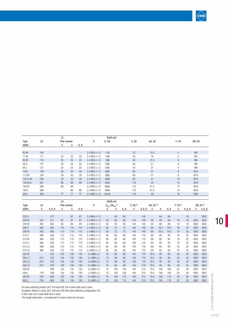
LE Shaft endType LD Pole number O D, DA E, EA GA, GC F, FA DB, DCK82R… 2 4 6, 8
63 M 104 - - - 2 x M25 x 1.5 11j6 23 12.5 4 M471 M 111 25 25 25 2 x M25 x 1.5 14j6 30 16 5 M580 M 116 25 25 25 2 x M25 x 1.5 19j6 40 21.5 6 M690 S 137 25 25 25 2 x M25 x 1.5 24j6 50 27 8 M890 L 137 25 25 25 2 x M25 x 1.5 24j6 50 27 8 M8100 L 149 30 30 30 2 x M32 x 1.5 28j6 60 31 8 M10112 M 154 30 30 30 2 x M32 x 1.5 28j6 60 31 8 M10132 S+M 226 30 30 30 2 x M32 x 1.5 38k6 80 41 10 M12160 M+L 261 66 66 66 2 x M40 x 1.5 42k6 110 45 12 M16180 M 369 66 66 - 2 x M40 x 1.5 48k6 110 51.5 14 M16180 L 369 - 66 66 2 x M40 x 1.5 48k6 110 51.5 14 M16200 L 390 77 77 77 2 x M50 x 1.5 55m6 110 59 16 M20
225 S - 377 - 87 87 2 x M50 x 1.5 - 60 60 - 140 - 64 64 - 18 - M20225 M 347 377 87 87 87 2 x M50 x 1.5 55 60 60 110 140 59 64 64 16 18 M20 M20250 M 482 482 94 94 94 2 x M63 x 1.5 60 65 65 140 140 64 69 69 18 18 M20 M20280 S 483 483 110 110 110 2 x M63 x 1.5 65 75 75 140 140 69 79.5 79.5 18 20 M20 M20280 M 483 483 110 110 110 2 x M63 x 1.5 65 75 75 140 140 69 79.5 79.5 18 20 M20 M20315 S 496 526 115 115 115 2 x M63 x 1.5 65 80 80 140 170 69 85 85 18 22 M20 M20315 M 496 526 115 115 115 2 x M63 x 1.5 65 80 80 140 170 69 85 85 18 22 M20 M20315 L1 496 526 115 115 115 2 x M63 x 1.5 65 80 80 140 170 69 85 85 18 22 M20 M20315 L2 496 526 115 115 115 2 x M63 x 1.5 65 80 80 140 170 69 85 85 18 22 M20 M20315 L3 496 526 115 115 115 2 x M63 x 1.5 65 80 80 140 170 69 85 85 18 22 M20 M20355 M - 702 130 130 130 2 x M80 x 2 75 90 90 140 170 79.5 95 95 20 25 M20 M24355 L1 672 702 130 130 130 2 x M80 x 2 75 90 90 140 170 79.5 95 95 20 25 M20 M24355 L2 672 702 130 130 130 2 x M80 x 2 75 90 90 140 170 79.5 95 95 20 25 M20 M24355 L3 672 702 130 130 130 2 x M80 x 2 75 90 90 140 170 79.5 95 95 20 25 M20 M24400 M - 788 130 130 130 2 x M95 x 2 75 100 100 140 210 79.5 106 106 20 28 M20 M24400 L 718 788 130 130 130 2 x M95 x 2 75 100 100 140 210 79.5 106 106 20 28 M20 M24450 M 704 826 130 130 130 2 x M95 x 2 75 100 110 140 210 79.5 106 116 20 28 M20 M24450 L 704 826 130 130 130 2 x M95 x 2 75 100 110 140 210 79.5 106 116 20 28 M20 M24
For pole-switching motors (4/2, 6/4 and 8/4), the 4-pole shaft end is used.Exception: Motors in sizes 355, 400 and 450 with pole-switching configuration 4/2.In this case, the 2-pole shaft end is used.The length dimension L corresponds to 4-pole motors for all sizes.
Low
vol
tage
ele
ctric
al m
achi
nes
10/154
Dimensions
Three-phase motors with squirrel-cage rotor for operation in Zone 1 according to EN 60079-1Type of explosion protection – Flameproof enclosure „d/de“ („db/db eb“), Standard Efficiency IE1
with surface cooling with radial fan, type of cooling IC 411
Type of construction IM B14, IM B34; IM V171), IM V181), IM V19, IM V37
Mounting flangeType LA M N j6 P S TK82R…
63 M 8 75 60 90 M5 2.571 M 8 85 70 105 M6 2.580 M 10 100 80 120 M6 390 S+L 10 115 95 140 M8 3100 L 12 130 110 160 M8 3.5112 M 12 130 110 160 M8 3.5132 S+M 12 165 130 200 M10 3.5
Size 63 in T4 non-ventilated.Mounting flange according to EN 50347, form FT.Lifting eye bolts from size 90Dimension AC measured over screw head.Dimension HD refers to terminal space Ex “e”.Terminal space can be rotated by 4 x 90°.Applies also for series BD ...
¹) Protective canopy required for type of construction IM V17 and IM V182) For pole-switching motors (4/2, 6/4 and 8/4), the 4-pole shaft end is used.Exception: Motors in sizes 355, 400 and 450 with pole-switching configuration 4/2.In this case, the 2-pole shaft end is used. The length dimension L corresponds to 4-polemotors for all sizes.