42
Exposure Controls for physical Agents
| Date post: | 10-Nov-2018 |
| Category: |
Documents |
| Upload: | nguyenkien |
| View: | 213 times |
| Download: | 0 times |

Exposure Controls for physical Agents

Nature of physical agents • Physical agents usually involve the transfer
of energy from a source to a human receptor • The energy can be in various forms:
– Mechanical: noise, vibration, ultrasound – Electrical: electric shock – Electromagnetic
• NIR: UV & , visible light, Infrared/heat, RF/microwaves • Ionizing: X-rays, γ radiation,
– Energetic particles: α, β, neutrons, protons
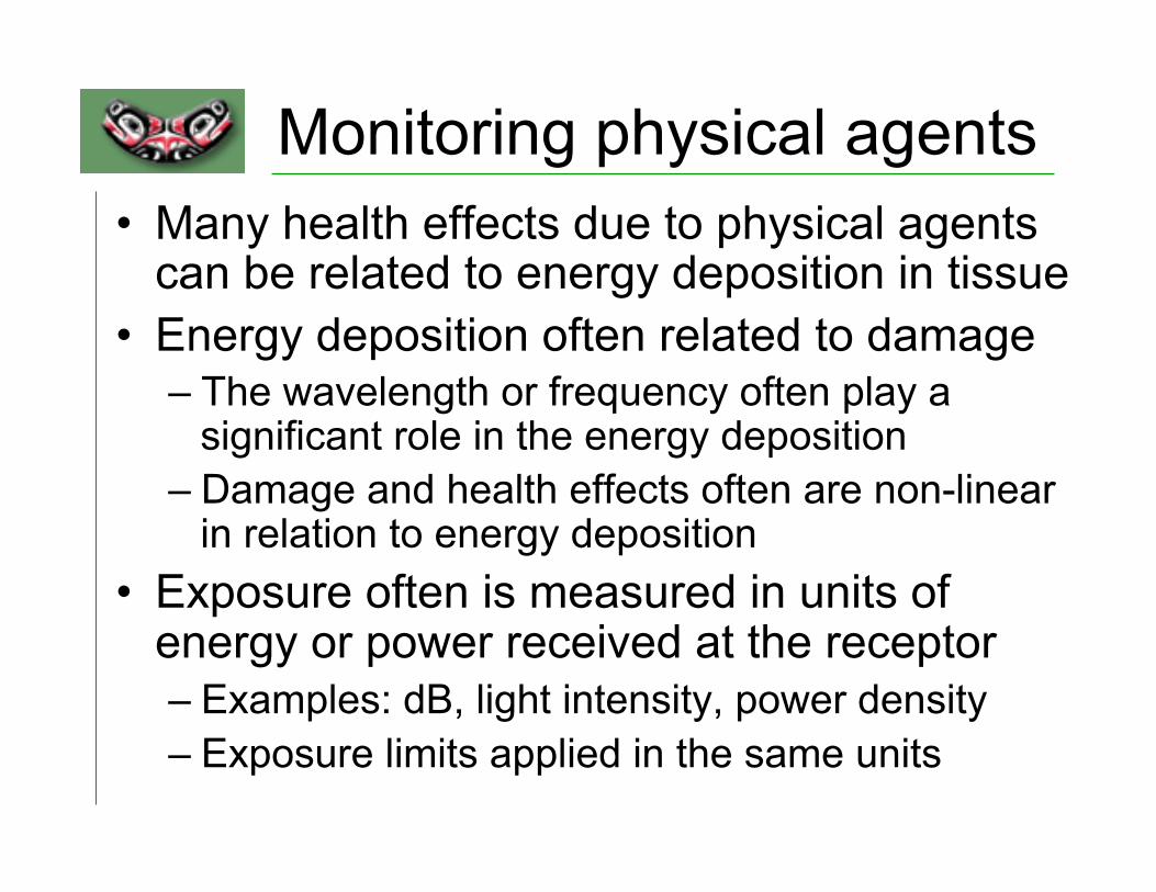
Monitoring physical agents • Many health effects due to physical agents
can be related to energy deposition in tissue • Energy deposition often related to damage
– The wavelength or frequency often play a significant role in the energy deposition
– Damage and health effects often are non-linear in relation to energy deposition
• Exposure often is measured in units of energy or power received at the receptor – Examples: dB, light intensity, power density – Exposure limits applied in the same units

Physical Agents: Control strategies
• Control strategies for physical agents generally follow those for other chemicals – Control at source, pathway, or receptor
• For physical agents we want to limit the transfer of energy (or power) to the receptor – Limit the power emitted by the source – Lower the power transmitted over the pathway – Reduce the power absorbed at the source

4 basic interactions: transmission, absorption, reflection, scattering
Absorption causes heating or other effects due to energy deposition
Energy transfer depends on wavelength, polarization and geometry
Energy transfer

Example: Noise Control • AT THE SOURCE: • Acoustical design
– Decouple energy from vibrating system
– Change coupling between energy and acoustical radiating system
– Change structure so less sound is radiated
• Substitute less noisy equip. • Change processing
methods
• CHANGES IN PATH: – Increase source-receiver
distance – Acoustical treatment of
ceiling, walls & floor (reverberation)
– Enclose noise source
• AT RECEIVER BY – Personal Protection – Enclosure for worker – Job rotation schedule – Work hours

NOISE CONTROL AND REDUCTION • Control points at:
– Plant design – At the source – Along the path – At the Receiver

CONTROL AT THE SOURCE
• SUBSTITUTE for quieter equipment, processes or materials
• REDUCE DRIVING FORCE by reducing motion, maintaining dynamic balance, increasing duration of work cycle, and providing vibration isolation
• REDUCE RESPONSE of vibrating surfaces by dampening and decreasing radiating area
• REDUCE VELOCITY flow of fluids
NOISE REDUCTION ALONG SOUND PATH • Move position of the person or noise source • Change acoustics of the environment Room
absorption • Provide barriers between noise source and
receiver • Enclosures • Mufflers • Sound shields
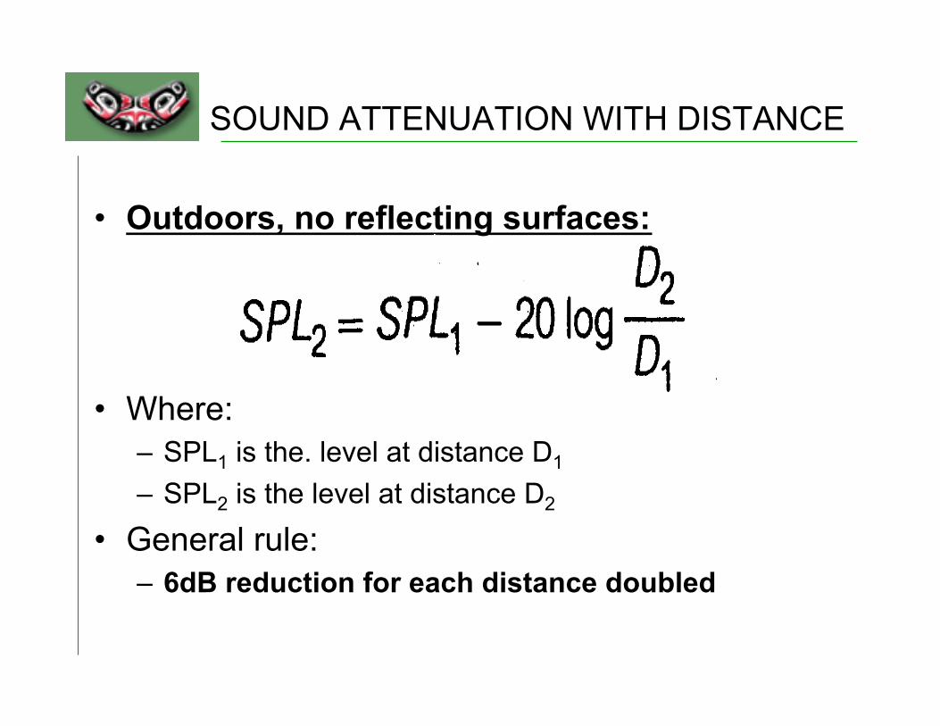
SOUND ATTENUATION WITH DISTANCE
• Outdoors, no reflecting surfaces:
• Where: – SPL1 is the. level at distance D1 – SPL2 is the level at distance D2
• General rule: – 6dB reduction for each distance doubled

Enclosure Design Guidelines • Air tight enclosure works best • Acoustical absorption added to the interior of the
enclosure is essential for effectiveness • Enclosures are improved by using heavier walls • A single leak can destroy the enclosure
effectiveness • Use of porous materials are of little value • Acoustical absorbing materials on the outside of
an enclosure does not improve the effectiveness • Vibrations transmitted from the source to the
enclosure can destroy enclosure effectiveness

Absorption Coefficient (α)
• Where • Ei = the incident energy • Er = the reflected energy • Ea = the absorbed energy • ABSORBANCE (A) = αS
– Note: Absorbance is measured in sabins where 1 sabin = 1 sq ft of perfect absorbance

Sound absorption coefficients of common acoustic materials
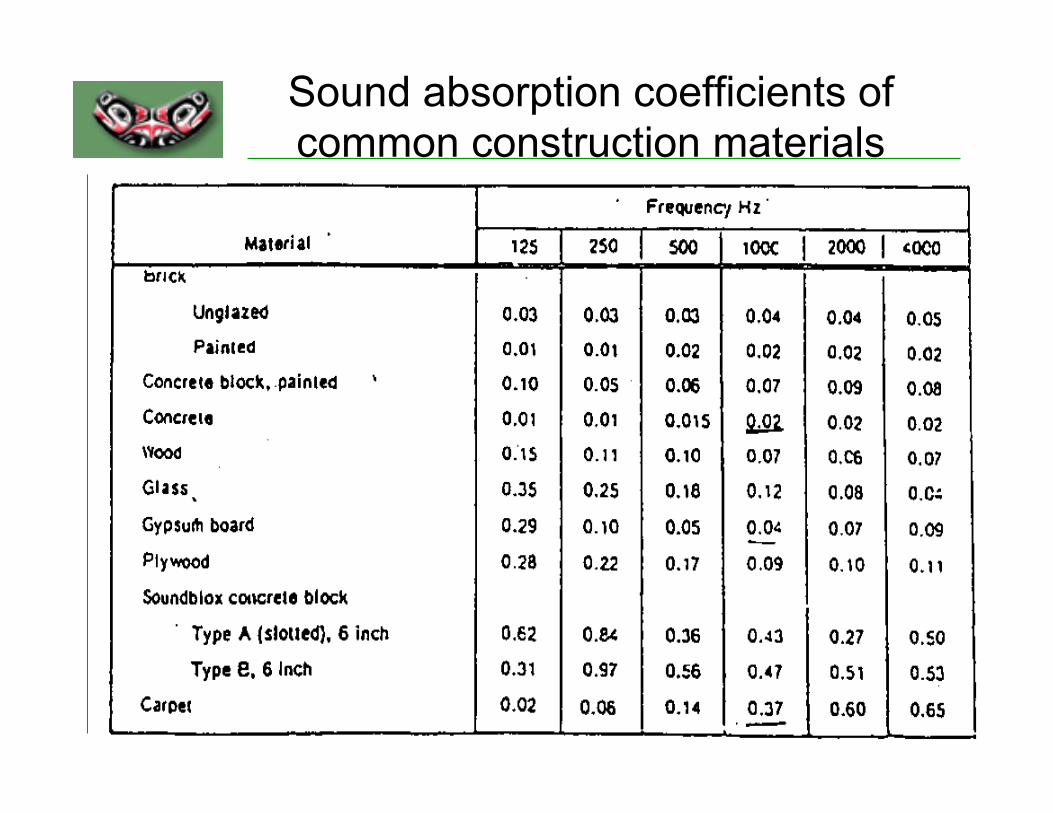
Sound absorption coefficients of common construction materials

Noise Reduction by Absorption
• NR = 10 log A2/A1
• Where: – NR is the noise reduction (dB) – A1 is the initial absorption sabins, – A2 is the final absorption (sabins)

Calculating room absorption • A room = Total number of absorption units in the room (Sabins)
• A room = Aceiling + A wall + Amachinery + Afloor • • A room = Sceiling αceiling + Swall αwall + Smachinery αmachinery + Sfloor αfloor
• 1. Calculate areas of ceilings walls, floor, other large surface area machinery separately
• 2. Determine appropriate absorption coefficient for each type of surface • 3. Multiply the area and absorption coefficient for each type of surface and
sum the total of these products to determine A room • 4. Calculate A room before treatment using absorption coefficients of the old
materials • 5. Calculate A room after treatment using absorption coefficients of the new
materials • 6. Calculate NR = 10 1og(A room , after treatment ) / (A room , after treatment ) • 7. Calculations must be completed for all octave band center frequencies

Absorption in relation to R

Room Constant (R)
Note: R is the measure for how “live” a room or an enclosure is.
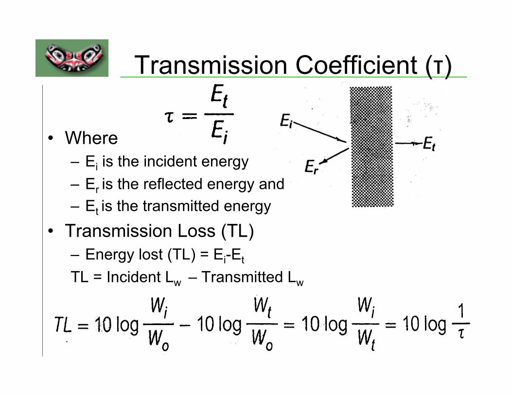
Transmission Coefficient (τ)
• Where – Ei is the incident energy – Er is the reflected energy and – Et is the transmitted energy
• Transmission Loss (TL) – Energy lost (TL) = Ei-Et TL = Incident Lw – Transmitted Lw

Transmission loss of common materials

Transmission loss from enclosures • Transmission Loss (TL)
– The amount of energy lost (in dB) as sound travels through an enclosure
• Determining required transmission loss – 1) Determine the amount of attenuation needed – 2) Allow for reverberant buildup or provide enclosure
treatment with an absorption coefficient of >0.7 – 3) For each frequency, subtract the TL from the SPL – 4) Add the resultant sound pressure levels to determine
total transmission loss

Hearing Protectors • Sound pathways through protectors
– 1. Air leaks – 2. Hearing protector vibration – 3. Material Transmission – 4. Bone/tissue conduction
Inserts Muffs
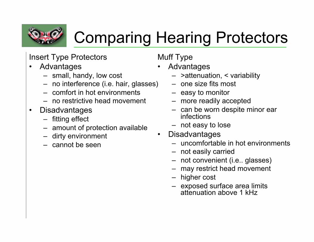
Comparing Hearing Protectors Insert Type Protectors • Advantages
– small, handy, low cost – no interference (i.e. hair, glasses) – comfort in hot environments – no restrictive head movement
• Disadvantages – fitting effect – amount of protection available – dirty environment – cannot be seen
Muff Type • Advantages
– >attenuation, < variability – one size fits most – easy to monitor – more readily accepted – can be worn despite minor ear
infections – not easy to lose
• Disadvantages – uncomfortable in hot environments – not easily carried – not convenient (i.e.. glasses) – may restrict head movement – higher cost – exposed surface area limits
attenuation above 1 kHz

Noise Reduction Rating (NRR) Hearing Protector Attenuation • Method #1
– 1) Obtain employee’s C-weighted TWA – 2) Subtract NRR to determine estimated A-weighted
TWA under the ear protector • Method #2
– 1) Obtain employee’s A-weighted TWA – 2) Subtract 7 dB from the NRR – 3) Subtract remainder from the A-weighted TWA to
determine A-weighted TWA under the ear protector

END Noise Part
This image is copyrighted.
Lasers

Laser Hazard Classification


1. Eye : Acute exposure of the eye to lasers of certain wavelengths and power can cause corneal or retinal burns (or both). Chronic exposure to excessive levels may cause corneal or lenticular opacities (cataracts) or retinal injury. 2. Skin : Acute exposure to high levels of optical radiation may cause skin burns; while carcinogenesis may occur for ultraviolet wavelengths (290-320 nm). 3. Chemical : Some lasers require hazardous or toxic substances to operate (i.e., chemical dye, excimer lasers). 4. Electric shock : Most lasers produce high voltages that can be lethal. 5. Fire hazards : The solvents used in dye lasers are flammable. High voltage pulse or flash lamps may cause ignition. Flammable materials may be ignited by direct beams or specular reflections from high power continuous wave (CW) infrared lasers.
Types of laser hazards

“Reflected beam caused vision loss”
Description: Professor from China removed eyewear to "see better" while doing an experiment with a crystal. Exposure produced retinal burn and permanent vision loss. He described seeing a white flash, central purple spot surrounded by yellow halo. No pain reported.

“Retinal burn from rear laser mirror”
Description: Student WITH EYEWEAR ON (and witness to verify) received exposure from the rear mirror of a "Continuium" YAG laser. The student was wearing Glendale Broadband (OD 4.0) eyewear; ANSI standard requires OD=6.0. Retinal burn resulted with permanent damage. Type:Nd:YAG Divergence:- Wavelength:532 nm Energy/Power:0.18/0.40 Class:- Pulse Rate:5 KHz Exposure Time:7 ns

Example of eye injury
Experience has demonstrated that most laser injuries go unreported for 24–48 hours by the injured person. This is a
critical time for treatment of the injury.

Retinal Burn
A range of injuries induced with a Nd:YAG laser on a monkey retina. The white spots in the centre are thermal burns, i.e. coagulation of retinal layers. With larger energies, holes in the retina are produced which result either in bleeding into the vitreous (the gel-like substance which fills the centre of the eye ball), or the bleeding is contained in the layers of the retina, which results in functional loss in the affected area. Photograph courtesy of J. Zuclich, TASC Litton, TX, USA.

Eye Damage: Focusing
With safety rule Cornea Damage BAD
Retina Damage WORSE
• Your Eyes Are Designed to Focus
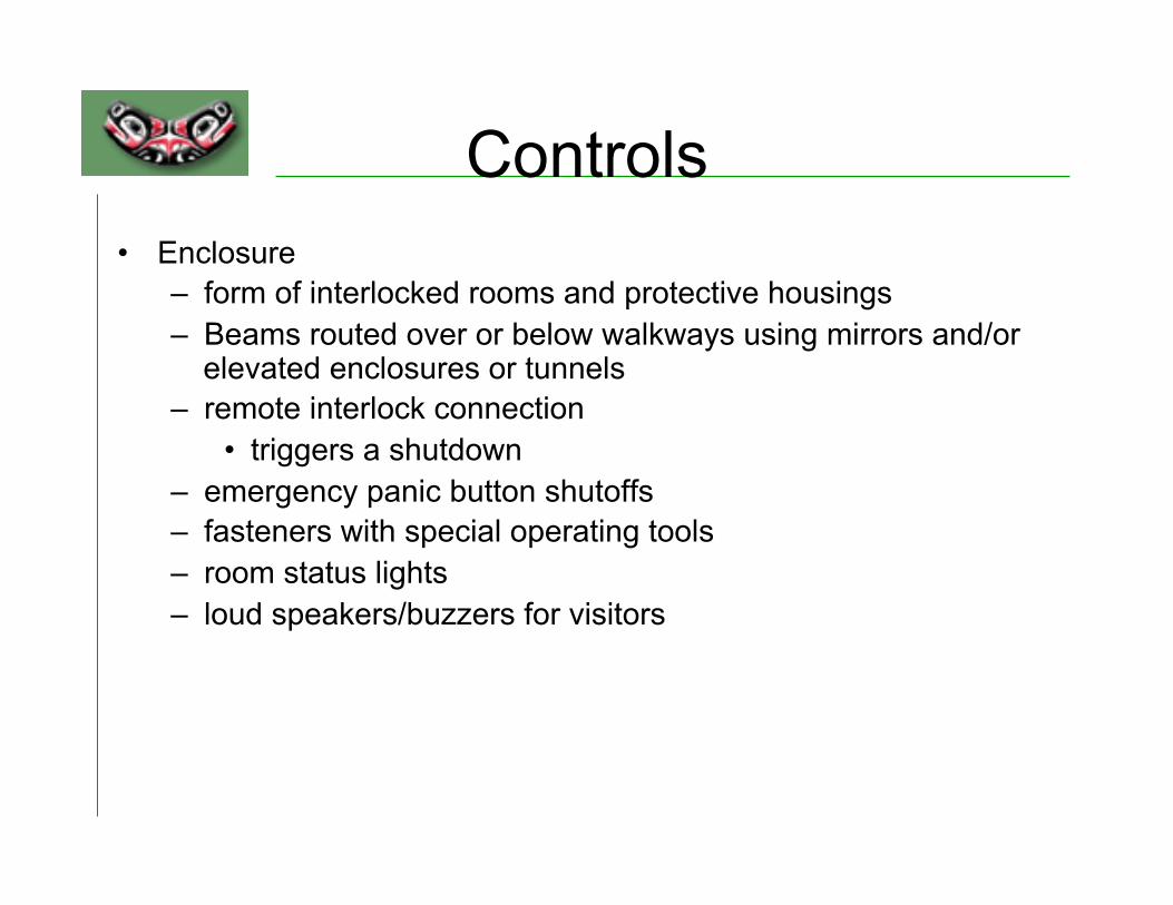
Controls • Enclosure
– form of interlocked rooms and protective housings – Beams routed over or below walkways using mirrors and/or
elevated enclosures or tunnels – remote interlock connection
• triggers a shutdown – emergency panic button shutoffs – fasteners with special operating tools – room status lights – loud speakers/buzzers for visitors

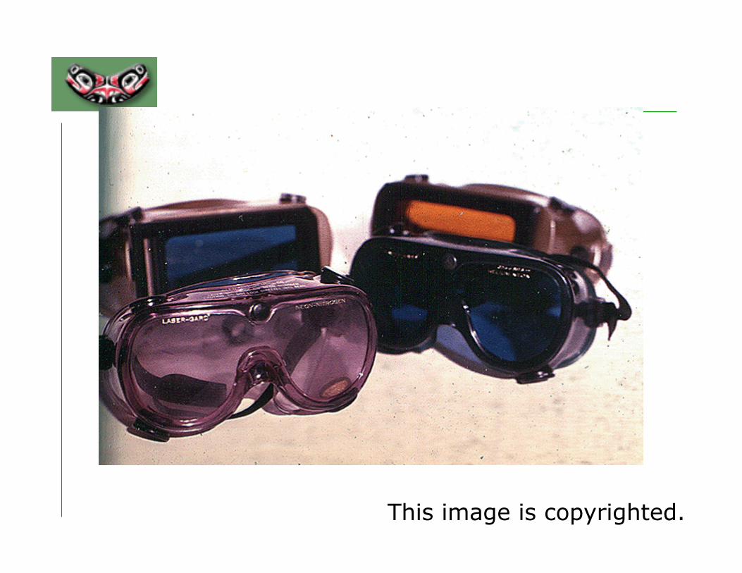
This image is copyrighted.


Exposure Limits – Retinal Injury Thresholds - I
- At 10-12 seconds the threshold for a retinal injury is ~ 10-7 J/cm2 (i.e. 105 W/cm2). - Because of the x 105 enhancement in the eye this value is elevated to 10-2
J/cm2 (i.e. 1010 W/cm2) on the retina. - These exposure levels are further enhanced by self-focusing.


