Expression of Interest – Direct Fixation Rail Fasteners The Washington Metropolitan Area Transit Authority (WMATA) is seeking feedback from suppliers, vendors and manufacturers to determine if a commercially available product can meet our needs. This inquiry is specific to rapid transit (75 mph speed, 17 ton vertical axle load, and 6,000 pound lateral load) direct fixation track wherein the running rail is secured via an insulated fastener to the structural deck or concrete surface. Currently, WMATA has in service fasteners that are secured to the structural deck via a two-bolt lag system. At times, this two bolt lag system does not perform as intended and WMATA seeks a more robust fastener that perhaps uses more lags to secure the fastener to the structural member which will deliver a more robust lateral load restraining system. In addition, many modern fasteners are made with “layers” of steel and rubber that are not connected throughout the transverse cross section which allows the top and bottom layers of the fastener to fail in a shearing mode. WMATA is not able to increase the width or height of the fastener assembly due to practical constraints of the existing system. WMATA also prefers an insulated lag to ensure that signal and traction power current is not able to travel from the running rail to ground via the fastener assembly. Also, WMATA prefers a fastener assembly that uses elastic clips to secure the rail to the fastener body as opposed to bolted connections. WMATA is not interested in pursuing a solution which entails structural concrete work, but rather a fastener assembly that can be attached to our existing tunnel and aerial structural members that delivers a greater resistance to lateral loads and stray current. WMATA’s specifications for direct fixation fasteners are attached. Interested offerors shall provide information regarding faster assembly as described above. In addition, interested offerors shall provide a capability statement of their experience in successfully providing similar solutions to other transit agencies or railroads. The capability statement shall include the name and address of the transit agency or railroad, a brief description of the equipment provided, and a contact person’s name and telephone number from the transit agency or railroad Please forward the above information along with your company’s name, address, point of contact, telephone number, and email address no later than December 23, 2016 to Fred Voellm, Contract Administrator, Washington Metropolitan Area Transit Authority, Office of Procurement and Materials, 600 5th Street NW, Room 301-G, Washington, DC 20001. For questions, please email [email protected] or call 202-962-2485. Information submitted will be reviewed by WMATA engineering staff. WMATA may meet with individual offerors to discuss and review the information provided. If WMATA decides to proceed with procurement of the services or products offered, a formal solicitation will be issued.
Transcript
Expression of Interest – Direct Fixation Rail Fasteners The Washington Metropolitan Area Transit Authority (WMATA) is seeking feedback from suppliers, vendors and manufacturers to determine if a commercially available product can meet our needs. This inquiry is specific to rapid transit (75 mph speed, 17 ton vertical axle load, and 6,000 pound lateral load) direct fixation track wherein the running rail is secured via an insulated fastener to the structural deck or concrete surface. Currently, WMATA has in service fasteners that are secured to the structural deck via a two-bolt lag system. At times, this two bolt lag system does not perform as intended and WMATA seeks a more robust fastener that perhaps uses more lags to secure the fastener to the structural member which will deliver a more robust lateral load restraining system. In addition, many modern fasteners are made with “layers” of steel and rubber that are not connected throughout the transverse cross section which allows the top and bottom layers of the fastener to fail in a shearing mode. WMATA is not able to increase the width or height of the fastener assembly due to practical constraints of the existing system. WMATA also prefers an insulated lag to ensure that signal and traction power current is not able to travel from the running rail to ground via the fastener assembly. Also, WMATA prefers a fastener assembly that uses elastic clips to secure the rail to the fastener body as opposed to bolted connections. WMATA is not interested in pursuing a solution which entails structural concrete work, but rather a fastener assembly that can be attached to our existing tunnel and aerial structural members that delivers a greater resistance to lateral loads and stray current. WMATA’s specifications for direct fixation fasteners are attached. Interested offerors shall provide information regarding faster assembly as described above. In addition, interested offerors shall provide a capability statement of their experience in successfully providing similar solutions to other transit agencies or railroads. The capability statement shall include the name and address of the transit agency or railroad, a brief description of the equipment provided, and a contact person’s name and telephone number from the transit agency or railroad Please forward the above information along with your company’s name, address, point of contact, telephone number, and email address no later than December 23, 2016 to Fred Voellm, Contract Administrator, Washington Metropolitan Area Transit Authority, Office of Procurement and Materials, 600 5th Street NW, Room 301-G, Washington, DC 20001. For questions, please email [email protected] or call 202-962-2485. Information submitted will be reviewed by WMATA engineering staff. WMATA may meet with individual offerors to discuss and review the information provided. If WMATA decides to proceed with procurement of the services or products offered, a formal solicitation will be issued.
SECTION 05657
DIRECT FIXATION RAIL FASTENERS
PART 1 - GENERAL
1.01 SECTION INCLUDES
A. Work under this Section covers furnishing all labor, materials, and equipment for the manufacture, testing, fabrication and delivery of direct fixation rail fasteners for installation in underground box structures, aerial structures and at-grade slabs. Specification and supply of these fasteners does not include rail clips and anchor bolt assemblies
1.02 RELATED SECTIONS
A. Section 05651 - General Track Construction
B. Section 05653 - Direct Fixation Track Construction
C. Section 05655 - Special Trackwork Construction - Direct Fixation
D. Section 05656 - Running Rail
1.03 REFERENCES
A. American Institute of Steel Construction
1. AISC ASD Manual of Steel Construction
B. American Society for Testing and Materials (ASTM)
1. ASTM A36/A36M Standard Specification for Carbon Structural Steel
2. ASTM A148/A148M Standard Specification for Steel Castings, High Strength, for Structural Purposes
3. ASTM A449 Standard Specification for Hex Cap Screws, Bolts and Studs, Steel, Heat Treated, 120/105/90 KSI Minimum Tensile Strength, General Use
4. ASTM A536 Standard Specifications for Ductile Iron Castings
5. ASTM A615 Standard Specifications for Deformed and Plain Billet Steel Bars for Concrete Reinforcement
6. ASTM A668 Standard Specification for Steel Forgings, Carbon and Alloy, for General Industrial Use
7. ASTM B117 Standard Test Method for Salt Spray (Fog) Testing
8. ASTM C31 Standard Practice for Making and Curing Concrete Test Specimens
9. ASTM C39 Standard Test Method for Compressive Strength of Cylindrical Concrete Test Specimens
10. ASTM C172 Standard Practice for Sampling Freshly Mixed Concrete
11. ASTM D256 Standard Test Methods for Determining the Izod Pendulum Impact Resistance of Plastics
12. ASTM D257 Standard Test Methods for DC Resistance or Conductance of Insulating Materials
13. ASTM D395 Standard Test Methods for Rubber Property –Compression Set
2X0000 (09/14) 05657-1 of 40 DFF Fasteners
14. ASTM D412 Standard Test Methods for Vulcanized Rubber and Thermoplastic Elastomers—Tension
15. ASTM D429 Standard Test Methods for Rubber Property – Adhesion to Rigid Substrates
16. ASTM D471 Standard Test Method for Rubber Property – Effect of Liquids
17. ASTM D570 Standard Test Method for Water Absorption of Plastics
18. ASTM D573 Standard Test Method for Rubber – Deterioration in an Air Oven
19. ASTM D624 Standard Test Method for Tear Strength of Conventional Vulcanized Rubber and Thermoplastic Elastomers
20. ASTM D638 Standard Test Method for Tensile Properties of Plastics
21. ASTM D648 Standard Test Method for Deflection Temperature of Plastics Under Flexural Load in the Edgewise Position
22. ASTM D695 Standard Test Method for Compressive Properties of Rigid Plastics
23. ASTM D746 Standard Test Method for Brittleness Temperature of Plastics and Elastomers by Impact
24. ASTM D785 Standard Test Method for Rockwell Hardness of Plastics and Electrical Insulating Materials
25. ASTM D1149 Standard Test Methods for Rubber Deterioration-Cracking in an Ozone Controlled Environment
26. ASTM D1248 Standard Specification for Polyethylene Plastics Molding and Extrusion Materials for Wire and Cable
27. ASTM D1505 Standard Test Method for Density of Plastics by the Density-Gradient Technique
28. ASTM D1525 Standard Test Method for Vicat Softening Temperature of Plastics
29. ASTM D1693 Standard Test Method for Environmental Stress-Cracking of Ethylene Plastics
30. ASTM D2240 Standard Test Method for Rubber Property – Durometer Hardness
31. ASTM E23 Standard Test Methods for Notched Bar Impact Testing of Metallic Materials
32. ASTM G101 Standard Guide for Estimating the Atmospheric Corrosion Resistance of Low-Alloy Steels
C. Rubber Manufacturers Association (RMA) Handbook
D. Society of Automotive Engineers (SAE)
E. National Research Council of the National Institute of Standards and Technology (NIST):
1. NIST Publication Calibration Standards
F. SSPC: The Society for Protective Coatings (formerly Steel Structures Painting Council):
1. SSPC Vis 1 Guide to Pictorial Surface Preparation Standards for Painting Steel Surfaces
1.04 SUBMITTALS
A. Design
1. Submit Shop Drawings and other data, including design calculations, which are required by the Specifications or which are necessary to adequately perform the
2X0000 (09/14) 05657-2 of 40 DFF Fasteners
work. Shop Drawings are to be complete and detailed.
2. Submit all drawings, data and schedules in accordance with the specified time requirements. If time requirements are not specified, submit in timely manner to permit no less than 21 days for appropriate review by the WMATA Engineer.
3. Contractor submittals shall be checked, coordinated, and approved by the Contractor before they are submitted for the approval of the Engineer. Submittals lacking Contractor’s approval may be returned to the Contractor for resubmission.
B. Samples:
1. Unless otherwise indicated, submit not less than two identical samples of the direct fixation fastener.
2. Label each sample indicating:
a. Contract Name and Number.
b. Name of Contractor and Subcontractor.
c. Material or equipment represented.
d. Source.
e. Name of producer and brand.
f. Reference Specifications Section and Article Number.
C. Quality Control Program Plans
1. Quality assurance/control plan as specified herein.
2. Test program plan as specified herein.
D. Qualifications Test Results
Previous qualifications test reports are acceptable subject to subcontractor demonstrating to contractor the fastener and test procedures are identical to and in compliance with the requirements specified herein. Submit the following:
1. Qualification Test Reports and certifications for review and approval prior to commencing fastener manufacture.
a. Certification of the elastomer samples used in the qualification testing.
b. Elastomer qualification test results for each test specified herein.
c. Fastener body metal qualification test results for each test specified herein.
2. Submit qualification test results within 14 days after completing of testing. Submit elastomer certification with the elastomer qualification test results.
3. Testing laboratory data describing location and qualification
4. Test Procedure describing test equipment, instrumentation, calibration process and certificates, test procedures, and test result report and formats.
F. Narrative description of manufacturing process describing sources of all components, material descriptions, elastomer compounding and molding process.
G. Installation Instructions: Drawings with narrative describing fastener installation procedure with particular attention to lateral adjustment, shims, bolt torque and rail clip installation
H. Production Test Results
2X0000 (09/14) 05657-3 of 40 DFF Fasteners
1. Submit the following for review and approval prior to shipping each fastener production lot.
a. Certification of the elastomer samples used in the production testing of each production lot as detailed herein.
b. Elastomer production test results for each test specified herein.
c. Fastener production test results for each test specified herein.
I. Delivery: Submit the method and materials of packaging for shipment and storage no later than 60 days prior to the initial shipment.
1.05 QUALITY ASSURANCE
A. Develop and maintain a quality assurance program regulating methods, procedures, and processes to ensure compliance with standards of quality required by the Contract Documents.
1. Include in the Quality Assurance Program an Inspection and Testing Plan (ITP), subject to review by WMATA. Submit the detailed ITP within 30 days of Notice of Award and include therein the following information for each identified inspection and test:
a. List of inspections and tests to be performed.
b. Identify the Specification paragraph containing the inspection or test requirements.
c. Identify who is responsible for each test: Contractor or sub-supplier.
d. Schedule of inspections and tests.
e. Identification of independent test laboratories if any are to be used.
f. Identify the characteristics to be inspected, examined and tested at each activity point.
g. Specify inspection and test procedures and acceptance criteria to be used.
h. Identify inspection checklists and test reports.
i. Identify hold points as described herein below.
2. Do not commence any inspection or test until the ITP has been reviewed and accepted by WMATA. During the life of the Contract, update the ITP to reflect any changes in the inspection or test requirements.
3. Implementation of Quality Assurance Program:
a. Provide adequate staff and resources to perform all quality activities and to ensure Contract compliance, whether the Work is performed at the Contractor’s own facility, provided by a sub-supplier, or on location at the project.
b. Supplier Control: Perform source inspections and audits at major supplier’s facilities to assess compliance with the requirements of the Quality Assurance Plan and the Contract Documents.
c. Control of Measuring and Testing Equipment:
1) Describe in the Quality Assurance Plan the methods for ensuring that equipment used for measuring and testing is calibrated as applicable to provide accurate test and inspection results. At intervals established to ensure continued validity, verify or
2X0000 (09/14) 05657-4 of 40 DFF Fasteners
calibrated measuring and testing devices against certified national standards that are traceable to National Institute of Standards and Technology (NIST).
2) Establish methods to ensure proper handling, storage, and care of measuring and test equipment to maintain the required accuracy of such equipment. Material and test equipment that is considered out-of- calibration or that has been subjected to possible damage shall be identified as non-conforming and shall be removed from service, replaced, or repaired according to the manufacturer’s instructions. Review all inspections or tests accepted by the use of the nonconforming measuring and test equipment since its last valid calibration date, to ensure acceptability.
3) Ensure that all measuring and testing equipment selected for measurements, tests, or calibration is of the proper range, type, and is controlled, adjusted, and maintained at specified intervals identified in the Quality Assurance Plan or before use to assure conformance to the established requirements or predetermined accuracy.
B. All work undertaken by the Contractor before approval of his quality assurance program will be at the Contractor’s risk. The Project Manager will monitor the Contractor’s methods, procedures, and processes for compliance with the approved program.
C. Keep complete records of all inspection work by the Contractor available to the Project Manager during the performance of the Contract; and to such other agencies and for longer periods as may be specified elsewhere in the Contract.
E. Final Approval for Manufacturing of Each Type of Fastener
1. Upon WMATA approval of Article 1.04 Submit Items A thru G, the contractor shall submit to WMATA the following:
a. Six copies of the final approved shop drawings of the fastener with all comments and modifications required to pass the qualification testing
b. Three complete rail fasteners with all approved modifications incorporated including all hardware as specified herein.
c. Six Copies of the certified statements describing the chemical composition of elastomer and metal components of the rail fastener
d. Six Copies of the certified laboratory report of the results of all qualification tests specified herein showing compliance with all acceptance criteria specified
2. Alteration of Fasteners – After approval of the rail fastener by WMATA as ready for manufacturing, no change in the design or manufacturing process shall be made without written approval by WMATA. WMATA may require the testing, certification, and approval of any altered rail fastener at no additional cost to WMATA. All manufacturing of rail fasteners which have not been approved by WMATA shall be at the contractor’s risk
F. WMATA, or its representatives, reserve the right to visit the producers facility during usual business hours unscheduled to:
1. Observe sampling and testing procedures.
2. Obtain samples of the prepare material being produced and shipped.
2X0000 (09/14) 05657-5 of 40 DFF Fasteners
3. Review plant inspection methods, quality control procedures, equipment and examine test results of current and previous tests.
1.06 DESIGN REQUIREMENTS
A. Furnish “off the shelf” DF fasteners designed to meet or exceed the requirements of these Specifications.
B. Provide fastener of a design in continuous daily service for at least 5 years with a proven record of successful performance.
C. The direct fixation rail fasteners shall have the following primary functions:
1. Support the running rail and secure it to the concrete trackbed using the minimum number of parts possible.
2. Provide vertical, lateral and longitudinal stability, and provide for vertical and lateral adjustments.
3. Provide a specific longitudinal restraint.
4. Provide electric insulation for the rail, thus isolating it from the concrete trackbed.
5. Isolate vibrations and attenuate noise generated by the moving wheel of the vehicles on the rails.
D. Type of Fastener and Components
1. Furnish fasteners with one-piece body designed for use on 115 RE (5-1/2-inch base width) Rail section.
2. The body of the fastener is a metal base element and a metal top element with an elastomeric pad bonded between them. Bonding shall occur during the vulcanization process.
3. The design feature shall be integrally cast into the top plate component at a minimum height of 9/32 inches from the top of the rail seat and shall extend across the entire width of the fastener body in the direction longitudinally to the running rail on both field and gauge sides.
4. Furnish standard rail fasteners having a spring rate of between 94,000 pounds per inch and 120,000 pounds per inch for vertical loads between 4,500 pounds and 12,000 pounds
5. Furnish standard rail fasteners having a longitudinal restraint of between 1.600 pounds and 3,000 pounds
6. Furnish rail fasteners that bond the elastomeric component of the rail fastener on its bottom surface to a base plate not less than 1/4-inch thick and bond the elastomeric component of the rail fastener’s top surface to a plate.
7. The rail hold down spring clips shall be considered part of the fastener and shall be Pandrol “e” clip non-threaded components.
8. Except as required to meet other requirements specified herein, elastomer surfaces shall be smooth with a finish and appearance equal to or better than an F-3 designation in accordance with the RMA Handbook.
9. Furnish rail fasteners comprised of as few components as is economically and technically feasible for ease of assembly, disassembly, and maintenance.
10. Furnish rail fasteners designed to permit installation and replacement of the entire assembly or its components by one man using standard, conventional hand tools.
2X0000 (09/14) 05657-6 of 40 DFF Fasteners
11. The bottom of the base element shall be free of elastomer except that minimal flashing will be acceptable providing it does not interfere with retention of proper anchor bolt tension.
E. Properties in Installed Position
1. The base of the fastener is parallel to the rail seat so as to provide no cant to the rail. The slope tolerance is plus and minus 0.37%. The rail seat area is flat having maximum convexity and concavity of less than 0.001 inch per inch when measured from a straight edge.
2. Do not furnish fasteners having projections into leveling pads or plinth concrete.
3. Bonding of the rail fastener to the plinth concrete or leveling pads will not be permitted.
4. The underside of the rail fastener body shall be a flat, continuous plane with no projections below the top of the grout pad.
F. Dampening of Forces
1. Furnish rail fasteners designed to provide damping of lateral and vertical forces transferred to anchor bolts.
2. Furnish fastener plates having full bearing on the elastomer in all positions of lateral adjustment and having a means of preventing displacement of the elastomer under operating conditions.
3. Furnish rail fasteners with stability in directions not solely dependent upon the strength of bonding of the elastomer to metal.
G. Anchorage Assemblies
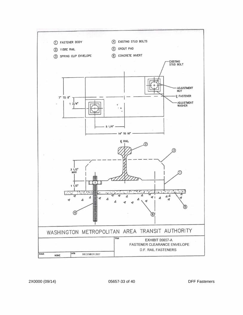
1. For retrofit construction, the fastener body anchorage assembly shall provide for two fully threaded studs, each 7/8 inch in diameter, for securing the fastener to the epoxy grout pad and concrete track bed. As shown in Exhibit A the anchorage assembly bolts shall be located in the upper right-hand quadrant and low left-hand quadrant of the rail fastener as referenced along the centerline of rail. The rail fastener shall also be designed to be capable of being anchored by placement over existing 7/8-inch threaded stud bolts in lieu of the anchor bolts and female anchor inserts.
2. For new concrete plinth construction, the fastener body anchorage assembly shall be comprised of two epoxy coated female type anchorage inserts for embedment into the concrete plinth and two anchor bolts for securing the fastener to the concrete plinth. .
3. The fastener body anchorage design shall not pass through the top plate and shall anchor thru the bottom plate only.
4. The adjustment washers shall be designed so that they can be used for either the anchor bolts or the threaded studs.
5. Female Inserts with Anchor Bolts (New Construction):
a. The fastener includes anchor bolts, 7/8 inch in diameter, for securing the fastener to the concrete trackbed under a tension of 30,000 pounds per anchor bolt.
b. The anchor bolts will be threaded into female threaded inserts set in the concrete trackbed.
2X0000 (09/14) 05657-7 of 40 DFF Fasteners
c. Anchor bolts, including washers, and threaded inserts shall be considered parts of the fastener.
d. The fastener is also capable of being anchored by placement over 7/8 - inch threaded studs.
e. The anchor bolts engage not less than one inch and not more than one and one -half inches of the threaded insert in the installed position.
f. Other than the standard protective coating as applied by the bolt and insert manufacturers, no oil, sealant or other compound shall be applied to the threads.
g. Calculate the minimum bolt insertion length into the insert to provide anchorage strength
h. Submit drawings, at a minimum scale of 1:1, that demonstrates that the proposed anchor bolt and insert combination will accommodate the full range of vertical adjustment specified in this Section. Illustrate in these drawings the length of anchor bolt insertion into the insert under both the maximum and minimum shim conditions. Decrease bolt insertion length by an additional 1/16 inch under the maximum shimming condition, to allow for cases where the top of insert is recessed 1/16 inch below the top of concrete.
6. Fully Threaded Anchor Studs (Retrofits):
a. Fully threaded anchor studs shall be 7/8 - inch diameter and 11 inches long for retrofitting direct fixation trackwork anchor installations and shall conform to ASTM A449 except that chemical requirements shall conform to ASTM A325 for Type 3 bolts, with the chromium, nickel, and copper elements in such combination to achieve maximum corrosion resistance consonant with strength and hardness requirement. (See Exhibit 05658-D)
H. Restraint Properties and Rail Release
1. Indicate the restraint properties of the rail fastener in both longitudinal directions and in both lateral directions.
2. Furnish rail fasteners providing a positive means of preventing more than a total of 1/8-inch total lateral movement of the rail base relative to the fastener on each side of the rail base in the event of failure or loosening of one or both rail hold-down spring clip elements.
3. Furnish rail fasteners permitting the release of the rail hold-down spring clip elements so that the rail may be removed by lifting it vertically until it is completely free of the fastener without disturbing the horizontal or vertical alignment of the fastener body.
4. The rail hold down assembly device shall not be dependent on elastomeric components in torsion
5. Longitudinal and lateral restraint properties of the rail fastener shall be identical in both directions.
6. The stability of the rail fastener in the lateral direction shall not be dependent solely upon the strength of the bond of the elastomer to metal.
I. Dimensional and Shape Requirements
2X0000 (09/14) 05657-8 of 40 DFF Fasteners
1. Furnish fasteners that are generally rectangular in shape.
a. Include keying, peg and socket, or turned up plate edges in the bottom plate and top plate so that loss of elastomer bond does not result in complete loss of the fastener’s ability to hold track line and gauge.
2. Height:
a. The overall distance between the base of the rail fastener and the base of the rail with the rail fastener in the installed position shall be 1-1/2 inches (desired) with 1-3/8" minimum and 1-3/4" maximum distances.
b. No portion of the completely assembled rail fastener, including the rail clips and anchor bolts, shall extend any higher than 3-1/2 inches measured vertically from the base of the rail centerline.
3. Length and Width:
a. When completely assembled, the overall dimension of the rail fastener, including the elastomer, shall stay within a design envelope of 10 inch maximum in width measured parallel to the rail and 18 inch maximum in length measured normal to the rail.
J. Adjustment Requirements
1. Lateral Adjustment
a. The rail fastener body shall provide a means of 1 inch total lateral adjustment having a range of plus or minus 1/2 inch via a serrated mechanism at each anchor location. Serration shall be vertical, a minimum of 5/32 inches high and integrally cast into the bottom plate. The bottom of the vertical serration shall be raised a minimum of 1/8 inches above the top of the bottom plate. Together with a serrated adjustment washer, the system shall allow adjustment in either lateral direction in increments of 1/8 inch. Friction alone as a means of adjustment will not be permitted. The serration shall have not less than three interlocking serrations engaged in any position of lateral adjustment. The adjustment feature shall be integral with the rail anchorage assemblies.
b. Friction shall not be used as a means for adjustment or for preventing lateral movement.
c. If lateral adjustment employs serrations on any component, each serrated interface shall have at least three engaged serrations. There shall be a minimum of three linear inches of serration engagement per fastener. Serrations shall be machined or cast to a minimum depth of 1/16 inch. Cap plates, if used, shall cover the opening to any ground potential in every position of adjustment and form a reasonable seal to prevent the intrusion of dirt, metallic particles, and other material.
d. Each rail fastener shall be furnished with all components required for all specified increments of lateral adjustment. Components of the rail fastener shall not be replaced or added to the basic configuration in order to laterally adjust the rail.
e. Recesses in the rail fastener shall be free draining in all positions of lateral adjustment up to a maximum actual superelevation of 4-1/2 inches.
2X0000 (09/14) 05657-9 of 40 DFF Fasteners
2. Vertical Adjustment
a. Vertical rail adjustment capability shall be a maximum of 9/16 inch in 1/16 inch increments, provided by shims.
b. All requirements of these Specifications shall be satisfied for all increments of fastener adjustment.
K. Electrical Isolation
1. The rail fastener body shall provide an electrical leakage distance of not less than 1-1/8 inch measured from the grounded portion of the fastener to the charged portion by the most direct path that does not pass through an insulating material. The minimum distance of separation between any point of the top plate to the bottom plate shall be 2 inch and shall contain a full and complete section of elastomer material. The entire top and side surfaces of the metal plates of the fastener body shall contain a minimum coating of 1/16 inch, exclusive of the serrated area of the fastener body anchorage location.
2. Meet the insulation requirements within the body of the fastener. Separate or detachable insulating components such as rail base pads or spring clip insulators are not allowed.
3. No surface cut-outs, gaps, edge voids, or edge cut-outs are allowed that could permit an accumulation of dirt, metallic particles, or other material, which could
PART 2 – PRODUCTS
2.01 COMPONENT MATERIAL REQUIREMENTS (ALL DIRECT FIXATION FASTENERS TYPES)
A. Metal Plate Components:
1. Metal Components:
a. Both the metal top plates and bottom plates shall be one-piece ductile iron. The minimum thickness of the top plate shall be 1/2-inch and for the bottom plate 3/8 inch.
b. The ductile iron castings shall be minimum Grade 65-45-12 in accordance with ASTM A536, “Standard Specifications for Ductile Iron Castings“. The chemical composition shall meet the acceptable level per SAE J434, “Automotive Ductile Iron Castings“. The Brinell hardness when tested in accordance with ASTM E10, “Standard Test Method for Brinell Hardness of Metallic Materials“, shall be within 156-217 BH range per SAE J434.
B. Elastomer:
1. The minimum thickness of the elastomer between the top plate and the bottom plate parallel to the rail seat shall be 1/2 inch.
2. The elastomer shall be neoprene or natural rubber or a blend of neoprene and natural rubber. Fabricate the elastomer using a minimum of 51 percent natural rubber.
3. Provide a natural rubber design based on a Durometer Shore A measurement of 70 plus or minus 10, as measured in accordance with ASTM D2240 Test Method for Rubber Property – Durometer Hardness.
4. Anchor bolts shall not pre-compress the elastomer in their installed position.
2X0000 (09/14) 05657-10 of 40 DFF Fasteners
C. Rail Hold Down Assembly:
Rail clip shall be a resilient spring clip type such as the Pandrol e-2056 (left handed) and as specified herein. Spring-wedge type rail clips will not be permitted. Rail clip shoulder shall be cast as integral part of the metal top plate. Welding of the rail clip shoulder to the top plate will not be permitted.
1. Materials - Rail clips shall be forged from alloy steel bars and heat treated to achieve the minimum spring action holding power as specified herein.
2. Minimum Design Criteria:
a. Clips must be one piece, threadless and detachable.
b. There shall be two clips to each complete rail fastener assembly.
c. Holding force shall be generated by spring action.
d. Surface hardness of clips shall be between 44 and 48 HRC.
e. The range of vertical hold down force (toe load) per clip shall be between 2,100 and 3,000 lbs. with a total force range of 4,200 to 6,000 lbs. per rail seat.
f. The minimum static longitudinal slip per complete rail fastener assembly, with two clips shall be 3,000 lbs.
g. Field installation and removal of clips shall be accomplished by one man using standard track tools or by commercially available equipment.
h. Clip shall be proven design and produced by an ISO 9000 certified manufacturer with a minimum of ten years documented in-track experience in the United States.
D. Anchor Bolts
1. Anchor bolts shall be 7/8 inch diameter, heavy hex head structural bolts per ASTM A325, Type 3, with thread length per ASTM A449. Provide certification that bolts meet requirements of ASTM A325, Type 3.
2. Washer, hardened weathering steel, ASTM F436, 2” O.D., 0.94” I.D. and 1/8” thick, two per fastener body
3. Furnish 7/8-inch diameter anchor bolts of sufficient length to provide an acceptable length of insert thread engagement with 9/16 inch of vertical shims under the rail fastener.
4. All threaded elements in the fastener shall include a positive means of preventing the loosening of the element due to in-service vibrations.
5. Threaded element installation data shall include, but not be limited to, the bolt torque range in foot-pounds.
a. The torque range shall provide the minimum tension as specified by the AISC ASD Manual of Steel Construction.
6. Coat all bolts with a water resistant coating as thread protection against rusting prior to installation.
E. Female Anchor Bolt Inserts
See Specification Section 05653, Article 2.01.C.2 for insert requirements
F. Fully Threaded Anchor Studs
See Specification Section 05653, Article 2.01.C.1 for insert requirements including Exhibit 2X0000 (09/14) 05657-11 of 40 DFF Fasteners
05658 D
G. Shims
Shims shall be 1/16th thick made of galvanized A26 steel; shall provide full bearing on the bottom of the fastener; and shall not be capable of displacement without complete removal of the anchor bolts.
2.02 VIBRATION ATTENUATING DIRECT FIXATION FASTENER (EGG TYPE)
A. The Vibration Attenuating Direct Fixation Fastener or egg-type fastener shall be manufactured by Advanced Track Products, Inc. (ATP), and previously supplied to WMATA or an approved equal.
B. In addition to being highly resilient, the fastener must provide:
1. Vertical and lateral stability to the rail
2. Longitudinal restraint to the rail
3. Electrically isolate the rail from the trackbed
4. Satisfactory service life comparable to that expected of standard direct fixation fasteners.
2.03 STANDARD DIRECT FIXATION FASTENER
A. The standard direct fixation fastener shall be the LB Foster F20L0 or approved equal meeting the requirements of these specifications
2.04 STIFF DIRECT FIXATION FASTENER
A. The Stiff Direct Fixation Fastener System shall be LB Foster Model F30L0 (Approximate vertical spring rate of 300,000 lbs/inch) or equal and, except for vertical spring rate, comply with all other requirements of this specification
2.05 ZERO LONGITUDINAL RESTRAINT (ZRL) FASTENER
A. Zero longitudinal restraint fasteners shall use the same fastener body as the Standard Direct Fixation Fastener except that the rail hold down feature of the top plate may be modified to accommodate ZLR components. Zero longitudinal restraint of the rail shall be achieved by incorporating into the fastener additional components and/or modifying the rail hold down spring clips. ZLR shall not be achieved through use of lubrication or other components that have the same effect as lubrication of the interface between the rail and fastener. Except for ZLR fasteners that have a history of successful performance, the ZLR fastener shall be subjected to the Push-Pull Test and comply with the acceptance criteria specified for the Push Pull Test.
PART 3 – EXECUTION
3.01 SOURCE QUALITY CONTROL
A. Fastener Qualification Tests
1. General
a. The qualification tests specified herein shall be performed by an independent testing facility approved by the WMATA Engineer and shall be a member of the American Council of Independent Laboratories.
2X0000 (09/14) 05657-12 of 40 DFF Fasteners
Qualification testing may be performed at any test facility, including such facilities at the contractor's plant, provided they meet the approval of the WMATA Engineer and satisfy the requirements of the American Council of Independent Laboratories “Manual of Practice, Quality Control System“ - Requirements for Testing and Inspection Laboratory. Testing equipment shall be in good repair, of adequate capacity and shall be accurately calibrated. Copies of calibration certificates shall be submitted to the WMATA Engineer. The WMATA Engineer shall be notified not less than 14 days in advance of dates scheduled for quality control tests. All testing shall be performed at no additional cost to WMATA and is to be performed post-award and prior to manufacture of production quantities. Previously approved and supplied product design meeting the requirements of this specification shall be exempt from the Qualification Testing. Production Testing as specified shall be performed.
b. From a lot of not less than twenty standard direct fixation fasteners, sixteen will be selected at random by the WMATA Engineer. If additional fasteners are necessary to meet these test requirements they shall be furnished at no additional cost to WMATA.
c. Prior to testing, the Contractor shall submit shop drawings detailing the rail fastener components and a detailed description of the steps required for its complete installation as well as the replacement of individual components. Upon approval by the WMATA Engineer of the shop drawings and installation description, rail fasteners shall be fabricated for testing.
d. Before beginning any tests, a detailed description of all tests shall be submitted to the WMATA Engineer for approval. The description shall completely detail the test procedure and shall include drawings showing the relationship of the fastener and all significant components of the testing equipment, including the test block and anchor bolts.
e. Each of the fasteners selected for testing shall be carefully measured and examined to determine the compliance with these specifications and the approved shop drawings. Upon satisfactory completion of this examination eight fasteners will be retained by WMATA and the remaining eight fasteners shall be returned to the Contractor for execution of the Qualification Performance Tests by an independent laboratory.
f. Should any fastener assembly fail a test, perform the entire sequence of test on the eight new fastener assemblies. Should a fastener assembly from a sample lot fail a test, the entire lot is rejected and the Contractor is to provide a new random sample lot to the WMATA Engineer, from which a sample of eight fasteners will be returned to the Contractor for testing by the independent laboratory. If the design of the fastener must be modified to pass any test, shop drawings of the new design shall be submitted to and approved by the WMATA Engineer before retesting is continued. Manufacture at least ten fastener assemblies of the new design and perform all tests on the new fastener design. Continue the revision, approval and test cycle until the fastener assemblies are accepted. Four (4) weeks is allotted for redesign, approval, and testing commencement. WMATA reserves the right to terminate the contract for default should the Contractor fail to develop an approved fastener within a reasonable amount of time after award so as to prevent their capability of complying with the delivery schedule.
2X0000 (09/14) 05657-13 of 40 DFF Fasteners
2. Elastomer Qualification Testing
a. Each test listed below shall be performed on two specimens.
b. The specimens used for the test shall be certified by the Contractor to have been taken from the production size batch used for making the fastener and to have cured in a manner equivalent to the cure used for the fastener.
c. Prior to the testing, all elastomer specimens shall be conditioned for not less than two days at 23 degree C plus or minus 2 degree C and 50% plus or minus 5% relative humidity
d. Tests performed on specimens are:
1.) Hardness Test - The Durometer A hardness shall be between 45 and 55 as measured in accordance with ASTM D2240, “Indentation Hardness of Rubber and Plastics by Means of a Durometer”.
2.) Tensile Strength and Ultimate Elongation Test - When tested in accordance with ASTM D412, “Tension Testing of Vulcanized Rubber”, the tensile strength shall be 2,350 psi or greater and the ultimate elongation shall be 400 percent or greater.
3.) Compression Test - The elastomer shall be tested for 22 hours in accordance with ASTM D395, Method B to determine the percent of compression set. The test shall be conducted at 70 degree C. And the set shall not exceed 25 percent.
4.) Accelerated Aging of Rubber Test - In accordance with ASTM D573, “Accelerated Aging of Vulcanized Rubber“, the test sample shall be aged for 70 hours at 70 degree The percentage of decrease of tensile strength shall not exceed 25 percent; the percentage of decrease of ultimate elongation shall not exceed 25 percent; and the change in hardness, measured on the Durometer A scale, shall not exceed 10 points.
5.) Resistance to Ozone Cracking Test - Test specimens shall be prepared in accordance with Procedure A of ASTM D518, “Resistance to Surface Cracking of Stretched Rubber Components“. The test specimens shall be tested in accordance with ASTM D1149, “Accelerated Ozone Cracking of Vulcanized Rubber”, at a temperature of 40 degree C and at an ozone partial pressure of 50 mPa. The elastomer shall not exhibit any cracking when examined in accordance with ASTM D1149 at the end of a 100-hour exposure.
6.) Compression Set at Low Temperature Test - When tested at minus 10 degree C for 70 hours in accordance with ASTM D1229, “Low Temperature Compression Set of Vulcanized Elastomers”, the compression set at 30 minutes after release (t@30 reading) shall not exceed 37 percent
7.) Oil Absorption Test –
a.) One test shall be conducted with IRM 903 (No. 3) oil at 23 degree C for 70 hours. The volume change for the No. 3 oil shall not exceed 100 percent for natural rubber.
b.) A second test using a different sample shall be conducted
2X0000 (09/14) 05657-14 of 40 DFF Fasteners
with IRM 903 (No. 1) oil at 23 degree C for 70 hours in accordance with ASTM D471, “Change in Properties of Elastomeric Vulcanizates Resulting from Immersion in Liquids“, to determine the volume change of the elastomer. The volume change for the No. 1 oil shall not exceed minus 10 percent or plus 20 percent for natural rubber.
8.) Adhesion to Metal Test - This test shall be performed on specimens of elastomer which are to be bonded in the finished fastener in accordance with ASTM D429, Method A, “Adhesion of Vulcanized Rubber to Metal“, the failure must be entirely Type R (eg. Elastomer tears before bond fails). The metal substrate, preparation, adhesive and bonding process shall be the same as that used for the manufacture of the direct fixation rail fastener.
9.) Resistance to Tearing Test - When tested in accordance with ASTM D624, “Standard Test Method for Rubber Property - Tear Resistance”, the resistance to tearing shall be not less than 100 pounds per inch.
10.) Flame Spread and Smoke Generation Test - The elastomer shall be tested in accordance with ASTM E162, “Standard Test Method for Surface Flammability of Materials Using a Radiant Heat Energy Source”, to determine the Flame Spread Index.
The elastomer shall be tested in accordance with NFPA No. 258-1982, Smoke Generated by Solid Materials Test, in both the flaming and nonflaming modes to determine the Smoke Generation Specific Optical Index, Ds. The elastomer shall not exhibit any flaming drippings when tested. No acceptance criteria are specified for the Flame Spread Index, Ls and the Smoke Generation Specific Optical Index, Ds. These indices shall be reported to WMATA for information only.
11.) Electrical Resistivity Test – Tests shall be performed on a elastomer specimen and a fully assembled fastener.
Apply 500 V dc. to the elastomer specimen for three minutes. The
elastomer shall be tested and measured in accordance with ASTM D257 "Standard Test Method for D-C Resistance or Conductance of Insulating Materials", to determine the resistivity of the elastomer. Next, immerse the specimen in potable water for 70 hours at 70°C. Immediately after removal from the water immersion, without drying and with no portion of the specimen less than 35°C, test it for electrical resistance and impedance. For testing under wet conditions, immerse elastomer in potable water with a resistivity of 1,000 to 1,500 ohm-cm. Adjust resistivity of potable water if required by addition of sodium chloride. The minimum volume resistivity under dry condition shall be 1012-ohm-cm and 1011_ ohm-cm under wet condition Refer to Article 3.03.B for Electrical Resistivity Tests on a fully assembled Fastener
2X0000 (09/14) 05657-15 of 40 DFF Fasteners
12.) Water Absorption Test - The elastomer shall be tested in accordance with ASTM 0570, "Standard Test Method for Water Absorption of Plastics" , to determine the change in weight of elastomer due to absorption of water. Immerse specimens in distilled water for 24 hours at a temperature of 23 degree C prior to testing. The elastomer shall have a maximum increase in weight of 1.0 percent.
13.) Rheology (Cure and Strength Indicator) Test-
a) Test the elastomer in accordance with ASTM 02084. b) During qualification testing a cure curve shall be
developed based on the rheology test results for approval by the Contractor. Specification limits shall be established at several points along the curve for approval by the Contractor.
c) During production testing the cure curves shall be compared to the qualification test cure curve. The production test curve shall be within the specification limits.
14.) Specific Gravity Test -
a) Test the elastomer in accordance with ASTM 0297 b) During the qualification testing the specific gravity of the
elastomer shall be determined. During the production testing the specific gravity shall be plus or minus 0.02 of the specific gravity determined during the qualification testing.
3. Fastener Body Metal Testing
a. Prepare three Charpy impact test specimens in accordance with ASTM E23, “Standard Method for Notched Bar Impact Testing of Metallic Materials“, from the same metal used for the top and bottom plates of the fastener body. Each metal sample shall have met the minimum impact requirements and be approved by the WMATA Engineer before fastener assembly qualification testing proceeds.
b. Conduct a Charpy impact test on each specimen at a temperature of 21 degree C in accordance with ASTM E23. The fracture energy shall be greater than three foot-pounds. The test report shall include all the information required by ASTM E23. The fracture energy shall be greater than 3 foot-pounds for irons and 15 foot-pounds for steel.
c. High Frequency Resonance Test
1.) Suspend the top plate with a nylon, hemp, polyethylene or cotton rope, or an elastomer band of sufficient strength to support the top plate without failure. Mount an accelerometer of mass not greater than 0.05 kg at the center of the rail seat area, with an axis of sensitivity normal to the rail seat. The accelerometer signal shall be appropriately conditioned with a charge amplifier or voltage preamplifier and analyzed with a minimum 400 line spectrum analyzer, while striking an end of the top plate with a
2X0000 (09/14) 05657-16 of 40 DFF Fasteners
hammer in a direction normal to the rail seat plane.
2.) The frequencies of the top plate’s modes of vibration, identified by maxima in the spectrum of the response of the top plate to hammer impacts, shall be greater than 600 Hz.
d. Corrosion Process: Reference Article 3.04.E
e. Heat Aging Process: Reference Article 3.04.F
4. Fastener Assembly Testing
a. Perform the following rail fastener testing at no additional cost to WMATA using the test procedures as prescribed herein.
1) Static Tests (Exhibit E):
a) Loads, as described in the tests, are per fastener and shall be doubled during performance of each test.
b) Vertical Load Test: Perform testing in accordance with Article 3.02.A herein.
c) Lateral Load Test: Perform testing in accordance with Article 3.02.C herein.
d) Vertical Uplift Test: Perform testing in accordance with Article 3.02.B herein.
e) Longitudinal Restraint Test: Perform testing in accordance with Article 3.02.E herein.
f) Lateral Restraint Test: Perform testing in accordance with Article 3.02.D herein.
2) Electric Tests: Perform all tests on single fasteners.
a) Voltage Withstand Test: Perform testing in accordance with Article 3.03.A herein.
b) Electrical Resistance and Impedance Tests: Perform testing in accordance with Article 3.03.B herein.
c) Electrical Impedance Test: Perform testing in accordance with Article 3.03.C
3) Life Cycle Tests (Dynamic): Use a separate fastener for each test.
a) Dynamic to Static Stiffness Ratio Test: Perform testing in accordance with Article 3.04.D herein.
b) Loads, as described in the tests, are per fastener and shall be doubled during performance of each test.
c) Vertical and Lateral Repeated Load Test: Perform testing in accordance with Article 3.04.A herein.
d) Repeated Load Test with One Anchor Bolt: Perform testing in accordance with Article 3.04.B
e) Uplift Repeated Load Test: Perform testing in accordance with Article 3.04.C
f) Push-Pull Test: Perform testing in accordance with Article 3.04.D
2X0000 (09/14) 05657-17 of 40 DFF Fasteners
g) Corrosion Process: See Article 3.04 E
h) Heat Aging Process: See Article 3.04 F
4) Anchorage Assembly Tests:
a) Restrained Pull-Out Test: Perform testing in accordance with Article 3.05.A
b) Unrestrained Pull-Out Test: Perform testing in accordance with Article 3.05.B
c) Torsional Test: Perform testing in accordance with Article 3.0.5C
b. Temperature
Before commencing, and during all tests, the fastener shall be stabilized at an ambient temperature of 22 degrees C, plus or minus 5 degrees C unless otherwise specified
c. Testing Plan
1) Tests specified herein shall be performed in accordance with the approved test plan.
2) The Contractor shall notify the WMATA Engineer fourteen days in advance of the commencement of testing including preparation of the test equipment for testing.
3) Testing shall be performed in the presence of the WMATA Engineer unless otherwise approved in writing by the WMATA Engineer.
d. Test Set-Up and Preparation
1) Except as otherwise specific herein, each test shall be performed on two completely assembled rail fasteners at 30-inch center to center spacing, with a section of 115RE rail not less than 42 inches long. The rail loading and measuring points shall be as specified for each test and as shown on Exhibit C.
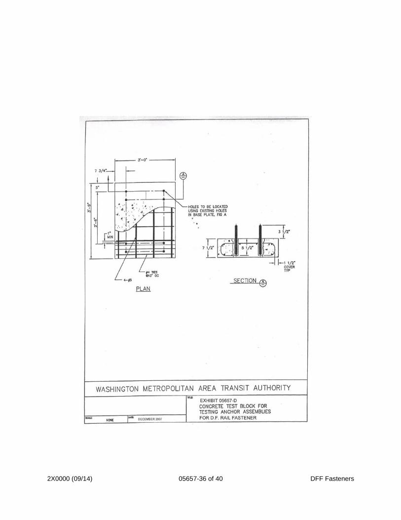
2) The fastener shall be assembled as shown in the approved shop drawings and installation description, and all threaded elements shall be tensioned as specified. The test fasteners shall be mounted on a concrete test block and anchored with 7/8 inch diameter ASTM A325, “Standard Specifications for Structural Bolts, Steel, Heat Treated, 120/105 ksi Minimum Tensile Strength”, threaded stud bolts to simulate field installation. The anchorage shall not fail under loadings imposed by any test specified below.
3) Except for specific tests noted herein, eight fasteners complete with the modified rail section as shown in Exhibit A and of length as determined shall be used
4) Before assembly, the fasteners shall be clean and dry. 5) The fasteners shall be spaced one inch apart 6) The fasteners shall be mounted and anchored on a test block and
the spring clips shall be positioned to hold the rail section. 7) The anchor bolts shall be torqued to 300 foot-pounds. 8) All reactions to load shall be through the fasteners to the test
block. 9) The test block shall be of reinforced concrete with female
threaded inserts cast or set on it to receive the 7/8-inch fastener
2X0000 (09/14) 05657-18 of 40 DFF Fasteners
anchor bolts. The top surface of the test block shall be a flat plane with a wood float finish and with the face of the inserts set parallel to the surface with a tolerance of plus zero above and minus 1/32-inch below the surface. a) Concrete: The shall have a minimum 28 day strength of 4,000
pounds per square inch as determined from standard test specimens taken in accordance with ASTM C31 and ASTM C172 and cured and tested in accordance with ASTM C39.
b) The reinforcing steel shall be epoxy coated Grade 60 per ASTM A615, “Standard Specifications for Deformed and Plain Billet Steel Bars for Concrete Reinforcement” and shall be placed as shown in Exhibit D.
c) Inserts: i. Two pairs of threaded stud bolts shall be drilled and
epoxied into the concrete test block. ii. The stud bolts shall project 3-1/2 inches out from the
top surface of the concrete. iii. The stud bolts shall be positioned as they would be in
track for two fasteners 30 inches apart measured parallel to the rail.
iv. The holes for the dowels shall be 1-1/8 to 1-3/4 inch diameter and 5-1/2 inches deep.
v. The epoxy to be used shall provide a minimum unrestrained pullout strength of 20,000 pounds. As an alternate, the stud bolts may be replaced with 7/8 inch anchor bolts and female inserts epoxy grouted into the concrete block.
vi. Inserts shall be of corrosion resistant steel threaded to 1-1/2 inch depth to receive ASTM A325 7/8-inch bolts and shall meet 40,000-pound bolt load.
vii. Washer face bearing of the insert against the fastener shall be equal to the bearing area of an A563 heavy nut for 7/8-inch bolt.
viii. Length and anchorage configuration shall withstand 12,000 pounds unrestrained pullout and resist 250 foot-pounds torque without yielding.
ix. Inserts shall be coated with an epoxy resin insulating coating, 100-percent dry powder epoxy resins, Scotch Kote Brand Protective Resins No. 203, Minnesota Mining and Manufacturing Company; Corvel Epoxy ECB-1363A, Polymer Corporation; or equal.
e. Instrumentation
1) Instrumentation for all required deflection and rotation measurements shall be designed so as to measure each rail motion parameter relative to the test block.
2) Each instrument shall be designed to measure the motion intended with minimum effects on the data from other motions.
f. Test Sequence:
1) Eight (8) complete rail fastener assemblies are required to conduct the tests. Assemble and mount two fasteners on each
2X0000 (09/14) 05657-19 of 40 DFF Fasteners
concrete block designated as A, B, C, and D. The set of fasteners shall be subjected to the following tests as specified above.
2) Fasteners A shall undergo the Vertical and Lateral Repeated Load Test and then undergo the Repeated Load Test with One Anchor Bolt. Fasteners A shall then again undergo each Static Test without replacement of any component. For the Longitudinal Restraint Test, the fasteners shall not be disassembled from the rail after the Repeated Load Test with One Anchor Bolt, nor shall the rail hold down assemblies be re-torqued.
3) Fastener B shall be subjected to Dynamic to Static Stiffness Ratio Test, then undergo Heat Aging Process, and then retested through each of the Static Tests without replacement of any component followed by another Dynamic to Static Stiffness Ratio Test.
4) Fasteners C shall undergo Heat Aging Process and then tested for Uplift Repeated Load Test followed by Corrosion Process. Fasteners C shall then be retested through each of the Static Tests without replacement of any component.
5) Fasteners D shall be tested as specified for the Push-Pull Test. Fasteners D shall then be retested through each of the tests for Static Tests, without replacement of any component. For the Longitudinal Restraint Test, the fasteners shall not be disassembled from the rail after the Push-Pull Test, nor shall the rail hold down assemblies be re-torqued.
6) The qualification testing sequence described above is graphically shown on Exhibit 5657 E
7) The sequence shall be performed without replacement of any fastener component.
g. Starting Tests and Procedures
1.) After a test sequence is begun, it shall be completed.
2.) In the event of failure of a test rig component, the WMATA Engineer shall determine if the failure was attributable to the fastener.
3.) If the fastener did contribute to the failure, or if there is doubt, then, with the approval of the WMATA Engineer, the testing shall cease and the test report shall be submitted with all findings.
4.) If the fastener did not contribute to the failure, the component shall be replaced and
B. Production Quality Control Testing 1. General
Following successful completion of the qualification tests, acceptance of the qualification test reports by the WMATA Engineer, and start of the fastener assembly manufacturing, Production type quality control sampling and testing shall be conducted and performed by an independent testing facility approved by the WMATA Engineer and shall be a member of the American Council of Independent Laboratories. Elastomer samples and fastener assemblies shall be
2X0000 (09/14) 05657-20 of 40 DFF Fasteners
selected from regular production and subjected to testing to ensure that high quality standards are maintained and that design requirements set forth in these specifications are met through the completion of the production process.
2. Production Elastomer Tests -
a. Samples of elastomer from every mixed batch of material used in the manufacture of production fastener shall be tested to verify compliance of the elastomer batch mix with the following testing requirements:
1) Hardness Test
2) Tensile Strength and Ultimate Elongation Test
3) Specific gravity: and
4) Cure Characteristic in accordance with ASTM D2084 or an equivalent industry accepted standard.
b. Certificate of Compliance from the supplier of the elastomer shall be submitted to the Engineer guaranteeing compliance of the elastomer with requirements of these specifications.
3. Fastener Assembly Tests
a. Production quality control testing of fasteners shall be performed on two (2) fasteners from the first 50 fasteners and on two (2) fasteners from each production lot. A production lot is defined as a quantity of manufactured and completed fasteners produced in a continuous run, but not to exceed 5,000 units. As requested, fasteners may be selected for testing by the WMATA Engineer. Permanently mark the fasteners used for production testing and meeting all test requirements as production test fasteners and deliver fasteners to WMATA. These fasteners shall be subjected to the following tests:
1) Vertical Load Test
2) Vertical Uplift Test
3) Lateral Load Test
4) Lateral Restraint Test
5) Longitudinal Restraint Test
6) Voltage Withstand Test
7) Electrical Resistance Test
8) Vertical and Lateral Repeated Load Test (500,000 cycles)
b. The configuration for testing and the acceptance criteria shall be as specified above, and the value obtained for the slope of the load-deflection curve in the Vertical load Test shall be within 20 percent of that obtained in the original compliance testing.
c. The quality control tests shall commence no later than fourteen days after fabrication of the fastener. Should any fastener fail to meet the test requirements, two additional fasteners from that same production lot shall be tested. In the event any of the two additional fasteners fail, 100 percent of the remainder of the lot shall be rejected or tested and only those successfully passing all tests shall be incorporated in the final delivered quantity.
2X0000 (09/14) 05657-21 of 40 DFF Fasteners
d. In addition to the quality control tests and at the discretion of the WMATA Engineer, all components of the rail fasteners shall be subjected to full or partial testing for compliance with these specifications. The cost of all such additional testing required by the WMATA Engineer for any component that is proved to comply with these specifications will be at the expense of the WMATA. The cost of all such additional testing of any component that is proven not to comply with these specifications shall be at no expense to the WMATA.
e. Production quality control testing may be performed at any test facility, including such facilities at the contractor's plant, provided they meet the approval of the WMATA Engineer and satisfies the requirements of the American Council of Independent Laboratories “Manual of Practice, Quality Control System" - Requirements for Testing and Inspection Laboratory, and ASTM E320. Testing equipment shall be in good repair, of adequate capacity and shall be accurately calibrated. Copies of calibration certificates shall be submitted to the WMATA Engineer. The WMATA Engineer shall be notified not less than 14 days in advance of dates scheduled for quality control tests.
f. Two copies of the results of all tests shall be submitted to the WMATA Engineer within seven days after performance of the tests.
4. Acceptance - Final acceptance of production lots of direct fixation rail fasteners will be based upon the fastener and all its components complying with these specifications as determined by the WMATA Engineer, based on the results of the quality control tests and the certified statements submitted to the WMATA Engineer by the Contractor.
3.02 STATIC TESTS
A. Vertical Load Test
1. Procedures
a. A vertical load increasing in increments of 2,000 pounds to a maximum load of 32,000 pounds shall be applied downward at the center of the rail head midway between the two fasteners and normal to the rail.
b. The load shall be applied at the rate of not less than 200 pounds per minute nor more than 2000 pounds per minute.
c. For each increment of load the vertical deflection of the rail head shall be measured to the nearest 0.001 inch and recorded.
d. The load shall be removed and the final position of the rail head measured and recorded. The recorded values for vertical load vs. deflection shall be plotted on a graph as shown on Exhibit F.
2. Acceptance Criteria
a. Calculate the fastener stiffness as the slope of a straight line determined by a linear least-squares regression of the load per fastener versus each deflection for load per fastener between 4,000 pounds and 12,000 pounds. The fastener stiffness shall be within 15 percent of 140,000 pounds per inch. The load versus displacement curve shall be within the limits identified in Exhibit F.
b. The tangent to load-versus-deflection curve at each load between and including 4,000 pounds and 12,000 pounds per fastener shall be within 20 percent of the fastener stiffness determined above. For the purpose of calculation, the tangent to the load versus deflection curve at each
2X0000 (09/14) 05657-22 of 40 DFF Fasteners
deflection, Xn , and each load , Pn, are approximated as:
(Pn+1 - Pn-1)/(Xn+1 -Xn-1)
Where P is the load at deflection Xn.
c. Total deflection of the elastomer at the 15,000 pound load per fastener shall not exceed 25 percent of the uncompressed thickness. After removal of the maximum load, the fastener shall return to within 0.005 inch of its original position within one minute.
d. At no time during the tests shall a fastener component exhibit any sign of failure by slippage, yielding, fracture, or bond failure.
e. Values obtained when this test is repeated, after performance of other tests, shall be within 20 percent of the initial test values.
B. Vertical Uplift Test –
1. Procedures
a. A vertical load shall be applied to the center of the rail head midway between the two fasteners and normal to the rail, alternating from a vertical downward load to a vertical upward load.
b. The peak load per cycle shall be increased in increments of 200 pounds each cycle to 4,800 pounds.
c. The loads and deflections shall be continually measured to the nearest 0.001 inch and simultaneously recorded on a load versus time graph and a deflection versus time graph respectively.
d. The load shall be removed and the final position of the rail head measured and recorded. The reaction force to the uplift load shall be applied to the test block on which the fastener is mounted.
2. Acceptance Criteria
a. The ratio of the deflection for the total uplift test load to the deflection for the total vertical downward test load shall be between plus 5 percent and plus 135 percent of the deflection for a 4,000 pound downward vertical load as determined from the Vertical Load Test.
b. When the vertical load is continuously varied from vertical downward loads to uplift loads, there shall be no indication of backlash or free play at times when the load or the deflection changes direction.
c. After removal of the maximum load, the rail shall immediately return to within 0.005 inch of its original position.
d. At no time during the test shall any fastener component, including the anchorage to the test block, exhibit any sign of failure by slippage, yielding or fracture.
C. Lateral Load Test
1. Procedures
a. While applying a vertical load of 27,000 pounds downward at the center of the rail head midway between the two fasteners and normal to the rail, a lateral load, increasing in increments of 1,000 pounds to a maximum load of 16,000 pounds, at a rate of 1,000 pounds per minute, shall be applied horizontally to the rail head at a point 0.625 inch below the top of rail at the
2X0000 (09/14) 05657-23 of 40 DFF Fasteners
location of vertical load.
b. For each load increment, the lateral deflection of the rail head at a point 0.625 inch below the top of rail shall be measured to the nearest 0.001 inch and recorded.
c. The lateral load shall be removed and the final position of the rail head measured and recorded.
d. The recorded values for lateral load vs. deflection shall be plotted on a graph similar to Figure G.
2. Acceptance Criteria
a. The lateral load versus deflection curve for each fastener shall lie within the envelope shown on Exhibit G.
b. The lateral deflection of the rail head for a lateral load of 4,000 pounds per fastener shall not exceed 0.150 inch.
c. The average lateral deflection at maximum load shall not exceed 0.336 inch.
d. After removal of the load, the difference between the original and final positions of the gauge line shall not exceed 0.062 inch. At no time during the test shall any fastener component exhibit any sign of failure by slippage, yielding or fracture.
D. Lateral Restraint Test
1. Procedures
a. A lateral load increasing in increments of 1,000 pounds from zero pounds to 10,000 pounds shall be applied normal to the rail at the base of rail midway between the two fasteners.
b. The lateral deflection of the rail shall be measured at the intersection of the centerline of the fastener and the gauge line of the rail to the nearest 0.001 inch and recorded after each increment of loading.
2. Acceptance Criteria
a. At no time during the test shall any component of the fastener show signs of slippage, yielding, or fracture.
b. The difference between the original and final positions of the gauge line shall not exceed 0.062 inch.
c. The lateral deflection of the rail when fully loaded shall not exceed 0.125 inches from original gauge line of the rail.
E. Longitudinal Restraint Test
1. Procedures
a. During the longitudinal restraint test, the rail ends shall be supported on a roller or other low friction supports, properly elevated to prevent the longitudinal load from binding the rail in the fastener.
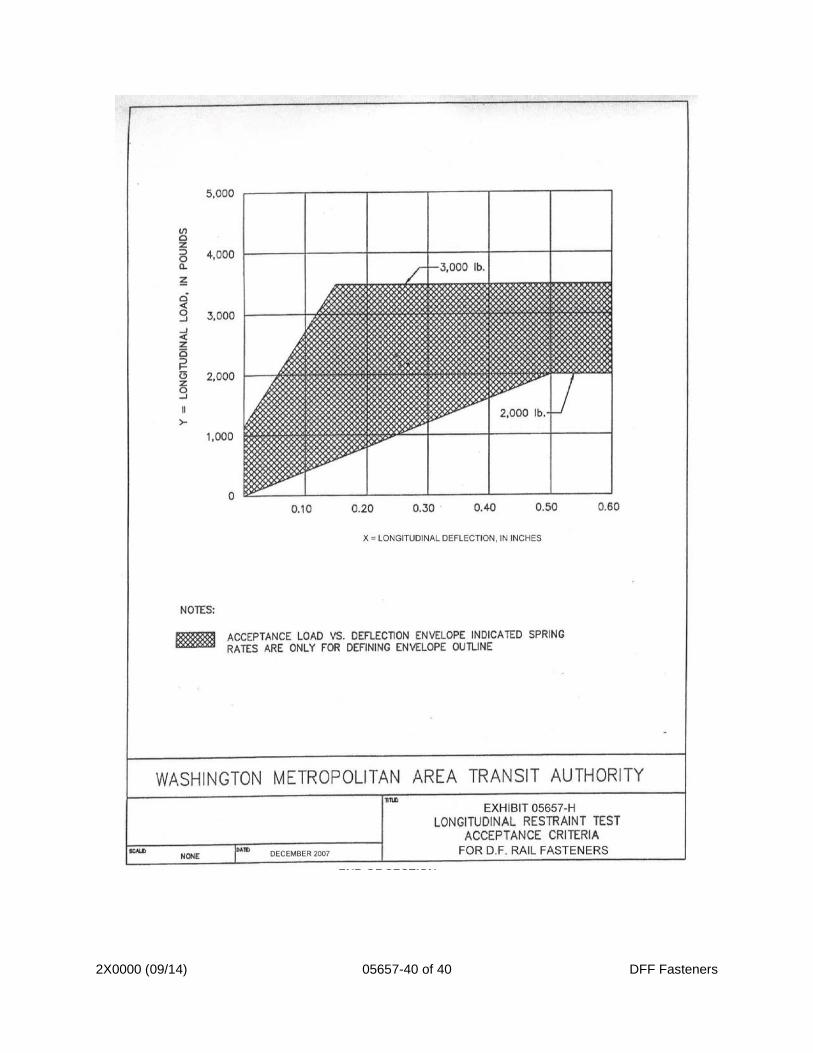
b. A load shall be applied longitudinally at the centerline of rail at the base of the rail increasing in increments of 500 pounds up to a total of 7,000 pounds or until the rail deflects 0.6 inch from the initial condition, whichever occur first.
c. The rate at which load is applied shall be approximately 1,000 pounds per minute. Each load increment shall be maintained constant at a minimum of
2X0000 (09/14) 05657-24 of 40 DFF Fasteners
30 seconds or until the longitudinal deflection of the rail ceases before increasing the load to the next increment.
d. For each load the longitudinal deflection of the rail relative to the fastener shall be measured to the nearest 0.001 inch and recorded. The longitudinal load shall be removed at slippage of rail and the final position of the rail measured and recorded.
e. The recorded values for longitudinal load vs. deflection shall be plotted on a graph as shown on Exhibit H.
2. Acceptance Criteria
a. The longitudinal load vs. deflection curve, when plotted on Exhibit H, shall lie entirely within the shaded area.
b. The difference between the original and final positions of the rail shall not exceed 0.125 inch plus the slippage distance of the rail.
c. At no time during the test shall any fastener component exhibit any sign of failure by slippage, yielding, bond failures or fracture except that slippage which may occur between the rail clip and the rail.
F. Dynamic to Static Stiffness Ratio Test
1. Procedures
a. Using the same assemblage as noted in the Vertical Load Test, Apply an oscillating downward load at the centerline of the rail head and the centerline of the fastener so as to produce a sinusoidal load alternating between 8,000 and 18,000 pounds at a rate of between 10 and 20 hertz.
b. Continuously record the load and deflection versus time on a high speed oscillograph or high speed digital recorder.
c. After a minimum of 1,000 cycles, determine the dynamic stiffness from the ratio of peak-to-trough force to peak-to-trough deflection from the recorded data.
d. Between five to ten minutes after completion of the dynamic stiffness measurement and removal of all load, apply a vertical load beginning at zero pounds and increasing in 2,000 pound increments to a maximum of 20,000 pounds, at a rate not less than 200 pounds per minute nor more than 2,000 pounds per minute, at the centerline of the fastener assembly.
e. For each increment of load between 2,000 and 20,000 pounds, record the vertical deflection of the rail head to the nearest 0.001 inch.
f. The static stiffness of the fastener shall be the difference in load divided by the difference in deflection between 8,000 and 18,000 pounds.
2. Acceptance Criteria
a. The dynamic stiffness shall not exceed 1.5 times the static stiffness.
3.03 ELECTRICAL TESTS
A. Voltage Withstand Test
1. Procedures
a. Prepare a fully assembled fastener and apply a DC potential of 15KV
2X0000 (09/14) 05657-25 of 40 DFF Fasteners
between the rail head and the metal base plate of the fastener body for one minute.
2. Acceptance Criteria
a. The elastomer shall withstand this test with no visible damage such as splits, cracks, pinholes or fractures, and no evidence of arcing, arc tracking, or other voltage breakdown.
B. Electrical Resistance Test
1. Procedures
a. Test a complete, fully assembled fastener for electrical resistance, using both the wet and dry conditions procedures as specified herein.
b. Before assembly, metal parts, anchoring devices, rail clips, elastomer surfaces, and all other ancillary parts associated with the fastener shall be clean and dry.
c. Assemble the fastener with a section of 115-pound RE rail, not less than 1 foot in length.
d. Mount a completely assembled fastener on 1/4 inch thick metallic ground plate sized to extend 2 inch beyond all edges of the fastener.
e. Use anchorage assemblies supplied, or similar to those for use in actual field installation, to mount the fastener to the ground plate.
f. Use the same number of bolts (or other device) that will be used to anchor the fastener in-service.
g. Verify that improper assembly and other causes do not make the parts that are in electrical contact exhibit excessive contact resistance; including, but not necessarily limited to, the following contact points:
1) Rail-to-rail plate interface.
2) Rail hold-down assembly (clip) and rail.
3) Anchor bolts and bottom fastener plate (if present).
4) Anchor bolts and ground plate.
h. Dry Resistance Test
1) Procedures
a) 24 hours prior to testing, store the assembled fastener in a clean, dry environment with ambient temperature of 60F to 80F and 50 to 70 percent humidity.
b) Apply 100 volts DC between the rail head and the ground plate for three minutes.
c) Measure the applied voltage and the resulting current flow, or directly measure the resistance with an accuracy of plus or minus two percent.
2) Acceptance Criteria
a) The minimum resistance for 100 volts DC is 20 megohms.
i. Wet Resistance Test
1) Procedures
a) Perform this test on the same fastener that passed the
2X0000 (09/14) 05657-26 of 40 DFF Fasteners
Dry Resistance Test. Place the assembled fastener in a nonmetallic trough or suitable container.
b) Size the container such that there is a minimum of two inches between the sides and bottom of the fastener/ground plate assembly and sides and bottom of the container.
c) Pour water into the container to a level midway up to the rail web covering all surfaces of the fastener.
d) Maintain this level of immersion for 10 minutes. The water resistivity shall be 1,000 to 1,500 ohm-cm (use potable water and adjust resistivity by addition of sodium chloride).
e) Ambient temperature of fastener surfaces (prior to immersion), water, and air shall be 60 to 80 degrees Fahrenheit.
f) Relative humidity shall be 50 to 70 percent.
g) Drain water from container to a level 2 inch below the ground plate, and without drying or otherwise disturbing the fastener, apply 100 volts DC to the rail head and ground plate and calculate the resistance within 15 seconds. Repeat measurement and calculation every five minutes for the first hour and every ten minutes for the second hour.
2) Acceptance Criteria
a) The minimum resistance for 100 volts DC is one megohms for the average of three consecutive readings within two hours after draining.
b) The difference between each of the three readings and the average reading shall not exceed 10 percent of the average reading.
C. Electrical Impedance Tests
1. Procedures
a. On a fully assembled fastener, apply a potential of 50 volts AC to the rail head for three minutes for each increment of measurement for frequencies from 20Hz to 10kHz, in increments of 20Hz up to 100 Hz, 200 Hz to 1,000 Hz, and 2,000 Hz up to 10kHz.
b. Measure the impedance after three minutes with an accuracy of plus or minus two percent and record for each frequency.
2. Acceptance Criteria
a. The minimum impedance for any frequency between 100 hz through 10 khz shall not be less than 9,500 ohms
3.04 LIFE CYCLE TESTS A. Vertical and Lateral Repeated Load Test
1. Procedures
a. Loads shall be applied to the rail head in such a manner as to produce a 2X0000 (09/14) 05657-27 of 40 DFF Fasteners
vertical downward load of 28,000 pounds, and lateral loads midway between the two fasteners, 0.625 inch below top of rail, of 8,000 pounds to the gauge side of the rail head and 5,000 pounds to the field side of the rail head.
b. The application of the lateral loads shall be alternated, each combined with alternate application and release of the vertical load, a total of three million complete cycles. Application of the field side load and then the gauge side load with two applications of the vertical load constitutes one cycle.
c. The frequency shall be regulated to prevent the temperature of the components from exceeding 70 degree C. Re-torqueing of threaded elements subsequent to the completion of 500,000 cycles of loading will not be permitted without the written approval of the WMATA Engineer.
2. Acceptance Criteria
a. The fastener shall withstand the three million cycles of load application with no evidence of failure by slippage, yielding, wear, grooving or fracture at any time during the test.
B. Repeated Load Test with One Anchor Bolt
1. Procedures
a. After completion of the Vertical and Lateral Repeated Load Test, the fastener shall be reassembled as specified using only the original components previously subjected to testing.
b. The Vertical and Lateral Repeated Load Test shall then be repeated with a minimum of 15,000 cycles with the gauge side anchor bolt loosened to a minimum of 1/4 inch gap.
2. Acceptance Criteria
a. The fastener and concrete block shall withstand the 15,000 cycles of loading with the gauge side anchor bolt loosened with no evidence of failure by slippage, yielding or fracture.
C. Uplift Repeated Load Test
1. Procedures
a. The rail fasteners, fully assembled as specified above, shall have loads applied to the rail head in such a manner as to produce alternating vertical downward load of 20,800 pounds and a vertical upward load of 4,800 pounds at the centerline of the rail and midway between the two fastener normal to the rail.
b. The application of the two vertical loads shall constitute one complete cycle and shall be applied for a minimum of 1.5 million cycles.
c. The frequency shall be regulated to prevent the components' temperature from exceeding 70 degree C.
d. Re-torqueing threaded elements subsequent to completion of 500,000 cycles of loading will not be permitted.
2. Acceptance Criteria
a. The fastener shall withstand 1.5 million complete cycles of load application with no evidence of failure.
b. Upon visual inspection, no component of the fastener, shall exhibit any
2X0000 (09/14) 05657-28 of 40 DFF Fasteners
evidence of failure by yielding, slippage or fracture.
c. The rail shall exhibit no evidence of wear of grooving that would contribute to a failure of the rail under operating conditions.
D. Push-Pull Test
1. Procedures
a. During the Push-Pull Test, the rail ends shall be supported on rollers or other low friction supports, properly elevated to prevent the longitudinal load from binding the rail in the fasteners.
b. A cycling longitudinal load shall be applied to the centroid of the rail at one end to deflect the rail plus and minus 3/4 inch about the initial position for a total of 50 cycles.
c. Immediately afterward, a cycling load equal to 80% of the ultimate slippage loads as recorded in the longitudinal restraint test shall be applied for a total of 25,000 pushing and pulling cycles.
d. Repositioning of the rail clips at any time will not be permitted.
2. Acceptance Criteria
a. The fastener shall withstand 25,000 cycles of loading with no evidence of failure.
b. Upon visual examination, no component of the fastener, shall exhibit any evidence of failure by yielding slippage or fracture, except that slippage may occur between rail clips and rail but not between rail clips and the fastener body.
c. The rail shall exhibit no evidence of wear or grooving that would contribute to rail failure under operating conditions.
d. For ZLR fasteners the 25,000 cycles of loading shall require a load of less than 300 lbs to cause the rail to slip thru the ZLR fastener.
E. Corrosion Process
1. Procedures: Expose the fastener body, without loose components, to a five percent solution in accordance with ASTM B117, “Standard Test Method for Salt Spray (Fog) Testing”, for 500 hours.
2. Acceptance Criteria
a. This is a conditioning process for the fasteners that will be further tested as indicated in Exhibit E
F. Heat Aging Process
1. Procedures: Fully assemble a fastener as specified above except the anchor bolts need not be installed and age the fastener in an air oven for a period of 166 hours at a temperature of 70 degree C using the aging methods specified in ASTM Designation D573, "Accelerated Aging of Vulcanized Rubber by the Oven Method".
2. Acceptance Criteria
a. This is a conditioning process for the fasteners that will be further tested as indicated in Exhibit E.
3.05 ANCHORAGE ASSEMBLY TESTS
2X0000 (09/14) 05657-29 of 40 DFF Fasteners
A. Fastener Anchor Bolt Insert Pull-Out Test
1. Inserts shall be installed according to the work plan in each of two areas of existing concrete trackbed exhibiting different invert conditions as directed by the Engineer. The sites selected and witnessed by the Engineer will be chosen to demonstrate the temperature and wetness limits of the anchoring material.
2. A restrained test shall be performed in each area, in which a 3-1/2 inch square by 1/2 inch thick steel plate, with a 0.9687 inch diameter hole in the center shall be placed over insert on the concrete trackbed. The insert bolt shall be installed and then have an upward vertical load applied, bearing against the steel plate, until a load of 40,000 pounds occurs. The load shall then be released. Six inserts and bolts in each area shall be tested in this manner.
3. For the unrestrained test, the steel plate shall be removed. The insert bolt shall again have an upward vertical load applied, in such a manner that no vertical load is applied to the concrete trackbed within a radius of six inches from the insert until a load of 6,000 pounds is attained.
4. Testing shall be no additional cost to WMATA.
5. Acceptance Criteria for Insert Pull-Out Testing
a. During the restrained test there shall be no evidence of failure of the insert anchoring system before a load of 40,000 pounds is attained.
b. During unrestrained test there shall be no evidence of failure by slippage or cracking of the insert anchoring material before a load of 6,000 pounds is attained.
B. Anchor Stud Pull-Out Test
1. Fully Threaded Anchor Studs shall be installed according to the work plan in each of two areas of existing concrete trackbed exhibiting different invert conditions as directed by the Engineer. The sites selected and witnessed by the Engineer will be chosen to demonstrate the temperature and wetness limits of the anchoring material.
2. A restrained test shall be performed in each area, in which a 3-1/2 inch square by 1/2 inch thick steel plate, with a 0.9687 inch diameter hole in the center shall be placed over insert on the concrete trackbed. The fully threaded anchor stud shall be installed and then have an upward vertical load applied, bearing against the steel plate, until a load of 20,000 pounds occurs. The load shall then be released. Six inserts and bolts in each area shall be tested in this manner.
3. For the unrestrained test, the steel plate shall be removed. The fully threaded anchor stud shall again have an upward vertical load applied, in such a manner that no vertical load is applied to the concrete trackbed within a radius of six inches from the insert until a load of 14,000 pounds is attained.
4. Testing shall be no additional cost to WMATA.
5. Acceptance Criteria for Fully Threaded Anchor Stud Pull-Out Testing
a. During the restrained test there shall be no evidence of failure of the fully threaded anchoring system before a load of 20,000 pounds is attained.
2X0000 (09/14) 05657-30 of 40 DFF Fasteners
b. During unrestrained test there shall be no evidence of failure by slippage or cracking of the anchor stud anchoring material before a load of 14,000 pounds is attained.
C. Torsion Test
1. Procedures
a. Subject an anchor bolt to a torque of 600 foot-pounds.
b. Hold the load for three minutes and release.
c. Repeat test on one other anchor bolt.
2. Acceptance Criteria
a. No evidence of failure of the bond between inserts and concrete on either of the two anchor bolts.
3.06 DIRECT FIXATION MOLDING REQUIREMENTS
A. Contractor’s name or trademark shall be molded into the elastomer.
B. Each cavity in a mold shall have a cavity identification mark which is molded into the elastomer. If more than one mold is used, then each cavity in a mold shall have a mold identification mark which is molded into the elastomer.
C. Each molding cycle which produces one or less fasteners from each cavity in a mold is a heat.
D. Consecutive heats from a mold shall be numbered consecutively.
E. The elastomer’s production batch number and the heat number shall be marked on each fastener in a permanent manner. The marking shall be visible in the installed position.
F. The location and method of marking of identification data shall be shown on a shop drawing.
G. In an orderly manner, each mold/heat/cavity permutation shall be assigned a unique sequential part number and part numbers shall be assigned to lots.
H. A tabulation of lot, part, batch, mold, heat and cavity shall be developed as part of the Quality Assurance Program.
3.07 MANUFACTURING TOLERANCES
A. Manufacturing tolerances for the fastener shall be as shown in Table 1.
Table 1 - Direct Fixation Fastener Manufacturing Tolerances
DIMENSION
TOLERANCE
Length and width
Plus or minus 1/8 inch
Height
Plus or minus 1/32 inch
Squareness
All angles within plus or minus 1/32 inch
Centering of holes
Plus or minus 1/32 inch
2X0000 (09/14) 05657-31 of 40 DFF Fasteners
Diameter of holes
Plus or minus 1/32 inch
Durometer Shore A
Plus or minus 5
Serration depth
Plus or minus 1/64 inch
Serration spacing
Plus or minus 1/64 inch
Width between shoulders at rail base
Plus 1/16 inch or minus zero inch
3.08 DELIVERY, HANDLING AND STORAGE
A. Fasteners shall be packed and shipped in a manner that shall prevent a load on any fastener from exceeding 1,000 pounds.
B. Fasteners shall not be stored by the Contractor in a wet location or where the ambient temperature will exceed 120 degree F.
C. Fasteners shall be packaged on wood pallets and wrapped in minimum 6 MIL plastic to permit outdoor storage in a secured area. Rail hold-down assemblies, shoulders, bolts, nuts and other loose items shall be packaged by component type in secure shipping kegs or boxes and clearly identified. The method and materials of packaging shall be submitted for approval by the WMATA Engineer.
D. The Contractor shall replace all fasteners damaged during packaging, pre-delivery storage and shipping without additional cost to the Authority.
E. Fasteners shall be delivered FOB to Authority furnished storage sites as directed by the WMATA Engineer to the Washington Metropolitan area. Unloading and final storage will be by others. Provide the WMATA Engineer two week notice prior to any fastener delivery.F. Fasteners used in the production quality control testing shall be packed and labeled separately from the rest of their lot.
PART 4 - MEASUREMENT AND PAYMENT
4.01 MEASUREMENT
A. Measurement of work specified in this section will be made in the following manner:
1. No separate measurement.
4.02 PAYMENT
A. Compensation for work specified in this Section will be made in the following manner:
1. Included in the price of the work of which it is a part.