74
Extended Use of Existing Rail Infrastructure Lennart Elfgren Luleå University of Technology Final Workshop Paris, September 30, 2014

Extended Use of Existing Rail Infrastructure
Lennart Elfgren
Luleå University of Technology
Final Workshop
Paris, September 30, 2014

Outline – Extend Life
• Background
• Assessment - Examples
• Strengthening - Examples
• Conclusions – Open questions
The better you understand a structure
– the longer service life can be achieved
-

MAINLINE Objective:
Increase service life and capacity of existing railway infrastructure
The “Harry Potter Bridge” at Glenfinnan in Scotland.
Built with in concrete without reinforcement 1897-1901.

Iron ore in
Northern
Scandinavia
The ore was first transported
with reindeers.
1888 Railway line, 14 ton
Axle load increases
1955 25 ton
1998 30 ton
2015 32,5 - 35 ton ?

114 bridges built 1900 - 2014
Fatigue capacity tested at LTU
1995
Iron Ore Line
Fatigue capacity tested at LTU 1995

A train has 68 wagons
each with ca 100 ton ore
12 trains/day transport about
25 Mton/year (increase to 40)
Maintenance cost
~ 45 k€/km, year
Has inspired three EC projects:

Four Reports on Life Extension
Benchmark, D1.1
Assessment
Methods, D1.2
Development,
Case Studies,
D1.3
Guideline, D1.4

Participants
• UIC, Paris
• NR, London
• Uminho, Guimarães
• LTU, Luleå
• UPC, Barcelona
• Skanska, Prague
• Jacobs/SKM, London

Outline – Extend Life
• Background
• Assessment - Examples
• Strengthening
• Conclusions – Open questions

Assessment – Three Phases

Four case studies
Åby
Rautasjokk Kiruna
Haparanda

Södra Rautas
20 km NW Kiruna
1902, truss 1962
Åby Älv
50 km W Piteå
1894, truss 1957

Global view of the E11 strain of deformed Åby Bridge
under 250 kN axle load (including self-weight)

Support strain – Abacus model

Loading to failure

Loading to failure – Abacus model

Test Results

Final Failure

Surviving Brittle Member Failures

Results
0
2
4
6
8
10
12
14
16
18
20
1,9 2 2,12,22,32,42,52,62,72,82,9 3 3,13,2
Qmax
NormQmax
0
1
2
3
4
5
6
7
8
9
-0,1 6E-16 0,1 0,2 0,3 0,4 0,5 0,6
Tota
l ap
plie
load
(x1
03 K
N)
Deflection (m)

Robustness to corrosion
Element type 1
Element type 3 Element type 2
Element type 4
Element type 1
415
320
16
20
Element type 2
402
300
16
21
336
Element type 3
16
16
435
250
373
12
Element type 4

Tunnels
Tunnel Condition Monitoring Index (TCMI)
Reliability-based methods
Risk and robustness assessment

Track Earthwork

Transition zone slab - Sikån
Under Seeper
Pads (USP) may
be more efficient

Outline
• Background
• Assessment - Examples
• Strengthening - Examples
• Conclusions – Open questions

26
Repair and Strengthening. First step: Selection of Materials
Concrete Metallic Masonry
Box girder Trough Beam/Slab Arch
Second step: Selection of bridges, for example reinforced concrete
Columns
Beams Or/and structural elements

27
View Section
Section
A
B
B
A
Photo(s)
Third step: Focus on strengthening needs – a detailed description
This is then related to method descriptions and case studies
Method Descriptions
Case Studies
Easy to add-on
• Additional Methods • Case studies • Design examples • Results from monitoring • Damages
Prepared for databases

Trough bridge in Haparanda
Licentiate Thesis by Jonny Nilimaa http://pure.ltu.se/portal/files/41761237/Jonny_Nilimaa.Komplett.pdf
Increase axle load from 25 to 30 ton
Overuse:
- Flexure 1.25
- Shear 1.03
Prestress slab to increase shear capacity

Prestressing Haparanda Bridge
1) an anchoring nut
2) an anchoring plate and
3) load-distributing wedge
Prestressing setup including:
1) the steel frame,
2) the hydraulic jack and
3) the extra prestressing nut.
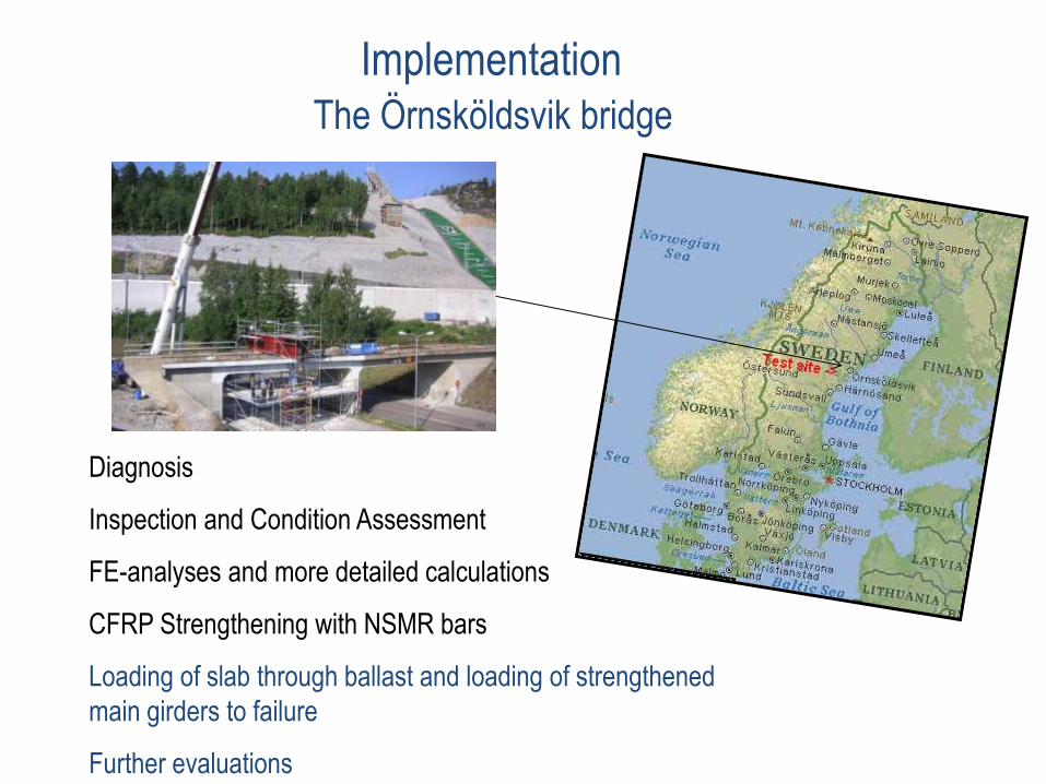
The Örnsköldsvik bridge
Diagnosis
Inspection and Condition Assessment
FE-analyses and more detailed calculations
CFRP Strengthening with NSMR bars
Loading of slab through ballast and loading of strengthened
main girders to failure
Further evaluations
Implementation

Ornskoldsvik Mellansel
6000 2000
6000 2250 1750
2250 1750
73°17''
R=
30
0m
R=40m
loading beam
N
north sidewalk line
south sidewalk line
5800 11919 12174 6400
36293
>4500 mm
6146
1423 1693 1693 1423
2900
35
0
11
00
623 623
4900
70
0
+2.65
+1.95
The Örnsköldsviks bridge
Implementation

First the
strengthening
design was
carried out
Strain based design. Resulted in 9 bars (9x100mm2/beam). Ef = 250 GPa. Moment
capacity of 11.6 kNm per beam
'
' 'sf uo s s s s y s f f f
x dM A E x d A f d x E A h x
h x
Implementation The Örnsköldsviks bridge - 2006

Background
Sawing for Strengthening.
(Near Surface Mounted CFRP Rods)
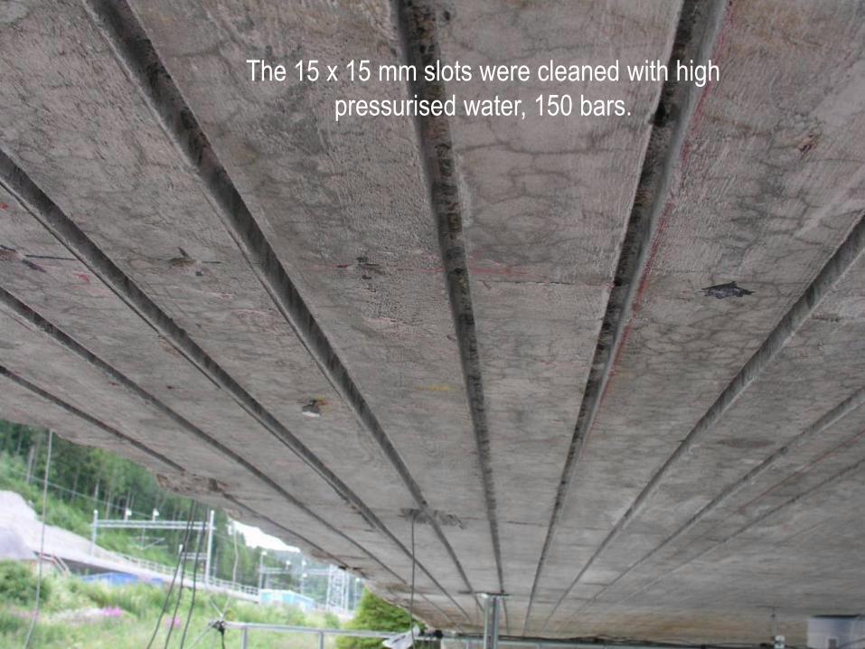
The 15 x 15 mm slots were cleaned with high
pressurised water, 150 bars.


Open time: ca 50 min


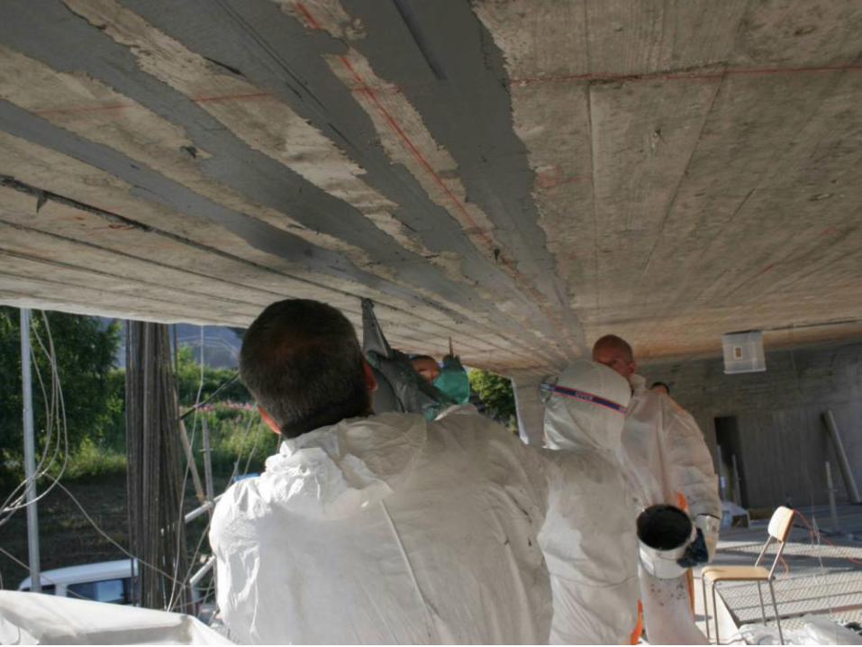


Final strengthening result

CFRP cut-off end
“Fish-bone pattern”

Implementation The Örnsköldsviks bridge - 2006

Outline
• Background
• Assessment - Examples
• Strengthening - Examples
• Conclusions – Open questions

Conclusions – Life Extension
Use Refined Assessment Methods:
- Robustness
- Probabilistic Methods
- Proof load
Strengthen with
- Prestressing and Post-tensioning
- CFRP; Carbon Fibre Reinforced Polymers:
- Near surface mounted reinforcment (NSMR)
The better you understand a structure
– the longer service life can be achieved
-

49
Test of the Kiruna Mine Bridge Preliminary Program 2014-05-10
Niklas Bagge, Jonny Nilimaa,
Thomas Blanksvärd, Björn Täljsten & Lennart Elfgren


51
Geometry & Materials
• 121.5 m prestressed concrete bridge
• Continous beams with 5 spans
• Built 1960
• Concrete 30.40 MPa
• Rebar 400 & 600 MPa
• BBRV St1450/1700
18000 20500 29350 27150 26500
1 2 3 4 5 6
Spannlängder avser brons centrumlinje
N
ELEVATION
PLAN
Spårområde E10
Mitt Norra Södra
1500 1500 12000

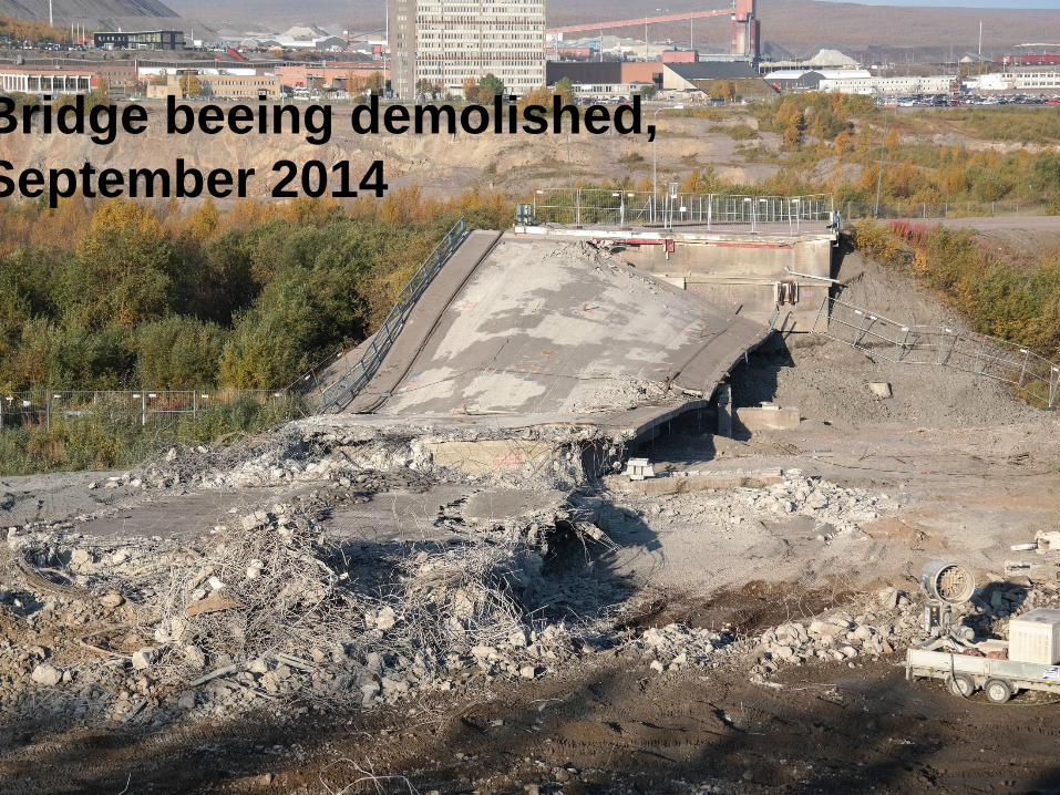
Bridge beeing demolished,
September 2014

Open questions
• How to meet increased demands on infrastructure
caused by increased loads and climate change?
• How to develop assessment methods that can be
easily used by infrastructure managers?
• How to understand the function of our infrastructure
to be able to assess and strengthen it efficiently?
• How to monitor to secure a longer life when initial
assessment is not passed?

End of Presentation
• Thank you for your kind attention!
• Questions?
The better you understand a structure
– the longer service life can be achieved


RAMS
LCC/RAMS Matti Rantatalo 58
(SS-EN_13306_2010)
MTBF
Mean Time
Between Failures
Reliability
MTTR
Mean Time
To Repair
Maintainability
Failure
MWT 1
Mean
Waiting
Time 1
Supportability
MWT
Mean
Waiting
Time 2
Restored function
Function
1
0
Availability = MTBF / Total Time

RAMS
LCC/RAMS Matti Rantatalo 59
Availability
Supportability
Maintainability Reliability
Safety
(SS-EN_13306_2010)
MTBF
Mean Time
Between Failure
MTTR
Mean Time
To Repair
MWT
Mean Waiting
Time

Subject 60 Référence / date
RAMS
• Railway RAMS • (SIS-1999-SS-EN)
• Reliability
• Availability
• Maintainability
• Safety
Maintenance
terminology (SS-EN_13306_2010)
Reliability
Availability
Maintainability
Supportability
Safety
Security
Sustainability
Supportability
RAM4S

Outline – Extend Life
• Background
• Assessment
• Strengthening
• Track and Earth work
• Conclusions – Open questions

Surviving Ductile Member Failures
column failure
due to collision
column failure
due to EQ.
System redundancy

Surviving Brittle Member Failures
Shear failure from
truck impact
Fatigue & Fracture
Damaged state redundancy

INTRODUCTION OF LCA
PERSPECTIVE

Advanced assessment: Bridges
1.- Direct application of reliability-based assessment
methods
2.- Consideration of system safety, redundancy and
robustness criteria
3.- Site-specific live loads and dynamic amplification
factors
- Traffic load, Temperature effects
4.- Incorporation of data from inspection and monitoring.
Model updating
- FEM updating
- Degradation modelling: loss of area, loss of bond
due to corrosion,…
5.- Proof load testing

Definition of redundancy/robustness
(I)
Assumed linear
behavior
LFd
LF1
LFf
LFu
Bridge Response
Damaged
system
Load Factor
First
member
failure
Ultimate capacity
of damaged
system
Ultimate capacity
of intact system
Loss of
functionality
Intact
system
Actual
behavior

Content
1. Introduction
2. Basis for design
3. Material, systems and strengthening
techniques
4. Strengthening for flexure
5. Strengthening for shear
6. Strengthening of columns
7. Extreme Loadings
- Calculation examples
- Checklists and quality control
- Typical material data
FRP Strengthening of Concrete Structures
Updated Guideline from SB

Eigenfrequencies

Reliability-based assessment: model and random
variables
Random variable Unit Mean COV (%) PDF
Yield strength MPa 220 10 Lognormal
Hardening modulus MPa 1080 25 Lognormal
Self-weight Kg/m3 7800 3 Normal
Railway traffic load (concentrated) kN 103.5 (4 loads
per rail) 10 Normal
Railway traffic load (distributed) kN/m 31.7/rail 10 Normal
Impact factor - 1.10 25 Normal

Stress (Von Mises) at maximum and ultimate loads

Plates Sheets
Rods
• Prestressed
• Non prestressed Grids, Mineral Based
Strengthening Systems
Evaluations of different CFRP strengthening systems

Strengthening of metallic structures External prestressing Thermography system
Integrated sensors
0 10 20 30 40 50 60 70
Midpoint deflection [mm]
0
20
40
60
80
100
120
140
Lo
ad
[kN
]
Reference
StrengthenedStrengthened prestress
reference defect Reference
Defect
Mineral based
CFRP
strengthening

A little more than the design case

74
Reserve Capacity The failure load 1170 ton corresponds to
1170 ton / 25 ton ≈ 47 axles
The span of 12 m has only room for 4 axles
47 axles /4 = 11,7 carriages (on top of each other)
The strengthening gives approx. 25 % of the capacity,
so without strengthening we have a capacity of
approx. 34/4 = 8,5 carriages


