AIAA-94-1294-CP EXTENSIBILITY IN LOCAL SENSOR BASED PLANNING FOR HYPER-REDUNDANT MANIPULATORS (ROBOT SNAKES) Howie Choset Joel Burdick Dept. of Mechanical Engineering Mail Code 104-44, CALTECH, Pasadena, CA 91125 ABSTRACT: This paper extends a local sensor based planning method for hyper-redundant robot mechanisms. In a previous paper, sensor feedback control methods are considered. A highly localized sensor feedback method for hyper-redundand manip- ulators is termed, partial shape modification (PSM). A PSM utilizes a mechanism's hyper-redundancy to enable both local obstacle avoidance and end-effector placement in real time. This paper considers the sit- uation in which the limits of a PSM is violated. In other words, what does the robot do when it can not only locally adapt to the environment. Local sensor based planning has been implemented on a thirty de- gree of freedom hyper-redundant manipulator which has eleven ultrasonic distance measurement sensors and twenty infrared proximity sensors. The robot is controlled by a real time control computer which com- municates with sensors through an innovative sensor bus architecture. Experimental results obtained us- ing this test bed show the efficacy of the proposed method. 1. Introduction This paper extends experimental results from [TCB] in the area of local sensor based planning for hyper- redundant robot manipulators. Recall from [ChB90b] that a "hyper-redundant" manipulator is a kinemat- ically redundant manipulator in which the degree of redundancy is very large or infinite. Such robots are analogous in morphology to tentacles, an elephant's trunk, a monkey's tail or a snake. "Sensor based planning" incorporates sensory information into some stage of a robotic motion planning, whether it be navigation, locomotion, grasping, etc. "Local Sen- sor Based Planning" fine tunes a robot's plan, based on sensor information. Local sensor based planning is useful when: (1) the robot only has a coarse knowl- edge of the world because of limited memory; (2) the robot's world model contains inaccuracies; and (3) the world is subject to unexpected occurrences or rapidly changing situations. These situations can be overcome with local sensor based planning strategies. Due to their many degrees of freedom, hyper- redundant robots are potentially superior for opera- tions in highly constrained and unusual environments encountered in applications such as inspection of nu- clear reactor cores, chemical sampling of buried toxic waste, and medical endoscopy. Hyper-redundant robots can also be used as tentacle-like grasping de- vices for capturing and manipulating floating satel- lites [ChB90c] or to enable complex "whole arm ma- nipulation." Mobile hyper-redundant robots also of- fer novel means for locomotion [ChB91a, ChB93a, ChB93b, ChB93c] in complex environments. The above mentioned applications are characterized by environments which are difficult to precisely model and which are time varying. Thus, local sensor-based motion planning schemes are vital to the realistic de- ployment of hyper-redundant robots in these applica- tions. While hyper-redundant robots have many ad- vantages for the above described applications, they have one disadvantage. Since hyper-redundant ma- nipulators have a large number of joints or actuators, small joint displacement errors can accumulate to rea- sonably large errors in the position of the tip relative to the base. Thus, the effective accuracy of hyper- redundant robots could be improved by distributing sensors along their length and employing sensor based planning schemes. Thus, local sensor based planning can be used to: (1) account for spatial uncertainty or inaccuracies in the world model used by a "global" planner to con- struct a robot plan; (2) increase the effective accuracy of a hyper-redundant robot mechanism; and (3) lo- cally adapt to rapid environmental variations, such as moving obstacles, that can not be easily or rapidly handled by a global planner. The local sensor based planning algorithm of hyper- redundant manipulators is based on the analysis found in [ChB90b, ChB91a, ChB92a, ChB92c, Ch]. This work has been demonstrated on an actual ex- tensible 30 degree-of-freedom hyper-redundant robot system. A hyper-redundant manipulator which can vary its length, within the limitations of its actuators, is termed "extensible." A more detailed account of this mechanism and its capabilities can be found in [ChB92b]. Robotic motion planning has been an important area of research. Since the introduction of configuration space methods [LoWes], several other theories have been published, some of which are summarized in [Sh,Lat]. However, these methods plan from a per- fect model of the world, which is normally unavail- able to a real robot. More recently, methods have been developed in which the robot explores the envi- ronment to gather information for the planning pro- cess [CaLi]. These approaches assume that the sen- sors provide perfect information about the environ- ment. There has been little work devoted explicitly to motion planning for robot snakes. One approach is based on the construction of tunnels through the ob- Copyright 1994 by the American Institute of Aeronautics and Atronautics, Inc. All rights reserved. 820 https://ntrs.nasa.gov/search.jsp?R=19950005137 2018-07-08T18:25:03+00:00Z
Transcript
AIAA-94-1294-CP
EXTENSIBILITY IN LOCAL SENSOR BASED PLANNING
FOR HYPER-REDUNDANT MANIPULATORS (ROBOT SNAKES)
Howie Choset Joel Burdick
Dept. of Mechanical Engineering
Mail Code 104-44, CALTECH, Pasadena, CA 91125
ABSTRACT: This paper extends a local sensorbased planning method for hyper-redundant robotmechanisms. In a previous paper, sensor feedbackcontrol methods are considered. A highly localizedsensor feedback method for hyper-redundand manip-ulators is termed, partial shape modification (PSM).A PSM utilizes a mechanism's hyper-redundancy toenable both local obstacle avoidance and end-effectorplacement in real time. This paper considers the sit-uation in which the limits of a PSM is violated. Inother words, what does the robot do when it can notonly locally adapt to the environment. Local sensorbased planning has been implemented on a thirty de-gree of freedom hyper-redundant manipulator whichhas eleven ultrasonic distance measurement sensorsand twenty infrared proximity sensors. The robot iscontrolled by a real time control computer which com-municates with sensors through an innovative sensorbus architecture. Experimental results obtained us-ing this test bed show the efficacy of the proposedmethod.
1. Introduction
This paper extends experimental results from [TCB]in the area of local sensor based planning for hyper-redundant robot manipulators. Recall from [ChB90b]that a "hyper-redundant" manipulator is a kinemat-ically redundant manipulator in which the degree ofredundancy is very large or infinite. Such robots areanalogous in morphology to tentacles, an elephant'strunk, a monkey's tail or a snake. "Sensor basedplanning" incorporates sensory information into somestage of a robotic motion planning, whether it benavigation, locomotion, grasping, etc. "Local Sen-sor Based Planning" fine tunes a robot's plan, basedon sensor information. Local sensor based planningis useful when: (1) the robot only has a coarse knowl-
edge of the world because of limited memory; (2)the robot's world model contains inaccuracies; and(3) the world is subject to unexpected occurrences orrapidly changing situations. These situations can beovercome with local sensor based planning strategies.
Due to their many degrees of freedom, hyper-redundant robots are potentially superior for opera-tions in highly constrained and unusual environmentsencountered in applications such as inspection of nu-clear reactor cores, chemical sampling of buried toxicwaste, and medical endoscopy. Hyper-redundantrobots can also be used as tentacle-like grasping de-vices for capturing and manipulating floating satel-lites [ChB90c] or to enable complex "whole arm ma-
nipulation." Mobile hyper-redundant robots also of-fer novel means for locomotion [ChB91a, ChB93a,ChB93b, ChB93c] in complex environments.
The above mentioned applications are characterizedby environments which are difficult to precisely modeland which are time varying. Thus, local sensor-basedmotion planning schemes are vital to the realistic de-ployment of hyper-redundant robots in these applica-tions. While hyper-redundant robots have many ad-vantages for the above described applications, theyhave one disadvantage. Since hyper-redundant ma-nipulators have a large number of joints or actuators,small joint displacement errors can accumulate to rea-sonably large errors in the position of the tip relativeto the base. Thus, the effective accuracy of hyper-redundant robots could be improved by distributingsensors along their length and employing sensor basedplanning schemes.
Thus, local sensor based planning can be used to:(1) account for spatial uncertainty or inaccuracies inthe world model used by a "global" planner to con-struct a robot plan; (2) increase the effective accuracy
of a hyper-redundant robot mechanism; and (3) lo-cally adapt to rapid environmental variations, suchas moving obstacles, that can not be easily or rapidlyhandled by a global planner.
The local sensor based planning algorithm of hyper-redundant manipulators is based on the analysisfound in [ChB90b, ChB91a, ChB92a, ChB92c, Ch].This work has been demonstrated on an actual ex-tensible 30 degree-of-freedom hyper-redundant robotsystem. A hyper-redundant manipulator which canvary its length, within the limitations of its actuators,is termed "extensible." A more detailed account ofthis mechanism and its capabilities can be found in[ChB92b].
Robotic motion planning has been an important areaof research. Since the introduction of configurationspace methods [LoWes], several other theories havebeen published, some of which are summarized in[Sh,Lat]. However, these methods plan from a per-fect model of the world, which is normally unavail-able to a real robot. More recently, methods havebeen developed in which the robot explores the envi-ronment to gather information for the planning pro-cess [CaLi]. These approaches assume that the sen-sors provide perfect information about the environ-ment. There has been little work devoted explicitlyto motion planning for robot snakes. One approach isbased on the construction of tunnels through the ob-
Copyright 1994 by the American Institute of Aeronautics and Atronautics, Inc. All rights reserved.
stacle field, through which the manipulator "slithers"[ChB90a, Ch]. In another work, sensor based plan-ning for highly redundant robots is based on a tactrix[ReLu]. However, this work assumes that there areperfect sensors on the robot; nor has it been imple-mented on a real robot. Hirose [HiU] implementedan "active cord" mechanism, which used tactile sen-sors to guide its motion. A previous paper [TCB]presents preliminary strategies for local sensor basedplanning, which are implementable in real time, canemploy a variety of sensors, and exploit the benefitsof hyper-redundancy.
In this paper, a local sensor based planning strategyfor hyper-redundant manipulators is extended so itcan be more accommodating. The local sensor basedplanner in [TCB] did not consider its own limitations.There, the hyper-redundant manipulator can only lo-cally adapt to a changing environment over a fixedlength of the robot. For a fixed length of robot, ahyper-redundant manipulator uses its extensibility soit can locally avoid obstacles. However, the robot canonly deform until its joint limits are met, in whichcase the hyper-redundant manipulator can no longeradapt. In other words, the robot used up all of its ex-tensibility over the fixed length. The longer this fixedlength, the more the robot can deform. However, thelonger the length, the less local the response, whichis undesireable. In the new algorithm, the length ofthe deforming part of the robot is variable, there-fore enhancing its ability to locally adapt. In effect,the manipulator uses more of its extensibility fromother parts of the robot to locally avoid objects. Ex-periments demonstrate that local sensor based plan-ning is not only useful, but also implementable inreal time with very reasonable computing power andsimple sensors.
The structure of this paper is as follows. Section 2reviews the basic framework of hyper-redundant ma-nipulator kinematics which is based on "backbonecurves." The backbone curve and its deformationis the basis for the algorithms of Section 3. We pri-marily consider algorithms for planar mechanisms, asthe experimental verification of these ideas was per-formed on a planar robot. Many of these algorithmscan be extended to the spatial case. Section 4 de-scribes the experimental setup, while Section 5 de-scribed the actual results of these experiments.
2. Background
This section reviews a hyper-redundant robot kine-matic analysis framework that forms the basis of thiswork. Recall from [ChB90b] that we assume that(regardless of mechanical implementation) the impor-tant macroscopic features of a hyper-redundant robotcan be captured by a backbone curve. A backbonecurve parametrization and an associated set of ref-erence frames which evolve along the curve are col-lectively called the backbone reference set. In thisparadigm, inverse kinematics and task planning re-duces to the determination of the proper time vary-ing behavior of the backbone reference set [ChB90b].
Similarly, local sensor based planning is equivalent inthis approach to modification of the backbone curveshape in order to accommodate impinging obstacles.
In [ChB92c], many techniques are introduced forparametrizing the backbone curve. In this paper, wewill assume that the Cartesian position of points ona backbone curve can be parametrized in the form:
/0 8= (2.1)
where s E [0, 1] is a parameter measuring distancealong the backbone curve at time t. The backbonecurve base is the point s = 0. g(s, t) is a vector fromthe backbone curve base to point s. By convention,$(0, t) = 0. if(s, t) is the unit tangent vector to thecurve at s. l(s,t) is the length of the curve tangentand assumes the general form:
l(s,t) = 1 + e(s,t) > 0. (2.2)
e(s,t) is the local eztensibility of the manipulator,which expresses how the backbone curve locally ex-pands or contracts relative to a fixed reference state.We show later on that the robot needs this extensi-bility in order to locally avoid obstacles.
The parametrization of Eq. (2.1) has the followinginterpretation. The backbone curve is "grown" fromthe base by propagating the curve forward along thetangent vector, which is varying its direction accord-ing to if(s, t) and varying its magnitude (or 'growth-rate') according to l(s, t).
Our experiments have been performed on a devicewith planar geometry. In the planar case, the back-bone curve is the locus of points:
_(s,t)- [xl(s,t), x2(s,t)] T
where
/0 szl(s,t) = l(_r,t) sinO(cr, t)d_r (2.3)
/0 8x2 (s, t) = l(cr, t) cos 0(a, t)d_r. (2.4)
O(s,t) is the angle, measured clockwise, which thetangent to the curve at s makes with the z2-axisat time t. By convention (2.4), 0(0) = 0, andzl(0) = z2(0) = 0. By comparing equations (2.1)with equations (2.3) and (2.4), it easy to see that
g(s,t) = [sin 0(s, t), cos0(_,t)] T in the planar case.l(s) and 0(s) are termed "shape functions," as theycontrol they shape of the backbone curve through theforward kinematic relations (2.3) and (2.4).
Within the context of this modeling technique, the in-verse kinematic problem, or "hyper-redundancy res-olution" problem, reduces to the determination ofthe time varying behavior of backbone curve shape
821
functionsthat satisfies task requirements. Differenthyper-redundancy resolution techniques can be foundin [ChB90a, ChB91a, ChB92a, ChB92c, Ch]. In oneapproach, which is relevant to the algorithm of Sec-tion 3, the backbone curve shape functions are re-stricted to a "modal form"
Ns NI
o(8,t)= l(8,t)=i=l i=Ne+l
(2.5)where _i(s) isa "mode function,"and ai(t)isthe as-sociated "modal participationfactor."N = No + Nzis the total number of modes, which must equalor exceeds the number of task constraints.Hyper-redundancy isresolvedinthe modal approach by con-strainingthe backbone curve toN effectiveDOF. The
{{b,}are predetermined functionschosen by the pro-grammer, and can often be selectedto incorporate
physical characteristicsof the task [Ch]. Thus, thebackbone curve geometry becomes solelya functionofthe {ai}. The inversekinematics problem reduces
to findingthe {ai} which satisfytask constraints.In
[ChB91a, ChB92c], closed form solutionsare givenfor severalchoicesof mode functions.
A continuous backbone curve inversekinematic solu-tion isused to determine the actuator displacementsof a continuous morphology robot such as one con-structedfrom pneumatic actuator bundles. For dis-cretelysegmented morphologies, such as the proto-type describedinthispaper in Section4,the contin-uous curve solutioncan be used, via a "fitting"pro-cess,to compute the actuator displacements whichcause the manipulator to exactly assume or closelyapproximate the continuous backbone curve model.The fittingtechniqueswhich are used in subsequentexamples are reviewed in [ChB91a, ChB92c].
3. Local Sensor Based Planning Algo-rithm
Local Sensor-Based Planning (LSBP) assumes thata backbone curve is somehow determined by a highlevel global planning process. The backbone curveshape is then modified in response to sensory infor-mation. LSBP does not use a model of the environ-ment, and is intended for rapid response to environ-ment changes. In order to describe the local sensorbased planning strategy,a sensor model must be de-scribed.
3.1. Sensor Models
The algorithm described below uses a very simple sen-sor model. We assume that the sensors are rigidly at-tached to the backbone curve at a fixed point. Thatis, they move with the backbone curve, and their ori-entation is a function of the backbone curve tangentat the point of attachment. The sensors are assumedto measure, along a fixed direction termed the sen-sor measurement axis, the distance to a nearby ob-stacle. The sensor measurement axis is a functionof the sensor and the backbone curve geometry (See
Fig. 1). Our sensors do not measure the distanceto the point on the obstacle which is nearest to thebackbone curve. Rather, they measure the distancewhich would actually be computed by realistic sen-sors. This simple model is representative of the in-frared and ultrasonic sensors discussed in Section 4.In addition, there is often some directional ambiguitydue to the finite width of a typical sensor's beam pat-tern. We assume that the sensor measurement axisis the centerline of the beam pattern. The distancemeasurement returned by the sensor is the nearestpoint of the obstacle lying within beam pattern cone.Since it is impossible to resolve the angular ambigu-ity, we assume that nearest point of the obstacle liesalong the beam pattern centerline.
Mcasurcmcnt Axis
/
Figure 1: Simplified Distance Mea-
surement Sensor Model
3.2. Partial Shape Modification Con-trol
This section describes a PSM planning strategy inwhich the backbone curve is approximated by a largenumber, rid, of discrete endpoints. The sensors areassumed to be rigidly attached at points along thediscretized backbone curve. There are typically manyapproximating segments between adjacent sensor at-tachments. When a sensor detects the presence of anobstacle, the backbone curve shape locally deformsin a region around the sensor. In our simulationsand experiments, nd "_ 100, and there were about 10discrete points between sensor points.
The actual response, a displacement of the approx-imating points, is determined by a local sensor re-sponse function (LSRF), which is assumed to be a dis-crete unimodal function. A unimodal function is onewhich has one local maximum, the global maximum,over its domain. The response function is "added" tothe current backbone curve, locally drawing it awayfrom an obstacle. In Figure 2, a triangle LSRF isadded to a straight backbone curve, deforming thebackbone curve away from an sufficiently close ob-stacle.
Since the robot only detects the obstacle at a sensorpoint, the reaction to the obstacle should be greatestat the sensor point, and should monotomically de-crease at points away from the sensor point. There-fore, the sensor point is the center of this unimodal
822
function,andisassumedto be farthest away from theobstacle.
The LSRF should also look like the beam pattern ofthe sensor associated with the sensor point. Typi-cally, beam patterns have a central lobe along thesensor axis, in which the obstacle likely lies. In the ex-perimental setup, the spatial resolution of the robot'sactuators is much lower than the azimuth resolutionof the sensors on the robot. Therefore, a simple tri-
angle (or cone) is a sufficient approximation to themain lobe of the beam pattern, and thus, a reason-able choice for a LRSF. Later on, it is shown that atriangle response function leads to a trivial and ef-ficient solution to LSBP for planar hyper-redundantmanipulators. So, the example displayed in Figure 2is a good example of a LSRF.
The half width of the LSRF is slightly larger than thedistance between two adjacent sensors on the back-bone curve. This way, if two adjacent sensors detectthe same obstacle, their cumulative response functionis still unimodal.
In this approximation method, the position of the dis-crete segment endpoints can be approximated by thediscretization of the continuous forward kinematicsintegral (Eq. (2.1)):
k=i
iff(s,,t) = E l(sk,t)g(sk,t) (3.2.1)k=O
l(s) and if(s) are continuous shape functions whichare specified by a global planner. They need not as-sume a modal form. Also, an endpoint may or maynot coincide with a sensor point.
A small differential change in ff(si) is:
k=i
k:O
(3.2.2)
where sk = k__ where nd is the number of discrete
points along the back bone curve. _ff is a local change
in the backbone curve tangent direction, while _rep-resents a local stretch.
The goal of this PSM method is to compute the local
perturbations, _ff and _, which deform the backbonecurve away from obstacles. The changes in backbonecurve tangent and stretch are determined from _ff,which in turn is determined by the LSRFs. The mod-ified backbone curve shape is then used by the fittingalgorithms to determine the appropriate actuator dis-placements.
Assume that at some initial time, a global plannerspecifies a backbone curve shape. Thus, ¢5/_= 0 ini-tially. For each sensor point along the backbone curvethat detects an obstacle within its response envelope,a discrete unimodal LSRF is added to (or subtractedfrom, depending upon from which direction an ob-stacle appears to be) @, the vector which containsthe prescribed changes to the backbone curve. Set-ting @(s_,t) = 0, guarantees that, within the lim-its of the discretization approximation, the end effec-tor position will not change. Setting @(s_,t) = O,
@(s,_-1,t) = 0, and _a(s_,t) = 0 guarantees thatthe end effector position and orientation will notchange. The new backbone curve can be computed
after _g and _['are determined from (3.2.1).
In the case of a planar backbone curve, (3.2.2) canbe written in matrix form:
f s_i
sv:_sp
Sp_ I
I s_
k $p8p
_lt 0 0 o ...
o I1 o o ...
ZI o Is o ...
o 11 o Is ...
: : : : •
o It o 12
I1 0 l s 0
0 Ix 0 13
0 o
o o
o o
o o
o o
In o
o In
u 1 0 0 ... 0 $ulu
_ o o .. o s_
3 0 0 .
: : : ... : s_._ ._ _ o _'_
_Y _tl till . , . 0 _13
_ 3 n"up _ t/ *_P "'" u U j
(_.2.S)
where*¢ = t), = Za t), = t),= l'(sl), and if/ = ff(si, t). The x and y compo-
nents of _f(s_,t) are respectively denoted *p_ and
@_. Similary, the x,y components of *g(si, t) are
_u_ and _u_v. _ and 5g each have 2n elements, and
_l'has n elements.
For given _f, there is not a unique solution toEq. (3.2.3). A simplified (and unique) solution for
823
(3.2.3)is obtainedbysettingl(s_,t) = 1 Vl<i<n (i.e61(si,t) -- 0). Although all of the l(s,,t) -- 1, thesnake can still use its extensibility to avoid obstaclesbecause [[gi +6if/i[ ¢ 1. In other words, the length ofthe tangent vectors are no longer constrained to haveunit length in this approximation unless additional
restrictions are employed. After setting 61(si, t) = 0and enforcing the end effector constraints,(3.2.3) be-comes:
which has a simple, obvious and easily computed so-lution to (3.2.4).
i __ i i-1 (3.2.5)ux --Px --Px
i__ i i--1 (3.2.6)uy -- py - py
The discretized backbone curve is then used, via afitting procedure, to compute the local actuator dis-placements which implement the desired deforma-tion. Figure 3 displays a PSM deformation of a 30
DOF variable geometry truss manipulator (kinemati-cally identical to the real system described in Section4) in response to an impinging obstacle. The back-bone curve is approximated by 100 segments. Themanipulator is originally in a straight configuration,which locally deforms to avoid a simulated obstaclein Figure 4. In this simulation, the response functionis shaped like a triangle.
Figure 3: OriginalI Figure 4: ResultingI
3.3. Extended PSM
Due to mechanical limitations of the robot, such asjoint limits, a real hyper-redundant manipulator hasa limited amount of local extensibility. That is, Ilell <T where T is the limit of local extensibility of themanipulator. This means that at any point, there isa fixed range over which the backbone can expand orcontract relative to a fixed reference state.
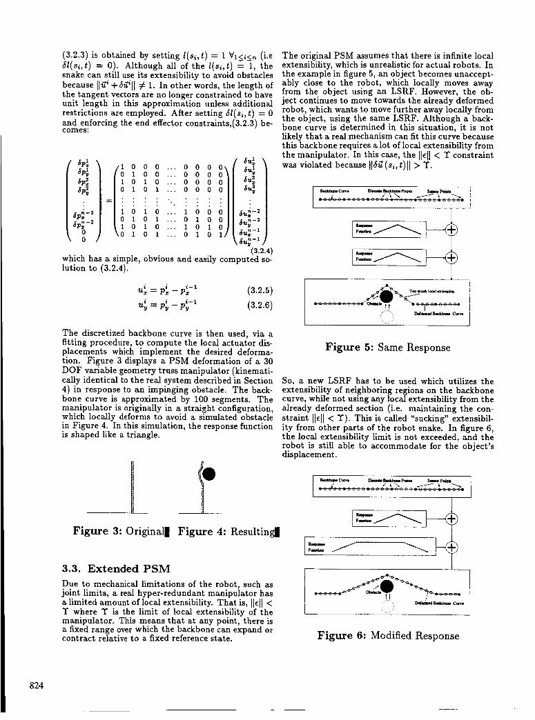
The original PSM assumes that there is infinite localextensibility, which is unrealistic for actual robots. Inthe example in figure 5, an object becomes unaccept-ably close to the robot, which locally moves awayfrom the object using an LSRF. However, the ob-ject continues to move towards the already deformedrobot, which wants to move further away locally fromthe object, using the same LSRF. Although a back-bone curve is determined in this situation, it is notlikely that a real mechanism can fit this curve becausethis backbone requires a lot of local extensibility fromthe manipulator. In this case, the IH]< T constraintwas violated because 116g(si, t)I I > T.
p \
_dl laml _l_mlkm
DarrA_l _ C_
Figure 5: Same Response
So, a new LSRF has to be used which utilizes theextensibility of neighboring regions on the backbonecurve, while not using any local extensibility from thealready deformed section (i.e. maintaining the con-straint Ilel] < T). This is called "sucking" extensibil-ity from other parts of the robot snake. In figure 6,the local extensibility limit is not exceeded, and therobot is still able to accommodate for the object'sdisplacement.
FI
-)
-)
Figure 6: Modified Response
824
-~ s w c um10n2 YYE CAGE
R6.I #-.RnMLuzd~ ~- ___ _-
4. Experimental Setup - r o w s - __ . Y)EhPo.n+y I T - ~-
To prove the feasibility of the proposed algorithms, a distributed sensor system was developed for the 30 degree-of-freedom hyper-redundant robot system de- -_ __ - _- scribed in [ChB92b]. Figure 7 shows the structure of this testbed. This section describes the test bed structure in detail.
__ U x h - ! w.rrTmm -Pu.llcLPon_ > ___- ~- 1; I - h r 1 O - A ‘.ria
4=-= - h n & -~ - - - ~ ~ -_ c”.Bn
9- 30 DOF Ilm Rdundml b1.rn.d.u~- -
The hyper-redundant manipulator is a modular Vari- able Geometry Truss design [Ch]. The 30 degree-of- freedom (DOF) planar robot consists of ten modules (also called bays) of 3 DOF each (Fig. 7). Each DOF consists of a D.C. servo motor which drives a lead screw. Each lead screw is instrumented with a lin- ear potentiometer. The real time system controller is based on a VME-bus multiprocessing computer, cur- rently consisting of two Heurikon (68030 and 68020) single board processors, and the VxWorks real time operating system. One processor is dedicated to the closed loop feedback control of the actuator positions. The other processor is dedicated to processing of sen- sor data and real time computation of the PSM algo- rithms. To enable flexible, modular, and easily expandable experimentation with sensor based planning, a novel 34 wire “Sensor Bus” architecture was developed for the sensor system. One end of the sensor bus is con- nected to the PSM processor via a parallel port. The sensor bus consists of an eight bit outgoing data path, a four bit status line, a two bit strobe and one inter- rupt request line. The data path and the two strobe lines enable the CPU to access up to 256 sensors and to send eight bits of information to the sensor pe- ripherals for possible sensor control purposes. The interrupt request line is connected to the hardware counter on the CPU board so that accurate timing measurements can be made in real time. Sensors can be added to the system via “Sensor In- terface Modules.” This module decodes the sensor bus address and generates signals to control sensors. Up to two ultrasonic sensor modules and six sets of sensors which produce data with 4 bit (or less) quan- tization can be controlled. Currently, only four in- frared sensors per board are present, though up to eight infrared sensors and eight mechanical switchs can be directly connected. The sensor interface mod- ule circuitry is mounted on a printed circuit board which is 15cm by 12cm in size. Fig. 8 shows a photo- graph of the sensor interface module. The sensor bus is physically connected in the bottom of the module in a daisy-chain fashion. In the figure, two ultrasonic transducers are shown above the module. . Also the infrared proximity sensor is shown on the side of the module.
4.2. Sensors Currently, the robot has two types of sensors: in- frared (IR) and ultrasonic (US). There are five sets of two US sensors. Each set is rigidly attached to alter-
Figure 8: Sensor Interface Module
nate bays so that each sensor points outward from the backbone curve (or the centerliiie of the mechanism). An additional US sensor will be mounted at the front of the mechanism, pointing forward. Twenty IR sen- sors, again two at each the ten bays facing outward, are currently mounted on the snake. In the near fu- ture, twenty-four additional IR sensors will be added, two more at each bay, and four in front. Fig. 9 schematically shows how these sensors are distributed throughout the mechanism.
Figure 9: Sensor Arrangement
825
Electrostatic type ultrasonic sound transducers deter- mine distance by measuring the time of flight of the ultrasound pulse leaving the transducer, bouncing off an object and returning to the sensor. A 50kHz sonar wave burst is transmitted when the sonar-ranging module is triggered [Ci]. The ranging module out- put is connected to the sensor bus interrupt request line. The echo return time is computed by the CPU hardware counter. Since the sixteen bit resolution distance measurement result is read from the hard- ware counter, no result is ever sent through the sensor bus. This design greatly simplifies the hardware re- quired.
The US sensors are activated sequentially (at 16 mil- lisecond intervals) to prevent interference between sensors. These sensors are calibrated to measure dis- tances ranging from lOcm to 2.5m, with a 2% accu- racy. There is about twenty degrees of conical ambi- guity for direction, because of the transmitting beam pattern of the transducer [Ci]. In this work, it is assumed that the obstacle lies along the cone’s cen- terline, which is locally normal to the backbone curve at the point of sensor attachment.
The IR sensors yield binary proximity information- i.e., the presence or absence of the obstacle in some pre-set range. An infrared LED emits modulated in- frared light, and if an obstacle is near the robot, the IR sensor will detect the reflected light. The range of the IR system can be adjusted by setting potentiome- ters on the sensor boards. Currently, the IR system is set up to detect the presence of obstacles up to four inches away from the robot. Like the US, the loca- tion of an obstacle is not precisely known, but lies somewhere in a cone emanating from the IR sensor.
Each sensor has its own advantage. The IR sensors have a very fast response and can be sampled at ex- tremely high rates. They are thus suitable for the PSM system. The US sensors provide proportional obstacle distance, rather than binary proximity in- formation. They are thus more useful for accurate planning. However, since the US sensors are sequen- t i d y polled to prevent interference, the minimum sampling period is 176 milliseconds. The IR sensors are sequentially polled in a similar fashion, but at a significantly higher rate. To maximize the use of both types of sensors, the sensor interface module is designed to operate both US and IR sensors simulta- neously in different intervals.
4.3. Remote Operation Console The real time computers are connected to Sun work- stations via the ethernet. Via software sockets, infor- mation can be transferred through the ethernet be- tween the real time computer running VxWorks and the Sun workstations running Unix. C programs and many software packages, such as Matlab, are able to directly communicate with the real time computers via the sockets. Therefore, these programs can con- trol the snake. The FSM and higher levels of control are implemented on the SUN workstation.
Experimental robot control programs are developed
,& i ! Figure 10: Infrared Sensor
in a combination of C and Matlab. Via an X-Window interface, these programs graphically display and con- tinually update the robot’s configuration and sensor measurements. Fig.11 shows the X-Window opera- tion console window. In addition, many motion plan- ning and sensing commands can be executed using a graphical menu interface. End-effector via points of a hyper-redundant trajectory can be specified by a mouse, and the trajectory is then executed by the real-time system.
In addition to graphically depicting the current con- figuration of the manipulator, this system displays US and IR sensor measurements. The solid cones emanating from the manipulator represent US sen- sor data. In this representation scheme, the closet point t o an obstacle in the sensor beam pattern lies somewhere on the distal arc of the cone. The dashed arcs much closer to the mechanism indicate that the IR sensors have detected nearby obstacles at these locations.
I t \\
Figure 11: Operation Console
826
5. Results The PSM algorithms described in Section 3.2 and 3.3 have been implemented on our hyper-redundant robot test-bed. Photographs of two experiments are shown below. In the first experiment, the backbone curve, dictated by some high level planner, was a straight line. Two obstacles were moved into an un- acceptably close proximity (about lOcm or 4in) to the mechanism, and the manipulator locally deformed away from each obstacle while maintaining constant end-effector position. Truthfully, the end-effector was displaced slightly from its original position (less than a 1 inch displacement over a distance of -16 feet). The current implementation of the discrete approx- imation algorithm employs only IR sensors, because there are many more IR sensor distributed alonn the snak
ro r
:e. See figure.~2. ...
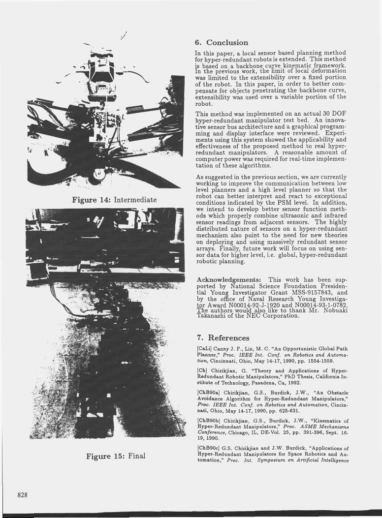
In the next experiment, again, the backbone curves starts off as a straight line. See figure 13. One obsta- cle was moved unacceptably close to the robot which resulted in the mechanism moving, as it did in the first experiment. See figure 14. Then, the object was moved sufficiently close to the deformed robot, pass- ing through the original backbone curve, and the ma- nipulator still deformed away. See figure 15. Such a large local deformation would not have been possible with the original PSM.
Th second experiment showed the local shape modifi- cation capability of the new PSM algorithm proposed in this paper. In real time, the old PSM reliably works, when the actuators in the section of the robot that is deforming are not near their joint limits. In such a case, the new PSM is the same as the old PSM. As actuators' limits are approached, local deforma- tion may become infeasible, and this is where the new PSM becomes useful. The new planner uses extensi- bility from neighboring actuator displacements along the manipulator so, the robot can still locally deform. However, once all the actuators reach there limit, i.e. all the extensibility is used up, the robot has to report to a higher level planner in order to accommodate for all the constraints in .the environment. This ability is currently being implemented in our system.
Y b r
Figure 12: First Experiment Figure 13: Second Experiment
827
Figure 14: Intermediate
Figure 15: Final
6. Conclusion In this paper, a local sensor based planning method for hyper-redundant robots is extended. This method is based on a backbone curve kinematic framework. In the previous work, the limit of local deformation was limited to the extensibility over a fixed portion of the robot. In this paper, in order to better com- pensate for objects penetrating the backbone curve, extensibility was used over a variable portion of the robot. This method was implemented on an actual 30 DOF hyper-redundant manipulator test bed. An innova- tive sensor bus architecture and a graphical program- ming and display interface were reviewed. Experi- ments using this system showed the applicability and effectiveness of the proposed method to real hyper- redundant manipulators. A reasonable amount of computer power was required for real-time implemen- tation of these algorithms.
As suggested in the previous section, we are currently working to improve the communication between low level planners and a high level planner so that the robot can better interpret and react to exceptional conditions indicated by the PSM level. In addition, we intend to develop better sensor function meth- ods which properly combine ultrasonic and infrared sensor readings from adjacent sensors. The highly distributed nature of sensors on a hyper-redundant mechanism also point to the need for new theories on deploying and using massively redundant sensor arrays. Finally, future work will focus on using sen- sor data for higher level, i.e. global, hyper-redundant robotic planning.
Acknowledgements: This work has been sup- ported by National Science Foundation Presiden- tial Young Investigator Grant MSS-9157843, and by the office of Naval Research Young Investiga- tor Award N00014-92-J-1920 and N00014-93-1-0782. The authors would also like to thank Mr. Nobuaki Takanashi of the NEC Corporation.
7. References [CaLi] Canny J. F., Lin, M. C. “An Opportunistic Global Path Planner,“ PTOC. IEEE Int. Conf. on Robotics and Automa- tion, Cincinnati, Ohio, May 14-17, 1990, pp. 1554-1559.
[Ch] Chirikjian, G. “Theory and Applications of Hyper- Redundant Robotic Manipulators,” PhD Thesis, California In- stitute of Technology, Pasadena, ca, 1992.
[ChBgOa] Chirikjian, G.S., Burdick, J.W., “An Obstacle Avoidance Algorithm for Hyper-Redundant Manipulators,” Pmc. IEEE Znt. Conf. on Robotics and Automation, Cincin- nati, Ohio, May 14-17, 1990, pp. 625-631.
[ChBSOb] Chirikjian, G.S., Burdick, J.W., “Kinematics of Hyper-Redundant Manipulators,” Pmc. ASME Mechanisms Confennce, Chicago, IL, DE-Vol. 25, PP. 391-396, Sept. 16- 19,1990.
[ChBSOc] G.S. Chirikjian and J.W. Burdick, “Applications of Hyper-Redundant Manipulators for Space Robotics and Au- tomation,” PTOC. znt. Symposium on Artificial Intelligence
I 828
and Robotics Applications to Space, Kobe, Japan, November,1990.