Page 1
Extensive investigations to-wards the development of a cu-
pola furnace process model A case study on the cupola furnace operations of Volvo
Group Trucks Operations in Skövde, Sweden
Zahra Hassan
June 2012
Master thesis
School of Industrial Engineering and Management
Department of Material Science and Engineering
Royal Institute of Technology
SE-100 44 Stockholm
Page 3
2
Master of Science Thesis MMK 2012:x MKN yyy
Extensive investigations towards the development of a cupola furnace process model
Zahra Hassan
Approved
2012-06-18
Examiner
Pär Jönsson
Supervisor
Rutger Gyllenram
Patrik Ternstedt
Commissioner
Kobolde and Partners AB
Contact person
Joel Gustavsson
Abstract
The objective of this master thesis is to evaluate the cupola furnace operations of Volvo Group Trucks
Operations in Skövde, Sweden.
This evaluation is done by developing two accurate mass and heat balance process models for the
cupola. The data used for the development of the mass and heat balances were provided by Volvo AB.
The first process model assumes that the oxygen present in the off-gas analysis is from top air leakage.
The second process model assumes that the oxygen present in the off-gas analysis is from the oxygen
injected through the tuyeres as blast air. In both process models, it has been calculated that the silicon
and manganese losses of Volvo AB’s cupola are 32 and 20 percent of the elements in the charge
respectively.
This thesis also includes exploring the possibility of increasing sulfur pickup of the cupola hot metal by
controlling the flux and slag. For the purpose of this investigation, a case study is set up to examine the
effect that decreasing limestone additions has on the properties of the slag. It is found that a decrease of
the amount of limestone added in the charged materials will result in a significant decrease in the
Page 4
3
sulfide capacity of the slag as well as the distribution of sulfur between the slag and the hot metal.
However, the viscosity of the slag also increases noticeably. Other interesting methods of increasing
the sulfur pickup of the hot metal without decreasing the viscosity of the slag are also suggested in this
thesis.
The final part of this work is a further development of Rawmatmix® software. The objective of this part
of the thesis is to compare enthalpies of different cupola slag compositions using Rawmatmix®
and
Thermocalc® in order to improve slag enthalpies and specific heat (Cp) values of Rawmatmix
®
software. The difference between the Thermocalc® and Rawmatmix
® enthalpy data is expressed as a
difference in temperature. The standard deviation of the error between Rawmatmix® enthalpy model
and Thermocalc® decreased from 64K to 32K. Finally, slag-metal equilibrium calculation is also
carried out for Volvo AB’s cupola furnace using Thermocalc®.
Page 5
4
This thesis is dedicated to my loving parents for teaching me
the importance of education
Page 6
5
Acknowledgements
Writing this master thesis would not have been possible without the support of several people.
First and foremost, I am particularly grateful to Patrik Ternstedt at Kobolde and Partners, for his pa-
tience, motivation, enthusiasm, and immense help. His guidance helped me throughout my master the-
sis. I could not have imagined having a better advisor and mentor for my master thesis.
It is also with immense gratitude that I acknowledge the support and help of my supervisors Dr Rutger
Gyllenram and Dr Joel Gustavsson at Kobolde and Partners AB whose encouragement, guidance and
support from the initial to the final level enabled me to develop an understanding of the subject.
Moreover, I owe my deepest gratitude to Mari Larsson at Volvo Group Trucks Operations for her kind
assistance in providing me with all the data from the foundry in Skövde.
Furthermore, I would like to thank Olle Westerberg for the opportunity to write this thesis at Kobolde
and Partners AB.
I would also like to express my sincere gratitude to Christer Davidsson at Volvo Group Trucks
Operations for the opportunity to work on Volvo AB’s cupola process at the foundry in Skövde,
Sweden.
Many thanks to Dr Lidong Teng and Professor Du Sichen from The Royal Institute of Technology for
helping me obtain and analyze data from ThermoSlag® software.
I am also grateful to the rest of the staff at Kobolde for their warm hospitality.
Finally, I would also like to thank my family for their love and support. I am especially grateful to my
husband, Ahmed, for his continuous support and encouragement.
Page 7
6
Table of Contents
Chapter 1 – Introduction and Overview .................................................................................................... 8
1.1 Background ..................................................................................................................................... 8
1.2 Problem description ........................................................................................................................ 8
1.3 Method and Disposition .................................................................................................................. 9
Chapter 2- LITERATURE SURVEY: Foundry Cast Iron and cupola furnace ........................................ 11
2.1 Introduction .................................................................................................................................... 11
2.2 Cast Irons ....................................................................................................................................... 11
2.2.1 Principles of the metallurgy of cast irons ............................................................................... 13
2.2.2 Types of cast irons .................................................................................................................. 17
2.3 Conventional cupola furnace operation ........................................................................................ 20
2.3.1 Construction ........................................................................................................................... 21
2.3.2 Reaction zones ....................................................................................................................... 22
2.3.3 Acidic and basic cupolas ........................................................................................................ 25
2.4 Factors affecting cupola performance ........................................................................................... 26
2.4.1 Optimum blast rate ................................................................................................................. 26
2.4.2 Optimum charge mixture selection ........................................................................................ 27
2.4.3 Trade off between coke efficiency and oxidation losses ........................................................ 28
2.5 Cupola fluxes and slags................................................................................................................. 29
2.5.1 Usual fluxes............................................................................................................................ 30
2.5.2 Sources of slag ....................................................................................................................... 30
2.5.3 Acid slag composition ............................................................................................................ 31
Chapter 3- Modeling of cupola furnace: Mass and heat balance of Volvo AB’s cupola furnace in
Skövde ..................................................................................................................................................... 33
3.1 Introduction ................................................................................................................................... 33
3.2 Mass balance ................................................................................................................................. 34
3.1.2 Mass balance calculations ...................................................................................................... 35
3.2 Standard deviation of the output hot metal ................................................................................... 39
3.3 Heat balance calculations .............................................................................................................. 40
3.4 Disscussion and conclusion .......................................................................................................... 42
Chapter 4 – Sulfur pickup of cupola hot metal: Slag viscosity and sulfide capacity analysis using
optical basicity model and Thermoslag® software .................................................................................. 45
4.1 Introduction ................................................................................................................................... 45
4.2 Thermoslag® model ...................................................................................................................... 46
4.3 Optical basicity model .................................................................................................................. 47
Page 8
7
4.4 Case study ..................................................................................................................................... 48
4.5 Discussion and conclusion ............................................................................................................ 51
Chapter 5- Slag enthalpies of Thermocalc® and Rawmatmix
®: A parameter study ............................... 53
5.1 Introduction ................................................................................................................................... 53
5.2 Thermocalc®
.................................................................................................................................. 53
5.3 Rawmatmix® ................................................................................................................................. 54
5.4 Linear regression ........................................................................................................................... 54
5.5 Parameter study ............................................................................................................................. 54
5.6 Slag-metal equilibrium calculations .............................................................................................. 57
5.7 Discussion and conclusion ............................................................................................................ 57
Chapter 6 - Conclusion ........................................................................................................................... 59
Chapter 7- Further Work ......................................................................................................................... 64
References ............................................................................................................................................... 65
Page 9
8
Chapter 1 – Introduction and Overview
1.1 Background
Cast irons are a type of ferrous alloys which have a wide range of mechanical properties which make
them applicable for use in engineering components. Cast irons are produced by casting them into a
shape instead of forming them into shape. Cast irons contain 2-4wt% carbon and 1-3wt%
silicon. Other elements are also used to control specific properties of cast irons. The wide spread use of
cast iron is due to its low cost and adaptable properties. The world cast iron production was
approximately 92 million tons in 2010. [1-5]
Cast iron is normally made by induction furnace, electrical arc furnace or cupola furnace. Despite being
one of the oldest methods of converting cold scrap metals or pig irons to molten iron, the cupola
furnace is still considered by some to be the cheapest and the most efficient method. A cupola furnace
is a vertical cylindrical shaft where hot ascending gases (produced by combustion of coke at the bottom
the furnace) come into contact with the descending melting stock. The furnace is charged at regular
intervals with some amounts of metallic charge, coke and limestone. The metallic charges represent 70-
80% of the total product cost and have range of analyses and cost categories. [1-4, 6]
Volvo Group Trucks Operations’ foundry in Skövde, Sweden is the largest foundry in northern Europe
which produces cast irons. Half of all grey cast iron in Sweden is cast in this foundry. The foundry has
four induction furnaces and two cupola furnaces with an annual capacity of 114,234 tons of finished
cast goods in 2011. The products of this foundry mainly include cylinder blocks and cylinder heads,
brake discs, and flywheels. The foundry is also an active member in the Swedish Foundry Association,
which in turn is a member of The World Foundrymen Organization [5, 7]
1.2 Problem description
The objective of this master thesis is to evaluate the cupola furnace operations of Volvo Group Trucks
Operations in Skövde, Sweden. This evaluation should be done by developing an accurate mass and
Page 10
9
heat balance process model for it. This thesis also explores the possibility of increasing the sulfur
pickup of the cupola hot metal by controlling the flux and slag.
The final part of this work is a further development of the Rawmatmix® software developed by an
offspring company from the Royal Institute of Technology, KTH. The objective this part of the thesis is
to compare the enthalpies of different cupola slag compositions using Rawmatmix® and Thermocalc
®
in order to improve the slag enthalpies and specific heats (Cp) values of Rawmatmix® software.
1.3 Method and Disposition
Due to reasons of confidentiality, this thesis is split into two parts; the official part comprising of eight
chapters and an appendix presenting sensitive and confidential data of Volvo Group Trucks Operations.
Chapter 2 is a literature survey on cast irons and the melting operations of foundry cast irons. The cu-
pola furnace in foundry operations is also studied in this chapter. Selection of the optimum metallic
charge proportions which meets the required melt analysis at the minimum cost is also examined.
The information presented in the literature survey is based on research from secondary sources such as
renowned books, published articles and reliable websites. Due to time limitations, the primary refer-
ence sources were not traced back.
In chapter 3, a mass balance is set up for Volvo AB’s cupola furnace which produces gray cast irons.
The data of the mass balance is then used to develop a heat balance. In the heat balance, the total heat
content of the input and output materials are evaluated in order to calculate the heat losses.
Chapter 4 includes a research which explores the possibility of increasing sulfur pickup by controlling
the flux and slag composition.
In chapter 5, the difference in cupola slag enthalpies of 52 cases using Thermocalc®
and Rawmatmix®
are compared. Linear regression using the least square approach is then used to approximate more ac-
curate slag enthalpies and specific heats (Cp) for Rawmatmix®. In this chapter, slag-metal equilibrium
calculations are carried out for Volvo Group Trucks Operations’ cupola furnace using Thermocalc®
.
Page 11
10
The appendix which is not part of the official copy of this thesis contains sensitive data of Volvo AB’s
cupola in Skövde.
Page 12
11
Chapter 2- LITERATURE SURVEY: Foundry
Cast Iron and cupola furnace
2.1 Introduction
A foundry can be defined as a factory which produces metal castings. The general processes involved
in foundries include melting the metals, pouring the metal in a mold, and removing the mold material.
Aluminium and cast iron are among the most common metals processed in foundries. However, other
metals such as magnesium, steel, zinc, copper and tin are also produced in foundries [1-2]. In this
chapter, a literature survey has been carried out on cast irons and the melting operations of foundry cast
irons. The cupola furnace in foundry operations has been studied. Selection of the optimum metallic
charge proportions which meets the required melt analysis at the minimum cost has also been
examined.
2.2 Cast Irons
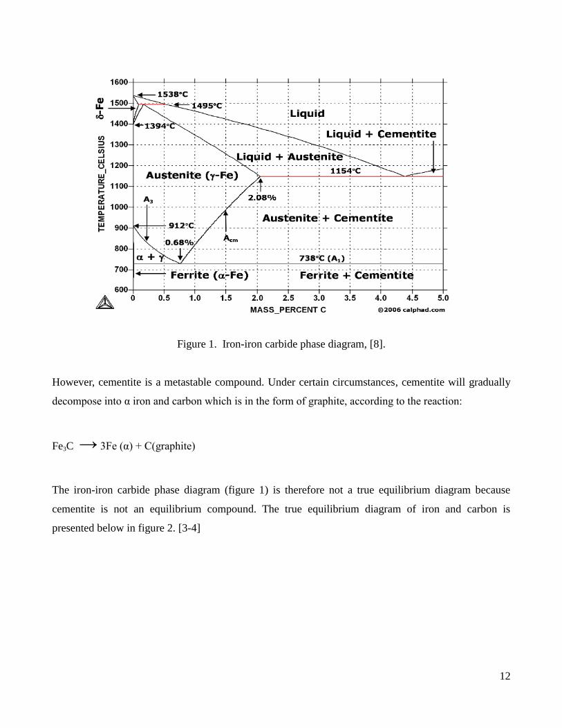
Cast irons are a type of ferrous alloys which contain carbon contents above 2.14wt%. However, most
cast irons contain between 3.0 and 4.5wt% C and other alloying elements. Figure 1 below shows the
iron-iron carbide phase diagram. From the phase diagram, it is evident that alloys within this
composition range are completely liquid at temperatures between 1150 and 1300oC. This is
considerably lower than for steels. As the cast iron alloy is cooled (at normal cooling rates), below
1147oC the intermediate iron carbide compound known as cementite coexists with the austenite phase.
[3-4]
Page 13
12
Figure 1. Iron-iron carbide phase diagram, [8].
However, cementite is a metastable compound. Under certain circumstances, cementite will gradually
decompose into α iron and carbon which is in the form of graphite, according to the reaction:
Fe3C → 3Fe (α) + C(graphite)
The iron-iron carbide phase diagram (figure 1) is therefore not a true equilibrium diagram because
cementite is not an equilibrium compound. The true equilibrium diagram of iron and carbon is
presented below in figure 2. [3-4]
Page 14
13
Figure 2. Iron-carbon phase diagram, [9].
Depending mainly on the composition, cooling rate and melt treatment, cast iron can solidify according
to the iron-graphite system or the thermodynamically metastable Fe-Fe3C system. For most cast irons,
the carbon exists as graphite. [3-4]
2.2.1 Principles of the metallurgy of cast irons
The aim of the cast iron metallurgist is to design a process which will produce the micro-structure that
will yield the required mechanical properties. This requires knowledge of all the main factors which
will affect the microstructure of the cast iron as well as knowledge of the structure-property correlation
of cast irons. The main factors which influence the microstructure of cast irons are: [3-4]
- chemical composition
- cooling rate
- liquid treatment
- heat treatment
Page 15
14
Chemical composition
The chemical composition of cast irons affects the shape and distribution of graphite and the required
matrix. Table 1 shows the composition range for typical unalloyed common cast irons.
Silicon and carbon in cast irons promote graphite formation. Silicon promotes graphite formation in
concentrations above 1wt%. The effect that silicon and carbon have on cast irons can be combined into
a single factor called the carbon equivalent, CE. [3-4]
CE: %C +1/3%Si
The CE of cast iron is a description of how close a given analysis is to that of the eutectic composition.
Since the CE is a thermodynamic parameter which depends on the chemical composition of the alloy,
other equations indicating the CE of cast irons have also been proposed. [10]
Although an increase in carbon and silicon contents increases the graphitization potential, the strength
is undesirably affected (see fig 3). This is because a higher carbon equivalent promotes a ferritic matrix
and a coarsening of pearlite. The approximate silicon content of most cast irons is about 2wt%. [3-4]
Figure 3. Influence of carbon equivalent on the tensile strength of gray iron. [3]
The manganese content depends on the desired matrix of the cast iron. Manganese is a strong pearlite
promoter. It can be as low as 0.1% when ferritic irons are desired and as high as 1.2% when pearlitic
irons are required. [3-4]
Page 16
15
Phosphorus and sulfur are always present in the composition of most cast irons. They can be as high
0,15wt% for low quality iron and are significantly less for high-quality iron. [3-4] Sulfur, when added,
forms the harmful iron sulfide compound, which prevents the formation of graphite and increases the
hardness. However, when manganese is added, MnS forms which acts as a nuclei for flake graphite
formation. According to stoichiometry, the required ratio between manganese and sulfur for FeS-free
structure is a follows: [3-4]
%Mn=1.7(%S)
Table 1. The composition range for typical unalloyed common cast irons [3]
A pile of iron scrap often contains many chemical elements. Since most of these chemical elements are
present in small amounts, they are often not harmful to the cast irons. Among the chemical elements
which usually are not harmful in small amounts are nickel, chromium, cobalt, copper, molybdenum,
titanium and vanadium. [6]
However, cast irons have a low tolerance for some of the chemicals present in the scrap. [6]
Table 2 below summarizes the effect some of these chemicals have on the properties of cast irons.
Page 17
16
Table 2. The effect certain chemicals have on the properties of cast irons. [3, 11]
Element Its effect on the properties of cast irons
Aluminum At levels above 0.005% aluminum promotes pinhole defects. In larger amounts, it renders
the metal sluggish in pouring and causes the formation of dross, resulting in surface defects
in the castings.
Antimony Additions of 0.01% reduces the amount of ferrite sometimes found adjacent to cored sur-
face. It is harmful to the static and impact properties of cast iron.
Bismuth Concentration of 0.02% promotes undesirable graphite types which decrease tensile proper-
ties.
Tellurium At concentrations of 0.001%, it is a strong carbide former.
Hydrogen 0,0004% produces subsurface pinholes.
Lead Produces Widmanstätten graphite which makes the cast goods very brittle. Lead has also
been reported to cause extreme gas porosity in iron castings.
Cooling rate
The cooling rate, like the chemical composition, can significantly influence the distribution of graphite
and the required matrix. An increase in the cooling rate will
- Refine the size of the graphite and the matrix structure, which will result in an increased
strength and hardness.
- Increase the chilling tendency; this will result in higher hardness, but will decrease the
toughness.
The composition of the cast iron must be modified in such a way that it will provide the correct
graphitization potential for a certain cooling rate. [3-4]
Liquid treatment
Liquid treatment of cast irons is also known as inoculations. It can dramatically change the nucleation
and growth conditions of graphite during solidification. This makes it very important in the processing
of this alloy. It is also recognized that two irons with the same apparent compositions can have
dramatically different microstructures and properties if one is inoculated and the other is not. Liquid
Page 18
17
treatment consists of small additions of minor elements such as FeSi containing other trace elements.
[3-4]
The main inoculations effects are:
- A finer structure with a consequent increase in strength
- An increased graphitization potential and the graphite shape changes to a uniform distribution
with a random orientation [3-4]
Heat treatment
In gray irons, usual heat treatments include stress relieving or annealing to decrease the hardness.
Although heat treatment has no influence on the graphite shape and size, it can significantly change the
matrix structure and thus the mechanical properties of gray cast irons. However, a low amount of the
gray iron produced is heat treated. [3-4]
In ductile irons, usual heat treatments include stress relieving, annealing to produce a ferritic matrix or
normalizing to produce a pearlitic matrix. [3-4] Heat treatment is not a usual practice for compacted
graphite cast iron. [3-4]
In malleable irons, heat treatment determines the final structure. The heat treatment has two basic steps.
During the first step, the iron carbide is decomposed into austenite and graphite. The austenite is then
transformed into pearlite, ferrite, or a mixture of the two in the second step. [3-4]
2.2.2 Types of cast irons
Cast irons can be divided into five main types
• Gray cast iron
• Ductile (or nodular ) cast iron
• White cast iron
• Malleable cast iron
• Compacted graphite cast iron (CGI)
Page 19
18
Gray cast iron
The carbon content in gray cast iron varies between 2.5 and 4 wt%. The silicon content of gray cast
varies between 1.0 and 3.0wt%. Other elements present include manganese, phosphorus, and sulfur.
The graphite in gray cast iron exists in the form of flakes, which are surrounded by an α-ferrite or a
pearlite matrix. A pearlite matrix forms if the silicon amounts are low or if the cooling rate is high. This
is because the complete dissociation of cementite to form graphite is hindered. Due to the graphite
flakes, a fractured surface of gray cast iron has a gray appearance, hence its name. [3-4]
Since the tips of the graphite flakes are sharp and pointed, they may serve as points of stress
concentration when an external tensile stress is applied. Therefore gray iron is relatively weak and
brittle in tension as a consequence of its microstructure. [3-4]
However, strength and ductility are much higher under compressive loads. Also, gray cast irons are
very effective in damping vibrational energy. They are frequently used for base structures for machines
and heavy equipment which are exposed to vibrations. Gray irons also have a high resistance to wear.
Furthermore, they have a high fluidity at casting temperatures, which permits casting of pieces having
complex shapes. Finally, and perhaps most importantly, gray cast irons are among the least expensive
of all metallic materials. [3-4]
Ductile (or nodular) cast iron
Ductile cast iron (also known as nodular) is produced by adding a small amount of magnesium and/or
cerium to the gray iron before casting. It has a distinctly different microstructure and thus different
mechanical properties. Graphite is present as nodules or spheres like particles instead of flakes. The
matrix phase surrounding these particles is either pearlite or ferrite, depending on heat treatment.
Ductile cast irons are stronger and much more ductile than gray iron. In fact, ductile iron has
mechanical properties close to those of steel. These alloys are often used in valves, pump bodies, crank
shafts, gears, and other automotive and machine components. [3-4]
White cast iron
White cast irons are produced by rapidly cooling cast irons containing low-silicon amounts (containing
less than 1.0 wt% Si). Therefore, most of the carbon exists as cementite instead of graphite. White cast
Page 20
19
iron usually has high amounts of carbide stabilizing elements like Cr. A fractured surface of this alloy
has a white appearance, and therefore it is called white cast iron. White cast iron is extremely hard but
also very brittle as a result of the large amounts of the cementite phase present. It’s used as rollers in
rolling mills. However, generally white iron is used as an intermediary in the production of another cast
iron; malleable cast iron. [3-4]
Malleable cast iron
Malleable cast iron is produced by heating white iron at temperatures between 800 and 900oC in a
neutral atmosphere (to prevent oxidation). This causes the decomposition of the cementite to graphite.
The graphite in malleable cast iron exists in the form of clusters or rosettes surrounded by a ferritic or
pearlitic matrix, again depending on the cooling rates. These alloys have relatively high strength and an
appreciable ductility or malleability. They are used in connecting rods, transmission gears and
differential cases for the automotive industry. [3-4]
Compacted graphite cast iron (CGI)
In CGIs, the carbon content is between 3.1 and 4.0wt% whereas the silicon content ranges between 1.7
and 3.0 wt%. The carbon in CGIs exists as graphite. The graphite has a vermicular (worm-like) shape.
Magnesium and/or cerium is also added, but in lower concentrations than for ductile iron. The
chemistry of CGIs is more complex than for the other types of cast irons. This is because the
compositions of magnesium, cerium, and other additives must be controlled in order to produce the
right microstructure that consists of the worm-like graphite particles, while at the same time limiting
the degree of graphite nodularity and preventing the formation of graphite flakes. The matrix phase will
be pearlite and/or ferrite depending on the heat treatment. CGIs with ferritic matrices have lower
strengths and higher ductilities than those with pearlitic matrices. Tensile and yield strengths and higher
ductilities than those with pearlitic matrices. [4]
The tensile and yield strengths for compacted graphite irons are similar to the values for ductile and
malleable irons. According to Callister [4], CGIs have overall higher thermal conductivities, good
resistance to thermal shock and lower oxidation at elevated temperatures compared to the other cast
Page 21
20
iron types. It is also interesting to note that Karlebo Gjuteriteknisk handbook [43] shows that CGIs have
lower thermal conductivities than gray irons at 573 K.
Compacted graphite cast irons are used in diesel engine blocks, exhaust manifolds, gearbox housings,
brake discs for high speed trains, and flywheels. [3-4]
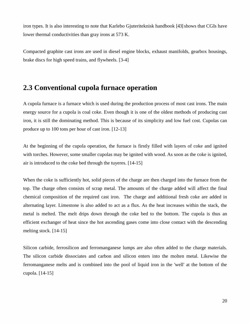
2.3 Conventional cupola furnace operation
A cupola furnace is a furnace which is used during the production process of most cast irons. The main
energy source for a cupola is coal coke. Even though it is one of the oldest methods of producing cast
iron, it is still the dominating method. This is because of its simplicity and low fuel cost. Cupolas can
produce up to 100 tons per hour of cast iron. [12-13]
At the beginning of the cupola operation, the furnace is firstly filled with layers of coke and ignited
with torches. However, some smaller cupolas may be ignited with wood. As soon as the coke is ignited,
air is introduced to the coke bed through the tuyeres. [14-15]
When the coke is sufficiently hot, solid pieces of the charge are then charged into the furnace from the
top. The charge often consists of scrap metal. The amounts of the charge added will affect the final
chemical composition of the required cast iron. The charge and additional fresh coke are added in
alternating layer. Limestone is also added to act as a flux. As the heat increases within the stack, the
metal is melted. The melt drips down through the coke bed to the bottom. The cupola is thus an
efficient exchanger of heat since the hot ascending gases come into close contact with the descending
melting stock. [14-15]
Silicon carbide, ferrosilicon and ferromanganese lumps are also often added to the charge materials.
The silicon carbide dissociates and carbon and silicon enters into the molten metal. Likewise the
ferromanganese melts and is combined into the pool of liquid iron in the 'well' at the bottom of the
cupola. [14-15]
Page 22
21
During the operation, the cupola operator observes the amount of iron rising at the bottom of the
cupola. The cupola operator opens the tap hole to let the metal flow into a ladle, when the metal level
is sufficiently high. When enough metal is drawn off, the tap hole is plugged with a refractory plug
made of clay. [14-15]
2.3.1 Construction
A conventional cupola is a vertical cylindrical steel shell with its interior lined with heat resisting
refractory (Figure 4). At the bottom of the cupola, there are drop doors. The drop doors are closed so
that a proper sand bed can be prepared. The sand bed provides an essential refractory bottom for both
the molten metal and the coke. Directly above the sand bed is the metal tapping hole. The metal tapping
hole is closed with clay (known as a bot) unless the molten metal is ready for tapping. The slag hole is
located at an opposite position to the metal tap hole. The slag is tapped from this position. [14-15]
The wind box which is above the slag hole is connected to air blowers which provide the required air at
a given pressure and temperature. The air is introduced to the cupola through the tuyeres. Just above
the charging platform is the charging door. The charge is added to the cupola through the charging door.
[14-15]
Figure 4. Illustration of a typical conventional cupola [15]
Page 23
22
2.3.2 Reaction zones
The cupola has three main zones where various chemical reactions take place. The lengths of the zones
are not well defined as the reactions often take place over varying distances. These distances are
determined by the existing chemical and physical conditions in the cupola. [16, 17]
The three main reaction zones in a cupola are (see fig 5); [16, 17]
1. Below the zone of melting.
2. In the zone of melting
3. Above the zone of melting
Below the zone of melting
This zone consists of two main reaction regions.
(1) Region 1: Tuyere region. This region is just below the melt zone and it is the region where air is
introduced through the tuyeres. [16, 17]
(2) Region 2: Coke bed region. This region consists of coke through which iron and slag drops fall.
There is no gas flow in this region or in the region below it. [16, 17]
Reactions in the tuyeres region
Air which is often oxygen-enriched reacts with carbon from coke to produce CO2 gas
Ccoke + O2 = CO2
The rate of the above combustion reaction is controlled by the size of the coke, and the oxygen,
temperature and velocity of the gas. Since the above reaction is exothermic, it is the major heat source
in the cupola. The combustion reaction is the sum of two series reactions. Firstly, oxygen diffuses to
the coke surface where it reacts to form CO. As the CO diffuses away from the coke it reacts with the
remaining oxygen to form CO2.
[16, 17]
Ccoke + 1/2O2= CO
CO + 1/2O2 =CO2
Page 24
23
Due to the high temperatures that exist in the combustion region, the CO2 from the combustion reaction
will react with coke to form CO once the surrounding oxygen has been used. The rate of this reaction is
controlled by the concentration of CO2, gas velocity, and the size, porosity and reactivity of coke. This
reaction is endothermic and is also known as the Boudouard reaction. [16, 17]
Ccoke + CO2 = 2CO
During the Boudouards reaction, some CO2 diffuses into the porous coke where it reacts with carbon.
However, some CO2 diffuses to the coke surface where it reacts with coke. This is the main reaction
above 1000oC. Below 1000
oC the pore reaction controls the rate. The rate of both reactions drops
significantly as the temperature decreases. [16, 17]
As the Boudouards reaction consumes energy produced to heat the metal, the foundry attempts to
minimize it. Foundries currently use large coke sizes to minimize Boudouards reaction. [16, 17]
As the carbon in coke is consumed the remaining sulfur in the coke reacts with air to produce SO2.
Some of the SO2 reacts with iron while the remaining SO2 escapes the cupola in the outgoing exhaust
gas. [16, 17]
Scoke + O2 = SO2
Another important reaction is the endothermic reaction of coke and CO with water in the incoming
blast [16, 17]:
Ccoke + H2O = CO + H2
H2O + CO = CO2 + H2
Because of the high oxidation potential of the gasses in the region just above the tuyeres, alloy
oxidation takes place. [16, 17]
Si + 2CO2 = SiO2 + 2CO
Mn + CO2 = MnO + CO
Reactions in the coke bed region
This region contains only coke, iron and slag drops. In this region the iron drops pickup carbon.
3Fe + C → Fe3C.
Page 25
24
Also, iron which has been oxidized above the tuyeres region is reduced in the coke bed region. [16, 17]
In the zone of melting.
In this zone, melting of scrap and alloys takes place. These processes are endothermic. [16, 17]
Fesolid = Feliquid
FeSisolid = FeSiliquid
The area of the melting zone depends on the thickness and melting point of the charged scrap. Due to
their lower melting points, cast iron and ferrosilicon melt higher in the cupola compared to steel. [16,
17]
Reduction of FeO by alloys takes place in this zone. The total FeO content in this region comes from
rust on the charge material and oxidized iron in the zone above the melting zone. [16, 17]
FeO + Ciron = CO + Fe (endothermic)
FeO + ½ Siiron = ½ SiO2 + Fe (exothermic)
The amount of Si lost due to reaction with FeO may depend on the oxygen potential of the furnace.
Furthermore, sufficient carbon content picked by the molten metal takes place in this zone. [16, 17]
3Fe + 2CO → Fe3C + CO2
Above the zone of melting
This zone consists of a number of alternate layers of coke bed, flux and metal charge. In this zone,
descending charges are preheated with the ascending hot exhaust gases from room temperature to about
1090°C. Moreover, the metal charge in solid form picks up some sulfur in this zone. [16, 17]
Page 26
25
Figure 5. Idealized diagram representing reaction zones in the cupola furnace. [6]
2.3.3 Acidic and basic cupolas
There are two types of cupolas (basic or acidic) depending on the type of refractory lining used. Basic
cupolas are often lined with magnesia bricks or dolomite plaster. A basic cupola can reduce the sulfur
content in the melt to approximately 0.005%. Carbon pick up by the melt in a basic cupola is also high-
er. Acid cupolas often have a fire clay brick lining and are also easier and cheaper to operate. Acid cu-
polas are the usual type of cupolas used for general production of cast iron. Table 3 summarizes the
advantages and disadvantages of basic and acidic cupolas. [18]
Page 27
26
Table 3. Advantages and disadvantages of basic and acidic cupolas. [6, 18]
Basic cupola Acidic cupola
Metal analysis is more difficult to control Metal analysis is easier to control
Silicon losses are high Silicon losses are lower
Refractory costs are high Refractory costs are lower
Fluxing material costs are higher Fluxing material costs are lower
Lower sulfur levels are easily obtainable Cannot obtain very low amounts of sulfur
Higher carbon pickup Lower carbon pickup
Ability to use low cost (poor quality) charging
2.4 Factors affecting cupola performance
A cupola furnace should aim to provide molten metal with the desired chemistry at a required rate and
at the desired temperature. The main factors which affect the performance of the furnace are blast rate,
the coke to metal ratio and a correct charge mixture selection. [6, 19]
2.4.1 Optimum blast rate
When a cupola is operated at an optimum blast rate, it will melt the charged material efficiently and
economically. Figure 6 shows the relationship between the blast rate and the metal temperature at a
given metal: coke ratio. This graph illustrates that as the blast rate is increased, the tapping temperature
of the metal increases until a maximum value is reached. Beyond this maximum value, a further in-
crease in the blast rate causes the temperature to decrease. Practically, the optimum blast rate varies
with the metal-coke ratio and the nature of the materials melted. Experimentally and practically, it has
been obtained that this optimum blast rate is between 110-120m3/min per square meter of cupola cross-
sectional area at the tuyeres. The blast rate can be controlled accurately by using an air-flow meter. [19]
Page 28
27
Figure 6. Effect of blast rate on metal temperature at constant coke charge, [19].
For any given cupola, the relationships between the blast rate, coke charge, the melting rate and the
metal temperature are plotted as net diagrams. These diagrams for 0.9, 1.1, 1.2, 1.4, 1.5, 1.7 and 1.8
meter cupolas can be obtained from the American Foundrymen's society text book, [6, 16-17, 19-22].
2.4.2 Optimum charge mixture selection
The metallic charges of the cupola often have different compositions. They represent about 70-80% of
the total product cost. Therefore, the selection of the optimum metallic charge amounts, which meet the
required melt analysis at the minimum cost, is an important process step in the operations of the cupola.
[6, 16-17, 19-22].
The two main factors which effect the selection of optimum metallic charge proportions are:
– knowledge of the raw materials entering the cupola (coke, flux, scrap and iron ore composi-
tions)
– knowledge of how the cupola operations affect the chemistry of the charge
The compositions of coke, flux, internal scrap and iron ore are often fairly well known. However, ac-
quiring good knowledge of the chemical compositions of purchased scrap is often difficult. This diffi-
culty can be solved by requesting uniformity assurance from the supplier or by careful self-inspection
of the scrap. [6, 16-17, 19-22].
Knowledge of how the cupola operations affect the chemistry of the charge is essentially knowledge of
the losses or gains of the elements melted in the cupola. Approximate losses or gains of elements in the
melting of a good cupola can be obtained from text books or industrial data. However, it is important to
note that these data may only be used as a very rough guide for mixture makings. For accurate calcula-
Page 29
28
tions, data of losses and gains of elements of the particular cupola under consideration should be used.
This data can be calculated by studying the input and output compositions of the cupola under consid-
eration. [6, 16-17, 19-22].
The most important elements to consider in the charge calculations are carbon, silicon, manganese and
sulfur. Some amount of carbon is picked up from the coke depending on temperature and time of con-
tact. Carbon pick up of the order of 0,15% is a reasonable approximation. Sulfur is also often picked up
from the coke. Although the sulfur pickup depends on the sulfur content of the coke, a reasonable ap-
proximation could be 40 to 60%. Silicon is often oxidized in the cupola. Silicon loss of 10% of the
total silicon content in the charge is considered normal under good operations. However, under bad
cupola operations, silicon losses may be as high as 30%. Manganese is also often oxidized. Manganese
loss is often in the order of 10 -20%. [6, 16-17, 19-22].
The method of calculating the cupola charge is as follows [6, 16-17, 19-22].
1. The average composition of the ingoing material which is based on the respective weights
/percentages and chemical compositions of the different input constituents needs to be obtained.
2. Approximate loss or gains data is used to add or subtract the gains or losses.
The results obtained at this point give a close estimate of the percentages of the elements in the output
material. However, careful attention should be given to separation and weighing of different
types/grades of the input material and the removal of nonmetallic materials such as sand from the scrap
during storage and handling. Failure to do so with care will waste the efforts made to calculate the cu-
pola charges. [6, 16-17, 19-22].
2.4.3 Trade off between coke efficiency and oxidation losses
A higher percentage of carbon dioxide in the off gases analysis means that there is a more complete
combustion of the coke, and release of a larger amount of the potential heat in the fuel. Thus, increasing
the carbon dioxide in the off gases analysis will decrease the cost of coke per ton of iron melted. Only
from the standpoint of coke economy, it is obvious that certain savings will result from more complete
combustion. However, as the efficiency of the of the combustion increases, the oxygen potential in the
Page 30
29
furnace also increases. This leads to an increased amount of silicon and manganese oxidation losses to
the slag phase. Therefore, maximum economy is not achieved with maximum efficiency of combustion
but a balance between combustion efficiency and losses due to oxidation. [6] (figure 7)
Figure 7. Trade off between coke efficiency and oxidation losses
2.5 Cupola fluxes and slags
During the cupola melting process, some residue amounts of non-metallic material accumulates which
is known as slag. The cupola slag typically consists of coke ash, oxide products, fluxed refractory lin-
ing and some dirt. The slag that is naturally formed is very viscous due to its high concentrations of
acid constituents like silicon oxide. Without some adjustment to the slag, it will clog up the interstitial
spaces in the coke and build up a bridge in the zones cooled by the air from the tuyeres. Basic flux ma-
terials such as limestone or dolomite are needed to liquefy the slag in order to assist its removal from
the cupola. A flux can be defined as a substance which reacts with slag to increase its fluidity and refin-
ing properties by lowering its fusion point. An addition of excessive amounts of basic flux is harmful to
the lining of common acid cupolas as a more basic slag seriously attacks acid refractories. When the
cupola operates with basic slag, basic refractory is necessary. [6]
Page 31
30
2.5.1 Usual fluxes
Natural rock limestone (CaCO3) is the most common flux for cupola slags. It is calcined to lime (CaO)
as it descends towards the melting zone. A fluid of calcium-silicate slag forms when the basic calcium
oxide reacts with the gummy acid silicon oxide. This appropriately balanced fluid of calcium-silicate
slag will drip easily through the coke interstices, accumulate in the well, and flow easily from the cupo-
la. [6]
There are a number of more active basic materials that are sometimes used as additional fluxes. These
include sodium carbonate, calcium fluoride and calcium carbide.
Sodium carbonate (Na2CO3) can be added in the form of lumps, fused pigs, or pellets and will add a
further fluidity to the slag. Sodium carbonate is also used as a slag treatment as its relatively low melt-
ing point allows it to melt higher in the stack and to drip down over the coke, reacting with any viscous
slag. [6]
Calcium fluoride (CaF2) is known to improve slag fluidity and is also a powerful fluxing agent which
is sometimes used in small amounts along with limestone. [6]
Calcium carbide is a fluxing agent and has a lower fusion and combustion temperature which allows it
to melt and burn in the cupola bed. Its effect is to increase the melting rate, produce hotter iron and
therefore reduce the coke requirements. [6]
2.5.2 Sources of slag
There are four main sources of slag in a typical cupola operation.
The first source of slag is the coke ash. The higher the coke consumption, the higher the amount of flux
requirements. Also, higher ash content in the coke requires an increase in the flux additions. [6]
The second main source of slag is the oxidation elements of the metal. Silicon and manganese are the
main element oxidized in the metal. Iron is also occasionally oxidized but in much smaller amounts.
Page 32
31
When a cupola has higher silicon irons and/or more oxidizing conditions, higher flux additions are
needed. [6]
The third source of slag comes from refractory wear. Cupolas operating with water cooled or neutral
linings have relatively low refractory wear. Also, larger cupolas operated for long periods have a lower
refractory wear per ton of metal melted compared to smaller cupolas. When the refractory wear is high,
higher flux additions are needed. Moreover, poor refractory quality or inconsistent lining practice can
cause irregularities in the slag condition. [6]
The fourth source of slag is dirt/sand which may be included with purchased cast scrap or attached to
return scrap. This extra dirt/sand is mainly sand which requires additional flux to condition it. Changes
in the amount of sand/dirt that enters together with the scrap without some flux adjustment often causes
irregularities in the slag and slag performance problems. It is worthwhile to prevent such extra sand
from entering the cupola in order to maintain conditions promising consistent slag. [6]
2.5.3 Acid slag composition
Cupola slags consist of various oxides which are combined into solutions of silicates, and possibly
aluminates of calcium, magnesium, manganese and iron. The main compositions of acidic slag are
silicon dioxide, aluminum oxide, magnesium oxide, manganese oxide, iron oxide and sodium oxide. [6]
Silicon dioxide (SiO2) is acid in nature and is the largest constituent in acidic slags. It typically ranges
between 40 to 50% in acid slags. The sources of silicon dioxide include coke coke ash, refractory lin-
ing, oxidation of silicon from the metal and some dirt/sand. [6]
Aluminum oxide (Al2O3) is classed as neutral in nature because of its amphoteric ability to act as a
basic constituent in acidic slags. Alumina comes mainly from the coke ash and clay refractories. It gen-
erally ranges from 10 to 20 % in acidic slags. [6]
Calcium oxide (CaO) is added as limestone, and is the main basic constituent in cupola slags. It gener-
ally ranges from 25 to 35% in acidic slags. [6]
Page 33
32
Magnesium oxide (MgO) like calcium oxide behaves as a basic constituent. The MgO content is as
high as 5-20% when dolomitic limestone is used, along with 10-25 percent CaO. However, the magne-
sium oxide’s content from all sources usually runs less than 5 percent when straight limestone is used.
[6]
Iron oxide (FeO) is usually present in proportions of approximately 1-8%. The amount of iron oxide in
the slag depends on the overall balance between the oxidizing and reducing conditions in the cupola.
Factors which increase the FeO content in the slag include severe blowing, uneven charge distribution,
low amounts of coke, poor coke and higher percentages of steel. However, with a good cupola opera-
tion, the FeO content in the slag can be as low as 1%. [6]
Manganese oxide (MnO) content is usually under 5%. It comes from the manganese oxidized from the
metal. It acts as a base but its effects are generally insignificant because of its low concentrations. [6]
Sodium oxide (Na2O) is present in concentrations of up to 5% when soda fluxes are used. Since Na2O
is more basic than limestone, it has a larger effect on the fluidity of the slag. Higher final concentra-
tions of sodium oxide are difficult to achieve as Na2O sublimes at 1275oC. [6]
Page 34
33
Chapter 3- Modeling of cupola furnace: Mass
and heat balance of Volvo AB’s cupola furnace
in Skövde
3.1 Introduction
As material quantities pass through the cupola furnace, they can be described by material balances.
Material balances are statements on the conservation of mass. Likewise, heat can also be described by
heat balances which are statements on the conservation of energy. The amount of mass and heat which
goes into the process must come out, given that there is no accumulation. This is true for batch opera-
tions and for continuous operations over a certain time interval. [23]
Material and energy balances are very important in a cupola furnace. A study of the material balances is
important to the optimization of cupola processes, particularly in the optimization of the yields of the
output elements. Since the melting of iron in a cupola depends upon the development and use of heat, a
study of the heat balance will help to improve the efficiency of the melting operation. [6, 23]
Material and energy balances can be simple. However, at times they can be quite complicated. The laws
of thermochemistry and thermodynamics are used as a basis when calculating the heat values in a cupo-
la. The applications of these laws can become complicated, however, computer software can be used to
set up complex mass and energy balances. These balances are important in everyday process manage-
ment to maximize product yields and minimize costs of cupolas. [6, 23]
As mentioned above, the study of a heat balance will often show possibilities for more economical op-
erations. However, improvements in the thermal efficiency must be considered in relation to practical
foundry operations as well as the quality of the iron. A compromise between the desired high thermal
efficiency and the desired operating and metallurgical characteristics is often reached for optimum op-
erations. [6]
Page 35
34
Most of the heat is supplied by the combustion of the coke. It is interesting to note that only a propor-
tion of the total potential heat in the coke can be made available. This is due to a compromise between
the desire for high thermal efficiency and the need for desirable metallurgical characteristics. If coke
was burnt completely to carbon dioxide, all of its potential heat would be obtained. However, the con-
ditions in the melting zone would become so oxidizing that large proportions of the iron passing
through this zone would be oxidized and lost to slag. This would thus be undesirable metallurgical
characteristics. [6]
Heat is also provided by the oxidation of iron, silicon, and manganese in the metal charge. In this case,
the cupola uses a hot-blast, and therefore heat is also provided by the blast air. Heat is needed for melt-
ing and superheating the iron to the tapping temperature, heating, formation and melting of the slag and
the calcining of the limestone. A large amount of the heat formed in a cupola leaves the cupola in the
form of hot stack gases. The temperature of the stack gases often gives an indication of their sensible
heat. Low temperatures of the stack gases often contribute to a high thermal efficiency. As mentioned
above, the stack gases contain large proportion of the total heat available in the cupola in the form of
carbon monoxide gas which is needed for optimum metallurgical operations. Some heat is also required
to break down the moisture in the air blast. Finally, large quantity of heat is lost from the cupola in the
form of radiation to the surrounding air. [6]
In this chapter, a mass balance is set up for Volvo AB’s cupola furnace which produces gray cast irons.
The data of the mass balance is then used to develop a heat balance. In the heat balance, the total heat
content of the input and output materials are evaluated in order to calculate the heat losses.
3.2 Mass balance
The analysis and amounts of the input cupola materials (blast, metallic charge, coke, flux), the exhaust
gas analysis for seven days and one slag sample were provided by Volvo AB. The compositions of the
output hot metal of 129 samples were also provided. In the exhaust gas, there was approximately 1.5%
oxygen present. With the help of this information, two accurate process models have been set up in MS
Excel to represent Volvo AB’s cupola process. In the first mass balance scenario, it has been assumed
that the oxygen present in the off gas comes from an air leakage at the top of the cupola. In the second
Page 36
35
mass balance scenario, it has been assumed that the oxygen present in the off gas comes from the
oxygen in the tuyeres. In both scenarios, the refractory wear, and sand/dirt additions were approximated
to be 50 and 100kg per 24 hours respectively.
Mass balance scenario 1
The streams entering the process are the blast, the metallic charge, the coke, the flux and small amounts
of air from leakage. The streams leaving the process are the stack gas, the liquid metal and the slag.
Material flow in the cupola furnace is illustrated schematically in figure 8. The materials are broken
down into elements and compounds for each stream.
Figure 8. Schematic illustration of material flow in cupola
3.1.2 Mass balance calculations
Input
1. Metal
The weights and percentage constituents of the input metal have been obtained from Volvo AB. The
main constituents of the metallic charge have been considered which are Fe, C, Si, P, S, Ti, V, Cr, Mn,
Mo, Al, Ni, Cu and Sn. All the other elements are assumed to be present in trace amounts which can be
ignored.
Metallic charge
Coke
Flux
Blast air
Air leakage (small
amounts)
Liquid metal
Stack gas
Slag
Page 37
36
2. Flux
The total mass and composition of the flux charged and an approximation of the compositions in
percentages were given by Volvo AB.
3. Coke
The total mass and composition of the coke charged were given by Volvo AB. The moist content of
coke has also been considered in the calculations.
4. Air from blast
The total kmoles of the air blast and an approximation of the compositions in percentages were given
by Volvo AB. The oxygen content was 24% and nitrogen was 73%. The amounts of oxygen and
nitrogen were thus calculated. The moisture content of the air blast has not been considered in the
calculations.
5. Air from top leakage
The output stack gas analysis showed that there was 1.5% of oxygen present in the stack gas. In this
scenario, we will assume that this oxygen comes from the input air leakage. The oxygen from the blast
is assumed to have completely been reacted in the cupola. The amounts of the leakage are calculated
from the material balance.
Output
Cupola conversion factors of the metal have been calculated using the input data and the slag analysis
data.
1. Metal
The input Fe, Si and Mn amounts have been assumed to go into the output hot metal and the slag. The
cupola conversion factor of the Fe in the output hot metal has been assumed to be approx. 0.999. The
fraction of the output Si and Mn in the hot metal have been calculated to be 0.68 and 0.8 respectively.
Page 38
37
The fraction of the output Al in the hot metal has been calculated to be 0.25. All of the carbon in the
metallic charge has been assumed to go into the liquid metal plus some additional carbon from the coke
so that the output carbon composition is about 3.3 wt%. All the other elements in the metallic charge
have been assumed to mainly go to the metal only.
2. Slag
Heat is used to decompose limestone to CaO and CO2. The equation of limestone calcining is as fol-
lows:
CaCO3 = CaO + CO2
From this reaction it is obvious that the kmol of CaO produced equals the kmol CaCO3 charged. Since
the kmol of CaCO3 charged is known, the mass of CaO produced can be calculated.
The slag also contains oxidation products such as FeO, MnO and SiO2 (from the metal) which have
been calculated as follows:
For example, MnO; The oxidation reaction of Fe is: 2Mn + O2 = 2MnO
From this reaction it is clear that the kmol Mn that goes into the slag, is equal to the kmol of MnO in
slag. Mass of MnO is therefore: (mass of Mn in slag*Molecular weight of MnO)/Molecular weight of
Mn.
The coke ash and sand have been assumed to go to the slag.
The refractory wear of the cupola is assumed to go to the slag.
3. Stack gas
The stack gas contains
CO2: which comes from
1) the combustion of coke
calculation method is shown below
2) the amount obtained from calcining of limestone.
CaCO3 + heat = CaO + CO2
number of moles of limestone charged is equal to the number of moles of CO2 produced.
Page 39
38
To calculate mass of CO2 produced from calcining of limestone: number of moles of CaCO3*molecular
mass of CO2.
CO: which comes from
1) the combustion of coke
calculation method is shown below
2) the decomposition of moisture
H2O +C = CO + H2
number of moles of water in the blast air is equal to the number of moles of CO produced.
To calculate mass of CO produced from decomposition of moisture: number of moles of wa-
ter*molecular mass of CO.
H2: which comes from the decomposition of moisture
H2O +C = CO + H2
number of moles of water in the blast air is equal to the number of moles of H2 produced.
To calculate mass of H2 produced from decomposition of moisture: number of moles of H2*molecular
mass of CO.
O2: which comes from the air leakage. In the stack gas analysis it was obtained to be 1.5% of
the total stack gas.
calculation method is shown below
N2: which comes from
1) the blast air
known
2) Air leakage
since the oxygen percentage in the air leakage is assumed to be 21% and the percentage of oxygen in
the stack gas is 1.5 percent, the percentage of nitrogen from air leakage in the stack gas is 5.6%.
calculation method for the amount is shown below
Stack gas and gas leakage calculations
The stack gas calculations were based on the following two equations systems with two unknowns to
calculate the amount of CO and CO2 produced in the combustion process.
Page 40
39
Ncin
= Ncoout
+ Nco2out
+ Nc(steel) + Nc(moist)
Noin
= Ncoout
+ 2Nco2out
+ No(in slag)
Ncin
=number of moles of carbon in the coke, this is known
Ncoout
=number of moles of CO produced from the combustion of coke, unknown
Nco2out
= number of moles of CO2 produced from the combustion of coke, unknown
Nc(steel) = number of moles of carbon lost to the metal pickup, known
Nc(moist) = number of moles of carbon lost in the decomposition of moisture, known
Noin
= number of moles of oxygen in the blast, known
No(in slag)= number of moles of oxygen which is used in the oxidation of elements which goes to the
slag, known
After the CO and CO2 amounts produced in the combustion of coke have been calculated, the volume
of the stack gas has also been calculated and the amounts of O2 in the stack gas which is equal to the
amount of O2 in the leakage. From this, the amount of N2 from the leakage is also calculated.
Mass balance Scenario 2
In this scenario’s mass balance, the air leakage is ignored and instead the oxygen present in the off gas
has been assumed to come from the oxygen in the tuyeres. The metal and slag calculations in this sce-
nario are the same as the previous scenario however the stack gas calculations are different. In this sce-
nario, the oxygen amount in the output gas was set as 1.5% in MS Excel, and this was subtracted from
the input oxygen amounts from the tuyeres.
3.2 Standard deviation of the output hot metal
As mentioned above, 129 sample analysis of the output hot metal were provided by Volvo Group
Trucks Operations along with the tolerance level on all the elements. The average values of all the el-
ements and the standard deviations have been calculated. Also, the 95% confidence intervals of the
elements have been calculated. (table 4 in the appendix).
Page 41
40
3.3 Heat balance calculations
The law of the conservation of energy states that the amount of energy needed to form a chemical com-
pound from its elements, at a given temperature and pressure, is exactly equal to the energy changed
when the compound is destroyed. This concept then leads to the law of Hess, which is also known as
the law of constant heat summation, which states that the sum of the heat of reaction in a chemical pro-
cess is the same and does not depend on the number of reaction steps or the reaction path. As a result of
this principle, it is possible to calculate the input and output heats of the materials from a different route
with known heat of reactions, as long as the states at the beginning and end of the process are kept the
same. [6]
Volvo AB’s cupola furnace is a process in which solid materials, fuels and preheated air enter a process,
react and release exhaust gas, molten metal and slag at high temperatures. Energy is also lost by radia-
tion and convection to the surroundings.
The heat balance for the cupola system was therefore calculated as follows (fig 9) with 298 K as refer-
ence temperature. [24]
Page 42
41
Figure 9. Heat balance for a cupola process. Adapted from [24]
ΔH1 = , calculated in excel, the thermodynamic data was obtained from, [40] .
ΔH2 = calculated in excel, the thermodynamic data was obtained from, [40].
ΔH3 = calculated in excel, the thermodynamic data was obtained from, [40].
Ʃ ΔHR,298 = sum of the heat of reaction at 298K to form the output products and gases , calculated in
excel, the thermodynamic data was obtained from , [40] .
ΔHloss= net heat loss to the surroundings
ΔHloss
Products: Molten metal &
Slag, 1783K
ΔH3
Exhaust Gases, 673K
ΔH2
Ʃ ΔHR
298
ΔH1
298K
T
Solids
and fuel
Blast Air, 803K
Page 43
42
The energy balance is then: ΔH1 + ΔH2+ ΔH3 +Ʃ ΔHR,298 + ΔHloss = 0
3.4 Disscussion and conclusion
The recent industrial move towards development of process improvement and better process control
has been due to several factors including the constant demand for maximum production from existing
equipment, difficulty in obtaining high quality metallurgical coke, increasing availability of steel scrap
at lower costs.
The wide range of scrap materials available and the additional variety in metallurgical coke and flux
allow the usage of a wide range of operating conditions and charge balances. These conditions should
be balanced in such a way that the desired iron quality is produced at a minimum cost. In order to do
so, it is necessary to have an accurate material and heat balance process model which provides an
accurate mathematical description of the cupola.
In this chapter, two accurate mass and heat balance process model for the cupola furnace have been
developed for Volvo AB’s cupola furnace. The data used for the development of the mass and heat
balances were obtained from Volvo Group Trucks Operations. The data included analysis and amounts
of the input cupola materials (blast, metallic charge, coke, and flux), the exhaust gas analysis for seven
days, one slag sample which was considered to be representative of the slag samples of that process,
and the compositions of the output hot metal of 129 samples.
The first process model assumed that the oxygen present in the off-gas analysis is from top air leakage.
The reason for this assumption is that the oxygen in the tuyeres would find it difficult not to react
considering the amount of coke around. Also, since there is an under-pressure at the top of the cupola
and also since the top of the cupola is not air tight, there is a high probability that some of the outside
air would be sucked into the top of the cupola. This additional air which enters from the top is referred
to as top air leakage in this process model.
The second process model assumed that the oxygen present in the off-gas analysis is from the oxygen
Page 44
43
injected through the tuyeres as blast air. The reason for this assumption is that there is a reasonable
probability that some of the oxygen in the blast air bypasses the coke without reacting with it and
leaves the furnace unreacted in the off gas.
In the first scenario, it has been calculated that, approx. 1298 Nm3/h of air leakage is entering the
cupola from the top as leakage. This large amount of air leakage is reasonable since there is an under-
pressure at the top of the cupola.
It is also interesting to note that the amount of blast air required for the two scenarios are slightly
different. In the first scenario, the calculated air flow was 1100 Nm3/h less than the air flow
measurements provided by Volvo AB. However, in the second scenario, the calculated amount of air
flow was found to be the same as the air flow measurements at Volvo AB.
Typical maximum acceptable ranges of losses and gains of elements in an acid lined cupola are as fol-
lows [3, 6]:
Silicon : 7 - 12% loss
Manganese : 10 - 20% loss
Sulphur: 40 - 60% gain
It has been calculated that the silicon and manganese losses of Volvo AB’s cupola were 32 and 20 per-
cent of the elements in the charge respectively. The silicon losses are considerably higher than the nor-
mal acceptable losses. The manganese losses are just in the range of expected acceptable losses. The
sulfur gains have been calculated to be 19% of weight charged which is also lower than what is ex-
pected.
There is no usual maximum acceptable range of Al loss in cupolas since Al is a harmful element in cast
iron. The Al loss of Volvo AB’s cupola has been calculated to be 75%. This loss is understandable since
Al has a much higher affinity to oxygen than Si.
It has been explained in the thesis report that a higher percentage of carbon dioxide in the off gases
analysis means that there is a more complete combustion of the coke, and release of a larger amount of
the potential heat in the fuel. Thus, increasing the carbon dioxide in the off gases analysis will decrease
the cost of coke per ton of iron melted. Only from the standpoint of coke economy, it is obvious that
Page 45
44
certain savings will result from more complete combustion. However, as the efficiency of the of the
combustion increases, the losses of silicon and manganese increase due to oxidation losses resulting
from a decrease in the reducing conditions in the furnace. Therefore, maximum economy is not
achieved with maximum efficiency of combustion but a balance between combustion efficiency and
losses due to oxidation.
In order to improve the metallurgical and economic operation and efficiency of the cupola, some im-
provements must be made to reduce these high oxidation losses. This can be done by causing the condi-
tion inside the cupola furnace to be more reducing which in turn can be achieved by decreasing the
combustion efficiency of the cupola.
129 sample analysis of the output hot metal were provided by Volvo Group Trucks Operations along
with the tolerance level on all the elements. The average values of all the elements and the standard
deviations have been calculated. Also, the 95% confidence intervals of the elements have been
calculated. It is evident from the 95% confidence interval that the output metal analyses of the samples
provided are within the range of their tolerance level, except for sulfur. Sulfur in the hot metal is lower
than the desired range. Chapter 4 of this thesis is dedicated to ways of increasing sulfur in hot metal.
Heat losses to the surroundings were also calculated for both process models. In the first process model
assuming that the oxygen in the off-gas comes from an air leakage at the top of the furnace, the heat
losses over a period of 24hours were calculated to be approx.143167 kWh. In the second process
model, assuming that the oxygen in the off-gas comes from the blast air through the tuyeres, the heat
losses over a period of 24 hours were calculated to be approximately 169600 kWh. The heat losses to
the surroundings are less in the model assuming air leakage because some of the heat will be used to
heat up the air leakage.
Page 46
45
Chapter 4 – Sulfur pickup of cupola hot metal:
Slag viscosity and sulfide capacity analysis using
optical basicity model and Thermoslag®
software
4.1 Introduction
The main source of sulfur in a cupola is the coke. Sulfur is an active element and when added in the
correct range (0.06-0.12) promotes the desired graphite flakes formation. Low sulfur contents of the hot
metal (<0.04%) makes it difficult to inoculate the hot metal. It also results in more carbides formation.
[25]
Manganese is required to combine with sulfur to form MnS in the melt. MnS is stable and acts as a
nucleus for flake graphite formation. However, if the amount of sulfur present is high for the amount of
manganese present, the extra sulfur will combine with iron and form the harmful FeS which prevents
the formation of graphite and increases hardness. According to stoichiometry, the required ratio
between manganese and sulfur for FeS-free structure is %Mn=1.7(%S). [3-4, 25]
From the mass balance (in the previous chapter), it has been obtained that the sulfur gains were 19% of
the weight charged which is lower than what is expected. Since Volvo AB’s foundry is interested in
increasing the sulfur content of their cupola hot metal. This chapter has been dedicated to this issue.
The sulfur pick up in the cupola hot metal, can be increased to the desired range by increasing the sul-
fur input through coke (i.e. increase coke amounts) or by reducing the metallic charge.
Another effective method of increasing the sulfur in iron is by controlling the slag basicity. It has been
well established that as the basicity of the slag increases, its sulfide capacity (ability to refine sulfur)
increases. Therefore, in order to increase the hot metal sulfur pick up, the basicity of the slag should be
decreased. This can be done by decreasing the input flux amounts. There is, however, an acceptable
limit of basicity beyond which the slag will become viscous to the extent that it will pose problem for
Page 47
46
smooth flow. In this chapter, the possibility of increasing sulfur pickup by controlling the flux and slag
composition is explored.
4.2 Thermoslag® model
ThermoSlag® slag is software which has been developed by KTH to calculate the sulfide capacity and
viscosities of multicomponent oxide slags using a sulfide capacity and a viscosity model respectively.
[26] According to the sulfide capacity model, the sulfide capacity of an oxide melt is expressed as [27]:
where is the Gibbs energy change of the following reaction: [27]
1/2S2(g) + O2-
(slag) = S2-
(slag) + ½ O2 (g)
In the viscosity model of Thermoslag®
, Temkin’s description of the ionic solution is used. The
Temkin’s model classifies the cations and anions in different subgroupings. A silicate solution, for ex-
ample, Al2O3-CaO-FenO-MgO-MnO-…-SiO2 can be represented by (Al3+, Ca2+, Fe2+, Mg2+,
Mn2+,…, Si4+ )P(O2–)Q (1) where P and Q are the stoichiometric coefficients. According to this
model, the viscosity η is expressed as [26]
h = Plank’s constant,
N = Avogadro’s number,
R = the gas constant,
T = temperature in Kelvin,
DG* = is the Gibbs energy of activation for viscosity,
and r and M are the density and molecular weight of the melt, respectively.
Page 48
47
4.3 Optical basicity model
The optical basicity model has been calculated using Soinsky and Sommerville’s [28] equation which
correlates the optical basicity and the sulfide capacity over temperature ranges 1400-1700oC as:
Where Ʌ is the optical basicity of the slag and is given by
Xi = mole fraction of component ‘i’ in the slag.
Ʌ i = the optical basicity of component ‘i’ in the slag.
Table 4 below shows the optical basicity of the different components according to Young [29] and Naka-
mura [30].
Table 4. Optical basicity of the different components in the slag
Component Optical basicity of components,
Ʌ i
CaO 1
MgO 0.78
Al2O3 0.6
SiO2 0.48
MnO 0.65
FeO 0.52
Page 49
48
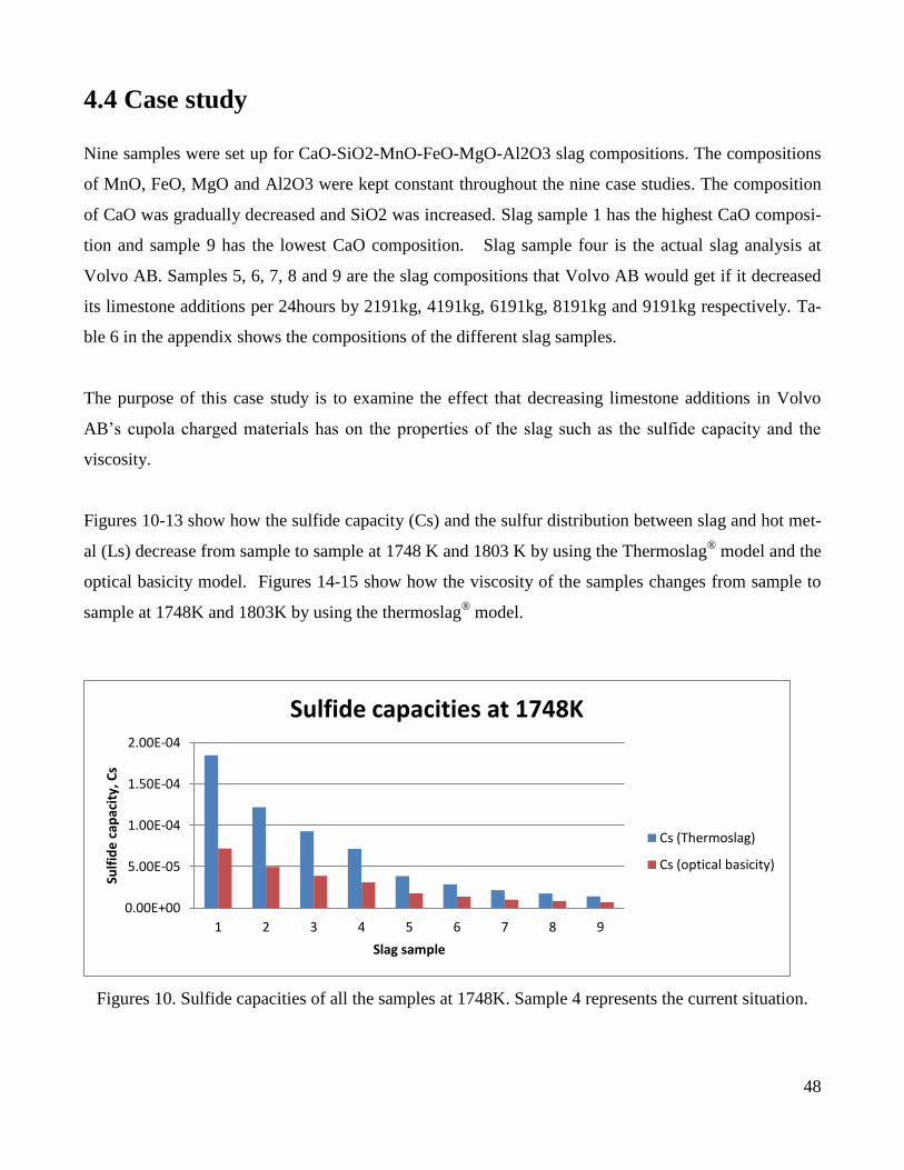
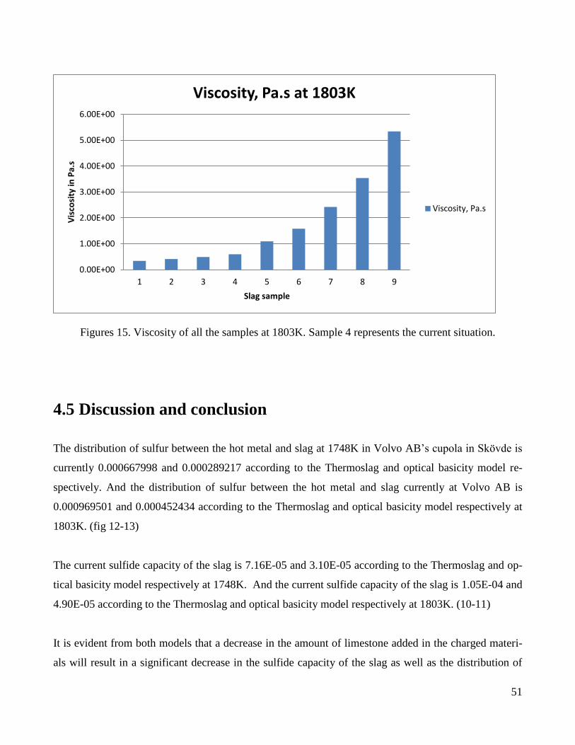
4.4 Case study
Nine samples were set up for CaO-SiO2-MnO-FeO-MgO-Al2O3 slag compositions. The compositions
of MnO, FeO, MgO and Al2O3 were kept constant throughout the nine case studies. The composition
of CaO was gradually decreased and SiO2 was increased. Slag sample 1 has the highest CaO composi-
tion and sample 9 has the lowest CaO composition. Slag sample four is the actual slag analysis at
Volvo AB. Samples 5, 6, 7, 8 and 9 are the slag compositions that Volvo AB would get if it decreased
its limestone additions per 24hours by 2191kg, 4191kg, 6191kg, 8191kg and 9191kg respectively. Ta-
ble 6 in the appendix shows the compositions of the different slag samples.
The purpose of this case study is to examine the effect that decreasing limestone additions in Volvo
AB’s cupola charged materials has on the properties of the slag such as the sulfide capacity and the
viscosity.
Figures 10-13 show how the sulfide capacity (Cs) and the sulfur distribution between slag and hot met-
al (Ls) decrease from sample to sample at 1748 K and 1803 K by using the Thermoslag® model and the
optical basicity model. Figures 14-15 show how the viscosity of the samples changes from sample to
sample at 1748K and 1803K by using the thermoslag® model.
Figures 10. Sulfide capacities of all the samples at 1748K. Sample 4 represents the current situation.
0.00E+00
5.00E-05
1.00E-04
1.50E-04
2.00E-04
1 2 3 4 5 6 7 8 9
Sulf
ide
cap
acit
y, C
s
Slag sample
Sulfide capacities at 1748K
Cs (Thermoslag)
Cs (optical basicity)
Page 50
49
Figures 11. Sulfide capacities of all the samples at 1803K. Sample 4 represents the current situation.
Figures 12. Distribution of sulfur between slag and hot metal at 1748K. Sample 4 represents the current
situation.
0.00E+00
5.00E-05
1.00E-04
1.50E-04
2.00E-04
2.50E-04
3.00E-04
1 2 3 4 5 6 7 8 9
Sulf
ide
cap
acit
y, C
s
Slag sample
Sulfide capacities at 1803K
Cs (Thermoslag)
Cs (optical basicity)
0
0.0002
0.0004
0.0006
0.0008
0.001
0.0012
0.0014
0.0016
1 2 3 4 5 6 7 8 9
Dis
trib
uti
on
of
S b
etw
ee
n s
lag
and
ho
t m
eta
l, Ls
Slag sample
Distribution of sulfur between slag and hot metal at 1748K
Ls(Thermoslag)
Ls(optical basicity)
Page 51
50
Figures 13. Distribution of sulfur between slag and hot metal at 1748K. Sample 4 represents the current
situation.
Figures 14. Viscosity of all the samples at 1748K. Sample 4 represents the current situation.
0
0.0005
0.001
0.0015
0.002
0.0025
1 2 3 4 5 6 7 8 9 Dis
trib
uti
on
of
sulf
ur
be
twe
en
sla
g an
d h
ot
me
tal,
Ls
Slag sample
Distribution of sulfur between slag and hot metal at 1803K
Ls (Thermoslag)
Ls (optical basicity)
0.00E+00
1.00E+00
2.00E+00
3.00E+00
4.00E+00
5.00E+00
6.00E+00
7.00E+00
8.00E+00
9.00E+00
1 2 3 4 5 6 7 8 9
Vis
cosi
ty in
Pa.
s
Slag sample
Viscosity, Pa.s at 1748
Viscosity, Pa.s
Page 52
51
Figures 15. Viscosity of all the samples at 1803K. Sample 4 represents the current situation.
4.5 Discussion and conclusion
The distribution of sulfur between the hot metal and slag at 1748K in Volvo AB’s cupola in Skövde is
currently 0.000667998 and 0.000289217 according to the Thermoslag and optical basicity model re-
spectively. And the distribution of sulfur between the hot metal and slag currently at Volvo AB is
0.000969501 and 0.000452434 according to the Thermoslag and optical basicity model respectively at
1803K. (fig 12-13)
The current sulfide capacity of the slag is 7.16E-05 and 3.10E-05 according to the Thermoslag and op-
tical basicity model respectively at 1748K. And the current sulfide capacity of the slag is 1.05E-04 and
4.90E-05 according to the Thermoslag and optical basicity model respectively at 1803K. (10-11)
It is evident from both models that a decrease in the amount of limestone added in the charged materi-
als will result in a significant decrease in the sulfide capacity of the slag as well as the distribution of
0.00E+00
1.00E+00
2.00E+00
3.00E+00
4.00E+00
5.00E+00
6.00E+00
1 2 3 4 5 6 7 8 9
Vis
cosi
ty in
Pa.
s
Slag sample
Viscosity, Pa.s at 1803K
Viscosity, Pa.s
Page 53
52
sulfur between the slag and the hot metal (fig 10-13). For example, a decrease with 6191kg in the add-
ed charged limestone will decrease the distribution of sulfur between slag and hot metal from 0.00097
to 0.00036 at 1803K according to the Thermoslag model. And a decrease in 6191kg in the added
charged limestone will decrease the distribution of sulfur between slag and hot metal from 0.00045 to
0.00016 at 1803K according to the optical basicity model.
However, figures 14 and 15 show that as the amount of charged limestone is decreased, the viscosity of
the slag increases noticeably. This is a disadvantage since the viscosity of the slag has a significant in-
fluence on the ability to tap the slag from the cupola.
A more interesting method of increasing the sulfur pickup of the hot metal without decreasing the vis-
cosity of the slag is to add CaS as a fluxing material instead of limestone. CaS would serve as a fluxing
agent and would also increase the sulfur amounts in the hot metal without increasing the viscosity. This
is thermodynamically possible from the equilibrium reaction of CaS with dissolved oxygen:
CaS + O CaO + S
However, it is important to point out that the rate at which this reaction would occur should be investi-
gated in order to conclude whether this method is effective.
Finally, the most common method of sulfur additions in the hot metal in foundries is sulfur additions in
the form of cored wire. Cored wire is used in ferrous metallurgy for after-furnace treatment of the hot
metal. A Cored wire is a thin-walled steel shell with filler inside in the form of powder and/or granules.
Cored wire can be supplied in boxes, coils packed or on pallets. During the hot metal treatment, the
wire is fed into the ladles by injection machines. Sulfur in the form of cored wire is relatively free from
impurities and can therefore be used without danger of contaminating. Cored wire is currently
delivered by various companies. [31-35]
The advantage of cored-wire injection is that the content powder is released close to the bottom of the
ladle, under high ferrostatic pressure and far away from oxidation sources. This results in a better
recovery compared to traditional lump or powder additions of sulfur since sulfur is highly oxidizable
and has a low density. [31-35]
Page 54
53
Chapter 5- Slag enthalpies of Thermocalc® and
Rawmatmix®: A parameter study
5.1 Introduction
The importance of understanding the properties of slags in metallurgical processes can be realized by
the world-wide efforts to measure and model the slag properties. The slag properties are commonly
divided into two parts [36];
Part 1: The thermo-chemical properties
These properties include of the integral molar properties like enthalpies and integral molar Gibbs
energies as well as partial molar properties like the activities of the slag components.
Part 2: The thermo-physical properties
These properties include viscosities, thermal diffusivities and surface tensions.
Molar volumes come under the physical properties as densities; however, it can also be classified under
thermochemical properties. The specific heats are common to both categories. Slag properties such as
the enthalpies are important for process optimization, thermochemical modeling and heat and mass
transfer calculations [36]. In this chapter, the difference in the cupola slag enthalpies of two engineering
softwares; Thermocalc®
and Rawmatmix® are compared. Linear regression using the least square
approach is used to obtain more accurate slag enthalpies and specific heats (Cp values) for
Rawmatmix®. Slag-metal equilibrium calculations are also carried out for Volvo AB’s cupola furnace
using Thermocalc®.
5.2 Thermocalc®
Thermo-Calc is a powerful software package, founded in 1997 as an offspring from The Royal Institute
of Technology, KTH. The main use of this software is to solve thermodynamic and phase diagram cal-
culations for multi-component systems. The calculations of this software are based on thermodynamic
databases which are obtained by professional evaluation of experimental data using the CALPHAD
Page 55
54
technique. The available databases include steels, Ti-, Al-, Mg-, Ni-alloys, multi-component oxides.
[37]
5.3 Rawmatmix®
Rawmatmix is a powerful software package, launched in 2011 by an offspring company of The Royal
Institute of Technology, KTH. Rawmatmix is a raw material optimization tool for metallurgical furnac-
es which is developed to help steel makers and foundries to choose the optimum charge mixtures that
satisfies the desired analysis and achieves the minimum cost. The available furnace models currently
are Carbon steel EAF melting furnace, Stainless steel EAF melting and reduction furnace and Induction
Furnace Model. [38]
5.4 Linear regression
Linear regression is a useful statistical technique. Its models are very powerful, and can empirically
obtain very complicated relationships between variables. Regression refers to the fact that the observed
data tend to “regress” towards their average value even though are variable. Linear refers to the type of
equation used in the models. The most popular form of linear regression is the least squares fitting. The
least square fitting provides a solution to the problem by finding the best fitting straight line through a
set of points. [39]
5.5 Parameter study
Both Rawmatmix® and Thermocal have a thermodynamic databases used to calculate enthalpies of
metals, slags and gases. In the thermocalc software, the heat of formation, super-heating, mixing and
melting of the slag are included in the slag thermodynamic database. However, in Rawmatmix software
only the heat of formation and super-heating of the slag are included in the slag thermodynamic data-
base. A parameter study was therefore conducted to compare the enthalpies of different cupola slag
compositions using both softwares in order to obtain the more accurate slag enthalpies and specific
heats (Cp values) for Rawmatmix®. The enthalpy differences between the softwares were then ex-
pressed as temperature difference. The parameter study comprised of 13 different slag compositions at
Page 56
55
CaO SiO2 FeO MnO MgO Al2O3 T
1 38.0 48.4 0.5 3.5 1.9 7.7 1723.0
2 15.4 66.0 0.7 4.8 2.6 10.5 1723.0
3 54.1 35.8 0.4 2.6 1.4 5.7 1723.0
4 58.2 21.0 0.8 5.4 2.9 11.8 1723.0
5 35.3 52.1 0.5 3.2 1.8 7.1 1723.0
6 38.1 48.5 0.3 3.5 1.9 7.7 1723.0
7 36.7 46.7 3.9 3.4 1.8 7.4 1723.0
8 39.3 50.1 0.5 0.2 2.0 8.0 1723.0
9 37.6 47.8 0.5 4.6 1.9 7.6 1723.0
10 38.4 48.9 0.5 3.5 0.9 7.8 1723.0
11 26.4 33.6 0.3 2.4 31.9 5.3 1723.0
12 38.7 49.3 0.5 3.6 1.9 6.0 1723.0
13 32.0 40.7 0.4 2.9 1.6 22.3 1723.0
14 38.0 48.4 0.5 3.5 1.9 7.7 1500.0
15 38.0 48.4 0.5 3.5 1.9 7.7 1900.0
four different temperatures (1623K, 1723K, 1823K and 1923K). The total cases used in the parameter
study were thus 52. Table 5 below shows the slag composition used for the parameter study.
Table 5. Slag composition used for the parameter study
The enthalpy of each case has been calculated according to
Where
is the reference enthalpy at 1700K including the energy of heating, mixing and solv-
ing the component
is the reference temperature of 1700 K
is the temperature
is the specific heat of each component
is the amount of each component in moles
is the enthalpy calculated by ThermoCalc
A total of 52 different cases (13 different compositions and four different temperatures) have been used
to determine the and with least square method. Table 6 below shows the obtained
and .
Figures 16-17 show the difference of Thermocalc-model and the Rawmatmix enthalpy model
expressed as difference in temperature before and after the case study respectively. It is evident from
these figures that the standard deviation of the error between the RAWMATMIX enthalpy model and
ThermoCalc decreased from 64K to 32K.
Page 57
56
Table 6. The calculated and
CaO SiO2 FeO MnO MgO Al2O3
-577000 -814540 -158840 -148160 -516220 -1405200
83 41 40 253 111 175
Figure 16. The difference of Thermocalc-model and the Rawmatmix enthalpy model expressed as
difference in temperature (before the case study)
Figure 17. The difference of Thermocalc-model and the Rawmatmix enthalpy model expressed as
difference in temperature (after the case study)
-250
-200
-150
-100
-50
0
50
100
150
200
250
1 2 3 4 5 6 7 8 9 10 11 12 13
Tem
pe
ratu
re d
iffe
ren
ce (
K)
Case
ThermoCalc vs RAWMATMIX Entalphy model
1623 K
1723 K
1823 K
1923 K
-250
-200
-150
-100
-50
0
50
100
150
200
250
1 2 3 4 5 6 7 8 9 10 11 12 13
Tem
pe
ratu
re d
iffe
ren
ce (
K)
Case
ThermoCalc vs RAWMATMIX Entalphy model
1623 K
1723 K
1823 K
1923 K
Page 58
57
5.6 Slag-metal equilibrium calculations
Thermocalc software was used to calculate whether equilibrium conditions exist between the slag and
metal of Volvo AB’s cupola. In doing so, the databases SLAG2 and TCFE6 were used. The calcula-
tions for the equilibrium between the top slag and steel melt, however, resulted a large theoretical gas
phase. This could perhaps indicate that an equilibrium condition does not exist between the top slag
and the metal bulk in the cupola.
5.7 Discussion and conclusion
In this chapter, the cupola slag enthalpies of two engineering softwares; Thermocalc® and
Rawmatmix® were compared. Both Rawmatmix
® and Thermocal have a thermodynamic databases
used to calculate enthalpies of metals, slags and gases. In the Thermocalc software, the heat of for-
mation, super-heating, mixing and melting of the slag are included in the slag thermodynamic database.
However, in Rawmatmix software only the heat of formation and super-heating of the slag are included
in the slag thermodynamic database.
A parameter study was therefore conducted to compare the enthalpies of different cupola slag composi-
tions using both softwares in order to obtain the more accurate slag enthalpies and specific heats (Cp
values) for Rawmatmix®. The enthalpy differences between the softwares were then expressed as tem-
perature difference. The parameter study comprised of 13 different slag compositions at four different
temperatures (1623K, 1723K, 1823K and 1923K). The total cases used in the parameter study were
thus 52.
It is interesting to note that when the enthalpy difference of both softwares expressed as temperature
difference were calculated and compared, it was obtained that the standard deviation was 64 K.
However, when the new enthalpy and Cp values obtained through linear regression were included in
the Rawmatmix model calculation, it was obtained that the standard deviation decreased to 32K.
Slag-metal equilibrium calculations were also carried out for Volvo Group Trucks Operations’ cupola
furnace using Thermocalc®. Thermocalc software was used to calculate whether equilibrium conditions
existed between the slag and metal of Volvo AB’s cupola. In doing so, the databases SLAG2 and
TCFE6 were used. The calculations for the equilibrium between the top slag and steel melt, however,
Page 59
58
resulted a large theoretical gas phase. This could perhaps indicate that an equilibrium condition does
not exist between the top slag and the metal bulk in the cupola.
Page 60
59
Chapter 6 - Conclusion
The objective of this master thesis was to evaluate the cupola furnace operations of Volvo Group
Trucks Operations in Skövde, Sweden.
This evaluation was done by developing two accurate mass and heat balance process model for it. The
data used for the development of the mass and heat balances were obtained from Volvo Group Trucks
Operations. The first process model assumed that the oxygen present in the off-gas analysis is from top
air leakage. The second process model assumed that the oxygen present in the off-gas analysis is from
the oxygen injected through the tuyeres as blast air.
In the first scenario, it has been calculated that, approx. 1298 Nm3/h of air leakage is entering the
cupola from the top as leakage. This large amount of air leakage is reasonable since there is an under-
pressure at the top of the cupola.
It is also interesting to note that the amount of blast air required for the two scenarios are slightly
different. In the first scenario, the calculated air flow was 1100 Nm3/h less than the air flow
measurements provided by Volvo AB. However, in the second scenario, the calculated amount of air
flow was found to be the same as the air flow measurements at Volvo AB.
Typical ranges of losses and gains of elements in an acid lined cupola are as follows [3, 6]:
Silicon : 7 - 12% loss
Manganese : 10 - 20% loss
Sulphur: 40 - 60% gain
It has been calculated that the silicon and manganese losses of Volvo AB’s cupola were 32 and 20 per-
cent of the elements in the charge respectively. The silicon losses are considerably higher than the nor-
mal acceptable losses. The manganese losses are just in the range of expected acceptable losses. The
sulfur gains have been calculated to be 19% of weight charged, which is also lower than what is ex-
pected.
Page 61
60
There is no usual maximum acceptable range of Al loss in cupolas, since Al is a harmful element in cast
iron. The Al loss of Volvo AB’s cupola has been calculated to be 75%. This loss is understandable since
Al has a much higher affinity to oxygen than Si and Mn.
It has been explained previously in this report that a higher percentage of carbon dioxide in the off gas-
es analysis means that there is a more complete combustion of the coke, and release of a larger amount
of the potential heat in the fuel. Thus, increasing the carbon dioxide in the off gases analysis will de-
crease the cost of coke per ton of iron melted. Only from the standpoint of coke economy, it is obvious
that certain savings will result from more complete combustion. However, as the efficiency of the of
the combustion increases, the losses of silicon and manganese increase due to oxidation losses resulting
from a decrease in the reducing conditions in the furnace. Therefore, maximum economy is not
achieved with maximum efficiency of combustion but a balance between combustion efficiency and
losses due to oxidation.
In order to improve the metallurgical and economic operation and efficiency of the cupola, some im-
provements must be made to reduce these high oxidation losses. This can be done by causing the condi-
tion inside the cupola furnace to be more reducing which in turn can be obtained by decreasing the
combustion efficiency of the cupola.
Also, 129 sample analysis of the output hot metal were provided by Volvo Group Trucks Operations
along with the tolerance level on all the elements. The average values of all the elements and the
standard deviations have been calculated. Also, the 95% confidence intervals of the elements have been
calculated. It is evident from the 95% confidence interval that the output metal analyses of the samples
provided are within the range of their tolerance level, except for sulfur. Sulfur in the hot metal is lower
than the desired range. Chapter 4 of this thesis is dedicated to ways of increasing sulfur in hot metal.
Heat losses to the surroundings were also calculated for both process models. In the first process
model, the heat losses over a period of 24hours were calculated to be approx.143167 kWh. In the
second process model, the heat losses over a period of 24 hours were calculated to be approximately
169600 kWh. The heat losses to the surroundings are less in the model assuming air leakage because
some of the heat will be used to heat up the air leakage.
Page 62
61
This thesis also included exploring the possibility of increasing sulfur pickup of the cupola hot metal by
controlling the flux and slag. For the purpose of this investigation, a case study was set up to examine
the effect that decreasing limestone additions in Volvo AB’s cupola charged materials has on the prop-
erties of the slag such as the sulfide capacity and the viscosity. Thermoslag software and optical basici-
ty model were used in the case study.
It was found that a decrease in the amount of limestone added in the charged materials will result in a
significant decrease in the sulfide capacity of the slag as well as the distribution of sulfur between the
slag and the hot metal. For example, a decrease in 6191kg in the added charged limestone will decrease
the distribution of sulfur between slag and hot metal from 0.00097 to 0.00036 at 1803K according to
the Thermoslag model. And a decrease in 6191kg in the added charged limestone will decrease the dis-
tribution of sulfur between slag and hot metal from 0.00045 to 0.00016 at 1803K according to the opti-
cal basicity model.
However, as the amount of charged limestone was decreased, the viscosity of the slag increased
noticeably. This was a disadvantage since the viscosity of the slag has a significant influence on the
ability to tap the slag from the cupola.
The sulfur pick up in the cupola hot metal, can be increased to the desired range by increasing the sul-
fur input through coke (i.e. increase coke amounts) or by reducing the metallic charge.
Other interesting methods of increasing the sulfur pickup of the hot metal without decreasing the vis-
cosity of the slag were also suggested such as addition of CaS as a fluxing material instead of lime-
stone. CaS would serve as a fluxing agent and would also increase the sulfur amounts in the hot metal
without increasing the viscosity. This is thermodynamically possible from the equilibrium reaction of
CaS with dissolved oxygen:
CaS + O CaO + S
However, it is important to point out that the rate at which this reaction would occur should be investi-
gated in order to conclude whether this method is effective.
Page 63
62
Sulfur addition in the hot metal in the form of cored wire has been proposed. Cored wire is used in
ferrous metallurgy for after-furnace treatment of the hot metal. A Cored wire is a thin-walled steel shell
with filler inside in the form of powder and/or granules. Cored wire can be supplied in boxes, coils
packed or on pallets. During the hot metal treatment, the wire is fed into the ladles by injection
machines. Sulfur in the form of cored wire is relatively free from impurities and can therefore be used
without danger of contaminating. Cored wire is currently delivered by various companies. [35-38]
The advantage of cored-wire injection is that the content powder is released close to the bottom of the
ladle, under high ferrostatic pressure and far away from oxidation sources. This results in a better
recovery compared to traditional lump or powder additions of sulfur since sulfur is highly oxidizable
and has a low density. [31-35]
The final part of this work was a further development of the Rawmatmix® software developed by an
offspring company from the Royal Institute of Technology, KTH. The objective of that final part of the
thesis was to compare the enthalpies of different cupola slag compositions using Rawmatmix®
and
Thermocalc® in order to improve the slag enthalpies and specific heats (Cp) values of Rawmatmix
®
software.
A parameter study was therefore conducted to compare the enthalpies of different cupola slag composi-
tions using both softwares in order to obtain the more accurate slag enthalpies and specific heats (Cp
values) for Rawmatmix®. The enthalpy differences between the softwares were then expressed as tem-
perature difference. The parameter study comprised of 13 different slag compositions at four different
temperatures (1623K, 1723K, 1823K and 1923K). The total cases used in the parameter study were
thus 52.
It is interesting to note that when the enthalpy difference of both softwares expressed as temperature
difference were calculated and compared, it was obtained that the standard deviation was 64 K.
However, when the new enthalpy and Cp values obtained through linear regression were included in
the Rawmatmix model calculation, it was obtained that the standard deviation decreased to 32K.
Slag-metal equilibrium calculations were also carried out for Volvo Group Trucks Operations’ cupola
furnace using thermocalc®. Thermocalc software was used to calculate whether equilibrium conditions
Page 64
63
existed between the slag and metal of Volvo AB’s cupola. In doing so, the databases SLAG2 and
TCFE6 were used. The calculations for the equilibrium between the top slag and steel melt, however,
resulted a large theoretical gas phase. This could perhaps indicate that an equilibrium condition does
not exist between the top slag and the metal bulk in the cupola.
Page 65
64
Chapter 7- Further Work
Following the investigations described in this thesis, the following projects could be taken up:
- A further investigation on the possibility of CaS usage instead of limetone in the cupola furnace
- A further study of the cupola slags’ sulfide capacities and viscosities by comparing thermoslag
and optical basicity results with industrial data.
- A further study investigating to which extent the rust on the metallic materials contributes to Si
oxidation losses
Page 66
65
References
[1] Beeley, P., Foundry Technology, (2nd ed.), Oxford, UK: Butterworth-Heinemann, 2001
[2] Campbell, J., Castings (2nd ed.), Oxford, UK: Butterworth-Heinemann, 2003
[3] Davis, J.R., Cast Irons, ASM Specialty Handbook. ASM International, 1996, pages 3-7
[4] Callister, W.D., Materials Science and Engineering an Introduction, 2007
[5] Swedish Foundry Association and the Swedish Foundry Engineering Society, nr 3/2012 (file102)
[6] American Foundrymen's society, The cupola and its operations, (3rd ed.), published by the American Foundrymen's
society, 1965.
[7] http://www.volvogroup.com/group/global/en-
gb/newsmedia/pressreleases/previous/2007/_layouts/CWP.Internet.VolvoCom/NewsItem.aspx?News.It
emId=34213&News.Language=en-gb
[8] http://www.calphad.com/iron-carbon.html
[9] www.sae.org/events/bce/tutorial-ihm.pdf
[10] Sil'man, G. I., Carbon Equivalents of Elements in Cast Iron, Metal Science and Heat Treatment,
2002, Volume 44, Numbers 1-2, Pages 28-31
[11] http://www.keytometals.com/page.aspx?ID=CheckArticle&site=kts&NM=20
[12] Larsen, E.D., Intelligent Control of Cupola Melting, Lockheed Martin Idaho Technologies
Company, June 1997
Page 67
66
[13] Hopkins, E., Basic Cupola Rules Still Apply, Modem Casting Vol. 10, 1995, pp. 38
[14] http://www.hdowns.co.uk/hdweb_melting_page.htm
[15] Rao, P., Manufacturing technology: foundry, forming and welding, (2nd ed.), Tata McGraw-Hill
Education, 2001 pages 182- 185
[16] Rajender, S., Introduction to basic manufacturing processes and workshop technology, New Age
International Pvt Ltd Publishers, 2006
[17] Sy K., Cupola furnace computer process model, Katz Associates, 2004
available at http://www.scribd.com/doc/57016765/Cupola-Furnace2
[18] Kaushish J. P., Manufacturing Processes, (2nd ed.), Prentice-Hall of India Pvt.Ltd, 2010
[19]British Cast Iron Research Association, Cupola design, operation and control, (1st edition), BCIRA
1979
[20] Heine W. R., Loper C. R., and Rosenthal P. C., Principal of Metal Casting, Tata McGraw
Publishing Company Ltd, 1994, pp 530-535.
[21] Abramov G., Foundry Practice, Mir Publisher,1986, Moscow.
[22] Jain P L., Principle of Foundry Technology, Tata McGraw Publishing Company Ltd, Reading.
1993
[23] Bureau of energy efficiency; www.enercon.gov.pk/images/pdf/1ch4.pdf
[24] Fine, A. H., Geiger H., Handbook on Material and Energy Balance Calculations in Metallurgical
Processes, 1980.
[25] http://www.ductile.org/magazine/2002_2/faqs.htm
Page 68
67
[26] Seetharaman, S., Sichen, Du., and Zhang, J. Y., The computer-based study of multicomponent
slag viscosities, JOM Journal of the Minerals, Metals and Materials Society ,Volume 51, Number 8,
38-40,
[27] Teng, L., Matsushita, T., and Seetharaman, S., Challenges in process metallurgy, Association of
Metallurgical Engineers of Serbia Review paper
Available at http://metalurgija.org.rs/mjom/vol12/No%204/3TENG.pdf
[28] Sosinsky D. J., Sommerville I. D., The composition and temperature dependence of the sulfide capacity of
metallurgical slags. Metallurgical Transactions B. Vol. 17B (1986) No. 6. P.331-337
[29] Young. R. W. et al., Use of optical basicity concept for determining phosphorus and sulfur slag-metal partitions.
Ironmaking and Steelmaking. Vol. 19 (1992) No. 3 p.201-211
[30] Nakamura T., Ueda Y., Jpn. Inst. Met..Vol. 50 (1986). p. 456-461
[31] http://www.yuber.com.tr/yeni/ozlutelKatalog.pdf
[32] http://www.mckeowninternational.com/cored-wire.html
[33] http://wirefeedingmachine.com/alloycoredwire.html#sulphur
[34] http://www.sarthakmetalsindia.com/cored-wires.htm
[35] Wu, R. Z. Influence of sulphur addition by cored wire injection on machinability of grey iron,.
Ironmaking & Steelmaking, 2008, Vol.35(8), pp.638-640
[36] Mikael Persson, Investigations of Slag Properties and Reactions, Doctoral Thesis, KTH School of
Industrial Engineering and Management, Division of Materials Process Science Royal Institute of
Technology, Stockholm, 2007
[37] http://www.thermocalc.com/
Page 69
68
[38] www.rawmatmix.com
[39] http://www.esm.ucsb.edu/academics/courses/206/Readings/readerCh8.pdf
[40] Knacke O., Kybaschewski O., Hesselmann K.: Thermo-chemical Properties of Inorganic
Substances. Second edition. (Springer-Verlag) 1991