119
External fire spread Ronni Bech s991634 [email protected] Anders Dragsted s991595 [email protected] BYG • DTU Department of Civil Engineering July 2005

External fire spread
Ronni Bech
s991634 [email protected]
Anders Dragsted s991595
BYG • DTU Department of Civil Engineering
July 2005

Preface External fire spread
Preface
This final thesis is written by Ronni Bech and Anders Dragsted for completion of the degree of Master of Engineering at BYG•DTU in the spring semester 2005. The thesis is written in co-operation with the Birch & Krogboe/Arup alliance. We would like to thank the following for their help during the writing process: Senior Fire Engineer Bruce Kelly, Arup Fire, for supervision, inspiration and constructive criticism all the way through the process. Master in Fire Safety Annemarie Poulsen, Birch & Krogboe, for help in the beginning of our writing process. Associate Professor Lars Schiøtt Sørensen, BYG•DTU, for making this project possible by being our official DTU supervisor and trusting our external supervisors. BYG•DTU Lundtofte 1st of July 2005
Ronni Bech s991634
Anders Dragsted s991595
I

Abstract External fire spread
Abstract
Fire spreading between external openings in buildings has previously caused the loss of many lives. Moore recently, the number of fatalities has decreased and the risk is now mostly to the loss of property and market shares. Since the late fifties the phenomenon of external fire spread has been studied throughout a number of small- and full-scale research programs and from the nineties supplemented by several numerical simulations. This thesis describes and discusses the previous findings and results and compares them to each other and to the general theory of fire technology. The various stages of the fire spread are described in chronological order to give a continuous understanding of the problem. Additionally, different precautions to reduce the risk of external fire spread are described and discussed. A potential approach to evaluate the risk of external fire spread is proposed through a step-by-step guideline. Not all steps are fully researched and statistical data are needed for risk calculations. The general conclusion is that qualified judgment is needed in all aspects of the hazard assessment and that more research is required in order to fully cover the phenomenon of external fire spread.
II
Resumé (Danish abstract) External fire spread
Resumé (Danish abstract)
Brandspredning mellem udvendige åbninger i bygninger har tidligere kostet mange menneskeliv. I den senere tid er antallet dog faldet og dette fænomen er nu primært en økonomisk risiko pga. materielle skader og tab af markedsandele. Siden slutningen af halvtredserne er udvendig brandspredning blevet undersøgt gennem et antal forsøg i reduceret og fuld skala og er siden halvfemserne suppleret med computersimuleringer. Dette projekt beskriver og diskuterer konklusioner og resultater fra disse og sammenligner dem med hinanden og med den generelle brandteori. De enkelte faser i brandspredningen er beskrevet kronologisk for at give en sammenhængende forståelse af problemstillingen. Derudover beskrives og diskuteres forskellige foranstaltninger til reducering af risikoen for udvendig brandspredning. En mulig fremgangsmåde til at undersøge risikoen for udvendig brandspredning er foreslået, men ikke alle forhold er fuldt ud udforsket og det statistiske materiale er utilstrækkeligt. Den generelle konklusion er at kvalificerede vurderinger er nødvendige i alle dele af risikovurderingen og at videre undersøgelser er påkrævet for helt at afdække fænomenet udvendig brandspredning.
III

Index External fire spread
Index
PREFACE ................................................................................................................................. I
ABSTRACT .............................................................................................................................II
RESUMÉ (DANISH ABSTRACT) ...................................................................................... III
1. INTRODUCTION ................................................................................................................1 1.1. BACKGROUND ..................................................................................................................1 1.2. OBJECTIVE........................................................................................................................1 1.3. STRUCTURE ......................................................................................................................2
2. THE CONCEPT OF EXTERNAL FIRE SPREAD..........................................................3
3. ASSUMPTIONS AND LIMITATIONS .............................................................................7
4. CONDITIONS FOR EXTERNAL FLAMES ....................................................................9 4.1. INITIAL FIRE......................................................................................................................9
4.1.1. Fuel.....................................................................................................................9 4.1.2. Geometry ..........................................................................................................10 4.1.3. Openings...........................................................................................................10
4.2. PLUME FIRE ....................................................................................................................11 4.2.1. Ventilation ........................................................................................................11 4.2.2. Energy release ..................................................................................................14
4.3. CEILING JETS ..................................................................................................................17 4.4. HOT GAS LAYER..............................................................................................................20 4.5. EXTERNAL FLAMES.........................................................................................................20
5. BEHAVIOUR AND DIMENSIONS OF EXTERNAL FLAMES AND PLUMES ......22
5.1. PLUME PROPERTIES.........................................................................................................22 5.1.1. Free or enclosed burning .................................................................................22 5.1.2. Flame regions ...................................................................................................22 5.1.3. Behaviour .........................................................................................................23
5.2. DIMENSIONS OF EXTERNAL FLAMES ...............................................................................26 5.2.1. The flame shape................................................................................................27 5.2.2. Definition of flame tip.......................................................................................29 5.2.3. Flame height .....................................................................................................30 5.2.4. Flame length along axis ...................................................................................32 5.2.5. Distance from wall to flame .............................................................................33 5.2.6. Flame width ......................................................................................................35 5.2.7. Flame thickness ................................................................................................36 5.2.8. Deflection by wind............................................................................................36
6. FLAME TEMPERATURES .............................................................................................39 6.1. FLAMES IN GENERAL ......................................................................................................39 6.2. TEMPERATURE DISTRIBUTION IN EXTERNAL FLAMES......................................................41 6.3. DISCUSSION....................................................................................................................44
7. HEAT TRANSFER ............................................................................................................45
IV
Index External fire spread
7.1. RADIATION .....................................................................................................................45 7.1.1. Emissivity..........................................................................................................45 7.1.2. Configuration factor .........................................................................................47 7.1.3. Radiation from external flames ........................................................................49
7.2. CONVECTION ..................................................................................................................51 7.2.1. Natural or forced..............................................................................................51 7.2.2. Heat flux ...........................................................................................................51 7.2.3. Convection from external plumes .....................................................................52
7.3. RADIATION COMPARED TO CONVECTION ........................................................................54
8. IGNITION CRITERIA......................................................................................................57 8.1. DEFINITIONS...................................................................................................................57 8.2. MATERIALS ....................................................................................................................58
8.2.1. Type of materials ..............................................................................................58 8.2.2. Affecting factors................................................................................................58 8.2.3. Thermal thickness .............................................................................................58 8.2.4. Wood.................................................................................................................59 8.2.5. Fabrics..............................................................................................................61 8.2.6. Solid polymers ..................................................................................................63
8.3. SUMMARY ......................................................................................................................64
9. PRECAUTIONS .................................................................................................................66 9.1. SPANDRELS.....................................................................................................................67 9.2. EXTERNAL HORIZONTAL PROJECTIONS ...........................................................................69 9.3. EXTERNAL VERTICAL PROJECTIONS................................................................................74 9.4. GLAZING ........................................................................................................................76
9.4.1. General .............................................................................................................76 9.4.2. Fire-resistant glazing .......................................................................................77 9.4.3. Foil laminates ...................................................................................................79 9.4.4. Insect screens....................................................................................................79 9.4.5. Window sprinklers ............................................................................................80
9.5. SUN SCREENS..................................................................................................................81 9.5.1. Louvres .............................................................................................................81 9.5.2. Blinds................................................................................................................83
9.6. DISCUSSION....................................................................................................................84
10. CONCLUSION .................................................................................................................85 10.1. FINDINGS......................................................................................................................85 10.2. RESEARCH TO BE DONE IN THE FUTURE ........................................................................88
11. NOMENCLATURE .........................................................................................................89
12. REFERENCES .................................................................................................................92
13. APPENDICES...................................................................................................................97 13.1. APPENDIX 1: PREVIOUS STUDIES ..................................................................................97 13.2. APPENDIX 2: EXAMPLES OF ”WALL” AND ”NO-WALL” ..............................................108 13.3. APPENDIX 3: CASE EXAMPLE......................................................................................109
V

Introduction External fire spread
1. Introduction
1.1. Background In the seventies and eighties a series of special fire incidents in high-rise buildings resulted in the loss of many lives and serious material damage. Investigations stated that an essential factor in the hazardous development of the fires was the fire spread from storey to storey via the windows. Throughout the nineties and up till today the number of human fatalities caused by external fire spread has been very low. However, the material damages in reported incidents are still massive. In building codes from all over the world the internal fire compartmentation is described very detailed. This is obvious since the highest risk is still internal fire spread. The external compartmentation is described in much less detail. Often the problem is “solved” by requiring a minimum distance between external openings that is based on thumb rules and tradition. As performance based codes are more widely used, the need for documentation of the risks of external fire spread is growing. Additionally, the trends in building design and the development of materials have made buildings higher and the fraction of façades covered with glass has increased rapidly. These factors make calculation methods even more important. Since 1960 several research projects have investigated different parts of the phenomenon and empirical expressions for estimation of the risks have been developed. In the last fifteen years the increased performance of computers and numerical models have been useful, especially in the investigation of the influence of building geometry. However, there are still uncertainties that need to be explored and more validation of the existing expressions is desirable.
1.2. Objective The objective of this thesis is to examine the phenomenon of fire spreading from one exterior opening in a building to another without the influence of combustible claddings. Guidelines for estimation of the various problems involved will be presented if possible. The objective is carried out through a review of available literature on the topic combined with elaborations and discussions of important issues.
1

Introduction External fire spread
1.3. Structure The objective is reviewed by describing different parts of the phenomena in chronological order from development in the room of fire origin to ignition of combustibles in rooms above or adjacent. Ch. 2 – The concept of external fire spread
The phenomenon is described qualitatively. Ch. 3 – Assumptions and limitations The general and most important assumptions are described. Ch. 4 – Conditions for external flames
Conditions in the room of fire origin leading to external flames are evaluated. Ch. 5 – Behaviour and dimensions of external flames and plumes
The size, orientation and behaviour of external flames are discussed and available estimation methods are presented.
Ch. 6 – Flame temperatures
The temperature of the external flame and plume is discussed in order to calculate the heat transfer to openings.
Ch. 7 – Heat transfer Radiant and convective heat transfer to the building is described. Ch. 8 – Ignition criteria The heat exposure required for ignition of selected materials is described. Ch. 9 – Precautions
Precautions from selected building codes are described and alternatives are discussed.
Ch. 10 – Conclusion All references with the issue of external fire spread without combustible claddings are described in “Previous research” in Appendix 1. Main conclusions, test conditions, scope etc. are shortly described so as to provide an overview and reference for future projects.
2

The concept of external fire spread External fire spread
2. The concept of external fire spread
In this thesis external fire spread is defined as the spread of fire via external openings by radiation and convection from an external plume or flame. The phenomenon is named differently in various references. “Autoexposure”, “leap-frog effect”, “window-to-window propagation” and “re-entering of the fire” are some of the terms used. This thesis will simply refer to it as “external fire spread”. The external plume can occur in two ways:
1. In the initial stage of a fire all combustion is located in the room of fire origin. Later, when the fire has evolved, flames in the ceiling jets can be long enough to eject from the room openings. This can happen when the fire is still fuel-controlled. Figure 1 illustrates the flame extension to an adjacent room but the same will happen from an opening to the outside. However, the external plume will deflect upwards. Especially in buildings with suspended ceilings where the top of the opening is at the same level as the ceiling so there are no obstructions for the ceiling jet to overcome.
Figure 1 – Ceiling jet ejecting from a fire room [16]
2. If the fire becomes ventilation controlled, unburnt volatiles will flow out of the room
openings. When the hot fuels mix with the outside air, combustion (and flames) will occur outside the room if the gas mixture temperature is sufficiently high. Figure 2 illustrates this, again to an adjacent room.
Figure 2 – External burning from ventilation-controlled fire [16]
3

The concept of external fire spread External fire spread
Because of the high temperature differences between the hot fuels and the outside air, the buoyancy is strong and the plume is driven upward along the building façade when it leaves the opening. The physics of the above two phenomena makes it unlikely that they appear at the same time since the first phenomenon is mainly fuel-controlled and the second is ventilation-controlled. When flames and/or hot air is located in front of external openings above the room of fire origin it may result in cracking of glass panes because of the thermal stress across the glass surface induced by radiation and convection. The cracking will not necessarily result in a fall out of the glass but there is a certain possibility that it may happen. The façade could also be open simply because a window is open for ventilation reasons. Then a fraction of the hot air will enter the room and expose its interior to convective heat flux in the opening and the ceiling region. Combustible items in the room, e.g. curtains or furniture placed next to the opening is likely to ignite due to the high heat exposure. Both radiation and convection may contribute to the exposure. When ignition of the room above has occurred it can develop to a stage where flames emerge from the openings and the situation repeats. If two floors are burning the external plume from the lower will affect the plume emerging from the upper. Not only the supply of thermal energy and the upward velocity contributes to the upper plume. The supply of air from the lower plume has a less amount of oxygen and thus, the upper plume must travel longer to obtain full combustion. Selected incidents The BRE, Fire and Risk Sciences Division in the UK have done a major research project on reported incidents where external fire spread was identified as a significant factor [14]. The report lists 18 incidents from all over the world and is not exhaustive, but serves as a representative sample of some of the worst cases. The list is reproduced here to give an idea of the type of buildings and the scope of the incidents.
4

The concept of external fire spread External fire spread
Date Building No. storeys
in building No. storeys involved
No. fatalities
1970-08-05 One New York Plaza, New York 50 2 - 1972 Hotel Tae Yon Kak, South Korea 21 ? 163 1972-02-24 Andraus Building, Sao Paulo, Brazil 31 28 16/20 1973-07-23 Avianca Building, Bogota, Columbia 36 24 4 1974-02-01 Joelma Building, Sao Paulo, Brazil 25 14 179 1979-01-18 Viliers House, London 8-11 6 - 1981-02-10 Las Vegas Hilton 30 23 8 1982-03-06 Westchase Hilton Hotel, Houston,
Texas 13 2 12
1988-05-04 First Interstate Bank 62 4 - 1991-02-23 One Meridian Plaza, Philadelphia 38 9 3 1991-04-05 Knowsley Heights, Huyton,
Merseyside, UK 10 9 -
1991-04-16 Mercantile Credit HQ, Basingstoke, Hampshire, UK
14 3 -
1992-02-15 Los Angeles County Health Building 14 7 - 1993-01-31 Banker’s Trust Building, New York 30-42 2 - 1994-06-15 South African Agricultural Union Bld.,
Pretoria 30 12 -
1996-03-15 Glasgow House, Maida Vale, London 17 2 - 1997-02-23 President Hotel, Bangkok, Thailand 37 4 - 1999-06-11 Garnock Court, Irvine, Scotland 14 9 1
Table 1 - Selected incidents [14]
It is conspicuous that incidents in the last twenty years have caused few fatalities compared to incidents in the early seventies. Although the loss of life is no longer the major problem (probably because of the improvement in fire safety), the economic losses are still high. It can be critical for a company if a part of their administration or production is closed for a period. Even though insurance in most cases covers the material losses and the lack of production, the absence from the market can be very expensive. The longer the production is closed, the more market is lost. Most of the listed incidents happened in buildings or floors where sprinklers were not installed or where the sprinklers were disengaged due to rebuilding, installation service or similar. For example, the One Meridian Plaza Building fire in 1991 started on the 22nd floor that was not sprinklered. Because of external fire spread the floors above were ignited. When the fire reached the 30th floor, which was sprinklered, it stopped. The incidents presented here are all residential or office buildings. This is not strange since high-rise buildings mostly contain these applications. Industrial facilities like production or
5
The concept of external fire spread External fire spread
storages are usually located in low-rise buildings and building geometries where the risk of external fire spread is considered low.
6

Assumptions and limitations External fire spread
3. Assumptions and limitations
In order to limit the extent of this project a number of assumptions have been made. External fire spread The phenomenon of external fire spread is defined in this thesis as the spread of hot gasses and flames from an opening leading to ignition of a material in adjacent rooms. It is assumed that the fire spreads without influence from combustible building components, i.e. the facades of the buildings in question are of non-combustible materials. Building type and use Because of the concept of fire spreading upwards from one floor to another via the outside of the building, it is obvious that high-rise buildings are of greatest interest in this project. Due to the multiple storeys and the increasing use of glass facades, high-rise buildings represent a greater risk with serious consequences in a fire situation. However, the principle of external fire spread still applies for a 2-storey building. A considerable number of multi-storey buildings are used for residential and office purposes and this project will therefore primarily deal with these uses of buildings. The limitation in building type and use has influence on the quantity and type of combustible materials likely to be found in the rooms in question. The design of the building is also limited since the chosen building type normally has a range of floor height and occurrence of openings different from e.g. industry buildings. Flat ceilings are assumed throughout the thesis. Surroundings The external fire spread to surrounding buildings and materials is not considered in this thesis. The fire origin In order to simplify the conditions in the room of fire origin it is assumed that the external opening is unglazed. This condition seems the most likely in case of a fully developed fire. Internal fire spread This thesis only considers external fire spread. It is therefore assumed that any fire spread inside the building is prevented by a sufficient fire compartmentation.
7

Assumptions and limitations External fire spread
Wind conditions Where nothing else is mentioned the effect of the wind is neglected. Mechanical ventilation A mechanical ventilation system within the building would influence the fire behaviour. First, it could contribute to internal fire spread if not properly fire protected. Second, the pressure conditions in case of a fire would be more complicated with a ventilation system installed. For these reasons mechanical ventilation is neglected in this thesis. Fire brigade Since the time and effect of intervention from the fire brigade is difficult to estimate, any attempt of extinction or influence from persons, externally as internally, is neglected. General definitions Some of the concepts used in this thesis are illustrated in Figure 3. It should be noted that “external plume” in some cases includes both hot gasses and flames.
Figure 3 - Definitions of concepts
8

Conditions for external flames External fire spread
4. Conditions for external flames
Traditionally, when an enclosure fire is analysed and described it is divided into four main stages: ignition, growth, fully developed (pre-flashover and post-flashover) and decay. This section will consider the fire differently and the first and last stage will not be discussed here. Instead the growth of the fire leading to the fully developed condition will be emphasized and the criteria for external flames to occur will be described. To get an overview of the build-up of conditions leading to external flames the fire development is considered chronologically according to the following flow chart:
Initial fire
Plume fire
Ceiling jets Hot gas layer
External burning
Flame extensions
Figure 4 - Flow chart of conditions leading to external flames
By describing the conditions of each stage individually as well as how they interact with each other, the flow chart is explained in detail.
4.1. Initial fire As mentioned above the conditions leading to ignition of the initial fire and the ignition itself is of little interest to this thesis. Instead other factors, which are important for the further development of the fire, will be described in the following. It should be noted that in this section the initial fire refers to the stage of a fire just after ignition where no other combustible materials than the ignited fuel package have yet been involved.
4.1.1. Fuel The type and amount of fuel involved in the initial fire is very relevant. These factors affect the duration of the fire as well as the amount of energy released. Weight, density, area of
9

Conditions for external flames External fire spread
surface and porosity are some of the properties that can be considered when evaluating the burning rate of a certain fuel. The limitations of this thesis decrease the number of possible scenarios in relation to the type of fuel. Compared to other building uses, the predominant source of fuels in residential and office buildings are solid materials, which reduces the possibility of pool fires to a minimum. More likely fuel sources are wood based pieces of furniture, fabrics for linings and curtains and paper. Further considerations on combustible materials as fuels are discussed in chapter 8.
4.1.2. Geometry In the initial stage of an enclosure fire the geometry of the room is of great importance for a number of reasons. First, the length and width of the room are decisive for how close the initial fire can be placed to other combustible materials, ventilation openings and the boundaries of the room. The latter condition is important since fuel packages placed near a room wall or corner have different possibilities for growth than freely placed fuels because of the entrainment of air. Second, a small room will more easily be heated by the energy released than a larger room with the same amount of fuel. This is due to a shorter distance for the heat transfer from the flame to walls and ceiling, as well as a larger feedback from hot gasses produced by the initial fire [27]. There are no restrictions to the geometry and size of the initial fire room within the limitations of this thesis. However, it is assumed that any room considered should correspond to a room size comprised by the chosen building category and use.
4.1.3. Openings As mentioned above, ventilation openings also have an impact on the behaviour of the enclosure fire even in the initial stage. As soon as flaming combustion occurs the fire becomes dependent on sufficient oxygen in order to continue growing. That is why even fires in small rooms with sufficient supply of fuel often have a tendency to self extinguish. But the openings do not only regulate whether the initial fire continues to burn. To a certain extent they also control the growth rate and the temperature in the room by exhausting the hot gasses produced. In order to simplify the conditions concerning ventilation it is assumed here that the only possibility for air supply and for hot gas exhaust is through the external opening, i.e. any leakages to surrounding rooms are neglected. It should be noted that later chapters deviate from this assumption.
10

Conditions for external flames External fire spread
A further discussion of ventilation openings and how they control the fire is presented in the next stage of fire development, following the flowchart in Figure 4.
4.2. Plume fire In general, the initial stage of a fire has a number of ways to develop. If the initial fire has a sufficient supply of air, and is allowed to grow, an increasing amount of hot gasses are produced. The colder ambient air surrounds these hot gasses and the density difference creates a plume. There are many factors controlling the plume properties and the development of the fire. Some of these factors are described and discussed in the following sections.
4.2.1. Ventilation The growth of a building fire in the early stage is controlled by the amount and characteristic of the fuel. Such a fuel-controlled fire is well ventilated but as the fire grows there may be insufficient oxygen for the fire. This results in incomplete combustion and excess volatiles, which is controlled by ventilation. In this condition the energy released can be determined by estimating the amount of oxygen entering the compartment opening. Since the ventilation-controlled fire has proved to be most hazardous, a lot of research has been conducted in order to develop some guidelines for determining the transition from fuel- to ventilation-controlled fire. In the work of assessing ventilation conditions in building fires some methods of calculation have been developed. One of the important and well-known terms is the ventilation factor [27]:
Ventilation factor = oo HA [m5/2] (1)
Ao: area of the ventilation opening [m2] Ho: height of the ventilation opening [m] The ventilation factor was derived in 1958 by Kawagoe, primarily through experimental work, and has been implemented in a number of other correlations concerning ventilation. It should be noted, that there are some assumptions associated with the use of any correlation involving the ventilation factor. For instance, in the ventilation-controlled regime of a fire, the gasses in the compartment must be considered to have the same properties uniformly distributed throughout the volume, i.e. well-mixed gasses. Furthermore, the compartment opening is assumed divided by a horizontal neutral plane letting hot gasses leave the room
11

Conditions for external flames External fire spread
above the plane and cold air entering below the plane. This is illustrated in Figure 5 . These assumptions seem reasonable for the issues discussed in this thesis. For compartment fires a variation of the ventilation factor is also used, known as the opening factor [27]:
Opening factor = t
oo
AHA
[m1/2] (2)
At: total enclosure surface area [m2]
Figure 5 – Neutral plane in ventilation-controlled fires [17]
Research has shown that the use of the ventilation factor is valuable in many respects, such as the development of guidelines in determining fuel- or ventilation-controlled fires. Harmathy is one of the researchers who have recommended a method to estimate the distinction between the two regimes of fire [17]. The following correlations are derived from experiments with burning of wood cribs and are suggested applicable for fires involving cellulosic materials:
Ventilation controlled: 235.0<⋅⋅⋅
f
oo
AHAgρ
(3)
Fuel controlled: 290.0>⋅⋅⋅
f
oo
AHAgρ
(4)
ρ: density of air [kg/m3] g: acceleration due to gravity [m/s2]
12

Conditions for external flames External fire spread
Af: surface area of the fuel [m2]
oo HA ⋅ : ventilation factor [m5/2]
Even though the amount of cellulosic fuel is normally dominating in an office or residential building, the correlations have never been proved to be valid for full-scale building fires. According to Drysdale there are also other uncertainties related to the correlations, since they do not take into account the feedback from walls and objects within the compartment [17]. Furthermore, there is a range between the values of 0.235 and 0.290 that is not defined. There is another and more general method for estimating the transition between the two regimes of fire. This method is verified by fire tests conducted with a range of burning materials and involves calculation of the equivalence ratio denoted φ [27]:
φ > 1 for ventilation controlled fires
rmm airf
••
=/φ φ < 1 for fuel controlled fires
(5)
φ: equivalence ratio [-]
: fuel mass loss rate [kg/s] fm•
: air flow rate [kg/s] airm•
r: stoichiometric fuel/air ratio for complete combustion [-]
fm•
and are also called the supply rate of fuel and air, respectively, since they describe
the amount of fuel and air available in the combustion process. The fuel mass loss rate will be discussed in chapter 4.2.2. The stoichiometric fuel/air ratio, r, is determined by considering the equation for complete combustion of the fuel in question. However, since the exact chemical compound of the fuel in an actual building fire is difficult to determine, an estimation of r is necessary.
airm•
By setting up equations for the in- and outflow of air and hot gasses from a compartment like the one showed in Figure 5, it is possible to derive a correlation for the amount of air entering the room:
005.0 HAm air ⋅⋅=
•
[kg/s] (6)
13

Conditions for external flames External fire spread
The derivation of equation (6) is found in several places in the literature with basically the same assumptions attached. For instance, the compartment is filled with stationary gasses at uniform temperature except near the opening. To illustrate the effect of the equivalence ratio on the combustible process, Figure 6 can be considered. Here φ is plotted against a normalized yield for different combustible products, which can be written as ( ) ( )wvivci yy . The subscripts refer to the ventilation-controlled and
the well-ventilated condition respectively.
Figure 6 - Effect of equivalence ratio on yields of combustible products for different materials [27]
4.2.2. Energy release On many occasions the severity of a fire is described simply by the amount of energy released. There are different terms to use for this purpose and they are sometimes confused with each other. Some of the terms used are showed in Table 2.
14
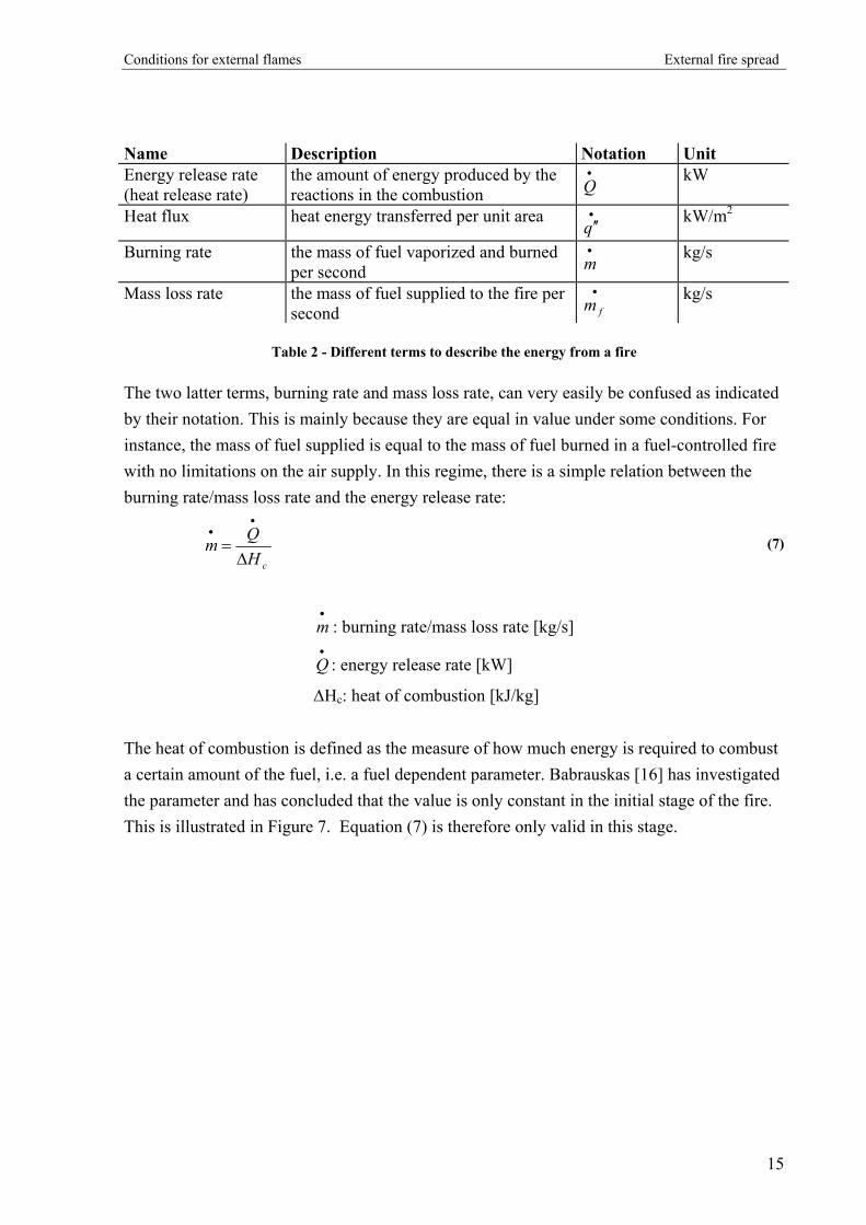
Conditions for external flames External fire spread
Name Description Notation Unit Energy release rate (heat release rate)
the amount of energy produced by the reactions in the combustion
•
Q kW
Heat flux heat energy transferred per unit area •′′q
kW/m2
Burning rate the mass of fuel vaporized and burned per second
•
m kg/s
Mass loss rate the mass of fuel supplied to the fire per second
•
fm kg/s
Table 2 - Different terms to describe the energy from a fire
The two latter terms, burning rate and mass loss rate, can very easily be confused as indicated by their notation. This is mainly because they are equal in value under some conditions. For instance, the mass of fuel supplied is equal to the mass of fuel burned in a fuel-controlled fire with no limitations on the air supply. In this regime, there is a simple relation between the burning rate/mass loss rate and the energy release rate:
cH
Qm∆
=
••
(7)
: burning rate/mass loss rate [kg/s] •
m
Q : energy release rate [kW] •
∆Hc: heat of combustion [kJ/kg] The heat of combustion is defined as the measure of how much energy is required to combust a certain amount of the fuel, i.e. a fuel dependent parameter. Babrauskas [16] has investigated the parameter and has concluded that the value is only constant in the initial stage of the fire. This is illustrated in Figure 7. Equation (7) is therefore only valid in this stage.
15

Conditions for external flames External fire spread
Figure 7 – Example of heat of combustion as a function of time measured from experiments [16]
For the ventilation-controlled regime, the duration of an enclosure fire is almost proportional to the amount of fuel. This means that the burning rate [kg/s] is independent of the amount of fuel. Instead the burning rate is dependent on the size of openings in the room. The burning rate grows with the increase of the area of the opening, and the relationship can be described by the following expression [35]:
oo HAm ⋅=•
09.0 (8)
: burning rate [kg/s] •
mAo: the opening area [m2]
Ho: the opening height in [m] This relationship was proved by Kawagoe in the 1940s by a range of measurements of the burning rate in compartment fires with varying sizes of openings. The experimental work consisted of the burning of wood cribs in both full and reduced scale. However, later on Thomas et al. found that the correlation is only valid for a certain range of
oo HA corresponding to relatively “small openings” [17]. Within this range the fire is
ventilation controlled. The size of “small openings” was not defined. When the area of the opening is enlarged the burning rate becomes independent of the ventilation opening and instead depends on the area and the characteristic of the fuel. Butcher et al. proved this in
16

Conditions for external flames External fire spread
1968 with a number of experiments, which compared two identical rooms with different kinds of fuel beds [17]. In an investigation of conditions leading to external fire spread the ventilation conditions are of great importance. Whether the fire at a given point of time is controlled by the characteristics of the fuel or by the ventilation conditions is decisive for the energy release rate from the fire. However, it can be difficult to determine this by hand and equation (5) is therefore seldom used in practice. Instead experiments and numerical simulations are normally used for determination of the energy release rate [27]. As will be described in the following sections, the energy release rate is necessary in the estimations of the further development of fire.
4.3. Ceiling jets The flow chart in Figure 4 indicates that the plume fire can, in principle, develop in two ways. The most common is by creation of ceiling jets, which will be discussed in this section [16]. When the plume fire grows the flow of gasses from the plume rises towards the ceiling. As the gasses impinge on the ceiling they are forced to spread out radially away from the centreline of the plume, assuming the ceiling is flat. This horizontal flow of hot gasses is known as ceiling jets and is illustrated on Figure 8.
Figure 8 - The principle of a ceiling jet. Reproduced from [27]
The velocities and the temperatures of the ceiling jets are important parameters. By knowing the hot gasses’ velocity it is possible to estimate the time for the radial spread to reach the walls and openings of the compartment. This is important knowledge in the study and estimation of the time for flames to emerge from the opening. Furthermore, the possibilities for the ceiling jets to contribute to a local fire spread within the enclosure can be estimated,
17
Conditions for external flames External fire spread
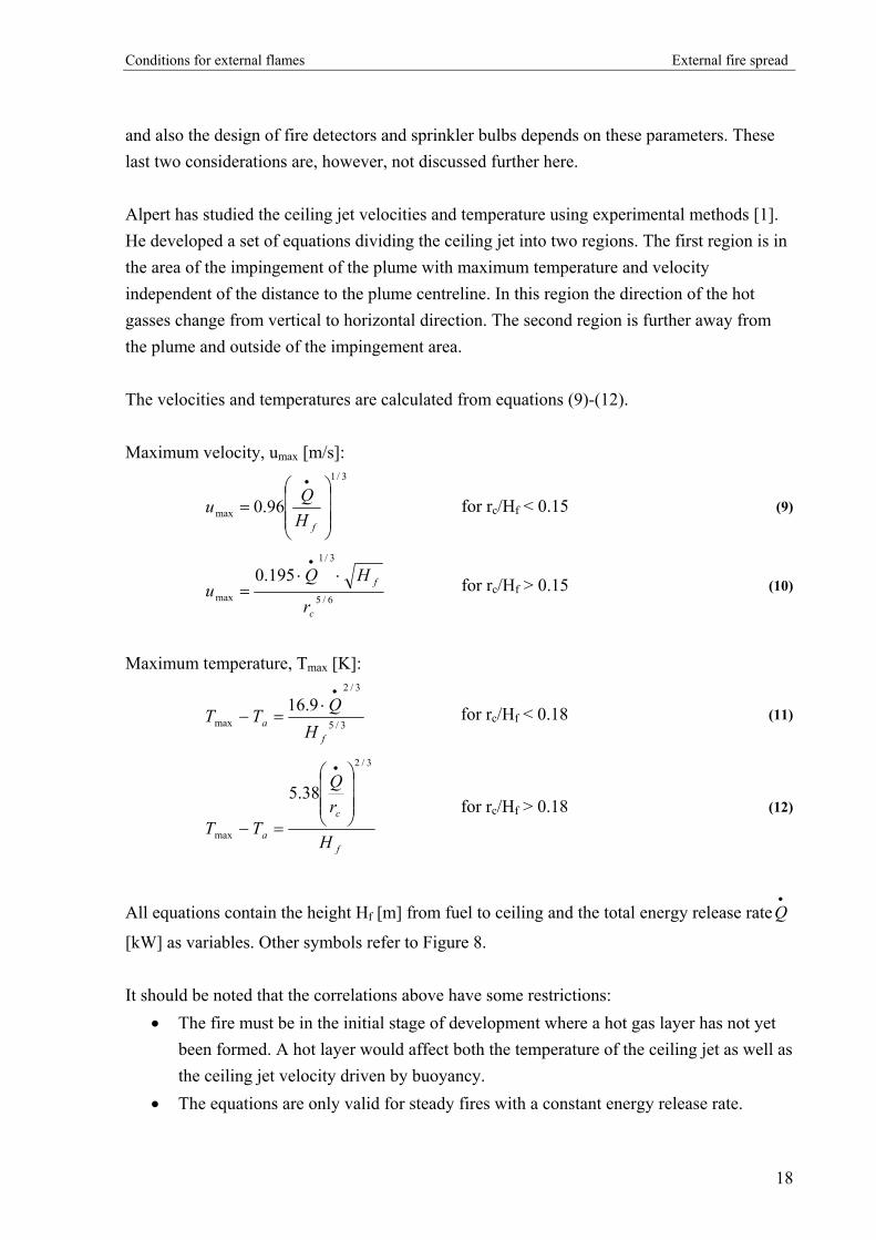
and also the design of fire detectors and sprinkler bulbs depends on these parameters. These last two considerations are, however, not discussed further here. Alpert has studied the ceiling jet velocities and temperature using experimental methods [1]. He developed a set of equations dividing the ceiling jet into two regions. The first region is in the area of the impingement of the plume with maximum temperature and velocity independent of the distance to the plume centreline. In this region the direction of the hot gasses change from vertical to horizontal direction. The second region is further away from the plume and outside of the impingement area. The velocities and temperatures are calculated from equations (9)-(12). Maximum velocity, umax [m/s]:
3/1
max 96.0
=
•
fHQu for rc/Hf < 0.15 (9)
6/5
3/1
max
195.0
c
f
r
HQu
⋅⋅=
•
for rc/Hf > 0.15 (10)
Maximum temperature, Tmax [K]:
3/5
3/2
max9.16
fa H
QTT•
⋅=− for rc/Hf < 0.18 (11)
f
c
a H
rQ
TT
3/2
max
38.5
=−
•
for rc/Hf > 0.18 (12)
All equations contain the height Hf [m] from fuel to ceiling and the total energy release rateQ
[kW] as variables. Other symbols refer to Figure 8.
•
It should be noted that the correlations above have some restrictions:
• The fire must be in the initial stage of development where a hot gas layer has not yet been formed. A hot layer would affect both the temperature of the ceiling jet as well as the ceiling jet velocity driven by buoyancy.
• The equations are only valid for steady fires with a constant energy release rate.
18

Conditions for external flames External fire spread
• The location of the fuel is assumed far from the enclosure walls so that the walls do not influence the combustion process.
• A flat and smooth horizontal ceiling is assumed, i.e. no inclination or ceiling beams. Furthermore, it is worth noting that the equations are only valid for a weak plume, which is defined as the case where the flame height is “much smaller” than the height Hf. Alpert did not clarify the ratio ”much smaller” in 1972, but mentioned that research was going on investigating ceiling jets for larger plumes. Later research has suggested a correlation for the temperature of a ceiling jet produced by a “strong plume” [14]. The term “strong plume” is here used for the case where the flame height in the plume is approaching the height Hf. The temperature can be estimated by equation (13).
−−
=∆∆
−
br
br
TT cc
p
161.1exp92.11
for 1≤ rc/b ≤ 40 (13)
∆T: excess temperature of hot gasses in ceiling jet, Tmax - Ta [K]
∆Tp: excess temperature on the plume centreline at ceiling level, Tp - Ta [K] b: plume radius at ceiling level [m] rc: radial position of consideration [m] (refer to Figure 8)
Heskestad was one of the researchers behind the latter correlation for temperature estimation. From his earlier research and development of plume models he derived equations for calculation of the plume temperature and radius. These equations can be used for determining ∆Tp and b in equation (13) and are found in the literature [27]. As can be seen from equation (13) the plume radius uses a normalized length scale instead of the height from fuel to ceiling. However, this does not mean that the temperature of the ceiling jet is independent of the room geometry in this method, since the room height is used in the determination of b. From the study of literature on ceiling jets it has become clear that in order to make any estimations on velocity and temperature of the ceiling jet the amount of energy release from the fire must be determined.
19
Conditions for external flames External fire spread
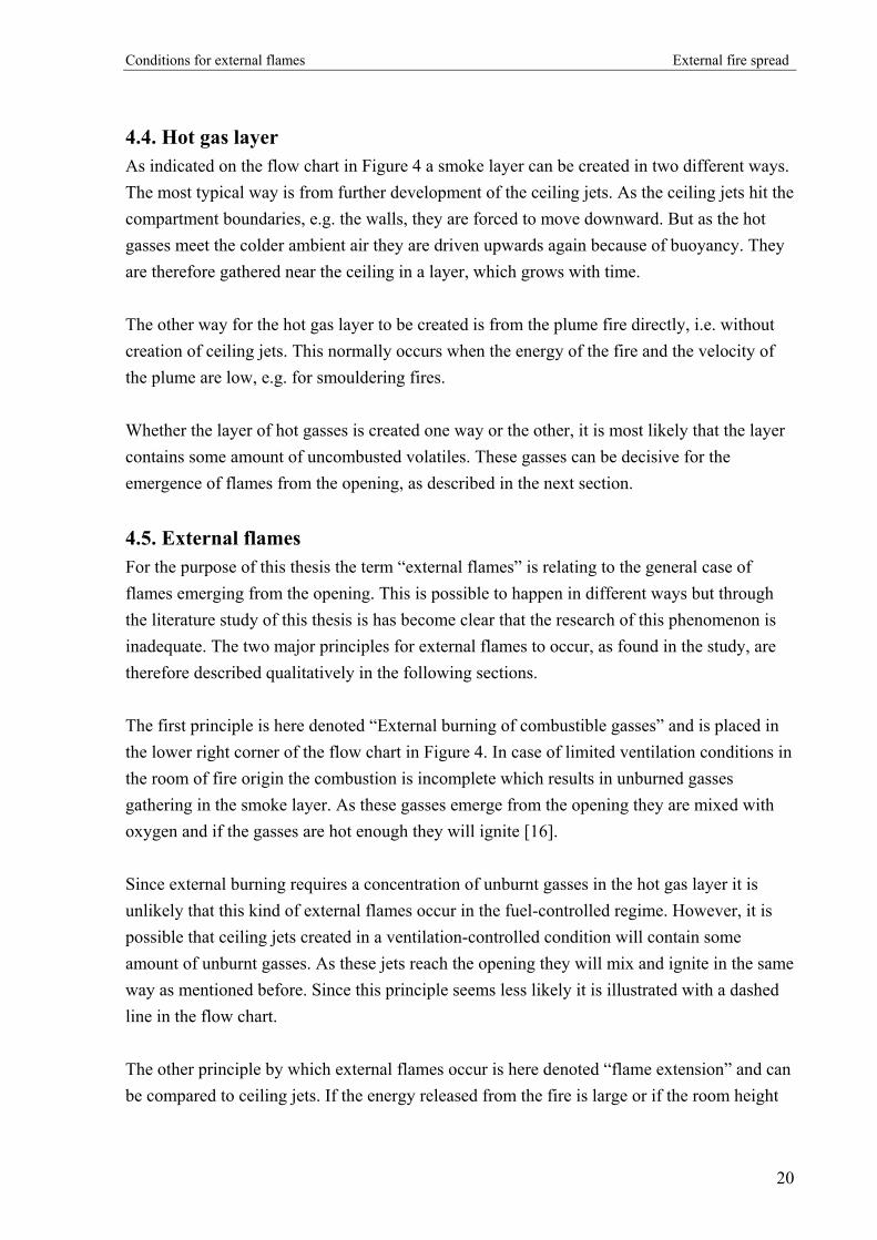
4.4. Hot gas layer As indicated on the flow chart in Figure 4 a smoke layer can be created in two different ways. The most typical way is from further development of the ceiling jets. As the ceiling jets hit the compartment boundaries, e.g. the walls, they are forced to move downward. But as the hot gasses meet the colder ambient air they are driven upwards again because of buoyancy. They are therefore gathered near the ceiling in a layer, which grows with time. The other way for the hot gas layer to be created is from the plume fire directly, i.e. without creation of ceiling jets. This normally occurs when the energy of the fire and the velocity of the plume are low, e.g. for smouldering fires. Whether the layer of hot gasses is created one way or the other, it is most likely that the layer contains some amount of uncombusted volatiles. These gasses can be decisive for the emergence of flames from the opening, as described in the next section.
4.5. External flames For the purpose of this thesis the term “external flames” is relating to the general case of flames emerging from the opening. This is possible to happen in different ways but through the literature study of this thesis is has become clear that the research of this phenomenon is inadequate. The two major principles for external flames to occur, as found in the study, are therefore described qualitatively in the following sections. The first principle is here denoted “External burning of combustible gasses” and is placed in the lower right corner of the flow chart in Figure 4. In case of limited ventilation conditions in the room of fire origin the combustion is incomplete which results in unburned gasses gathering in the smoke layer. As these gasses emerge from the opening they are mixed with oxygen and if the gasses are hot enough they will ignite [16]. Since external burning requires a concentration of unburnt gasses in the hot gas layer it is unlikely that this kind of external flames occur in the fuel-controlled regime. However, it is possible that ceiling jets created in a ventilation-controlled condition will contain some amount of unburnt gasses. As these jets reach the opening they will mix and ignite in the same way as mentioned before. Since this principle seems less likely it is illustrated with a dashed line in the flow chart. The other principle by which external flames occur is here denoted “flame extension” and can be compared to ceiling jets. If the energy released from the fire is large or if the room height
20

Conditions for external flames External fire spread
is small, flames from the plume can deflect at the ceiling. The flame extensions then spread along the ceiling and will eventually emerge from the room opening. If the top of the opening is at the same level as the ceiling, the flame extensions are not obstructed and will have free pass to emerge. This means that external flames can occur even for smaller fires or at an early stage of a fire, e.g. in the fuel-controlled regime [16]. Since the principles of the two major types of external flames are very different it is likely that the behaviour and characteristics of the emerging flames are also different. Further research could most certainly establish major differences in e.g. the temperatures and trajectories of the two flame types. Furthermore, in case of external burning more information is needed on the necessary temperature and mixture for the gasses to ignite.
21

Behaviour and dimensions of external flames and plumes External fire spread
5. Behaviour and dimensions of external flames and plumes
5.1. Plume properties This chapter discusses factors from the general fire theory that can be attached to plumes appearing outside an opening in a building façade.
5.1.1. Free or enclosed burning It is unclear whether external flames have the properties of flames burning freely or flames in an enclosed fire. The ventilation conditions indicate an open burning except from the presence of a wall along one side of the plume. However, in the case of flames ejecting from an opening they set off in the compartment and continues in the open. In the case of fuel-rich gasses leaving the room, the gasses are pre-heated and may be mixed with a certain amount of air from the fire room. Furthermore, the heat flux from the combustion processes will not contribute much to the evolution and maintenance of the fire origin. Only the part of the plume located just outside the opening and in the room of fire origin will radiate back to the fuel and thereby vapourize combustible gasses. This uncertainty in ventilation conditions makes it difficult to predict the behaviour and progress of the plume. Empirical correlations have been developed through test work and will be presented later. Following is a description of the most important general mechanisms related to external plumes. Due to the severe nature of the conditions leading to external plumes the flames are presumed to be turbulent and diffusion oxidized.
5.1.2. Flame regions McCaffrey divides the plume in three regions, as illustrated in Figure 9; the continuous flame region with an accelerating flow velocity, the intermittent flame region with a near-constant velocity and the buoyant plume where velocity is increasing [27]. In the following, only the first two regions will be considered since the temperature in the last region is assumed insufficient to ignite common materials in the building types and fires considered. However, the hot air in the buoyant plume can play a minor role by pre-heating the construction parts that are exposed by the intermittent or continuous flame regions at a later stage.
22
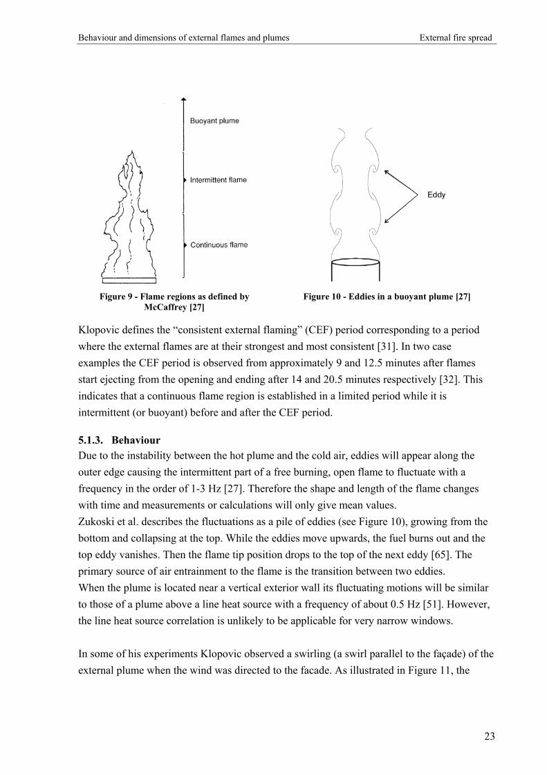
Behaviour and dimensions of external flames and plumes External fire spread
Figure 9 - Flame regions as defined by
McCaffrey [27] Figure 10 - Eddies in a buoyant plume [27]
Klopovic defines the “consistent external flaming” (CEF) period corresponding to a period where the external flames are at their strongest and most consistent [31]. In two case examples the CEF period is observed from approximately 9 and 12.5 minutes after flames start ejecting from the opening and ending after 14 and 20.5 minutes respectively [32]. This indicates that a continuous flame region is established in a limited period while it is intermittent (or buoyant) before and after the CEF period.
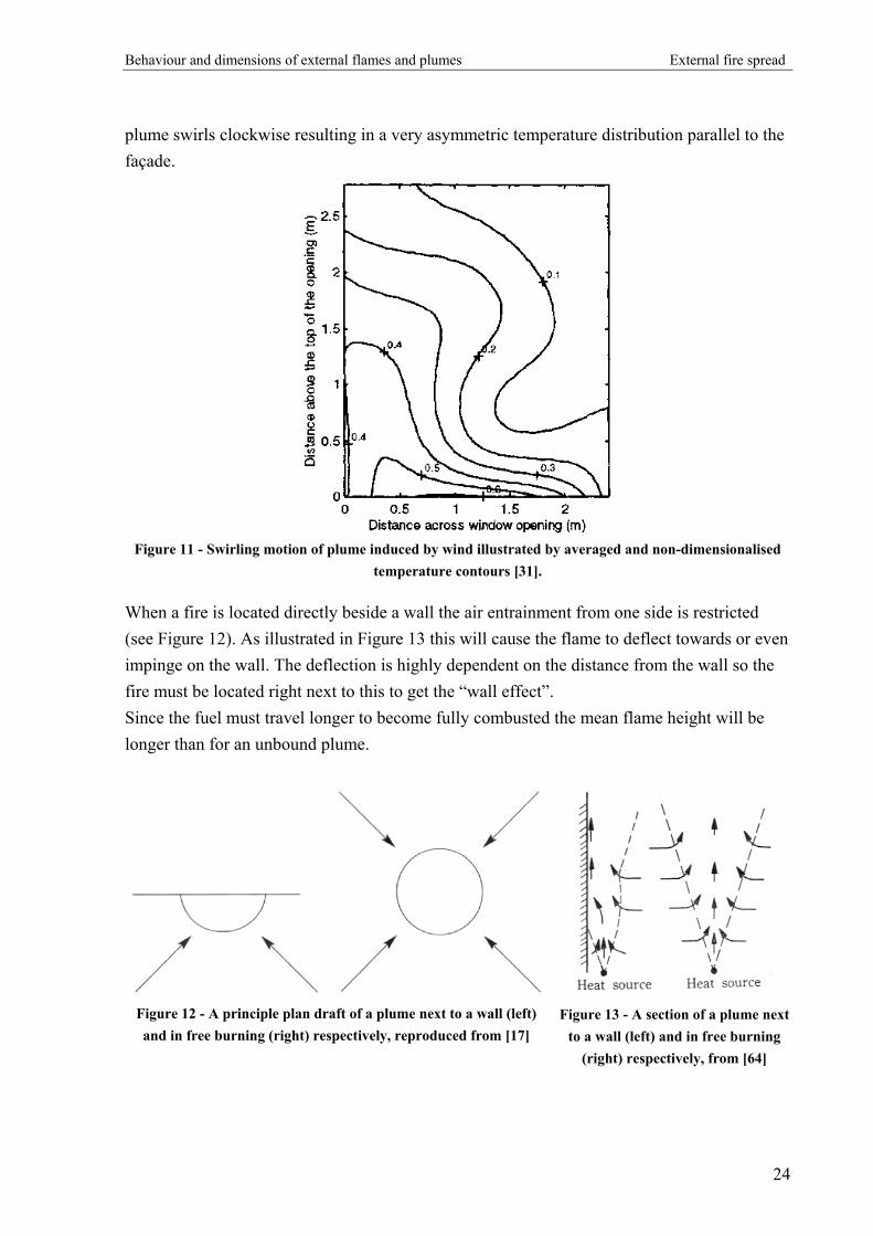
5.1.3. Behaviour Due to the instability between the hot plume and the cold air, eddies will appear along the outer edge causing the intermittent part of a free burning, open flame to fluctuate with a frequency in the order of 1-3 Hz [27]. Therefore the shape and length of the flame changes with time and measurements or calculations will only give mean values. Zukoski et al. describes the fluctuations as a pile of eddies (see Figure 10), growing from the bottom and collapsing at the top. While the eddies move upwards, the fuel burns out and the top eddy vanishes. Then the flame tip position drops to the top of the next eddy [65]. The primary source of air entrainment to the flame is the transition between two eddies. When the plume is located near a vertical exterior wall its fluctuating motions will be similar to those of a plume above a line heat source with a frequency of about 0.5 Hz [51]. However, the line heat source correlation is unlikely to be applicable for very narrow windows. In some of his experiments Klopovic observed a swirling (a swirl parallel to the façade) of the external plume when the wind was directed to the facade. As illustrated in Figure 11, the
23
Behaviour and dimensions of external flames and plumes External fire spread
plume swirls clockwise resulting in a very asymmetric temperature distribution parallel to the façade.
Figure 11 - Swirling motion of plume induced by wind illustrated by averaged and non-dimensionalised
temperature contours [31].
When a fire is located directly beside a wall the air entrainment from one side is restricted (see Figure 12). As illustrated in Figure 13 this will cause the flame to deflect towards or even impinge on the wall. The deflection is highly dependent on the distance from the wall so the fire must be located right next to this to get the “wall effect”. Since the fuel must travel longer to become fully combusted the mean flame height will be longer than for an unbound plume.
Figure 12 - A principle plan draft of a plume next to a wall (left) and in free burning (right) respectively, reproduced from [17]
Figure 13 - A section of a plume next
to a wall (left) and in free burning (right) respectively, from [64]
24

Behaviour and dimensions of external flames and plumes External fire spread
The plume impingement is confirmed by several references on external plumes, both experimental and numerical. Moreover, it has been shown that even with rather wide horizontal projections the plume will re-attach to the wall [45]. The distance from plume to wall is discussed later. An important topic that has only been evaluated by few research projects is the behaviour of the plume when it passes the opening to the compartment above the fire room. As early as 1960 Ashton and Malhotra pointed out that the building codes (UK) assumed an incorrect behaviour of flames ejecting from openings [2]. Figure 14 illustrates their findings. The sketches left and middle shows the assumed behaviour with and without the spandrel required in the building codes. The right sketch illustrates the actual flame behaviour observed in experiments.
Figure 14 - Assumed (left and middle) and actual (right) flame behaviour [2].
The conclusion is that the flames enter the room above despite a spandrel with the required dimensions being deployed. Satoh et al. made a two-dimensional numerical study on nine different cases of external plume evolution of which one had an open compartment immediately above the fire room [51]. When the plume passed the compartment it was ejected away from the lower part of the opening while some of the plume was entering the upper part, as illustrated in Figure 15.
25

Behaviour and dimensions of external flames and plumes External fire spread
Figure 15 - 2D isotherms showing hot air entering the room above the fire [51].
The two-dimensional studies correspond to situations with infinitely wide windows, but the phenomenon described is likely to occur in real building configurations. The presence of wind around or through the building will have a major influence by either increasing or decreasing the amount of hot air entering the compartment. This needs to be investigated in future studies.
5.2. Dimensions of external flames Most of the following relations and equations distinguish between a situation with a wall above the window and a “no-wall” situation (see illustration in Appendix 2). Also two conditions of draft are considered; a natural draft and a forced draft induced either by a wind blowing through the building or by a fire elsewhere in the building. The use of most of the expressions for estimation of flame dimensions are demonstrated in a case example in Appendix 3. Figure 16 illustrates notations used.
26

Behaviour and dimensions of external flames and plumes External fire spread
Figure 16 - Notations used in external flame estimations.
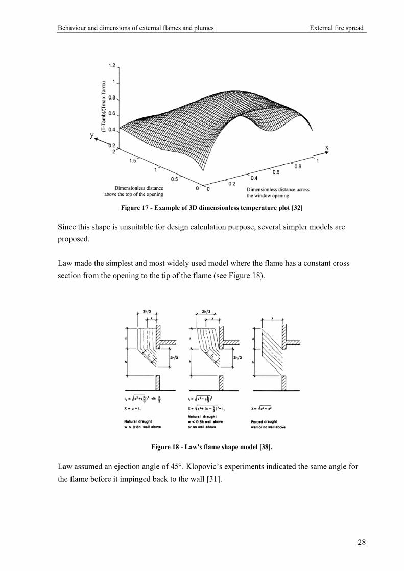
5.2.1. The flame shape A generalized and simplified flame shape definition is a vital basis for flame dimension calculations without CFD1 modelling. The boundary is mostly defined as a surface with a certain chosen temperature, mainly 813 K as discussed in the paragraph defining the flame tip. When averaged over time, the real external flame (and plume) tends to have the shape of “a water drop cut vertically in half” where the façade does the cutting. Klopovic illustrated this by making 3D dimensionless time averaged temperature plots like the one in Figure 17. The surface in the xy-plane represents the façade above the opening.
1 CFD: Computational Fluid Dynamics
27
Behaviour and dimensions of external flames and plumes External fire spread
y
Figure 17 - Example of 3D dimensionless temperature plot [32]
Since this shape is unsuitable for design calculation purpose, several simpler models are proposed. Law made the simplest and most widely used model where the flame has a constant cross section from the opening to the tip of the flame (see Figure 18).
Figure 18 - Law's flame shape model [38].
Law assumed an ejection angle of 45°. Klopovic’s experiments indicated the same angle for the flame before it impinged back to the wall [31].
28

Behaviour and dimensions of external flames and plumes External fire spread
In order to calculate heat transfer to the façade, Oleszkiewicz assumed a slightly more realistic but still simple triangular flame model. In Figure 19 this is illustrated along with the “half drop” or “belly” which it was called by Klopovic.
Figure 19 - Scematic side view of Oleszkiewicz triangular flame and Klopovic's "belly" plume [32].
5.2.2. Definition of flame tip
The flame tip is widely defined as the point where the temperature difference is 520 K i.e. the flame temperature is 813 K when the ambient temperature is 293 K. Most references refer to the basically unchanged properties of steel until a temperature of 813 K (e.g. [52] and [38]). No reference defines “unchanged”. In the Danish Code of Practice for the Structural Use of Steel [15] some relative steel properties are given as a function of temperature. Figure 20 illustrates the yield stress in normal and simplified calculations and the modulus of elasticity at various steel temperatures.
0
0,1
0,2
0,3
0,4
0,5
0,6
0,7
0,8
0,9
1
200 400 600 800 1000 1200 1400
Steel temperature [K]
Rel
ativ
e st
reng
th [-
]
Yield stress
Yield stress -simplified calculationsModulus of elasticity
813 K
Figure 20 - Steel properties as a function of material temperature, produced from [15]
29

Behaviour and dimensions of external flames and plumes External fire spread
At 813 K the yield stress is about 65 % of the cold value while the yield stress used for “simplified calculations” and the modulus of elasticity are reduced to half the value of the cold situation. These are considerable reductions, even though, the Danish safety factors used for load on constructions are lower in the fire situation design than for the “normal load” design. Furthermore, the flame tip definition is used in references that have nothing to do with steel structures. Some authors simply adopted the definition from previous references. In addition, several references (e.g. [40]) determine that 813 K corresponds to the temperature where the flame loses its luminous – and thereby visible – character. This may be the main reason for the widely used flame tip definition, since the top of the flame can easily be observed by eye or video during experiments. Since the expressions for estimation of external flame properties are not validated for other temperatures, the above definition will be used in this thesis. Consequently, when using the following equations for estimation of flame dimensions, a qualified judgement should be made of whether the flame tip definition is appropriate. When the risk of external fire spread or constructions of concrete or timber are considered much lower temperatures may be critical.
5.2.3. Flame height A general correlation for the situation where no wall is present above the window is explained by Law [37] and later simplified by Quintiere [48]:
Θ⋅
=+= 0rBHzl of (14)
lf: flame height [m] z: height of flame tip above window [m]
Ho: window height [m]
r0: equivalent window radius π⋅⋅
=2
hw [m]
The dimensionless temperature Θ is given by
322
2
350
gcTQ
rT
a
/z
ρ
•
⋅∆=Θ
(15)
B is a dimensionless number given by [37]:
30

Behaviour and dimensions of external flames and plumes External fire spread
31
2
22
618/
al TC
gcT.B
⋅⋅
⋅⋅⋅∆⋅=
πρ
(16)
∆Tz: effective mean temperature rise at z [K] ∆Tl: effective mean temperature rise at the flame tip [K]
Q : energy release rate•
2 [kW]
c: specific heat of gasses [kJ/kgK] ρ: density of gasses [kg/m3] g: gravity [m/s2] C: effective heat of combustion [kJ/kg] Ta: ambient temperature [K] It can be assumed that B ≅ 2 in the flame region. For the region above the flames a value of B ≅ 1.3 is more reasonable [37]. When B = 2 and typical values (Tz = 290 K, ρ = 0.45 kg/m3 at 773 K, cp = 1.0 kJ/kg K, g = 9.81 m/s2) and a flame tip temperature of 810 K (∆Tl = 520 K) are chosen [48], equation (15) becomes (with natural draft):
32
350998 /
/
Q
r.
•=Θ (17)
Noting that r0 = ½D gives 32
0320
/
of DQ.Hzl
=+=
•
(18)
D: equivalent opening diameter [m] Apparently Quintiere gives no correlation for the forced draft situation. Using the temperature-controlled definition of the flame tip (813 K) Law gives a correlation between the research by Yokoi, Webster et al. and Seigel for the “no-wall” situation [38]. 2 Klopovic showed that the heat loss through the opening is more accurate. In his experiments the heat release rate through the opening was 27 % of the total heat release in the room [Klopovic, 2001/II].
31
Behaviour and dimensions of external flames and plumes External fire spread
With natural draft: 32
812
/
oof w
m.Hzl
=+=
•
(19)
With forced draft:
⋅
=+=
•
21
4301916 /
o
.
wof A
mu
.Hzl (20)
: burning rate [kg/s] •
m wo: opening width [m] uw: wind velocity [m/s] Ao: area of openings from which flames emerge [m2] None of the literature considered in this thesis offers an evaluation as to whether the “no-wall” flame length expression can be used uncorrected when a wall is present above the opening. In [38] the equations (19) and (20) are presented without distinguishing between the two building configurations.
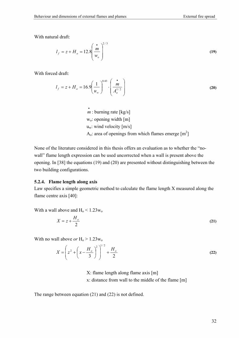
5.2.4. Flame length along axis Law specifies a simple geometric method to calculate the flame length X measured along the flame centre axis [40]: With a wall above and Ho < 1.23wo
2
oHzX += (21)
With no wall above or Ho > 1.23wo
23
2122 o
/
o HHxzX +
−+= (22)
X: flame length along flame axis [m] x: distance from wall to the middle of the flame [m] The range between equation (21) and (22) is not defined.
32

Behaviour and dimensions of external flames and plumes External fire spread
5.2.5. Distance from wall to flame When a wall is present above the opening Law recommends the following expression for the distance x from the wall to the middle of the flame tip with natural draft [38]:
⋅⋅= 530
14540 .o nH.x (23)
n: width-to-height opening ratio = 2w/h [-]
The distance x is dependent on the opening dimensions expressed by n. An increasing value of n gives a decreasing value of x. In other words, flames ejecting from wide openings have a smaller projection as long as a wall is present above.
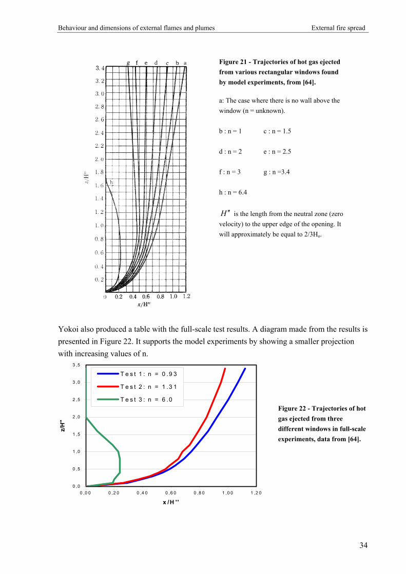
The tendency of plumes inclining to a wall is known from the general plume theory and is described in a former chapter. Yokoi proved a connection between the opening shape n and the projection of external plumes towards the wall above (see Figure 21). Note that Yokoi did not use the flame tip definition in his experiments. He examined the trajectory of the plume by tracing the temperature distribution.
33
Behaviour and dimensions of external flames and plumes External fire spread
Figure 21 - Trajectories of hot gas ejected from various rectangular windows found by model experiments, from [64].
a: The case where there is no wall above the window (n = unknown). b : n = 1 c : n = 1.5 d : n = 2 e : n = 2.5 f : n = 3 g : n =3.4 h : n = 6.4
H ′′ is the length from the neutral zone (zero velocity) to the upper edge of the opening. It will approximately be equal to 2/3Ho.
Yokoi also produced a table with the full-scale test results. A diagram made from the results is presented in Figure 22. It supports the model experiments by showing a smaller projection with increasing values of n.
0 ,0
0 ,5
1 ,0
1 ,5
2 ,0
2 ,5
3 ,0
3 ,5
0 ,0 0 0 ,2 0 0 ,4 0 0 ,6 0 0 ,8 0 1 ,0 0 1 ,2 0
x /H ''
z/H
''
T e s t 1 : n = 0 .9 3
T e s t 2 : n = 1 .3 1
T e s t 3 : n = 6 .0Figure 22 - Trajectories of hot gas ejected from three different windows in full-scale experiments, data from [64].
34

Behaviour and dimensions of external flames and plumes External fire spread
In the no-wall situation with natural draft Law recommends Yokoi’s relationship since no other data is available: 31
600/
oo H
zH.x
⋅⋅= (24)
In this situation x is independent of the window dimensions.
With a forced draft there is no difference in the wall/no-wall conditions but similar to the flame length correlation it is dependent on the wind velocity [38]:
)Hz(Hu
.x o
.
o
w +⋅
⋅=
2202
6050 (25)
No reference found indicates whether the flame will be “squeezed” when the flame inclines to the wall. Thus, since x is the distance to the middle of the flame it will be assumed that x cannot be less than half the flame thickness.
5.2.6. Flame width Measurements at the Underwriters’ Laboratories suggest that the maximum width of the emerging flame will be little different from the window width in case of natural draft while a propagation of 11° from each side of the window should be expected in case of forced draft, see Figure 23 [38]. Natural draft: oz ww ≅ (26)
Forced draft: ooz w.ww ⋅+≅ 40 (27)
Figure 23 - Simplified flame width notation [38].
35

Behaviour and dimensions of external flames and plumes External fire spread
These flame width estimations are contrary to the observations during Klopovic’s full-scale experiments. They suggest that the width of the plume is 0.5 m wider than the opening on both sides during “no-through-draft” (corresponding to Law’s “natural draft”) and a plume width corresponding to the opening width during “through-draft” (corresponding to Law’s “forced draft”) [31]. This is supported by Bullen and Thomas, who observed a considerably widening of flames ejecting from narrow openings during their experiments with non-cellulosic fuels [10]. The suggestions are based on real, well-documented fire experiments so it is not possible in this thesis to judge, which one is most correct.
5.2.7. Flame thickness In relation to radiation calculations it will be relevant to estimate the thickness of the ejected flames. Law proposes a thickness of 2/3 of the window height in case of natural draft referring to the general location of the neutral axis [40]. In case of forced draft the flame thickness is defined as the full window height since no “inflow zone” is needed. In Klopovic’s experiments with through-draft, the wind was insufficient for the flame thickness to fit Law’s forced draft expression and the natural draft was found to fit much better. In real design both situations should be calculated and the worst scenario chosen. To give a less overestimated flame thickness, Oleszkiewicz’s triangular flame shape is useful. It assumes a linear decrease in thickness from the top of the opening in the room of fire origin (where Law’s expression is used) to the tip of the flame (where the thickness is zero). This must be used with caution, since a zero thickness gives no radiation. The flame thickness is assumed independent of the presence of a wall above the opening.
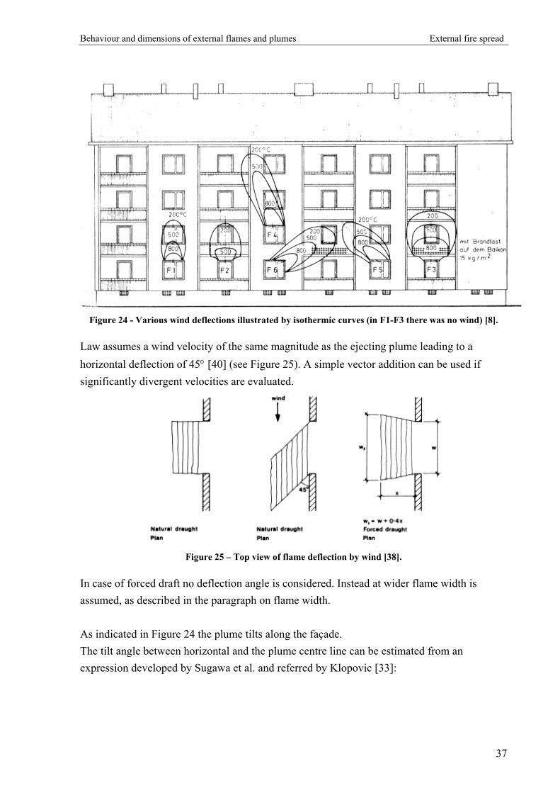
5.2.8. Deflection by wind When a wind is blowing parallel to the building façade the flame will deflect horizontally to the side of the window. This may affect openings in the adjacent compartment or compartments on a higher level displaced from the fire compartment. This is illustrated in Figure 24 by Bechtold’s isothermal curves made from full-scale fire experiments.
36
Behaviour and dimensions of external flames and plumes External fire spread
Figure 24 - Various wind deflections illustrated by isothermic curves (in F1-F3 there was no wind) [8].
Law assumes a wind velocity of the same magnitude as the ejecting plume leading to a horizontal deflection of 45° [40] (see Figure 25). A simple vector addition can be used if significantly divergent velocities are evaluated.
Figure 25 – Top view of flame deflection by wind [38].
In case of forced draft no deflection angle is considered. Instead at wider flame width is assumed, as described in the paragraph on flame width. As indicated in Figure 24 the plume tilts along the façade. The tilt angle between horizontal and the plume centre line can be estimated from an expression developed by Sugawa et al. and referred by Klopovic [33]:
37

Behaviour and dimensions of external flames and plumes External fire spread
31 /
o
op
w
wH
u
usin
=ϕ
(28)
The plume velocity is calculated by
oaaap wcT
gQu⋅⋅⋅
⋅=
•
ρ (29)
ϕ: tilt angle [°] uw: wind velocity [m/s] up: plume velocity [m/s]
: heat release rate [kW] •
Q
ρa: density of ambient air [kg/m3] Ta: temperature of ambient air [K] ca: specific heat of ambient air [kJ/kg⋅K] Yokoi observed plume velocities (measured at the opening) in the range of 4-8 m/s in his four full-scale experiments.
38
Flame temperatures External fire spread
6. Flame temperatures
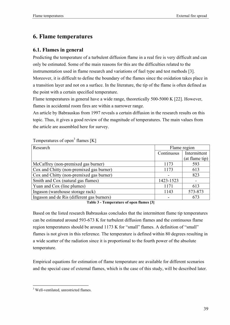
6.1. Flames in general Predicting the temperature of a turbulent diffusion flame in a real fire is very difficult and can only be estimated. Some of the main reasons for this are the difficulties related to the instrumentation used in flame research and variations of fuel type and test methods [3]. Moreover, it is difficult to define the boundary of the flames since the oxidation takes place in a transition layer and not on a surface. In the literature, the tip of the flame is often defined as the point with a certain specified temperature. Flame temperatures in general have a wide range, theoretically 500-5000 K [22]. However, flames in accidental room fires are within a narrower range. An article by Babrauskas from 1997 reveals a certain diffusion in the research results on this topic. Thus, it gives a good review of the magnitude of temperatures. The main values from the article are assembled here for survey. Temperatures of open3 flames [K]
Flame region Research Continuous Intermittent
(at flame tip)McCaffrey (non-premixed gas burner) 1173 593 Cox and Chitty (non-premixed gas burner) 1173 613 Cox and Chitty (non-premixed gas burner) - 823 Smith and Cox (natural gas flames) 1423-1523 - Yuan and Cox (line plumes) 1171 613 Ingason (warehouse storage rack) 1143 573-873 Ingason and de Ris (different gas burners) - 673
Table 3 - Temperature of open flames [3]
Based on the listed research Babrauskas concludes that the intermittent flame tip temperatures can be estimated around 593-673 K for turbulent diffusion flames and the continuous flame region temperatures should be around 1173 K for “small” flames. A definition of “small” flames is not given in this reference. The temperature is defined within 80 degrees resulting in a wide scatter of the radiation since it is proportional to the fourth power of the absolute temperature. Empirical equations for estimation of flame temperature are available for different scenarios and the special case of external flames, which is the case of this study, will be described later.
3 Well-ventilated, unrestricted flames.
39
Flame temperatures External fire spread
Several methods have been developed to predict the temperature in a fire plume and the following are the most commonly used. These methods do not distinguish the flame from the current of hot gasses, in other words, no flame (tip) is defined. They may be used to find an approximate flame height if a certain flame tip temperature is defined. The Heskestad Plume is described by the convective part of the heat release rate and a virtual origin calculated by the total heat release rate and diameter of the fire [27]. The temperature rise in the fire plume under normal conditions and with an ambient air temperature of 293 K is: 35
0
52
25
/
f
/
c
)zz(Q
T
−⋅=∆
•
(30)
f
/
D.Q.z ⋅−⋅=•
021083052
0
z0: Location of virtual origin [m] ∆T: Temperature increase [K]
Q : convective part of heat release rate [kW] c
•
Q : total heat release rate [kW] •
zf: height from floor level [m] z0: height of virtual origin [m] Df: diameter of the fire [m] The McCaffrey Plume does not use the virtual origin but distinguishes between the three plume regions by introducing some constants calculated from the height and heat release rate. The temperature rise equations for the three regions under normal conditions and an ambient air temperature of 293 K are derived here for comparison [27].
Continuous region
K 853=∆T for < 0.08 52 /
f Q/z•
(31)
40

Flame temperatures External fire spread
Intermittent region
⋅=∆
•
f
/
zQ.T
52
566 for 0.08 < <
0.2
52 /
f Q/z•
(32)
Buoyant plume 3552
322
/
f
/
zQ.T
⋅=∆
•⋅
for > 0.2 52 /
f Q/z• (33)
6.2. Temperature distribution in external flames When considering the radiant and convective heat flux from an external flame to an opening in the façade, the temperature distribution along the exposing flame surface is the most important factor, as described later in the chapter on heat transfer. The external temperature is proportional to the heat release rate and the temperature of the room of fire origin. Additionally, Bechtold showed that the external gas temperature followed the highest temperature in the room during the growth and fully developed stages while during the decay stage it followed the mean temperature of the room as illustrated in Figure 26. It is not clear how many experiments the curve is based on.
Figure 26 - Temperature development in fire room and in front of the façade [8].
Curve a: The highest temperature in the room of fire origin [°C].
Curve b: Mean temperature in the fire room [°C].
Curve c: Exterior temperature in a point at the height of the fire room ceiling, 60 cm from the façade [°C].
In the case of hot fuel-rich gasses pouring out through the opening, a certain temperature is needed for the oxidation to occur, i.e. under this temperature the gasses are not reactive. In the SFPE Handbook chapter 2-5, Gottuk and Lattimer state that the minimum reaction temperature is 850-900 K [16] but they do not describe how it varies with height and width.
41

Flame temperatures External fire spread
In real fires the temperature varies in all directions, as described by Klopovic. However, in the present thesis only differences with height and width are considered important. Most research on external flames assumes a constant temperature along the width of the opening. This is an acceptable approximation when the fire room opening and the exposed openings have the same width. If the exposed opening is significantly wider than the opening in the room of fire origin, the estimation is too high. Based on the work of Yokoi, Seigel and others, Law derived an expression of the vertical temperature distribution along the flame axis [37]: Natural draft
⋅−=
−−
•
m
wl.
TTTT o
a
az 027010
(34)
If the flame tip definition is Tz-Ta = 520 K
−
=−
•
m
wX.
TTo
a
02701
5200
Forced draft
⋅−=
−−
•
m
Al.
TTTT /
o
a
az21
0
02701 (35)
If the flame tip definition is Tz-Ta = 520 K
−
=−
•
m
AX.
TT/
o
a21
0
02701
520
Tz: temperature rise at distance l along the flame axis [K]
T0: flame temperature at opening [K] Ta: ambient temperature [K] l: distance along flame centre line [m] wo: opening width [m] X: centre line flame length [m]
42

Flame temperatures External fire spread
oo HkAm =•
[kg/s]
( )2
103601180WW
e.k . η−−=
HAA
o
T=η
Ao: opening area [m2] AT: area of enclosing surfaces minus Ao [m2] W1: width of compartment [m] W2: depth of compartment [m] Law remarks that for fires with natural draft the value of Tz can be higher than the temperature in the room of fire origin. This will be due to unburnt gasses escaping the compartment and burning outside. In equations (34) and (35) the empirical constant has a similar value of 0.027 but in a later reference [40] the constant in (35) has changed to 0.019 without any explanation. The difference from 0.027 to 0.019 is 30 % producing a 30 % higher flame temperature. The highest constant is chosen here since it is used in the best theoretically supported reference. Klopovic presented a slightly different expression for the temperature distribution for no-through-draft (based on Law’s expression) [33]:
⋅−=
−−
•
m
wl..
TTTT o
a
az 0318082900
(36)
It should be noted that Law’s expression was based on wood crib experiments in reduced scale fire rooms while Klopovic used real commercial furniture in a realistic building configuration. It is not possible in this thesis to evaluate whether Law or Klopovic gives the right answer. As illustrated in Figure 27, Law’s expression will be a conservative choice.
43

Flame temperatures External fire spread
0,00
0,10
0,20
0,30
0,40
0,50
0,60
0,70
0,80
0,90
1,00
0,00 5,00 10,00 15,00 20,00 25,00
lw/m [m2*kg/s]
(Tz-T
0)/(T
0-T a
) [-]
Law
Klopovic
Figure 27- Dimensionless temperature difference as a function of lw/R
6.3. Discussion Since temperature is the most important factor in calculation of heat transfer from flames and hot gasses, a precise method for estimation of the plume temperature is essential for the accuracy of risk calculations. Therefore, a temperature calculation should be made in every particular design or research. Only Law has presented a method for estimation of the temperature, but it is based on the 813 K flame tip definition and is not correlated for temperatures lower than this. In order to estimate the temperature distribution from the opening in the room of fire origin to the point of ambient air temperature, further research is needed. Experiments can reveal whether Law’s expression can be used for lower flame tip temperatures or they can give new, more general, expressions.
44

Heat transfer External fire spread
7. Heat transfer
Traditionally, the transfer of heat from one object to another can be described by ways of radiation and conduction. In the case where heat is transferred with a moving fluid as media the heat transfer is described as convection. For the purpose of this thesis the heat transfer from the external flame to the room above fire origin is of importance when considering fire spread. Due to the lack of heat-conducting materials between the flame and the building facades and since the contribution to heat transfer from conduction is generally small in building fires the conduction is neglected here.
7.1. Radiation Through the years a lot of research has been conducted investigating the radiant heat transfer in a fire. The literature concerning the subject is comprehensive and the fundamental principles are therefore well known. This section serves to present the basic concept and parameters concerning radiation. In addition some of the theories developed regarding external flames are discussed. The most fundamental method of determining the intensity of radiation emitted from a hot object, I, is by use of the following correlation [34]:
4TI ⋅⋅= σε (37)
I: intensity of radiation [W/m2] ε: emissivity (0 ≤ ε ≤ 1) [-]
σ: Stefan-Boltzmann constant = 5.67⋅10-8 W/(m2K4) T: the absolute temperature of the object [K]
7.1.1. Emissivity
The emissivity factor appears in the expression for the intensity of the radiation, equation (37), since no materials can be regarded as entirely black bodies. A black body would have the ability to emit all thermal energy from the surface, i.e. ε = 1, but instead all materials are considered as grey bodies using the emissivity factor. The emissivity from hot objects consisting of certain solid materials has been investigated and values of the emissivity factor can be found in the literature. A small selection is shown in Table 4.
45

Heat transfer External fire spread
Surface Emissivity - ε [-] Aluminium, polished 0.05 Steel, polished or galvanized 0.27 Glass 0.94 Bricks, plaster 0.93 Wood 0.94
Table 4 - Examples of emissivity for common building materials at normal temperature [26]
Most liquids and solids burn with a luminous and sooting flame. The light from the flame as well as the soot released as smoke at the tip of the flame is produced as a result of non-consumed carbon from incomplete combustion. All soot particles within the flame each act as individual grey or approximately black bodies and contribute to a resulting emission from the flame. The resulting emission will be continuous, and can be calculated as a function of the geometry of the flame. Law uses the following correlation [38]:
Lflame e ⋅−−= κε 1 (38)
εflame: emissivity from flame [-] κ: absorption coefficient [m-1] L: flame thickness [m] The relation between emissivity and flame thickness for chosen values of κ is shown graphically in Figure 28. The diagram is produced from equation (38).
46
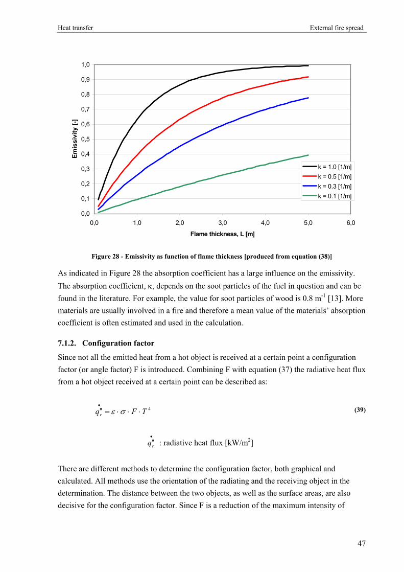
Heat transfer External fire spread
0,0
0,1
0,2
0,3
0,4
0,5
0,6
0,7
0,8
0,9
1,0
0,0 1,0 2,0 3,0 4,0 5,0 6,0
Flame thickness, L [m]
Emis
sivi
ty [-
]
k = 1.0 [1/m]k = 0.5 [1/m]k = 0.3 [1/m]k = 0.1 [1/m]
Figure 28 - Emissivity as function of flame thickness [produced from equation (38)]
As indicated in Figure 28 the absorption coefficient has a large influence on the emissivity. The absorption coefficient, κ, depends on the soot particles of the fuel in question and can be found in the literature. For example, the value for soot particles of wood is 0.8 m-1 [13]. More materials are usually involved in a fire and therefore a mean value of the materials’ absorption coefficient is often estimated and used in the calculation.
7.1.2. Configuration factor
Since not all the emitted heat from a hot object is received at a certain point a configuration factor (or angle factor) F is introduced. Combining F with equation (37) the radiative heat flux from a hot object received at a certain point can be described as:
4TFqr ⋅⋅⋅=′′•
σε (39)
: radiative heat flux [kW/m•′′rq 2]
There are different methods to determine the configuration factor, both graphical and calculated. All methods use the orientation of the radiating and the receiving object in the determination. The distance between the two objects, as well as the surface areas, are also decisive for the configuration factor. Since F is a reduction of the maximum intensity of
47

Heat transfer External fire spread
radiation from a hot object described by equation (37) the value must always be less than or equal to 1. As an example of F a configuration of the radiant interchange between an infinitesimal area dA1 and a finite surface A2 is considered. This is illustrated in Figure 29.
Figure 29 - Radiation between an infinitesimal area and a finite surface [13]
In this situation a distinction must be made between the two directions of emission, i.e. radiation from dA1 to A2 or vice versa. Here, the radiation from the finite surface to the infinitesimal area is considered. The resulting configuration factor, , can be calculated
from: 12 dAAF →
20
221
2
12
12
coscosdA
RAdA
FA
dAA ⋅⋅⋅
= ∫→ πββ
(40)
: configuration factor [-]
12 dAAF →
R: distance between radiator and receiver [m] dA1: area of infinitesimal receiver [m2]
A2: area of radiator [m2] The angles β1 and β2 are illustrated in Figure 29.
48

Heat transfer External fire spread
Similar correlations like equation (40) can be found for configuration factors corresponding to the radiation between two surfaces as well as for two infinitesimal areas or points [54]. Likewise, it is possible to determine the configuration factor from graphs and tables in the literature for different configurations.
7.1.3. Radiation from external flames
One of the most studied issues in terms of radiation from flames emerging from openings is the value of the emissivity. Law suggested an estimated value for the absorption coefficient of κ = 0.30 m-1 [38]. This value is derived from an analysis of experiments conducted by Heselden in Borehamwood in 1966, which included measurements of the heat flux above an opening in an enclosure fire. By plotting the measured values against the product of σ and T4 (refer to equation (37)), the plotted values could be approximated by a straight line. The slope of the line represents the value of ε and can be used for determination of the absorption coefficient by use of equation (38). This operation does not take into account the effect of convective heat transfer since this was assumed very small compared to radiation. The method described above for flames emerging from openings is often used for estimation of radiation from flames in general. However, some researchers are more reluctant to use the method. Drysdale suggested that the method should only be used in small fires with a flame thickness of 1 m or less [17]. Quintiere agreed in a distinction of fires but suggests the limit to be at 2 m. For larger flames an emissivity equal to 1 should be assumed in stead, i.e. black body behaviour [47]. According to Drysdale the simple calculation of ε assumes that the temperature and soot concentration of the flames being uniform. Since this is not the case in larger fires the use of equation (38) is invalid. Quintiere adds that when a fire grows to be very large the soot produced is likely to obscure the flame and reduce the radiation to the surroundings. This statement has, however, not been proved in the literature studied. It should be noted that neither Drysdale nor Quintiere substantiate the choice of limit between small and large fires. The values are most likely inferred from experimental work but such tests are not mentioned. The difference between the calculation of ε by use of an absorption coefficient of 0.30 m-1 and the approximation of ε = 1 for larger fires is clearly seen in Figure 28. E.g., the value for ε for L = 1 m and κ = 0.3 is a little less than 0.3.
49

Heat transfer External fire spread
When considering the emissivity from flames a geometrical model of the flame is chosen. The model can be in the shape of e.g. a cylinder and the choice of model is decisive for some of the characteristic dimensions of the flame. The cylindrical model is often used for idealization of the flame, since the thickness of the flame is constant with height (refer to Figure 30). In the calculation of the emissivity, by use of equation (38), this also gives a constant value. But other researchers, like Oleszkiewicz (refer to chapter 5.2), believe that the emissivity should decrease with height and are therefore more inclined to use a triangular shape model. This means that the flame thickness and thereby the emissivity decreases linearly up through the flame. Equation (38) then becomes: )(1)( zL
flame ez ⋅−−= κε (41)
z: the height of the flame tip above the opening top [m] The triangular flame model is illustrated in Figure 31.
Figure 30 - Law's flame model with constant
thickness [38] Figure 31 - Oleszkiewicz's triangular flame model
[45]
In the section above concerning the configuration factor the radiation from a finite surface to an infinitesimal area was chosen for description. This seems like a reasonable configuration for the problem of this thesis where flames radiate through an opening to an object somewhere inside the room above fire origin. If the infinitesimal area of the object is ignited by radiation, external fire spread is assumed. What is worth commenting from the study of literature concerning radiation from external flames is the lack of use of configuration factor. In most situations this is explained by the fact
50

Heat transfer External fire spread
that the research focuses on the radiation emitted from a heat source rather than the received radiation. This makes the configuration factor unnecessary. Another explanation is the conservative assumption of setting F equal to unity. However, this seems somewhat too conservative, since the configuration factor varies very much with the distance from flames to receiving object.
7.2. Convection In the literature the most common definition of convection is the transfer of heat by a fluid in motion. The most common fluid of heat transfer is air and in case of fire this air is synonymous with hot gasses. This section will consider the principle of convection and discuss how important this kind of heat transfer is for the external spread of fire.
7.2.1. Natural or forced
The motion by which the hot gasses are transported is normally divided into two categories, natural or forced convection. As hot gasses rise cold air is pulled in below creating an upward flow. Since the gasses themselves induce this flow the phenomenon is denoted natural convection. If the motion is induced by a source external to the fire, e.g. a considerable wind, the convection is forced. Both types of convection can occur simultaneously resulting in a mixed convective heat transfer [13].
7.2.2. Heat flux
Considering a hot gas flowing by a colder surface of a solid material the resulting heat flux can generally be described by the following equation [27]: ( )sfcc TThq −=′′
•
(42)
: convective heat flux [W/m•′′cq 2]
hc: convective heat transfer coefficient [W/(m2⋅K)] Tf: temperature of fluid [K] Ts: temperature of solid surface [K] If the temperatures of the fluid and the solid are assumed known the problem in estimating the convective heat transfer to the surface is to determine the value of hc. This coefficient has been studied a lot and research has shown that hc is not a material constant. Instead it depends
51

Heat transfer External fire spread
on the characteristics of the flow system, the geometry of the solid surface and the properties of the fluid. For rough general estimations the following typical values can be used:
Type of convection Heat transfer coefficient, hc [W/(m2⋅K)] Natural 5 – 25 Forced 10 – 500
Table 5 - Typical values of hc [17]
Since these ranges of value are relatively large a more thoroughly examination of the conditions is required to determine the convective heat transfer. For external plumes this determination is described in the next section.
7.2.3. Convection from external plumes
In order to relate the general principle of convection to the issues of this thesis the literature concerning heat transfer from vertical fire spread through openings has been studied. As expected, most of the work regarding convection concerns determination of the convective heat transfer coefficient. As part of research conducted in 1978 involving steel structures exposed to fire outside openings, Law studied the convective heat transfer [38]. A flow model was developed and the starting point was the definitions of the Nusselt number, Nu, and the Reynolds number, Re:
kdhc ⋅
=Nu (43)
µρ du ⋅⋅
=Re (44)
hc: convective heat transfer coefficient [W/(m2⋅K)] d: characteristic dimension of the surface [m] k: thermal conductivity of gas [W/(m⋅K)] u: velocity of gas [m/s] ρ: density of gas [kg/m3] µ: viscosity of gas [N⋅s/m2] By considering a flow out of the opening against a cylinder, which represented the steel structure, correlations were derived for the natural and the forced convective heat transfer coefficient:
52

Heat transfer External fire spread
For natural convection 4.0
6.0
1026.0
=
•
dAmh
oc (45)
For forced convection
4.06.0
13.10065.0
+=
•
du
Amh
oc (46)
: burning rate [kg/s] •
m Ao: opening area [m2] These correlations are based on a few important assumptions:
• The flow of air is perpendicular to the cylinder (steel structure). • The fire is ventilation controlled, and
o in case of natural convection the neutral plane is 2/3 of the opening height below the opening top. The mass flow leaving the room above the neutral plane is proportional to the burning rate per unit opening area.
o in case of forced convection the mass flow leaves the room through the entire opening area and is proportional to the burning rate per unit opening area.
• hc is not very sensitive to the mean temperature of the flowing gas and the surface, and gas properties corresponding to 1005 K (1350° F) have therefore been used.
• The shape of the flame emerging from the opening is cylindrical, i.e. the thickness is constant as illustrated in Figure 30.
Oleszkiewicz studied these correlations and conducted a number of full-scale experiments focusing on the wall above the opening from where flames emerged [45]. The results were compared to Law’s models on heat transfer and another version of equation (45) for natural convection was derived: 6.0
⋅=
•
occ A
mkh (47)
kc is an empirical factor determined by comparing calculated values of convective heat flux densities with measured data from the wood-crib fire tests. With the use of SI-units the value of kc is 0.013.
53
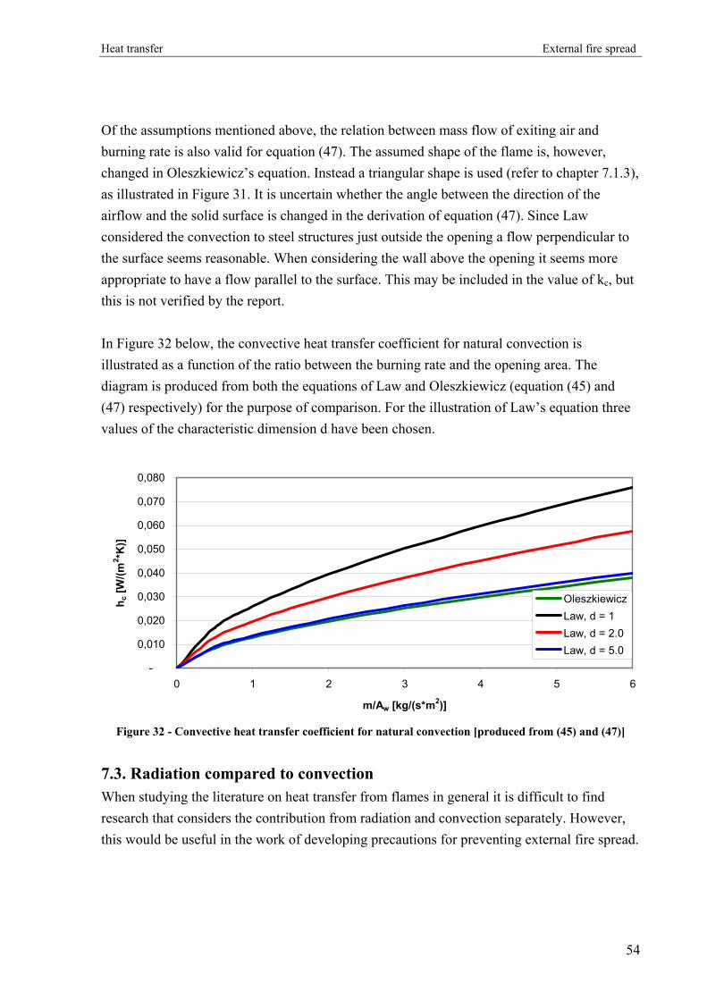
Heat transfer External fire spread
Of the assumptions mentioned above, the relation between mass flow of exiting air and burning rate is also valid for equation (47). The assumed shape of the flame is, however, changed in Oleszkiewicz’s equation. Instead a triangular shape is used (refer to chapter 7.1.3), as illustrated in Figure 31. It is uncertain whether the angle between the direction of the airflow and the solid surface is changed in the derivation of equation (47). Since Law considered the convection to steel structures just outside the opening a flow perpendicular to the surface seems reasonable. When considering the wall above the opening it seems more appropriate to have a flow parallel to the surface. This may be included in the value of kc, but this is not verified by the report. In Figure 32 below, the convective heat transfer coefficient for natural convection is illustrated as a function of the ratio between the burning rate and the opening area. The diagram is produced from both the equations of Law and Oleszkiewicz (equation (45) and (47) respectively) for the purpose of comparison. For the illustration of Law’s equation three values of the characteristic dimension d have been chosen.
-
0,010
0,020
0,030
0,040
0,050
0,060
0,070
0,080
0 1 2 3 4 5 6
m/Aw [kg/(s*m2)]
h c [W
/(m2 *K
)]
OleszkiewiczLaw, d = 1Law, d = 2.0Law, d = 5.0
Figure 32 - Convective heat transfer coefficient for natural convection [produced from (45) and (47)]
7.3. Radiation compared to convection When studying the literature on heat transfer from flames in general it is difficult to find research that considers the contribution from radiation and convection separately. However, this would be useful in the work of developing precautions for preventing external fire spread.
54

Heat transfer External fire spread
In the research on steel structures exposed to external flames Law described the calculation on both types of heat transfers. From the report it is obvious that the radiation is considered to be the most dominating mode of heat transfer. This is apparent from a statement saying that inaccuracy in determination of the conductive heat transfer coefficient only gives a small error in the total heat transfer because most of the heat is transferred by radiation. Since Law’s research only considers the heat transfer to objects just outside an opening the situation is somewhat different from the concept of vertical fire spread. It is therefore likely that Law’s assumption of a dominating radiant heat transfer cannot be used for the considerations of this thesis [38]. Oleszkiewicz described the problem of this thesis better in his research on heat transferred to the wall above the opening. In his experimental work he differentiated between the two contributions by measuring both the total heat transfer and the radiative heat transfer. The convection was then found as the difference between the two measurements. The measurements were done at 0.25 m above the opening top. Results from two of the tests are shown in Figure 33 and Figure 34.
Figure 33 - Heat transfer, 1.13 m square opening
[45] Figure 34 - Heat transfer, 0.69 m wide by 1.5 m high
opening [45]
The test results showed that for most of the measurements the radiation constituted approximately 60 % of the total heat transfer (refer to Figure 33). These tests were conducted with a square opening of 1.13 by 1.13 m. In other tests the opening was replaced by a taller and narrower one of width 0.69 m and height 1.5 m. Results from these tests showed a considerably larger contribution from convection (refer to Figure 34). The radiative contribution here was approximately the same as for the square opening [45]. These results are noticeable since they contradict Yokoi’s experiments in 1960. By the introduction of the width-to-height opening ratio, he discovered that flames emerging from narrow openings have
55

Heat transfer External fire spread
a longer projection (refer to chapter 5.2.5). It is reasonable to believe that a longer projection would reduce the temperature and flow of air passing by the opening and thereby the convective heat transfer. Oleszkiewicz does not deal with Yokoi’s work and the contradiction is therefore unexplained. Klopovic conducted the most recent research found in the literature of external flames emerging from openings. He studied the temperature and heat transfer from flames at different levels above the room of fire origin with the use of experiments. Like Oleszkiewicz, the total heat transfer was measured separately from the radiation and the determination of the convection was thereby possible. The results showed a radiative heat transfer corresponding to 30-40 % of the total heat transfer resulting in a convection of 60-70 %. Klopovic ascertained that ignition in the room above fire origin was not possible from radiation alone [33]. From the research presented above it seems reasonable to suggest that the convective heat transfer should not be neglected in the examination of secondary fires.
56

Ignition criteria External fire spread
8. Ignition criteria
8.1. Definitions In order to estimate the spread of a fire one must know the ignition criteria for materials in the vicinity of the fire. The criteria can be a certain ignition temperature or a critical heat flux to the surface. Moreover, it can be a piloted ignition or an autoignition. Most data on ignition of materials concentrate on the ignition temperature. When fire spread caused by external flames is considered, the heat flux sufficient for ignition is wanted. Heat flux criteria for piloted ignition is defined in two different ways [23]:
- Critical heat flux is the level of received heat flux below which ignition will never happen even if the material is exposed for an infinitely long time.
- Minimum heat flux is the level below which ignition will not happen if the material is exposed in a more practical range of time (usually less than 30 min.).
According to [4] this definition is also applicable for autoignition. An alternative ignition criterion is a minimum pyrolysis rate measured in g/(m2s). This criterion is easy to measure in laboratory tests, but will not be suitable for practical design use. Materials may ignite in three different manners; glowing ignition, glowing leading to flaming (2-step ignition) and direct flaming ignition. This thesis does not distinguish between these. Spearpoint et al. define three regions for the radiant ignition of cellulosic materials [56]:
- Convection controlled (very low heat flux) Ignition time is controlled by diffusion of oxygen into vaporized fuel and hot surface
- Diffusion-controlled Ignition time is controlled by thermal conduction
- Ablation-controlled (very high heat flux) Ignition time is controlled by the time to vaporize the surface fuel
Here it is assumed that a fire starts in a compartment as soon as any surface reaches its critical heat flux or its minimum heat flux for a sufficiently long time. It will not be considered whether the ignition is sustained.
57
Ignition criteria External fire spread
8.2. Materials
8.2.1. Type of materials
In a normal office or residential building the most common interiors are solids made of plastics (e.g. polyurethane for furniture stuffing) or cellulose (wood, paper, natural fabrics) in which materials of the latter are assumed dominant. In order to simplify the theory of radiant heating all materials are initially (before ignition) assumed to be homogeneous and opaque.
8.2.2. Affecting factors
Ignition times for solid materials are controlled by a several mutually dependent (and some independent) factors. These are important to keep in mind when comparing ignition data from different references. The most important factors are listed here in random order:
- The thermal inertia kρc (conductivity, density and specific heat). Vary with time as the body is heated and pyrolized and is highly dependent on the moisture content.
- Moisture content (most important for wood). The moisture acts as a thermal load and increases the thermal conductivity.
- Thermal conductivity - Emissivity. Approaching unity as the surface chars (for charring materials). - Heat flux - Exposure time - Ignition temperature - Grain orientation (for wood) - Orientation of surface (horizontal or vertical) - Thermal thickness of exposed material (relevant in the stage prior to ignition) - Charring/non-charring - Pilot location (distance from ignited item)
In the following only thickness, orientation and ignition criteria for the various materials will be discussed.
8.2.3. Thermal thickness
If a material is sufficiently thick the heat losses from the rear face will be negligible and the material will behave as a “semi-infinite” object. When the material is heated for sufficiently long time it will no longer show “thick behaviour” since the heat losses increase. When relatively thin materials are heated the loss from the rear face is significant from the initial stage and it behaves as a “thin” material.
58

Ignition criteria External fire spread
To decide whether a material would be considered thermally thick or thin, Drysdale [17]
introduce the “characteristic thermal conduction length” t⋅α , where α is the thermal
diffusivity of the material (α=k/ρ⋅c [m2/s]) and t is the exposure time in seconds. “Thermal
thickness” is assumed if the physical thickness of the material Lm > t⋅⋅ α4 . The material is
considered “thermally thin” if Lm < t⋅α . In the range between these the behaviour is neither ”thick” nor “thin”. Examples of initial thermal thickness of common materials:
Thermally thick Cellulose: - Wood furniture - Wood flooring - Window frames - Books and piles of paper
Polymers: - Polyurethane foam for furniture stuffing - Linoleum for flooring or table coating - Coatings and paint (on thick materials)
Thermally thin Cellulose: - Natural fabrics for curtains, clothing or furniture
- Sheets of paper (separated)
Protein: - Wool, mohair etc.
Polymers: - Polyester fabrics for curtains, clothing or furniture
- Cabinets for monitors, computers etc.
8.2.4. Wood
The primary constituents of wood are hemicellulose, lignin and cellulose. The first has the lowest ignition temperature while the latter has the highest. Softwoods have a smaller fraction of hemicellulose and a higher fraction of lignin than hardwoods. Therefore, softwoods have a higher ignition temperature [4]. This claim is supported by Spearpoint and Quintiere’s cone calorimeter tests on piloted ignition, which showed a slightly higher critical heat flux for Douglas fir compared to red oak [56]. Unfortunately no references define a limit between soft and hard woods. Based on their own experiences with campfires and fireplaces, most people would say that hard woods are harder to ignite than soft woods. This may be due to the difference in thickness of the wood items and members usually used for fires. Hardwood is often used for
59
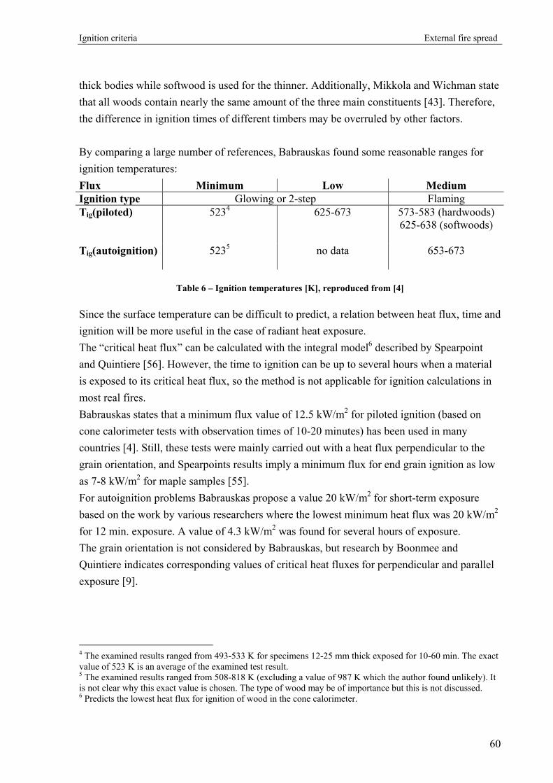
Ignition criteria External fire spread
thick bodies while softwood is used for the thinner. Additionally, Mikkola and Wichman state that all woods contain nearly the same amount of the three main constituents [43]. Therefore, the difference in ignition times of different timbers may be overruled by other factors. By comparing a large number of references, Babrauskas found some reasonable ranges for ignition temperatures: Flux Minimum Low Medium Ignition type Glowing or 2-step Flaming Tig(piloted) 5234
625-673 573-583 (hardwoods)
625-638 (softwoods)
Tig(autoignition)
5235 no data 653-673
Table 6 – Ignition temperatures [K], reproduced from [4]
Since the surface temperature can be difficult to predict, a relation between heat flux, time and ignition will be more useful in the case of radiant heat exposure. The “critical heat flux” can be calculated with the integral model6 described by Spearpoint and Quintiere [56]. However, the time to ignition can be up to several hours when a material is exposed to its critical heat flux, so the method is not applicable for ignition calculations in most real fires. Babrauskas states that a minimum flux value of 12.5 kW/m2 for piloted ignition (based on cone calorimeter tests with observation times of 10-20 minutes) has been used in many countries [4]. Still, these tests were mainly carried out with a heat flux perpendicular to the grain orientation, and Spearpoints results imply a minimum flux for end grain ignition as low as 7-8 kW/m2 for maple samples [55]. For autoignition problems Babrauskas propose a value 20 kW/m2 for short-term exposure based on the work by various researchers where the lowest minimum heat flux was 20 kW/m2 for 12 min. exposure. A value of 4.3 kW/m2 was found for several hours of exposure. The grain orientation is not considered by Babrauskas, but research by Boonmee and Quintiere indicates corresponding values of critical heat fluxes for perpendicular and parallel exposure [9].
4 The examined results ranged from 493-533 K for specimens 12-25 mm thick exposed for 10-60 min. The exact value of 523 K is an average of the examined test result. 5 The examined results ranged from 508-818 K (excluding a value of 987 K which the author found unlikely). It is not clear why this exact value is chosen. The type of wood may be of importance but this is not discussed. 6 Predicts the lowest heat flux for ignition of wood in the cone calorimeter.
60

Ignition criteria External fire spread
Ignition of wood products such as particleboard or plywood is difficult to describe generally since they are composites of wood and glue and have a non-homogeneous cross-section. Mikkola and Wichman observed a thermally thin behaviour of apparently thick particleboard samples [43]. They explain this by the difference in material density between the outer layer and the core. The core has a significantly lower density and creates an insulating layer for the thermally thin outer layer. The minimum heat flux was calculated as 11 kW/m2, which is close to the value for pure wood. Plywood (birch) also behaved thermally thin. In this case Mikkola and Wichman suggest that the glue (with relatively high density) and the outer wood layer are thermally thin and the second wood layer acts as insulation because of the density difference between glue and wood. The minimum heat flux was calculated to approximately 13 kW/m2. A factor that could affect the ignition of wood is the orientation of the exposed specimen. Janssens refer to a handful of piloted ignition test with both vertical and horizontal oriented test samples [23]. They indicate no significant difference. No direct comparison of the orientations has been found for autoignition. Babrauskas’ compiled test results from various researchers include both vertical and horizontal experiments but the test methods used are not totally comparable and the results too scattered [4]. For the properties and values described above it is assumed that the wood has no surface treatments. If the wood is treated with paint, oil or impregnation, the ignition properties are changed and will be dependent on the specific treatment.
8.2.5. Fabrics
Chen’s cone calorimeter tests with 14 different fabrics on foam stuffing [12] show that a minimum heat flux of 7 kW/m2 for piloted ignition will be reasonable for fabric/foam composites whether the burning behaviour is melting or charring, see Figure 35. The materials tested were pure fabrics of polypropylene, polyester, acrylic, cotton, viscose, nylon pile and several compositions of these.
Figure 35 – Cumulative distribution of the minimum heat flux [12]
61

Ignition criteria External fire spread
The results are supported by Babrauskas who reported the ignition of upholstered furniture by different ignition sources [6]. Figure 36 gives the relation between heat flux and time to piloted ignition for five different fabric composites. The dotted line marks a heat flux of 7 kW/m2.
Figure 36 - Ignition time results for various fabrics as a function of the heat flux [6].
Upholstered furniture is mainly assembled by fabric, that will be considered thermally thin, and some kind of foam or padding that may be considered thermally thick. Several studies indicate a thermally thin behaviour when the two materials are combined ([12], [61]). Thus, pendulous fabrics like curtains or clothes on a peg will have the same minimum heat flux as upholstered fabrics. Still, it must be considered whether the fabric will melt and drip/flow away from or towards the heat exposure. Natural fibres usually char, creating an insulating layer, while synthetic fibres mostly melt. Both Chen and Babrauskas used horizontally oriented samples in their tests. The work by Khattab indicates a significantly lower ignition time when the sample is vertically oriented but no minimum heat flux is presented [28]. When the fabric itself is a composition of several materials, it affects the ignition properties.
62

Ignition criteria External fire spread
Khattab made a series of furnace test with different compositions of cotton and polyester. They show that the time to ignition increased with increasing addition of polyester, although polyester will melt and flow at temperatures much lower than the ignition temperature of cotton [28]. When the two materials are blended and heated, the melting polyester will wick into the charred cotton, thus integrity is maintained in spite of the melting. The “coating” of polyester will slow down the pyrolized cotton products and therefore increase the time to ignition. No information has been found on the minimum radiant heat flux required for autoignition of fabrics. Khattab reports furnace temperature and (spontaneous) ignition time for various polyester/cotton composites [28] but this data is not relevant for the external flaming problem since radiation is the only potential source for autoignition. As long as the window glass is intact, the radiant heat flux will probably be critical before the room temperature has increased significantly.
8.2.6. Solid polymers
Defining a general ignition criterion for polymers will not be meaningful since they behave very different when heated. Whether the material chars, melts or form bubbles is sufficient for the order of the minimum heat flux. The Fire Protection Handbook [13] divides the polymers in three partly overlapping groups; thermosetting plastics, thermoplastics and elastomers. Thermosetting plastics are materials which are substantially infusible and insoluble after heating. Common thermosetting plastics are polyurethane (PU), polyesters, silicones, melamine and epoxy [13]. Thermoplastics cover a group of polymers that softens when heated. If desired they can be treated chemically or by heat to give a thermosetting product. Common thermoplastics are polyvinylchloride (PVC), polymethylmethacrylate (PMMA), polyethylene (PE), polycarbonate, polyesters, polystyrene (PS), polypropylene (PP), acrylics and nylon [13]. Elastomers are materials with properties like rubber. During a fire the characteristics are similar to those of natural rubber. Common elastomers are silicones, natural rubber and neoprene [13].
63

Ignition criteria External fire spread
Here, the emphasis is on the thermoplastics since they are the most commonly used polymers for objects in the building types considered, but even though the problem is reduced, there is still no general formulation of the ignition criteria. As described in the chapter on fabrics, the properties of the heated thermoplastic should be considered. If it melts when heated the position in relation to heat exposure and the combination with other materials must be determined. A melting thermoplastic could also form bubbles thus, changing the heat transfer in the material completely. For example, this is the case for PMMA [43]. If the material chars it is much easier to predict whether it will ignite or not. No reference found gives the minimum heat flux, but Hopkins and Quintiere present the critical heat flux for piloted ignition in the Cone Calorimeter of four of the most common thermoplastics: 14 kW/m2 for nylon 6-6, 9 kW/m2 for PE, 5 kW/m2 for PP and 4 kW/m2 for PMMA [21. These can be used as conservative values for piloted ignition of horizontal objects made of one of the four materials.
8.3. Summary The following tables summarize the heat fluxes described. Minimum heat flux [kW/m2] Material Piloted ignition Autoignition Wood Perpendicular to grain orientation 12.5 20
Parallel to grain orientation (7-8) (20)
7 No data Fabrics and fabric/foam composites Critical heat flux [kW/m2] Material Piloted ignition Autoignition
Nylon 14 No data Thermoplastics (examples), horizontal orientation PE 9 No data PP 5 No data PMMA 4 No data
64

Ignition criteria External fire spread
No useful references were found on radiant ignition of paper. A high fraction of the fuel load in office buildings will typically be books, folders and piles of paper. Therefore, an ignition criterion for paper is needed. For most practical design applications the minimum heat flux can be used even though materials will ignite when exposed to their critical heat flux. However, the values presented here can only be used under the conditions and assumptions described. If the scenario investigated differs from these a qualified, conservative assumption should be made on the ignition criteria. Else, references on the specific problem must be found or ignition experiments conducted. Piloted ignition values will be a reasonable conservative choice for autoignition problems if no data on this are available.
65
Precautions External fire spread
9. Precautions
Building codes from many countries have requirements for prevention of external fire spread. Therefore, the national building codes from USA, United Kingdom, Australia, Sweden and Denmark are reviewed in this chapter and the precautions are compared to available research. Additionally, alternative solutions are presented and discussed. In 2001-2002 the Building Research Establishment (BRE), UK carried out a project, which examined the phenomenon of external fire spread [14]. The objective was to provide advice on the scale of the problem and economic solutions for minimizing the risk for building users. As a part of the project building codes and regulations from a selection of countries were reviewed with respect to prevention of external fire spread through external openings. Furthermore, actual fire events and findings from these were studied. The final report concluded that external fire spread was not a significant threat to life and that the current requirements for prevention of external fire spread in United Kingdom correspond to the risk. Three different principles can be used to reduce the risk of external fire spread:
1. Prevent external flames/burning (e.g. sprinklered building)
2. Reduce or obstruct the external flame/plume (e.g. spandrels and projections)
3. Reduce or obstruct the heat exposure to openings (e.g. glazings, window sprinklers and sun screens)
Figure 37 - Three principles of reducing external fire spread
According to the American, British and Australian building codes all other precautions for the prevention of external fire spread can be ignored if sprinklers are installed throughout the building (principle 1). Room sprinklers will not be discussed further.
66

Precautions External fire spread
9.1. Spandrels One of the common precautions mentioned in the building codes, is a minimum vertical distance from the upper edge of one opening to the lower edge of the opening above, i.e. the height of the spandrel.
Figure 38 - Illustration of spandrel height
The idea of a minimum spandrel height is to have a fire resistant building construction in the hottest part of the external plume so no building material is ignited. Furthermore, the interior of rooms above the room of fire origin will not be exposed to the highest radiation (principle 2 in Figure 37). There are different opinions throughout the codes of what the sufficient height should be. In the table below, the values for the selected building codes are presented. These values are based on experience and qualified judgement, not on scientific experiments or calculations. Back in 1960 Ashton and Malhotra proved that the required spandrel dimension was insufficient and found no explanation for the chosen values [2]. The requirements have not changed significantly since then. Johnson described it this way; “The distance involved with spandrels (…) are sound technical compromises. They ensure reasonable protection at an affordable cost that achieves the required design objectives in most, but not all, fires” [24].
Country Spandrel height [mm] USA ≥ 914 (3 feet) United Kingdom ≥ 1000 Australia ≥ 900 Sweden ≥ 1200 Denmark no value specified
Table 7 – Sufficient spandrel height from selected building codes (values from [14])
67

Precautions External fire spread
The different codes all have some additional requirements to the spandrels. Generally, it is assumed that the spandrel is made of non-combustible materials or materials of a certain fire resistance. Some of the codes also suggest a certain distance of the spandrel’s extension over floor height. In the American code the spandrel requirement only applies for buildings with three storeys or more. As shown above, the Danish performance based code does not suggest a specific value for the spandrel height. It simply suggests that the risk of vertical fire spread through windows should always be evaluated. However, it does have some requirements for the materials of the exterior surfaces. It would be interesting to know how the regulatory authorities have arrived at the suggested values of spandrel height. None of the values are, however, substantiated in the codes or in the associated guidelines. Therefore, a further study was made of the Swedish Building Code and The Swedish National Board of Housing Building and Planning was contacted for information [66]. The response gave a few possible explanations with the overall assumption that a mixture between experience and experimental study is the background of the value. Reference was made to experimental research on flames emerging from windows conducted at Lund Institute of Technology in the seventies. A clear technical explanation was not available and further study of the research referred to is not possible within the scope of this thesis. In his thorough work from 1960 Yokoi developed a table-based method to calculate the necessary spandrel height (defined as the height where the plume temperature falls to 500 °C). It was based primarily on the work by other researchers and featured 8 tables from which the height could be found. Klopovic later concluded that Yokoi’s method was insufficient for the break and fall out of glass in window openings and consequently, the method underestimated the necessary spandrel height [33]. From full-scale experiments Oleszkiewicz stated that the spandrel height would be too impractical if the proper protection should be obtained. In his experiments a spandrel height of 2.5 m was needed to achieve a 50 % reduction in heat flux to the façade [46]. Consequently spandrels alone will only prevent external fire spread in very few situations. However, they reduce the risk of fire spread by a certain amount, and therefore, might serve a purpose in combination with other precautions.
68

Precautions External fire spread
9.2. External horizontal projections In some of the selected building codes horizontal projections are mentioned as an alternative to the spandrel.
Figure 39 - Illustration of projection length
The purpose of an external horizontal projection is to lead the hot gasses and flames away from the building before it moves upward due to the buoyancy (principle 2 in Figure 37). The increased distance reduces the heat exposure to the façade caused by radiation and convection. In fact, if the plume is led completely away, there is no convective heat exposure. The American code suggests the length of this kind of fire protection to be at least 762 mm (30 inches) while in the Australian code it is suggested to be 1100 mm or more. Furthermore, the Australian code requires a horizontal extension along the wall of 450 mm beyond the openings.
Country Projection length [mm] USA ≥ 762 (30 inches) United Kingdom no value specified Australia ≥ 1100 Sweden no value specified Denmark no value specified
Table 8 – Sufficient projection lenght from selected building codes (values from [14])
Generally, horizontal projections are considered difficult to implement in the building design without disturbing the architecture of the building facades. The method has, however, showed to be very effective and therefore cannot be neglected. A method to implement the projections in office and residential buildings is to include the protecting slab in the construction of a balcony or as a canopy. As for spandrel heights the values of necessary horizontal projection length are not substantiated in the building codes.
69

Precautions External fire spread
In his small-scale (and one full-scale) experiments Yokoi also studied the effect of horizontal projections on the external plume [64]. Both a single projection and the effect of two projections were tested as illustrated in Figure 40.
Figure 40 - Positions of two projections in Yokoi’s small-scale experiments [64].
He observed that even though the plume is projected away from the façade, it would converge to the trajectory of the situation with no projection. The higher the plume rises from the projection, the more it has the shape of the “no-projection” plume. Figure 41 shows the trajectories from small-scale experiments with three different opening dimensions and six projection depths.
Figure 41 - Trajectories of upward plumes from different opening dimensions. The figure to the right is data from experiments with two projections [64].
70

Precautions External fire spread
The right figure illustrates the trajectories from experiments with two projections. It is clear that the effect of the second projection is almost insignificant. Oleszkiewicz examined the effect of horizontal projections in a full-scale model with three projection depths and two different heat release rates [46]. The projections were inserted and moved instantaneously with a pivot joint when the heat release rate had stabilised. Figure 42 is an example of the experiments where the heat flux density (radiation + convection) to the façade was measured at 1, 2 and 3 meters above the opening.
Figure 42 - Heat flux measurements at 1, 2 and 3 m above the opening for a 1 m deep projection [46].
A significant reduction in the heat flux is seen in the periods where a projection is deployed. As soon as the projection is removed the heat flux returns to the same level as before. When a projection is deployed the relative heat flux difference along the wall is smaller. This is more clearly illustrated in Figure 43 where four different projection depths (0, 0.3, 0.6 and 1 m) are compared. The slopes of the lines decrease with increasing projection depth, and with the 1 m projection there is no significant difference in heat flux from 0.5 m to 3.5 m above the opening.
71

Precautions External fire spread
Figure 43 - Relative heat flux data for various projection depths, normalized by data at 1 m above the
opening with no projection [46].
The author concludes that a 0.6 m projection reduces the heat flux to the façade by approximately 60 % compared to experiments without projections and with the 1 m projection reduces it by 85 % at 1 m above the opening. The same experiments indicate that the 0.3 m projection achieves the same level of protection, 1 m above the opening, as a 2.5 m spandrel wall. With a 0.6 m projection this level is achieved at less than 0.5 m above the opening. Galea et al. confirm that a 1 m projection is sufficient to protect high-rise buildings from external fire spread [20]. In a two-dimensional numerical study Satoh et al. examined the effect of façade geometry on the external plume [51]. Different projection depths were examined in a model with four storeys above the room of fire origin. Flow patterns illustrated by isotherms show that a part of the external plume is “caught” in the cavities between the projections and an eddy is created outside every storey. These eddies will probably transmit heat from the upward plume to the façade since they continuously entrain hot gasses. The 1/7-scale fire experiments by Suzuki et al. concentrated on the variations in external plume properties with different projection depths [58]. Five depths (0, 10, 15, 20 and 25 cm) were tested and the temperatures were measured with thermocouples in a grid perpendicular to the façade. Figure 44 shows the isothermal line drawn from the temperature data.
72

Precautions External fire spread
Figure 44 - Isothermal lines in cross section in the middle of the opening. Dashed lines are trajectories
[58].
It is clear that a deeper projection results in a longer distance from façade to trajectory. Even though some of the hot gasses get close to the façade in all cases, they are much cooler in the deep projection cases. Therefore, the “local eddies” indicated in Satoh’s work may not be a great risk. The 10 cm projection results deviated from the rest of the experiments. The length and angle of the ejected plume was larger than the plume in the reference experiment where no projection was present. No explanation of this phenomenon is given in the reference. An interesting observation that is only described in the work by Suzuki et al. is that the temperature in the room of fire origin increases with increasing projection depth. This is explained by the fact that the fresh air flowing into the room through the lower part of the opening passes the hot gasses flowing out over a longer distance. Thereby the inflowing air is preheated. Mammoser further developed the work by Suzuki et al. He used a three-dimensional numerical model to investigate the same 1/7-scale model and added balustrades and vertical separation walls in some of the experiments [42]. He found that a projection with solid balustrades trapped the hot gasses on each storey, especially when solid separation walls were applied. A projection with an open balustrade and no separation walls was found to give the best protection from the external plume. No reference found has given a method to estimate the properties of the external plume when different projection and balustrade geometries are applied. Therefore, conservative assumptions on the effects must be made from the behaviour described above. If the evaluated
73
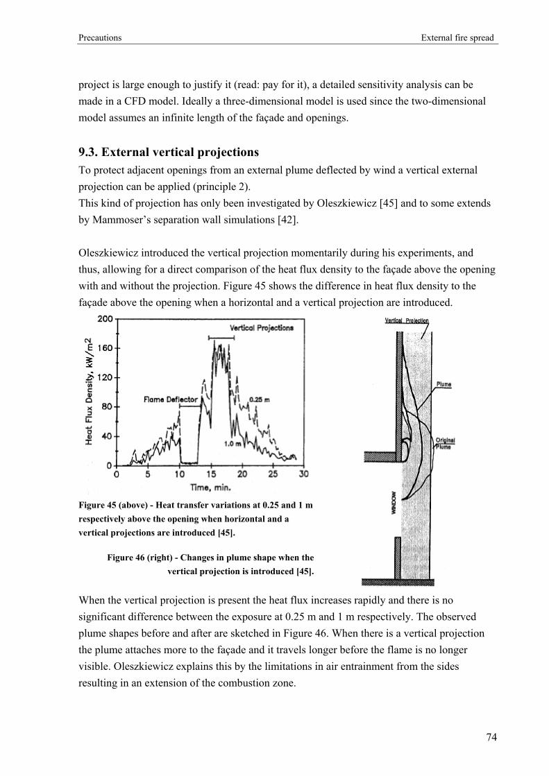
Precautions External fire spread
project is large enough to justify it (read: pay for it), a detailed sensitivity analysis can be made in a CFD model. Ideally a three-dimensional model is used since the two-dimensional model assumes an infinite length of the façade and openings.
9.3. External vertical projections To protect adjacent openings from an external plume deflected by wind a vertical external projection can be applied (principle 2). This kind of projection has only been investigated by Oleszkiewicz [45] and to some extends by Mammoser’s separation wall simulations [42]. Oleszkiewicz introduced the vertical projection momentarily during his experiments, and thus, allowing for a direct comparison of the heat flux density to the façade above the opening with and without the projection. Figure 45 shows the difference in heat flux density to the façade above the opening when a horizontal and a vertical projection are introduced.
Figure 45 (above) - Heat transfer variations at 0.25 and 1 m respectively above the opening when horizontal and a vertical projections are introduced [45].
Figure 46 (right) - Changes in plume shape when the vertical projection is introduced [45].
When the vertical projection is present the heat flux increases rapidly and there is no significant difference between the exposure at 0.25 m and 1 m respectively. The observed plume shapes before and after are sketched in Figure 46. When there is a vertical projection the plume attaches more to the façade and it travels longer before the flame is no longer visible. Oleszkiewicz explains this by the limitations in air entrainment from the sides resulting in an extension of the combustion zone.
74

Precautions External fire spread
Mammoser observed similar tendencies with separation walls but explained it by the “chimney effect”. Since vertical external projections increase the heat exposure to the façade above the room of fire origin they should only be used in combination with horizontal projections or other appropriate precautions.
75

Precautions External fire spread
9.4. Glazing
9.4.1. General
In a fire situation, one of the weakest links in a building is its window glass. Due to the thermal stresses, normal glass will crack and may fall out when exposed to relatively low temperatures resulting in an increased supply of oxygen to the room of fire origin. Thus, this thesis assumes that the window glass in the room of fire origin will always crack and fall out. When considering the room above fire origin, a window missing the glass gives a sufficiently higher risk of ignition. If integrity is maintained, the glass reduces the risk of fire spread in three ways (all using principle 3):
• Radiative heat transfer is reduced [5]7. • Convective heat transfer to the interior is excluded. However, the window will be
heated by convection leading to internal radiation from the glass and frames. • Sparks are prevented from entering the room. When there are no pilots, the minimum
heat flux required for ignition is higher. Mowrer has made a thorough research on the breakage of window glass exposed to exterior fires (defined as a uniform, radiant heat flux) [44]. He made sixty-one small-scale experiments and nineteen experiments with commercially available windows exposed to radiant heat fluxes of 2-18 kW/m2. The main conclusion on normal window glass is that a single layer window with no protective treatments will fail when exposed to a heat flux in the range of 4 to 5 kW/m2. The window glass is said to fail when it cracks. Whether it falls out is not a fail criterion in the experiment but there is a certain probability for this when the glass has cracked. The probability of the glass falling out is fairly unpredictable so a conservative assumption will be that cracking immediately leads to fall out of normal glass without protective treatments. Many windows in modern buildings have more than one pane. When a double-pane window is exposed to a radiant heat flux, only the first pane will absorb the amount of energy sufficient for cracking. Due to the spectral radiant absorption characteristics, most of the energy that is transmitted through the first pane also transmits through the second. This way
7 Babrauskas reported a 2/3 reduction when passing through a layer of single-strength pane of ordinary glass. The Swedish Brandskyddshandboken specify a reduction of 30-50% for wired, uninsulated glass [Brandskyddshandboken].
76
Precautions External fire spread
the first pane protects the next panes and therefore, multi-pane windows can be expected to maintain integrity much longer during a fire. The window frame also plays a part in the performance of the window. In terms of the thermal stresses the heat-up phase is critical. During this period a high temperature difference is built up between the middle of the pane and the edge, which is shielded by the window frame. Mowrer’s research shows that a vinyl frame tends to fail before the glass falls out, resulting in a collapse of the entire window. Babrauskas refers to other research indicating that glass in an aluminium frame lasts longer than glass in a wood frame [5]. This may be a result of the difference in heat conductivity or thermal expansion between aluminium and wood. Sophisticated models to predict the time to window breakage have been developed by Joshi and Pagni [25] among others. These models are mostly relevant for controlled conditions in laboratories and will not be discussed here.
9.4.2. Fire-resistant glazing
A well-known method of making a fire resistant glass is by applying a mesh of metal wires embedded inside the glass. The mesh assures a certain integrity in the glass even when it is fully cracked and thereby maintains a barrier for smoke, sparks and flames. Moreover, it provides a certain level of safety for people on both sides of the glass since no fragments will fall out if the glass is broken by accident. However, wires are very visible and thereby affect the architecture. Therefore, wired glass is mainly used in fire rated doors or where the glass is less visible. Several types of fire resistant glass without wires have been developed. These are made with raw materials and/or fabrication methods different from traditional glass. The fire resistant glass can be tempered glass, heat-strengthened glass, ceramic glass and sandwich structure glass containing layers of polymeric materials. A great advantage of some of these types of glass is that their fire resistance is invisible. Thus, replacing normal windows with them will not affect the architecture. The fire resistance (and other properties) of the various types of glass are different and an individual judgement must be made when they are used in fire protection design. The fire resistant glazing can be classified in two categories providing either “integrity” or “integrity and insulation” [30]. Both will be suitable for protection against external fire spread.
77

Precautions External fire spread
International standards describe how glass can be classified or rated. For example the ASTM8 has a test method where the glass can achieve a 45-minute rating, a 60-minute rating or a three-hour rating [49]. The test temperatures increase with increasing time rating following a standard temperature/time-curve as indicated in Figure 47. After heat exposure the glass is sprayed with water while it is still hot. This imitates the spray from a sprinkler or a fire-fighters hose. Some test methods involve the impact of a steel ball after heat exposure.
273
473
673
873
1073
1273
0 50 100 150 200
Time [min]
Tem
pera
ture
[K]
Figure 47 - Example of temperature/time curve and 45-, 60- and 180-minute glass ratings (marked with
dotted lines).
To give an impression of the fire resistance, examples are given: According to Underwriters Laboratories Inc.9 wire glass has a 45-minute fire rating for areas up to 0.836 m2 with no dimension over 1.35 m. Areas up to 0.645 m2 has a 90-minute rating [49]. Mowrer tested ceramic glass and tempered glass in his small-scale experiments. Neither failed when exposed to heat fluxes of approximately 16 kW/m2 for periods of up to 15 minutes. During this exposure the wood frame started charring and the glazing putty puffed up [44]. Ceramic glass can carry fire ratings of up to three hours (test method unknown) [49]. Babrauskas refer to an experiment with heat-strengthened and tempered glass where a radiant heat flux of 43 kW/m2 did not cause cracks [5]. 8 ASTM: American Society for Testing and Materials 9 Underwriters Laboratories Inc.: An independent, non-profit testing and certification organization.
78

Precautions External fire spread
Considered as passive fire protection, fire resistant glass is fairly good since it has functionality in the no-fire situation by providing light to the building. For obvious reasons they will quickly be replaced if broken accidentally during daily use. However, they will still be useless if left open on the day of a fire incident.
9.4.3. Foil laminates
Some buildings with large glass facades have windows with foil-laminated glass. The laminate can be fully transparent or have a certain tinting which reduces the sun radiation, changes the architectural appearance and partly hides the content of the building from curious eyes. The laminate is expected to provide an increased period of integrity in the case of fire. When the glass is cracked, the foil keeps the pieces of glass in their initial position for some time. Additionally, the laminate deflects some of the radiant heat flux. Mowrer used aluminium foil and vinyl shade film in his small-scale experiments [44]. When aluminium foil was applied to the exposed side of the glass, less than 2 % of the heat flux was transmitted through the window. The glass remained relatively cold and did not crack. On the other hand, when the foil was attached to the unexposed side, the glass cracked at a heat flux of approximately 70 % of the failure-value for non-laminated glass. The unanswered question is whether the foil should be applied on the inside or outside. Inside foil is best in the room of fire origin and outside foil is preferable in the room exposed to external flames. It is not clear how transparent the foil used by Mowrer was. If too opaque, it is not really suitable for laminating an entire building façade. The vinyl shade film in the experiments didn’t increase the time to cracking of the glass, but an increased time of integrity may be expected.
9.4.4. Insect screens
To prevent insects from penetrating buildings the openings can be covered by a thin, transparent mesh. If the mesh and mounting are made of a fire-resistant material it will provide a certain protection from external flames. It reduces the radiant and convective heat flux to the opening or window glass and prevents sparks and burning items from entering the building. Mowrer tested both aluminium and black fibreglass meshes attached to the exposed side of the window [44]. The mesh did not prevent the glass from breaking but the heat flux at breakage was increased by 21 % for single strength glass. The reduction of penetrating heat flux will be highly dependent on the specific mesh product. An Australian manufacturer of a
79

Precautions External fire spread
metal wire insect screen mesh that is also used for protection against burglary claims that their product “will reduce the intensity of radiant heat flux and naked flame by up to 45 %” [67]. Even though a statement like this should be closely evaluated when it comes from the manufacturer it still indicates a scatter in the protective effects of insect screens.
9.4.5. Window sprinklers
An alternative way of protecting glazing exposed to external flames is a sprinkler system pointed directly on either the inside or outside of the pane as illustrated in Figure 48. A constant stream of water on the entire surface will prevent the glass from reaching critical temperatures and thereby maintain integrity (principle 3). Additionally, the water absorbs some of the radiative heat flux that would have transmitted through the glass. Window sprinkler will only be useful if the windows cannot be opened since the level of protection is highly dependent on the flow pattern down the pane.
Figure 48 - Window sprinkler
Kim et al. have tested the performance of both inside and outside sprinklers in combination with plain glass and tempered glass [29]. They concluded that the water spray to the glass should start within 1 min. Otherwise the effect may be negative since the glass temperature has increased to a high level and the water will induce a thermal shock. Plain glass cannot be protected by either the interior or the exterior system. As a minimum tempered glass must be used. Interior systems Interior mounted sprinklers have the advantage of being protected from weather. Thereby less maintenance is required and no anti-freeze system is needed. Interior sprinklers may also protect glazing in the room of fire origin and prevent external flames from occurring initially. This way they will be part of the normal ceiling-mounted building sprinkler system. Kim et al. concluded:
80
Precautions External fire spread
• If quick response sprinklers are used the glass can be protected from both large compartment fires and small fires located adjacent to the glazing.
• An exterior detection system is recommended in order to give a fast water delivery. • More than one sprinkler should be used if the pane has a width of 3.6 m or more. The
distance between sprinklers must be at lest 2 m to prevent negative interaction. • The ideal location of a ceiling mounted quick response sprinkler is 300 mm above the
window and 300 mm from the window with a minimum sill depth. Exterior systems Exterior mounted sprinklers are exposed to the impact of wind, high temperature variations including frost and direct sunlight, pollution, insects, birds etc. This requires a robust, frost-resistant system and more maintenance. However, exterior sprinklers will both protect the glass and cool down the external plume thus giving protection for storeys above. Furthermore, activation (unintended or in a fire situation) will not have the same expensive consequences as interior sprinklers since the water is kept outside. Kim et al. concluded:
• Sprinklers mounted on the exposed side of the glass give effective protection from radiant heat exposure. They may also protect the glass from a fire in an adjacent building.
9.5. Sun screens
9.5.1. Louvres
A widely used type of sunscreen in buildings with large glass facades is exterior mounted louvres. They provide a certain shielding against the sun, but also have a major impact on the appearance of the building. They can be either vertically or horizontally oriented, but only the latter will be discussed here. Often, the louvres are adjustable manually or by an automatic mechanism controlled by the amount of sunlight exposure to the building. If the louvres are in their normal position during a fire situation, as illustrated in Figure 49A, a kind of “chimney effect” would be expected in the gap between the façade and the louvres. If some of the hot gasses escape to the outside of the “chimney” they will be entrained back into the main plume through the space between the louvres, as they are moving upwards.
81
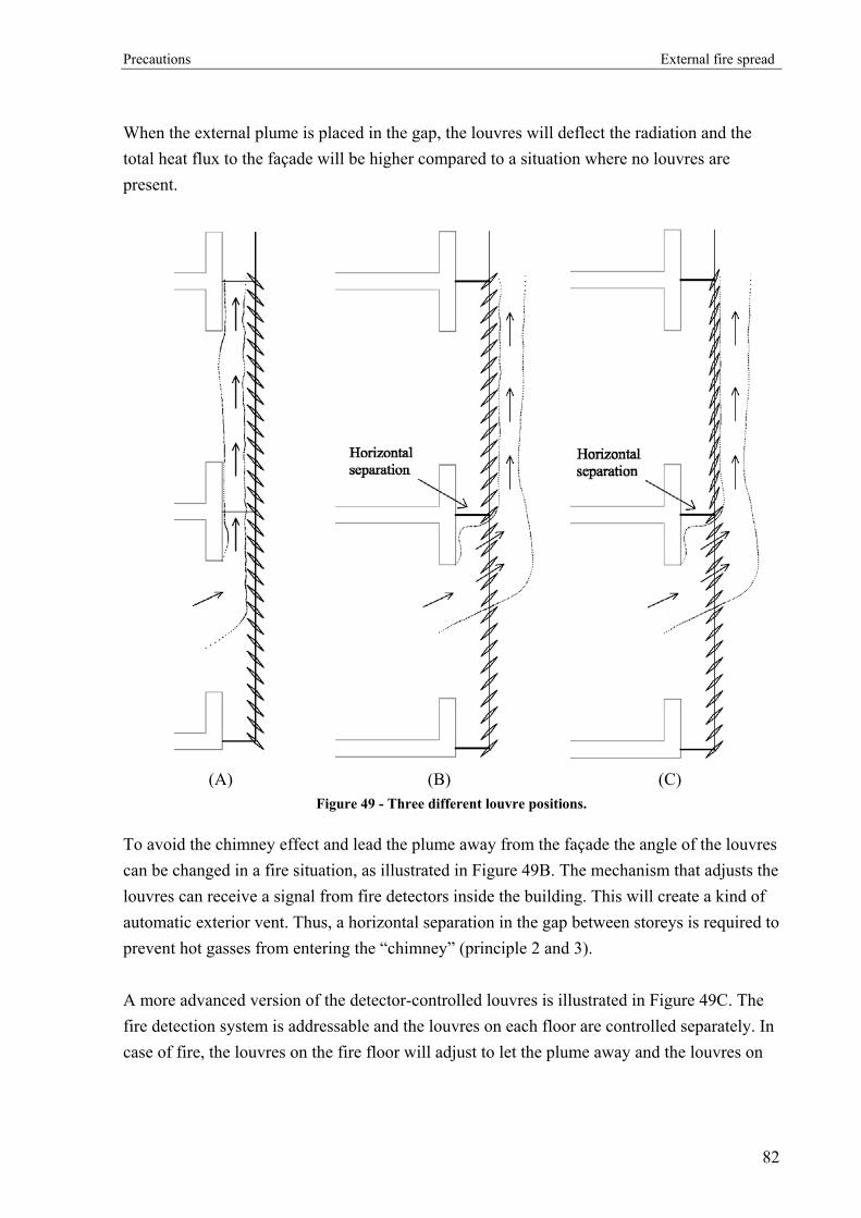
Precautions External fire spread
When the external plume is placed in the gap, the louvres will deflect the radiation and the total heat flux to the façade will be higher compared to a situation where no louvres are present.
(A) (B) (C)
Figure 49 - Three different louvre positions.
To avoid the chimney effect and lead the plume away from the façade the angle of the louvres can be changed in a fire situation, as illustrated in Figure 49B. The mechanism that adjusts the louvres can receive a signal from fire detectors inside the building. This will create a kind of automatic exterior vent. Thus, a horizontal separation in the gap between storeys is required to prevent hot gasses from entering the “chimney” (principle 2 and 3). A more advanced version of the detector-controlled louvres is illustrated in Figure 49C. The fire detection system is addressable and the louvres on each floor are controlled separately. In case of fire, the louvres on the fire floor will adjust to let the plume away and the louvres on
82
Precautions External fire spread
all other floors (above the room of fire origin) switch to a vertical position. This way neither radiation nor hot gasses can reach the other floors (principle 2 and 3). This kind of active fire protection could be easily applied since most modern buildings already have a fire detection system and a louvre adjusting mechanism. Thus, it is very important that the entire system is fire-resistant. The lamellas, for example, are often made of aluminium that has a very low melting temperature but also wires and anchoring needs to be considered. A changed louvre position could also make it more difficult for the fire brigade to reach the façade and openings with the water jet.
9.5.2. Blinds
Another precaution could be blinds, which are widely used to shield windows in office buildings from sunlight. If unrolled in a fire situation, they can protect openings around the room of fire origin from both radiant and convective heat as long as integrity is maintained (principle 3). Blinds are typically made of some kind of fabric and are activated by either a manual or an automatic mechanism controlled by time or sunlight. Similar to the louvres they are tested during everyday use since they have a purpose in the no-fire situation. If used as an active fire protection system blinds should be activated by fire detectors. Similar to the louvre system an addressable system is recommended so that blinds in the room of fire origin are wound up (or not activated). An important difference between louvres and blinds is that the blinds are more integrated in the façade so the “chimney effect” is not a problem. Whether the blinds are made of natural or synthetic materials, they should be fire-resistant to some degree to avoid flame spread on the surface and to maintain integrity in the blinds. A problem is that some fire-resistance treatments break down when exposed to UV-light., Attention should be directed to this problem, especially when they are used as an active fire protection against external fire spread A simple solution is to mount the blinds on the interior side of the windows. The UV-light is stopped by glass and at the same time both blinds and activation mechanism are protected from rain and daily temperature differences, thus increasing longevity of the system. Interior mounting will probably reduce time before cracking of the window glass in a fire situation, but this is less critical if the blind maintains integrity.
83

Precautions External fire spread
9.6. Discussion In 1960 researchers from the United Kingdom questioned dimensions of fire precautions presented in the building codes. In Byelaws from 1952 a spandrel height not less than 3 feet (914 mm) is suggested and as an alternative solution horizontal projections of 2 feet (610 mm) or more. The researchers found no explanations to the values and doubted the efficiency of these measures. When studying the selected building codes of today it seems remarkable that none of the values are substantiated directly or have clear references to research supporting the suggested precautions. Furthermore, it seems strange that the values used for guidelines in the UK have not changed considerably since 1952 and are still to be found in the current building code. The conclusion of the BRE project indicates that this regulatory authority does not consider external fire spread via external openings a major problem. It is important to note that the result of the BRE report is based primarily on the statistics of casualties from major fires. Even though human life safety is traditionally the main object for fire safety engineering a judgment of property damage and business interruption would be valuable in a risk assessment of external fire spread. Since the report does not describe the theory and research of the phenomenon the conclusion of the entire project does not cover all aspects of the problem. Yet, they make a good point saying that the internal compartmentation of modern buildings has reached such a high level that the relative risk to life from external fire spread is getting higher. Furthermore, they do not consider the possibility of untraditional building geometries due to the use of performance-based codes. E.g. the stairwells don’t have to be continual vertical shafts along the entire length of the building. This way, a room fire could expose the escape routes to external flames. Generally, new designs could put the escape routes at risk if external fire spread is not considered. Therefore, also life safety should be considered when the risk of external fire spread is evaluated. From the considerations above it does not seem reasonable to use values from the building codes as the only guidelines for protection against external fire spread. Instead, alternative solutions, which have been tested and researched, may be considered in combination with the requirements. When alternative solutions are considered it will be useful to acknowledge what stage of the fire development it affects. The three reduction principles described above can be used for classification. The best solutions use principle 1, since they reduce the fire origin. Then, problems like fire spread inside the building or to adjacent buildings are reduced.
84

Conclusion External fire spread
10. Conclusion
The phenomenon of fire spreading from one room to another via external openings has been evaluated through a comprehensive study of literature where results and findings from previous research have been compared and discussed. The objective has been to evaluate the various problems involved and if possible prepare some guidelines for estimation of the risk of fire spread.
10.1. Findings A little less than thirty references concerning fires outside external openings were found. Since several references cover the same research program and some of them are more than forty-five years old this seems like very few. From the beginning of the nineties about half the research programs on external fire spread have used numerical simulation for evaluation of the problems. Numerical models are useful supplemental tools but real small- or full-scale experiments will still be needed for verification. At the beginning of this thesis it became clear that the best way to describe the issues of this problem was by a chronological review of the various properties and circumstances leading to external fire spread. First of all, the conditions in the room of fire origin must be considered. Especially the size of the external opening has proven to be crucial, since it controls the transition between fuel and ventilation controlled regime. This also means that the vent is decisive for the amount of energy released from the fire, and thereby whether flames will emerge from the opening or not. Whether the flames emerge as combustion of fuel rich gasses from a gas layer or extensions of flames from the fire origin, is determined by a combination of the opening area, the room geometry and amount of energy released. Empirical methods for estimation of external flame dimensions were developed in the seventies with the purpose of predicting fire safety of bare external steel elements. Unfortunately they were based on a flame tip defined as the point where the flame temperature falls to 813 K. This may be a “safe” temperature limit for steel but in terms of radiant and convective ignition there is no clear “safe” limit. Therefore, the methods must be used with care. A very important issue, which is still almost unexplored, is the behaviour of the external plume when it passes the opening to a room above the room of fire origin. A single CFD-
85

Conclusion External fire spread
research project indicates that a part of the plume will enter the room, thus exposing its interior to a heat flux that is quite different from the scenario where the entire plume passes outside the opening. The transfer of heat from the flames to the room above fire origin is essential for the spread of fire. In the work of determining the heat transfer two variables are interesting and have been investigated exhaustively through time. The emissivity ε that controls the amount of radiation and the convective heat transfer coefficient hc that decides how much heat is transferred by convection. Early research indicated that the convective fraction of the total heat transfer is insignificant but later investigations have shown that convection is not negligible. The last step in fire spread between external openings is the ignition of a combustible material in a room above or adjacent to the room of fire origin. Even though the ignition of materials has been studied thoroughly for many years it is still difficult to predict. The number of variables and uncertainties are simply too high. Precise predictions can only be carried out when the scenario is very well defined and static but this is very uncommon in a real life building. Minimum heat fluxes for ignition of a selection of widely used materials are, however, presented in this thesis to give some kind of guideline and show the magnitude of critical levels. The presence and integrity of window glass was found to be very important to the risk of ignition. It affects both the amount of radiant and convective heat transfer and the possibility of pilots and hot gasses entering the room. A potential approach to evaluate the problem of fire spread between external openings is summarized in the following flow chart:
86
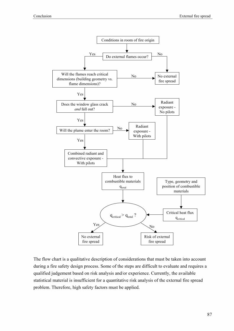
Conclusion External fire spread
Do external flames occur?
No external fire spread
No
Will the flames reach critical dimensions (building geometry vs.
flame dimensions)?
Yes
No
Yes
Does the window glass crack and fall out?
Yes
Will the plume enter the room?
Yes
Combined radiant and convective exposure -
With pilots
Radiant exposure -No pilots
No
Radiant exposure -With pilots
No
Heat flux to combustible materials
qtotal
Type, geometry and position of combustible
materials
Critical heat flux qcritical
qcritical > qtotal ?
No external fire spread
Risk of external fire spread
NoYes
Conditions in room of fire origin
The flow chart is a qualitative description of considerations that must be taken into account during a fire safety design process. Some of the steps are difficult to evaluate and requires a qualified judgement based on risk analysis and/or experience. Currently, the available statistical material is insufficient for a quantitative risk analysis of the external fire spread problem. Therefore, high safety factors must be applied.
87

Conclusion External fire spread
If the fire safety designer determines a significant risk of external fire spread, precautions must be taken. Three different principles can be used:
• Prevent external flames/burning • Reduce or obstruct the external flame/plume • Reduce or obstruct the heat exposure to other openings
Most building codes concentrate on the first two principles. If a building is not sprinklered a vertical separation (spandrel wall) or a horizontal projection between openings is often required. The required vertical separations were found to be insufficient for prevention of fire spread between openings. Horizontal projections are much more effective but from an architectural point of view, they are often undesirable. When the building codes are fulfilled supplemental precautions can be considered. Alternatives described in this thesis are: fire-resistant glass, window sprinklers, louvres and blinds.
10.2. Research to be done in the future The study of the BRE report has shown that the risk of external fire spread is not considered to be substantial by the regulatory authorities in United Kingdom. However, the material damages and the extent of business interruption can be substantial, which may increase the attention from insurance companies and building users. This could be further investigated through a cost-benefit analysis if the necessary statistical data is available. A number of full- or small-scale experiments in a multi-storey building combined with CFD-simulations would be useful in order to further investigate the following:
• The distribution of radiant and convective heat transfers to room openings exposed to external flames.
• The trajectory of an external plume when it passes an opening. • Support the findings of previous research, especially Klopovic whose result in some
points differs from earlier research. • Qualitative expressions for the effect of various precautions. • Provide statistical material for risk analysis.
Additionally, more data is needed on the ignition of various materials by radiation and convection. Especially, criteria for autoignition of fabrics are wanted since radiant exposure to curtains through window glass is a common scenario.
88

Nomenclature External fire spread
11. Nomenclature
Af Surface area of fuel [m2] At Total enclosure surface area [m2] AT Area of enclosing surfaces minus opening area (AT = At – Ao) [m2] Ao Area of opening [m2] b Plume radius [m] B Dimensionless parameter [-] c Specific heat of gasses or material [kJ/kg⋅K] ca Specific heat of ambient air [kJ/kg⋅K] C Effective heat of combustion [kJ/kg] d Characteristic dimension [m] D Equivalent opening diameter = 2r0 [m] F Configuration factor [-] g Acceleration due to gravity [m/s2] hc Convective heat transfer coefficient [W/(m2⋅K)] Hf Height from fuel to ceiling [m] Ho Opening height [m] H” Distance from neutral zone to upper edge of opening [m] lf Flame height [m] I Intensity of radiation [W/m2] k Thermal conductivity [W/(m⋅K)] l Distance along flame centre line from opening (l = X at flame tip) [m] L Flame thickness [m] Lm Material thickness [m]
•
m Burning rate [m]
airm•
Air flow rate [kg/s]
fm•
Fuel mass loss rate [kg/s]
n Width-to-height opening ratio = 2wo/Ho [-] Nu Nusselt number [-]
•′′q Heat flux [kW/m2]
•′′rq Radiative heat flux [kW/m2]
•′′cq Convective heat flux [kW/m2]
89

Nomenclature External fire spread
•
Q Energy release rate or heat release rate [kW]
oQ•
Heat release from external opening in room of fire origin [kW]
r Stoichiometric fuel/air ratio for complete combustion [-] rc Radial distance from plume radius [m]
r0 Equivalent window radius π⋅⋅
=2
hw [m]
Re Reynolds number [-] T Absolute temperature of an object [K] T0 Flame temperature at opening (l = 0) [K] Ta Ambient temperature [K] Tf Temperature of fluid [K] Tmax Maximum temperature of ceiling jet [K] Tp Temperature on the plume centreline [K] Ts Temperature of solid [K] u Velocity of gasses [m/s] up Plume velocity [m/s] uw Wind velocity [m/s] umax Maximum velocity of ceiling jet [m/s] wo Opening width [m] W1 Width of compartment [m] W2 Depth of compartment [m] x Distance from wall to the middle of the flame [m] X Flame length along flame axis [m] yi Yield of species i [-] z Height of flame tip above opening [m] α Thermal diffusivity [m2/s] ∆Hc Heat of combustion [kJ/kg] ∆T Excess temperature of ceiling jet (∆T = Tmax – Ta) [K] ∆Tp Excess temperature on the plume centreline (∆Tp = Tp – Ta) [K] ∆Tz Effective mean temperature rise at l (∆Tz = ∆Tl for l = X) [K] ∆Tl Effective mean temperature rise at the flame tip [K] Θ Dimensionless temperature [-] φ Equivalence ratio [-] ε Emissivity [-]
90

Nomenclature External fire spread
εflame Emissivity of flame [-] κ Absorption coefficient [m-1] µ Viscosity of gasses [N⋅s/m2] ρ Density of gasses [kg/m3] σ Stefan-Boltzmann constant ( = 5.67⋅10-8) [W/(m2K4)] AT Area of enclosing surfaces minus AW [m2] Aw Area of windows from which flames emerge [m2] c Specific heat of gasses [kJ/kg] C Effective heat of combustion [kJ/kg] D Equivalent window diameter = 2r0 [m] g Gravity [m/s2] h Window height [m] lf Flame height [m] l Distance along flame centre line from window (l = X at flame tip) [m] n Width-to-height window ratio = 2w/h [-] Q Heat release from window in room of fire origin [kW]
r0 Equivalent window radius π⋅⋅
=2
hw [m]
Burning rate [kg/s] T0 Flame temperature at window (l = 0) [K] Ta Ambient temperature [K] u Wind velocity [m/s] w Window width [m] W Width of compartment [m] X Flame length along flame axis [m] z Height of flame tip above window [m] ∆Tz Effective mean temperature rise at l (∆Tz = ∆Tl for l = X) [K]
∆Tl Effective mean temperature rise at the flame tip [K]
ρ Density of gasses [kg/m3]
R
91

References External fire spread
12. References [1] Alpert, R. L., Calculation of response time of ceiling-mounted sprinklers, Fire
Technology, Vol. 8, pp. 181-195, 1972.
[2] Ashton, L. A. and Malhotra, H. L., External walls of buildings – Part I: The protection of openings against spread of fire from storey to storey, Fire Research Note No. 436, Department of Scientific and Industrial Research and Fire Offices’ Committee, Joint Fire Research Organization, Fire Research Station, Borehamwood, 1960.
[3] Babrauskas, V., Temperatures in flames and fires, Fire Science and Technology Inc., 1997.
[4] Babrauskas, V., Ignition of wood: A review of the state of the art, Fire Science and Technology Inc., 2002.
[5] Babrauskas, V., Glass breakage in fires, Fire Science and Technology Inc., 2003.
[6] Babrauskas, V. and Krasny, J., Fire behavior of upholstered furniture, NBS Monograph 173, National Bureau of Standards, U.S. Department of Commerce, 1985.
[7] Bechtold, R., Ehlert, K.-P. and Wesche, J., Brandversuch Lehrte, Schriftenreihe “Bau- und Wohnforschung” des Bundesministers für Raumordnung, Bauwesen und Städtebau, Report nr. 04.037, 1978.
[8] Bechtold, R., The role that facades play in fire spread - 2, Fire International: The Journal of the International Fire Protection Services, Vol. 5, Issue 59, 1978.
[9] Boonmee, N. and Quintiere, J. G., Glowing and flaming autoignition of wood, Proceedings of the Combustion Institute, Vol. 29, pp. 298-296, 2002.
[10] Bullen , M. L. and Thomas, P.H., Compartment fires with non-cellulosic fuels, 17th Symposium (International) on Combustion pp. 1139-1148, The Combustion Institute, Pittsburgh, 1978.
[11] Carlsson, E., External fire spread to adjoining buildings, Department of Fire Safety Engineering, Lund University, Sweden, 1999.
[12] Chen, F. F., Radiant ignition of New Zealand upholstered furniture composites, The University of Canterbury, The Department of Civil Engineering, 2001.
[13] Cote, A. E. (editor), Fire Protection Handbook – 17th edition, National Fire Protection Association, 1991.
[14] Crooke, C., External fire spread via windows - closing report, Building Research Establishment, Fire and Risk Sciences Division, report nr. 203141, 2002.
92

References External fire spread
[15] Danish Standards Association, Code of practice for the structural use of steel – DS 412, Danish Standards Association, 1998.
[16] DiNenno, P.J., SFPE Handbook of Fire Protection Engineering – 3rd edition, NFPA, 2002.
[17] Drysdale, D., An Introduction to Fire Dynamics – 2nd edition, John Wiley & Sons, 1998.
[18] Fleischmann, C. M., Radiant ignition of adjacent upholstered furniture - A simple approach, NIST SP 998, 2003.
[19] Galea, E. R., Berhane, D. and Hoffmann, N., CFD analysis of fire plumes emerging from windows in high-rise buildings, Proc International Conference, Fire safety by Design, Vol. 3, pp. 111-120, 1995.
[20] Galea, E. R., Berhane, D. and Hoffmann, N., CFD analysis of fire plumes emerging from windows with external protrusions in high-rise buildings, Proceedings of the 7th INTERFLAM conference, 1996.
[21] Hopkins, D. and Quintiere, J. G., Material fire properties and predictions for thermoplastics, Fire Safety Journal 26, pp. 241-268, Elsevier Science, 1996.
[22] Fristrom, R. M., Flame structure and processes, Oxford University Press, 1995.
[23] Janssens, M., Piloted ignition of wood: A review, Fire and Materials, Vol. 5, pp. 151-167, John Wiley & Sons, 1991.
[24] Johnson, P., Shattering the myths of fire protection engineering, Fire Protection Engineering, Issue 1., pp 18-27, 1999.
[25] Joshi, A. A. and Pagni, P. J., Fire-induced thermal fields in window glass. I – Theory, Fire Safety Journal 22, pp. 25-43, Elsevier Science, 1994.
[26] Jönsson, R., Bengtson, S. and Frantzich, H., Brandskyddshandboken, Rapport 3117, Brandteknik, Lunds Tekniska Högskola, Lund, 2002.
[27] Karlsson, B. and Quintiere, J. G., Enclosure fire dynamics, CRC Press, 2000.
[28] Khattab, M. A., Spontaneous ignition behavior of cotton fabric having different amounts of polyester, Journal of Applied Polymer Science, Vol. 62, pp. 1503-1507, John Wiley & Sons, 1996.
[29] Kim, A. K., Taber, B. C. and Lougheed, G. D, Sprinkler protection of exterior glazing, Fire Technology, Vol. 34, 1998.
[30] Klein, W., Glazing against fire, Glastechnische Berichte 66, 1993.
93

References External fire spread
[31] Klopovic, S. and Turan, Ö. F., Flames venting externally during full-scale flashover fires: two sample ventilation cases, Fire Safety Journal 31, 1998.
[32] Klopovic, S. and Turan, Ö. F., A comprehensive study of externally venting flames - Part I: Experimental plume characteristics for through-draft and no-through-draft ventilation conditions and repeatability, Fire Safety Journal 36, 2001.
[33] Klopovic, S. and Turan, Ö. F., A comprehensive study of externally venting flames - Part II: Plume envelope and centre-line temperature comparisons, secondary fires, wind effects and smoke management system, Fire Safety Journal 36, 2001.
[34] Law, M., Heat radiation from fires and building separation, Fire Research Technical Paper No. 5, Department of Scientific and Industrial Research and Fire Offices’ Committee, 1963.
[35] Law, M. et al., Fully-developed fires – two kinds of behaviour, Fire Research Technical Paper No. 18, Ministry of Technology and Fire Offices’ Committee, 1967.
[36] Law, M., Radiation from fires in a compartment, Fire Research Technical Paper No. 20, Ministry of Technology and Fire Offices’ Committee, 1968.
[37] Law, Margaret and Thomas, P. H., The projection of flames from buildings on fire, Fire Prevention Science and Technology No. 10, 1974.
[38] Law, M., Fire safety of external building elements - the design approach, Engineering Journal, Second Quater, pp 59-74, American Institute of Steel Construction, USA, 1978.
[39] Law, M., Notes on the external fire exposure measured at Lehrte, Fire Safety Journal 4 pp. 243-246, 1981.
[40] Law, M. and O'Brien, T., Fire safety of bare external structural steel, The Steel Construction Institute, 1989.
[41] Law, M. and Beever, P., Magic numbers and golden rules, Proceedings of Fourth International Symposium on Fire Safety Science, Ottawa, Canada, pp. 78-84 (IAFSS), 1994.
[42] Mammoser, J. H. and Battaglia, F., A computational study on the use of balconies to reduce flame spread in high-rise apartment fires, Fire Safety Journal 39 pp. 277-296, 2004.
[43] Mikkola, E. and Wichman, I. S., On the ignition of combustible materials, Fire and Materials, Vol. 5, 87-96, John Wiley & Sons, 1989.
[44] Mowrer, F. W., Window breakage induced by exterior fires, National Institute of Standards and Technology, 1998.
94

References External fire spread
[45] Oleszkiewicz, I., Heat transfer from a window fire plume to a building façade, American Society of Mechanical Engineers, Heat Transfer Division, Vol. 123, 1989.
[46] Oleszkiewicz, I., Vertical separation of windows using spandrel walls and horizontal projections, Fire Technology, Vol. 27 No. 4, NFPA, 1991.
[47] Quintiere, J. G., Principles of fire behavior, Delmar Publishers, 1998.
[48] Quintiere, J. G. and Cleary, T. G., Heat flux from flames to vertical surfaces, Fire Technology, vol. 30 No. 2, pp 209-231, NFPA, 1994.
[49] Razwick, J., In the line of fire, The Construction Specifier, Construction Specifications Institute Inc., 1995.
[50] Satoh, K. and Kozeki, D., Numerical calculations and computer graphic analysis of window-to-window propagation of building fires, 11th Joint Meeting of the UJNR Panel on Fire Research and Safery (NISTIR 4449), 1990.
[51] Satoh, K. and Kuwahara, K., A Numerical Study of Window-to-Window Propagation in High-Rise Building Fires, Proceedings of the third International Symposium, Fire Safety Science, 1991.
[52] Seigel, L. G., The projection of flames from burning buildings, Fire Technology Vol. 5 No. 1, pp. 43-51, 1969.
[53] Shields, T. J. et al., Behaviour of glazing in a large simulated office block in a multi-story building, Applied Fire Science, Vol. 7(4), pp. 333-352, 1998.
[54] Sparrow, E. M. and Cess, R. D., Radiation heat transfer, Hemisphere Publishing Corporation, 1978.
[55] Spearpoint, M. J., Predicting the ignition and burning rate of wood in the Cone Calorimeter using an integral model. NIST-GCR-99-977, National Institute of Standards and Technology, 1999.
[56] Spearpoint, M.J. and Quintiere, J.G., Predicting the piloted ignition of wood in the cone calorimeter using an integral model - effect of species, grain orientation and heat flux, Fire Safety Journal 36, pp. 391-415, 2001.
[57] Sugawa, O., Kawagoe, K., Oka, Y. and Takahashi, K., Experimental study on extended flame behavior from an opening using a full scale and a reduced scale model, American Society of Mechanical Engineers, Heat Transfer Division, (publication) HTD, Vol. 141, pp. 71-76, 1990.
[58] Suzuki, Takeshi et al., An experimental study of ejected flames of a high-rise buildings, Proceedings of the fourth asia-oceania symposium on fire science and technology, 2000.
95

References External fire spread
[59] Thomas, P. H., On the Heights of Buoyant Flames, Fire Research Note No. 489, Department of Scientific and Industrial Research and Fire Offices' committee, Jont Fire Research Organiszation, Fire Research Station, Borehamwood, 1961.
[60] Wakamatsu, T., Room Fire Model in View of Predicting Fire Spread by External Flames, 13th Meeting of the UJNR Panel on Fire Research and Safety, Building and Fire Research Laboratory, NIST, 1996.
[61] Wanna, J. T. and Tewarson, A., Ignition properties of fabrics, Journal of Fire Sciences, Vol. 19, pp. 401-411, 2001.
[62] Webster, C. T. and Raftery, M. M., The burning of fires in rooms, Part II. Tests with cribs and high ventilation on various scales, Fire Research Note No. 401, Department of Scientific and Industrial Research and Fire Offices' Commitee, Joint Fire Research Organization, 1959.
[63] Webster, C. T., Raftery, M. M. and Smith, P. G., The burning of well ventilated compartment fires, Part III. The effect of the wood thickness, Fire Research Note No. 474, Department of Scientific and Industrial Research and Fire Offices' Commitee, Joint Fire Research Organization, 1961.
[64] Yokoi, S., Study on the prevention of fire spread caused by hot upward current, The Building Research Institute, Ministry of Construction, Japan, 1960.
[65] Zukoski, E. E., Kubota, T. and Cetegen, B., Entrainment in fire plumes, Fire Safety Journal 3, pp. 107-121, Elsevier, 1980/81.
[66] Personal communication with Anders Johansson from the Swedish Boverket, 20/1 2005.
[67] Homepage of Crimsafe, www.crimsafe.com.au, May 2005.
96

Appendices External fire spread
13. Appendices
13.1. Appendix 1: Previous studies Most work in the field of external fire spread has concentrated on the flame spread along combustible claddings. Here only references where emphasis is on fire behaviour without participation of combustible building materials will be described. “Study on the prevention of fire-spread caused by hot upward current”, 1960 [64] The first – and to date most thorough – examination of the phenomenon of external fire spread was published by The Building Research Institute of Japan in 1960. The report described a series of full-scale tests with the purpose of finding the spandrel length necessary to prevent fire spread to floors above. Two different opening geometries were studied; a case with a narrow opening and a case with a wide opening. Additionally the cases were studied both with and without a wall above the opening. The wall was cladded with different types of window glass. The temperature was measured with thermocouples in a grid outside and above the opening resulting in the make out of a detailed temperature profile for each experiment. The wind direction and velocity was measured in each experiment but wind effects were not included in discussions or results. Main conclusions
- In the case of the narrow opening the plume will deflect more to the wall than in the case with the wide.
- Framed window glass of 3 mm in thickness may crack when the temperature of the external plume has a temperature at about 400 °C. The glass may fall out when the temperature is about 500 °C.
- When the space above the opening was free, the trajectory of the plume was only dependent on the height of the opening and independent of the width.
- When there is a wall above the opening, the plume deflects more to the wall the more slender the opening is.
- A numerical method of calculating the temperature distribution along the plume trajectory was found.
- A method of estimating the necessary spandrel height (according to Yokoi) to prevent vertical fire spread was found.
97
Appendices External fire spread
“External walls of buildings – Part I: The protection of openings against spread of fire from storey to storey”, 1960 [2] Fire tests in a large-scale, four-storey building were conducted on order to investigate the effects of window size, fire load, horizontal projections and fire resistance of spandrel walls. Fire load included both furniture and wood cribs. Wind properties were measured but no conclusions were made based on the weather conditions. Main conclusions
- The dimensions of spandrels (3 ft.) or horizontal projections (2 ft.) required by several building codes at that time are insufficient to prevent external fire spread.
- The required fire resistance of spandrel walls was not substantially reduced when combustible claddings were used.
“The burning of fires in rooms, parts II+III”, 1959/61 [62]/[63] The aim of this research was to investigate the burning of wood cribs in cubical enclosures with one side open i.e. high ventilation. Flame height measurements were made but it is not clear how the flame tip is defined. Other flame dimensions and trajectories were not measured. No wind effects were included. “On the heights of buoyant flames”, 1961 [59]
Thomas compared the work of Yokoi with his own research on flame heights from a fire burning in a small cubical enclosure with one side open. Some of Yokoi’s equations and discussions were explained and corrected in order to make them more applicable for practical use. No wind effects were included. Main conclusions
- Yokoi’s data corresponded to an actual dimensionless temperature range while Thomas’ data were based on a fixed temperature criterion for the flame tip. A comparison was found to be reasonable.
- Thomas’ combined his own work with Yokoi’s and introduced an allowance for a 45% heat loss while the hot stream was moving with a horizontal velocity component. This correlation agrees much better with Yokoi’s research data.
98

Appendices External fire spread
“The projection of flames from burning buildings”, 1969 [52] The Underwriters’ Laboratories Inc. conducted 30 tests to investigate the characteristics and dimensions of flames ejecting from buildings. The tests were sponsored by the American Iron and Steel Institute who wanted to examine the fire exposure of external steel structures. Different types of compartment sizes, openings sizes and fire loads were used to obtain a method to calculate the flame height. The flame tip was defined as a point on the plume centerline with a temperature of 811 K (1000° F). The fuel was small-size wood cribs thus the burning rates were conservative leading to conservative flame length results. No wind effects were included. Main conclusions
- A diagram was developed to estimate the length of flames projecting from buildings if the fire load and compartment geometry is known.
- More information on burning rate was needed for all kinds of materials. - Future studies should include wind effects.
“The projection of flames from buildings on fire”, 1974 [37] The research by Yokoi, Webster et al. and Seigel was compared in order to find a correlation for the external flame length. The purpose was to increase the safety of external steel elements. The main similarities and differences between the three research programs were exposed to evaluate the basis for the correlation. Wind effects were discussed in relation to the burning rate. Main conclusions
- The external flame can be considered as either a driven jet or as a plume but either way the same flame length equation can be used (note: the equation differs from the one used in the 1978 and 1989 papers).
- In case of natural ventilation long flames (more than 4-5 meters) will only occur when; the room has flammable linings, a fire on floors below creates a “chimney effect” or there is a wind across the fire.
- Yokoi’s research is valuable to give a preliminary approximation on the position of the trajectory. Then, if possible, direct flame radiation measurements should be made.
99

Appendices External fire spread
“Fire safety of external building elements – the design approach”, 1978 [38] The American Iron and Steel Institute ordered this report because they wanted to investigate the possibilities of using unprotected steel outside buildings. The buildings codes at that time required all steel work to have fire cladding. Main conclusions
- The standard fire resistance test is not suitable for simulation of external structural elements exposed to fire.
- Based on the research programs by Yokoi, Siegel and others a model was derived to predict the dimensions and temperature of a simplified external flame. This was combined with the heat balance for a steel element engulfed in flames (radiation and convection) and an element not engulfed (radiation).
- The model assumed that a possible wind load along the building façade and the ejecting plume would have the same velocity thus the sideways deflection of the plume would not exceed 45°. Also a wind through the building could be allowed for.
“Brandversuche Lehrte“, 1978 [7] A thorough report (in German) on a number of fire experiments carried out in a four-storey full-scale building. The objectives of the project were temperature of external construction members, influence of combustible claddings and the correlation between fire room temperature and external temperature. (The report was received too late to get something useful out of it in the present thesis. However, it is very extensive and is mentioned here for completeness.) “The role that facades play in fire spread”, 1978 [8]
A brief of the results from [Bechtold, 1978a] is given in this paper. Main conclusions
- Before the fire room temperature reached its maximum, the temperature in front of the façade was roughly the same as the maximum temperature in the fire room. Later the façade temperature was approximately the same as the mean temperature in the fire room.
100

Appendices External fire spread
“Notes on the external fire exposure measured at Lehrte”, 1981 [39] This short paper is a comparison between the analysis in the 1978 paper and the results from Lehrte. In the conclusion the author regrets that no steel columns were placed in “safe” position (next to the openings) where the present wind would influence the steel temperature. Main conclusion
- The experiments tend to support the conclusions in Law’s 1978 paper. Although, the steel element in the German tests were placed in what was estimated to be the worst positions.
“Fire safety of bare external structural steel”, 1989 [40]
Based mostly on the 1978 paper and a following report this extensive manual was prepared for The Steel Construction Institute. The aim was to give a practical method to calculate the fire safety of external steel members. Main conclusions
- A general description of flame and fire behaviour, temperature distributions, heat transfer, wind effects etc. was given
- Detailed calculation procedures were prepared for all relevant parameters for both “still” and windy conditions.
- Design tables were given for both columns and spandrel beams. - Three examples were presented in calculation sheets for illustration of the methods.
Empty calculation sheets supplemented the examples. “Heat transfer from a window fire plume to a building façade”, 1989 [45]
These large-scale experiments studied the heat transfer to a façade in the case of external fire. Both horizontal and vertical projections were used to investigate the influence of façade geometry. A model to estimate the radiant and convective heat transfer is described based on a model developed by Law in 1978. Wind effects were not discussed.
101

Appendices External fire spread
Main conclusions - A heat transfer model for combined radiation and convection is described. The model
can be used as long as the fire involves mostly fuel burning at a moderate rate10. - The thermal exposure to the façade increases faster than the total heat release rate
because the amount of combustion that takes place outside the compartment increases. - More fuel is burned inside the compartment when the window is large, resulting in a
lower temperature in the exterior fire plume and height of flame region. - Vertical projections tend to increase the heat flux to the façade.
“Experimental study on extended flame behaviour from an opening using a full-scale and a reduced-scale model”, 1990 [57]
To investigate the risk of having gasoline stations in the ground floor of a building external flame experiments were carried out in a full-scale model and a 1/15-scale model. Gasoline was used as fuel in the full-scale model and a gas diffusion burner was used in the small model. Flame tips were observed visually by video cameras and temperatures were measured with thermocouples. The test involved various dimensions of both vertical soffits (in the room of fire origin) and horizontal projections. Main conclusion
- A soffit only suppresses the external flame slightly. Some experiments even indicated longer external flames in the presence of a soffit.
“Numerical calculations and computer graphic analysis of window-to-window propagation of building fires”, 1990 [50]
Two-dimensional numerical studies were combined with experiments in a 1/5-scale model in order to investigate the behaviour of the external plume. The experiments included two scenarios with a wall and an opening above the room of fire origin respectively. Main conclusions
- The upward plumes were almost similar in length and shape in the two scenarios.
10 ”Such as wood furniture and other relatively thick objects made of charring materials.” [Oleszkiewicz, 1989]
102
Appendices External fire spread
- The fluctuating motions of the plume were affected by the presence of an opening above the room of fire origin.
- Numerical calculations are effective to analyse the behaviour of external plumes. “Vertical separation of windows using spandrel walls and horizontal projections”, 1991 [46]
This work is an addition to the full-scale test carried out in 1989. A three-storey, full-scale facility is used to study the effectiveness of spandrel height and projection depth to protect the window above a fire compartment. To clearly show the difference, the projections were introduced momentarily when the heat flux to the wall was stabilized. Wind effects were not discussed. Main conclusions
- Spandrel walls were found to be ineffective in the practical range of height. A spandrel of 2.5 m height was required for a 50 % decrease of the exposure to the wall.
- A 50 % decrease of the exposure 1 m above the opening was achieved with 0.3 m horizontal projection.
“A Numerical Study of Window-to-Window Propagation in High-Rise Building Fires”, 1991 [51]
This article describes a two-dimensional numerical study of the flow behaviour and temperature of hot gasses ejecting from a window in a six-storey building. Radiation and chemical combustion reactions were not included. The latter resulting in a plume with no flames, only hot gasses. Nine different cases with various dimensions of balconies and spandrels were examined. In one of the cases a room with an open window was present above the fire room. Wind effects were not included. Main conclusions
- The flow patterns along the exterior wall are independent of spandrel and balcony configuration.
- Large vortices around the upward plume create fluctuating motions. These are accelerated by the heat release in the fire room. The motions are similar to those above a line heater.
103

Appendices External fire spread
- The upward flow will adhere to the wall even when balconies are present. - If the opening in the room above the fire room is (widely) open, the upward gas flow
will enter the room from the upper part of the opening. “CFD analysis of fire plumes emerging from windows in high-rise buildings”, 1995 [19] With a three-dimensional CFD model the trajectory and temperature distribution was investigated for a “narrow” and a “wide” opening. The “narrow” opening had an n value of 1.5 while the “wide” had an n value 9.1. These values were chosen from Yokoi’s conclusion that external plumes will not attach to the wall when n is less than 2.5 and that the plume is strongly attached when n is greater than 6. The two openings had approximately the same ventilation rate since Vwide/Vnarrow = 1.1 (V=n⋅A⋅h½). Combustion effects were not included. Main conclusions
- The plume ejected from a narrow opening is projected further away from the building than the plume from a wide opening.
“CFD analysis of fire plumes emerging from windows with external protrusions in high-rise buildings”, 1996 [20]
The research described in the 1995 paper is extended to investigate the effect of horizontal projections above the opening. The “wide” window (n = 9.1) scenario is used for three cases; no projection, 0.5 m projection and 1.0 m projection. Main conclusions
- Facades with wide windows can be protected with projections of approximately 1 m for a given heat release rate.
- Openings with projections above appear to generate higher exiting velocities than openings without projections.
“Flames venting externally during full-scale flashover fires: two sample ventilation cases”, 1998 [31]
A series of eight full-scale experiments with flashover fires have been carried out in order to examine the effects of fire room ventilation and environmental conditions on the plumes
104

Appendices External fire spread
ejecting from openings. It claims to be the first comprehensive full-scale study of external flames, in which realistic fuel types have been used. Two typical cases are described in the paper; Class 1 with a through-draft and Class 2 with no-through-draft. The first correspond to the situation where both door and window in the room of fire origin are open while in the latter only the window is open. The temperature was measured with thermocouples in a three-dimensional grid outside the fire room in order to prepare three-dimensional contour plots. A Consistent External Flaming (CEF) period was defined corresponding to a period of time where the external flames were at their strongest and most consistent. Only results from the CEF period are presented. Also visual, video recorded observations of the flame boundaries were used and compared with the no-through-draft procedure described by Law. Main conclusions
- The existing empirical prediction methods for external plumes are conservative. A three-dimensional estimate on shape and centerline temperature is appropriate.
- For residential building fires there is a risk of a secondary fire in the room above fire origin due to direct flame contact. Radiation was found to be less significant.
- Cross-winds on the building result in a swirling motion of the plume which adds to the natural oscillatory motions.
“An experimental study of ejected flames of a high-rise buildings – Effects of depth of balcony on ejected flames”, 2000 [58]
Like the project from Oleszkiewicz’ 1991 paper this work studied the effects of vertical projection depth. The background for the research was a statistic from the Tokyo area showing a high amount of fire incidents where the fire spread to other floors. Unfortunately the authors failed to investigate (or describe) the actual proportion of incidents related to the phenomenon of external fire spread. The test model used was a seven-storey 1/7-scale model with a compartment and an opening in the ground floor. Temperatures were measured with a grid of thermocouples and the isothermal lines were presented for different projection depths. Wind effects were not discussed.
105

Appendices External fire spread
Main conclusions - The temperature in the room of fire origin was higher in the presence of a vertical
projection than without. Probably because of a pre-heating of the entrained air when it passed the hot ejected air at a longer distance.
- When the projection decreased the trajectory of the external plume approached the wall.
- The vertical length, actual length and ejection angle of the external plume decreased with the projection depth when the depth was >10 cm.
“A comprehensive study of externally venting flames – Part I: Experimental plume characteristics for through-draft and no-through-draft ventilation conditions and repeatability”, 2001 [32]
This paper describes in detail the test conditions, instrumentation and methods used in the full-scale flashover experiments described in [31]. The objective is to make it possible for others to repeat the experiments either by real fire tests or by numerical methods. “A comprehensive study of externally venting flames – Part II: Plume envelope and centre-line temperature comparisons, secondary fires, wind effects and smoke management system” [33]
In this second part, the full-scale experiments described in [31] and [32] are compared with the results and methods given mainly by Yokoi, Law and Oleszkiewicz. The emphasis is on plume shape, centre-line temperature and wind effects. Main conclusions
- The method of time averaging the consistent external flaming (CEF) enables comparison of experimental data with empirical approximations and numerical predictions.
- Law’s empirical approximations to estimate the flame shape and centre-line temperature are consistent with the observations during the tests. However, the triangular flame shape presented by Oleszkiewicz was found to be more appropriate in relation to flame depth.
- The flame length calculated by Thomas and Law’s estimation was far too high compared to the observed flame when the total heat release rate in the room was used in the equation. A much better agreement was reached when only 27 % of the total heat release rate was used.
106

Appendices External fire spread
- The tilt angle caused by wind as estimated by Sugawa was also found more agreeable with the observations when the total heat release was reduced to 27 %.
“External fire spread via windows – Closing report”, 2002 [14] The closing report is the end of a project with the objective of producing up-to-date advice on the problem of external fire spread and to give ways of minimising the risk. All available literature on the topic was examined and codes and standards were reviewed. Main conclusions
- If the scope of fire design is the safety of human lives, external fire spread does not represent a sufficient risk.
“A computational study on the use of balconies to reduce flame spread in high-rise apartment fires”, 2004 [42]
This recent work is a three-dimensional numerical study of the effect of horizontal projection length and geometry. The model that was simulated with FDS was the same 1/7-scale model used by Suzuki and the results were compared. A mixture fraction combustion model was included to give more realistic results. No wind was included in the simulations. Main conclusions
- The scale-model was useful to obtain a higher grid solution without the added expense of CPU hours.
- The results fit well with the gas temperatures measured by Suzuki. The simulations showed a reduced heat flux to the façade with increased balcony depth as well.
- The effects of balcony geometry were measured. A rectangular balcony, with open, non-combustible balustrades and open separation walls proved to provide the best protection from vertical fire spread.
107

Appendices External fire spread
13.2. Appendix 2: Examples of ”wall” and ”no-wall”
108

Appendices External fire spread
13.3. Appendix 3: Case example
Ambient temperature: Ta 293K:=
Dimension calculations
Width-to-height ratio: n2wo
Ho:=
Flame length: lf 12.8mwo
2
3⋅:=
lf 5.1= m
Flame thickness: L23
Ho⋅:=
L 1.3= m
Horizontal distance fromfacade to the middle ofthe flame: x 0.454 Ho⋅
1
n0.53
⋅:=
x 0.63= m
Two identical glazed openings, one above the other, are considered. There is a spandrel wall between the two openings. It is assumed that no wind is present and that external flames will occur. The 520 K temperature rise definition is used for the flame tip (where l = X).No safety factors are included.
Scenario parameters
Opening width: wo 2:= m
Opening height: Ho 2:= m
Room width: W1 4:= m
Spandrel height: hs 1:= m
Burning rate (in room): m 0.09 wo⋅ Ho1.5
⋅:=
m 0.51= kg/s
109

Appendices External fire spread
T0 1220K=
T0520K
1 0.027 Xwo
m⋅
⋅−
Ta+:=
Temperature in thebeginning of the flameaxis (in opening):
Temperature calculations
Fire resistant glass panes are assumed to prevent hot gas, flames and sparks from entering the room.Then only radiant ignition without pilots must be considered.
Answer "Yes"=
Answer "Yes" X Ho hs+12
23
⋅ Ho⋅+≥if
"No" X Ho hs+12
23
⋅ Ho⋅+<if
:=
Will flames cover the entire opening?
mwz.klopo 4=
wz.klopo 2 wo⋅:=
mwz.law 2=
wz.law wo:=Flame width:
m xfb 0=
xfb x12
L− x12
L≥if
0 x12
L<if
:=Distance from facadeto flame boundary:
mX 4.1=
X lf Ho−Ho
2+ Ho 1.23 wo⋅<if
lf Ho−( )2 xHo
3−
2
+
1
2Ho
2+
:=Flame length along axis:
110

Appendices External fire spread
IOlesz l( ) εOlesz l( ) σ⋅ Tz l( )4⋅:=Radiation emitted:
εOlesz l( ) 1 e0.3− LOlesz l( )⋅
−:=Flame emissivity:
LOlesz l( )X l−
XL⋅:=Flame thickness:
If Oleszkiewicz' theory is used the flame thickness decreases with height.Then, the emissivity also decreases with height.
ILaw l( ) εLaw σ⋅ Tz l( )4⋅:=Radiation emitted:
εLaw 0.33=
εLaw 1 e 0.3− L⋅−:=Flame emissivity:
If Law's theory is used the flame thickness is constant all along the flame axis.Then, the emissivity from the flame is also constant.
Radiation calculations
0 1 2 3 4 5800
900
1000
1100
1200
1300
Distance along flame axis [m]
Tem
pera
ture
[K]
Tz l( )
l
l 0X10
, X..:=
Tz l( ) 1 0.027l wo⋅
m⋅−
T0 Ta−( ) Ta+:=Temperature distribution:
111

Appendices External fire spread
If Oleszkiewicz' theory is used the flame thickness decreases with height.Then, the emissivity also decreases with height.
Flame thickness: LOlesz l( )X l−
XL⋅:=
Flame emissivity: εOlesz l( ) 1 e0.3− LOlesz l( )⋅
−:=
Radiation emitted: IOlesz l( ) εOlesz l( ) σ⋅ Tz l( )4⋅:=
0 1 2 3 4 50
1 .104
2 .104
3 .104
4 .104
5 .104
Distance from opening in RFO [m]
Rad
iatio
n em
itted
[kW
/m2]
ILaw l( )
IOlesz l( )
l
Radiation to bottom and top of opening in room above room of fire origin:
Bottom:
ILaw hs( ) 29.624m-2 kW= IOlesz hs( ) 23.51
m2kW=
Top:
ILaw Ho hs+( ) 13.71
m2kW= IOlesz Ho hs+( ) 4.3
1
m2kW=
Results from Law's method will be used from now.
112
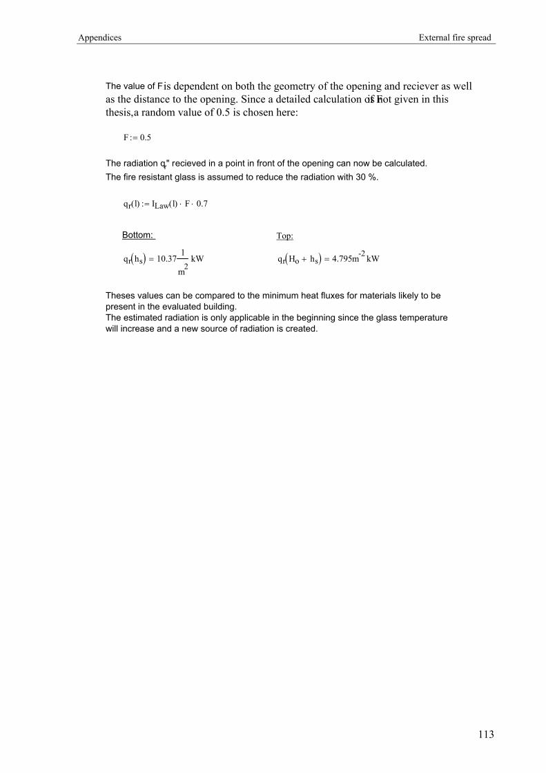
Appendices External fire spread
The value of F is dependent on both the geometry of the opening and reciever as well as the distance to the opening. Since a detailed calculation of F is not given in this thesis, a random value of 0.5 is chosen here:
F 0.5:=
The radiation qr" recieved in a point in front of the opening can now be calculated.The fire resistant glass is assumed to reduce the radiation with 30 %.
qr l( ) ILaw l( ) F⋅ 0.7⋅:=
Bottom: Top:
qr hs( ) 10.371
m2kW= qr Ho hs+( ) 4.795m-2 kW=
Theses values can be compared to the minimum heat fluxes for materials likely to be present in the evaluated building.The estimated radiation is only applicable in the beginning since the glass temperature will increase and a new source of radiation is created.
113


