Page 1
APPLICATION OF HYBRID ENERGY STORAGE TO
IMPROVE THE POWER QUALITY OF DOUBLY FED
INDUCTION GENERATOR BASED WIND SYSTEM
A Dissertation
Submitted in partial fulfillment of the requirement for the
award of the degree of
MASTER OF ENGINEERING
In
POWER SYSTEM AND POWER ELECTRONICS
(ELECTRICAL AND ELECTRONICS ENGINEERING)
By
RUBY TRIPATHI 1602-13-766-022
Under the Guidance of
Mr. M. Sreenivasulu
Assistant Professor (Sr. Sl.),
DEPARTMENT
OF
ELECTRICAL AND ELECTRONICS ENGINEERING
VASAVI COLLEGE OF ENGINEERING
(Affiliated to Osmania University)
Ibrahimbagh, Hyderabad – 500031
2014 – 2015
Page 2
Department of Electrical and Electronics Engineering
Vasavi College of Engineering
Osmania University
CERTIFICATE
This is to certify that the project work entitled “APPLICATION OF HYBRID
ENERGY STORAGE TO IMPROVE THE POWER QUALITY OF DOUBLY
FED INDUCTION GENERATOR BASED WIND SYSTEM” submitted by
RUBY TRIPATHI (1602 – 13 – 766 – 022), a student of Department of Electrical
and Electronics Engineering, Vasavi College of Engineering in partial fulfilment of
the requirements for the award of the degree of Master of Engineering with Power
System and Power Electronics as specialization is a record of the bonafide work
carried out by her during the academic year 2014 – 2015.
Signature of Internal Guide Signature of Head of the Department
Mr. M. Sreenivasulu Mr. K. V. Ramana Murthy
Assistant Professor (Sr. Sl.), Professor & HOD, EEE
Vasavi college of Engineering Vasavi college of Engineering
Hyderabad Hyderabad
Page 3
DECLARATION
I declare that the work reported in the thesis entitled “APPLICATION OF
HYBRID ENERGY STORAGE TO IMPROVE THE POWER QUALITY OF
DOUBLY FED INDUCTION GENERATOR BASED WIND SYSTEM” is a
record of the work done by me in the Department of Electrical and Electronics
Engineering, Vasavi College of Engineering.
No part of the thesis is copied from books/journals/internet and wherever
referred, the same has been duly acknowledged in the text. The reported data are
based on the project work done entirely by me and not copied from any other source.
Signature of the Student
Name: Ruby Tripathi
Reg. no: 1602 – 13 – 766 – 022
Page 4
ACKNOWLEDGEMENT
I would like to express my profound gratitude towards Mr. M. Sreenivasulu
Assistant Professor (Sr. Sl.), of the EEE who played a supervisory role to utmost
perfection, enabled me to seek through M.E and for guiding as an internal guide
methodically and meticulously.
I am grateful to Dr. M. Chakravarthy, Professor for his valuable suggestions
and comments during the research work.
I am highly indebt to Mr K.V. Ramana Murthy, Head of the department,
EEE for his energetic support and providing all the necessary support.
I formally thank the Principal Dr. G. V. Ramana Murthy of Vasavi College
of Engineering for providing all the facilities to complete the M. E. programme.
I would also like to thank Electrical and Electronics Engineering staff for
lending us their time to help us to complete our work successfully.
Ruby Tripathi
(1602 – 13 – 766 – 022)
Page 5
i
ABSTRACT
Over the past 20 years the concern over renewable energy resources is
increasing due to limited conventional resources and increased pollution. In India,
16.8 % of power is contributed by wind energy and with the technological advances
there is a good scope of increasing the power contributed by wind energy. However,
the wind generators when integrated to the grid have adverse effects which lead to the
reduction in power quality. Many researchers have proposed different techniques to
maintain the voltage quality at the PCC by controlling the reactive power. Instead of
controlling the reactive power, an energy storage system can be used to control the
voltage.
The project emphasizes on the application of hybrid energy storage systems to
mitigate the effect of wind speed fluctuations, thereby ensuring smooth power output
as well as improving the power quality at the PCC. To achieve this a control strategy
is designed for managing the demand – generation fluctuations using a hybrid energy
storage system in a wind – dominated remote area power supply system consisting of
a DFIG, a battery / fuel cell storage system , a super capacitor, a dump load and main
loads. Operation of battery / fuel cell storage system is coordinated with a super
capacitor with a view to improving the performance of the battery / fuel cell. In this
model, the battery / fuel cell storage system is connected to the load side of the RAPS
system, whereas the super capacitor is connected to the dc bus of the back – to – back
converter of the DFIG. The models are simulated in Matlab / Simulink environment.
Page 6
ii
TABLE OF CONTENT
ABSTRACT .................................................................................................................. I
LIST OF FIGURES .................................................................................................... V
LIST OF TABLES ................................................................................................... VII
GLOSSARY OF ACRONYM ............................................................................... VIII
LIST OF ABBREVIATIONS .................................................................................... X
CHAPTER 1 ................................................................................................................. 1
INTRODUCTION........................................................................................................ 1
1.1 Introduction to Renewable Energy Resources. .................................................... 1
1.2 Introduction to Wind Energy................................................................................ 2
1.3 Types of Wind Turbine Generators ...................................................................... 4
1.4 Introduction to Storage System ............................................................................ 4
1.4.1 Introduction to Battery................................................................................... 4
1.4.2 Introduction to Super Capacitor .................................................................... 5
1.4.3 Introduction to Fuel cell ................................................................................ 6
1.4.4 Hybrid storage system ................................................................................... 6
1.5 Overveiw .............................................................................................................. 7
1.6 Outline of the Thesis ............................................................................................ 7
CHAPTER 2 ................................................................................................................. 9
LITERATURE SURVEY ............................................................................................ 9
2.1 Electrical Energy and Importance of DFIG ......................................................... 9
2.2 Controlling Schemes and Storage Systems .......................................................... 9
2.3 Chapter Summary ............................................................................................... 10
CHAPTER 3 ............................................................................................................... 11
DFIG OPERATION AND CONTROLLING ......................................................... 11
3.1 Operation of the DFIG ....................................................................................... 11
3.2 Rotor Side Converter Control ............................................................................ 13
3.3 Line Side Converter Control .............................................................................. 15
3.4 Pitch Angle Control ............................................................................................ 16
3.5 Chapter Summary ............................................................................................... 17
Page 7
iii
CHAPTER 4 ............................................................................................................... 18
PROPOSED MODEL AND ITS DETAILED STUDY .......................................... 18
4.1 Existing Model of RAPS System ....................................................................... 18
4.2 Proposed Model of RAPS System ..................................................................... 19
4.3 A Coordinated Control Approach for Hybrid Energy Storage. ......................... 20
4.4 The Power Management Algorithm. .................................................................. 22
4.5 Battery/Fuel cell Storage Function. .................................................................... 24
4.5.1 Estimation of Battery ................................................................................... 25
4.5.2 Estimation of Fuel Cell ................................................................................ 25
4.6 Super Capacitor and Dump Load. ...................................................................... 26
4.6.1 Estimation of Supercapacitor....................................................................... 28
4.6.2 Dump Load Controller ................................................................................. 29
4.7 Chapter Summary ............................................................................................... 30
CHAPTER 5 ............................................................................................................... 31
SIMULATION MODEL AND RESULTS .............................................................. 31
5.1 Simulation Model with Battery and Super Capacitor as Hybrid Storage System
.................................................................................................................................. 31
5.1.1 RSC and LSC Design. ................................................................................. 33
5.1.2 Battery/fuel cell, Supercapacitor and Dump Load Contol .......................... 35
5.2 Simulation Model with fuel cell and Super Capacitor as Hybrid Energy Storage
.................................................................................................................................. 35
5.3 Performance of the Hybrid Energy Storage System Based DFIG System. ....... 37
5.3.1 Battery and super capacitor results .............................................................. 37
5.3.2 Fuel cell and super capacitor results ............................................................ 43
5.3.2.1 Results with Constant Load .................................................................. 43
5.3.2.2 Results with Variable Load ................................................................... 48
5.4 Comparison of Battery and Fuel cell as Storage Systems. ................................. 54
5.5 Chapter Summary ............................................................................................... 54
CHAPTER 6 ............................................................................................................... 56
CONCLUSION AND FUTURE SCOPE ................................................................. 56
6.1 Conclusion .......................................................................................................... 56
6.2 Future Scope ....................................................................................................... 56
Page 8
iv
REFERENCES ........................................................................................................... 58
APPENDIX ................................................................................................................. 60
A.1 Parameters Associated with DFIG Based RAPS System. ................................. 60
Page 9
v
LIST OF FIGURES
Figure 1.1: Renewable energy installed capacity .......................................................... 1
Figure 1.2: India’s wind power installed capacity ......................................................... 3
Figure 1.3: Types of wind turbines ................................................................................ 4
Figure 1.4: Different storage systems ............................................................................ 7
Figure 1.5: Outline of Thesis ......................................................................................... 8
Figure 3.1: DFIG based wind turbine generator system .............................................. 11
Figure 3.2: Super – synchronous mode of operation ................................................... 12
Figure 3.3: Sub – synchronous mode of operation ...................................................... 12
Figure 3.4: RSC control scheme .................................................................................. 15
Figure 3.5: Filter model associated with LSC ............................................................. 15
Figure 3.6: LSC control scheme .................................................................................. 16
Figure 3.7: Pitch angle controlling ............................................................................... 17
Figure 4.1: Existing model of DFIG based RAPS system ........................................... 18
Figure 4.2: Proposed model of DFIG based RAPS system ......................................... 19
Figure 4.3: A Coordinated control approach for hybrid energy storage based RAPS
system ................................................................................................................... 21
Figure 4.4: Estimation of reference power for battery/fuel cell and super capacitor .. 22
Figure 4.5: Operating frequency ranges for storage system ........................................ 23
Figure 4.6: Types of super capacitor............................................................................ 24
Figure 4.7: Inverter control .......................................................................................... 26
Figure 4.8: Buck – Boost converter ............................................................................. 26
Figure 4.9: Super capacitor controlling strategy. ......................................................... 28
Figure 4.10: Dump load control strategy. .................................................................... 29
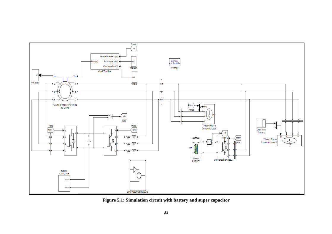
Figure 5.1: Simulation circuit with battery and super capacitor .................................. 32
Figure 5.2: RSC controlling circuit .............................................................................. 33
Figure 5.3: LSC controlling circuit .............................................................................. 34
Figure 5.4: Simulation model with fuel cell and super capacitor ................................ 36
Figure 5.5: Torque and Speed of DFIG ....................................................................... 37
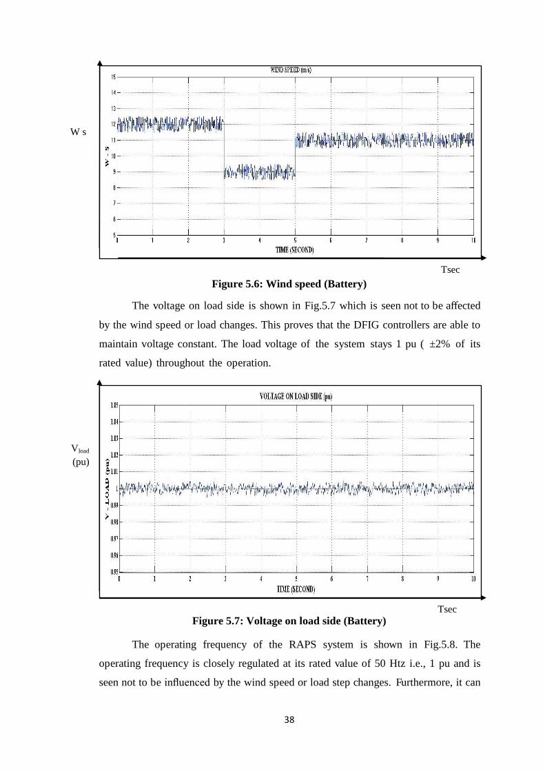
Figure 5.6: Wind speed (Battery)................................................................................. 38
Figure 5.7: Voltage on load side (Battery) ................................................................... 38
Figure 5.8: Frequency on load side (Battery) .............................................................. 39
Page 10
vi
Figure 5.9: DC link Voltage (Battery) ......................................................................... 39
Figure 5.10: Load Demand (Battery) ........................................................................... 40
Figure 5.11: Wind Power (Battery) ............................................................................. 40
Figure 5.12: Hybrid energy storage power .................................................................. 41
Figure 5.13: Dump Load Power (Battery) ................................................................... 41
Figure 5.14: Battery current ......................................................................................... 42
Figure 5.15: Hybrid Energy storage current ................................................................ 42
Figure 5.16: FFT analysis of the battery system .......................................................... 43
Figure 5.17: FFT analysis of the Super capacitor ........................................................ 43
Figure 5.18: Wind Speed ( Fuel cell) ........................................................................... 44
Figure 5.19: Voltage on load side (Fuel cell) .............................................................. 44
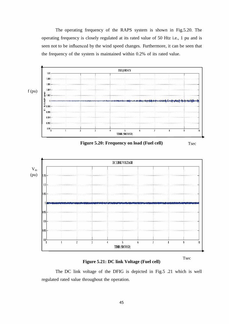
Figure 5.20: Frequency on load (Fuel cell) .................................................................. 45
Figure 5.21: DC link Voltage (Fuel cell) ..................................................................... 45
Figure 5.22: Load Demand (Fuel cell) ......................................................................... 46
Figure 5.23: Wind Power (Fuel cell) ........................................................................... 46
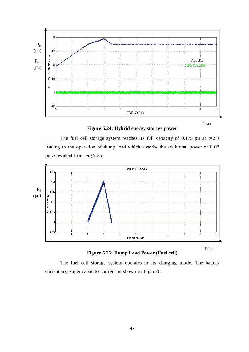
Figure 5.24: Hybrid energy storage power .................................................................. 47
Figure 5.25: Dump Load Power (Fuel cell) ................................................................. 47
Figure 5.26: Hybrid Energy storage current ................................................................ 48
Figure 5.27: Wind Speed (Fuel cell) ............................................................................ 48
Figure 5.28: Voltage on Load Side (Fuel cell) ............................................................ 49
Figure 5.29: Frequency on Load Side (Fuel cell) ........................................................ 49
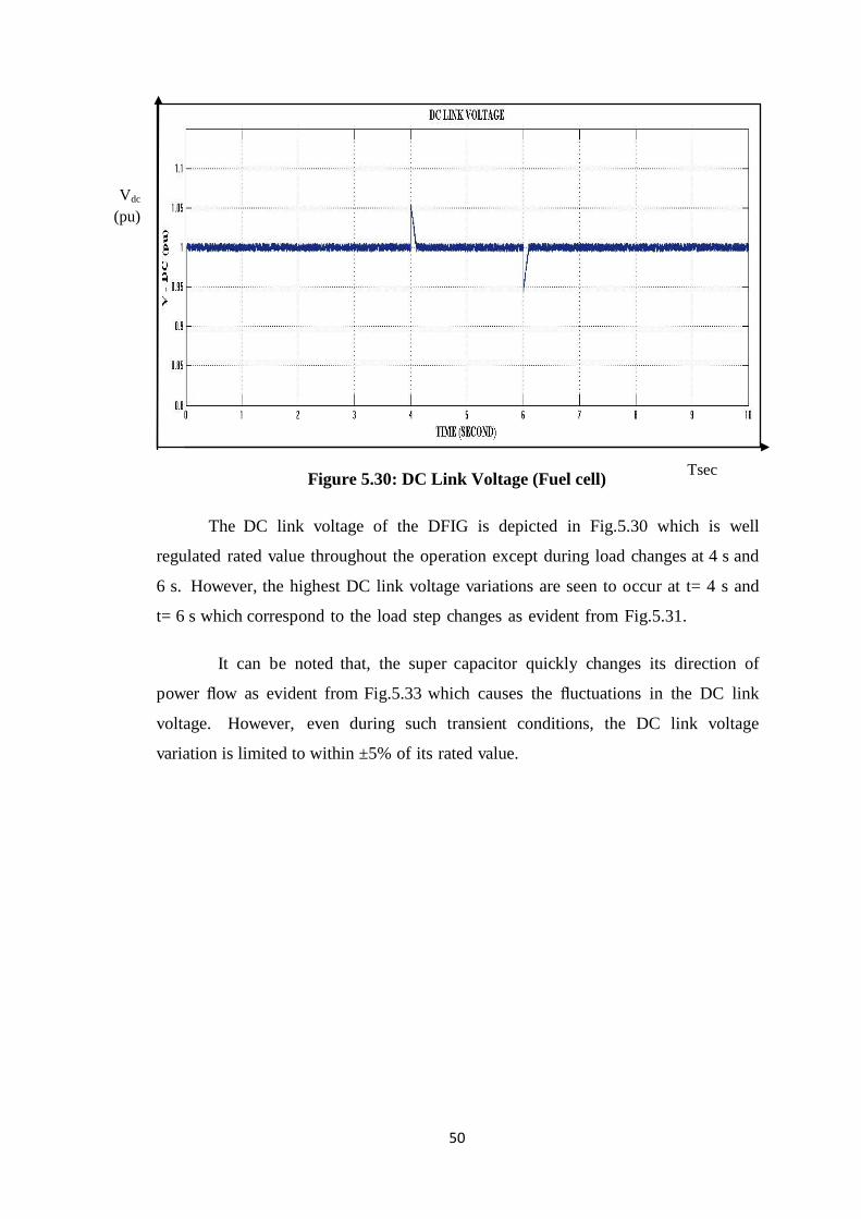
Figure 5.30: DC Link Voltage (Fuel cell) .................................................................... 50
Figure 5.31: Load Demand (Fuel cell) ......................................................................... 51
Figure 5.32: Wind Power (Fuel cell) ........................................................................... 51
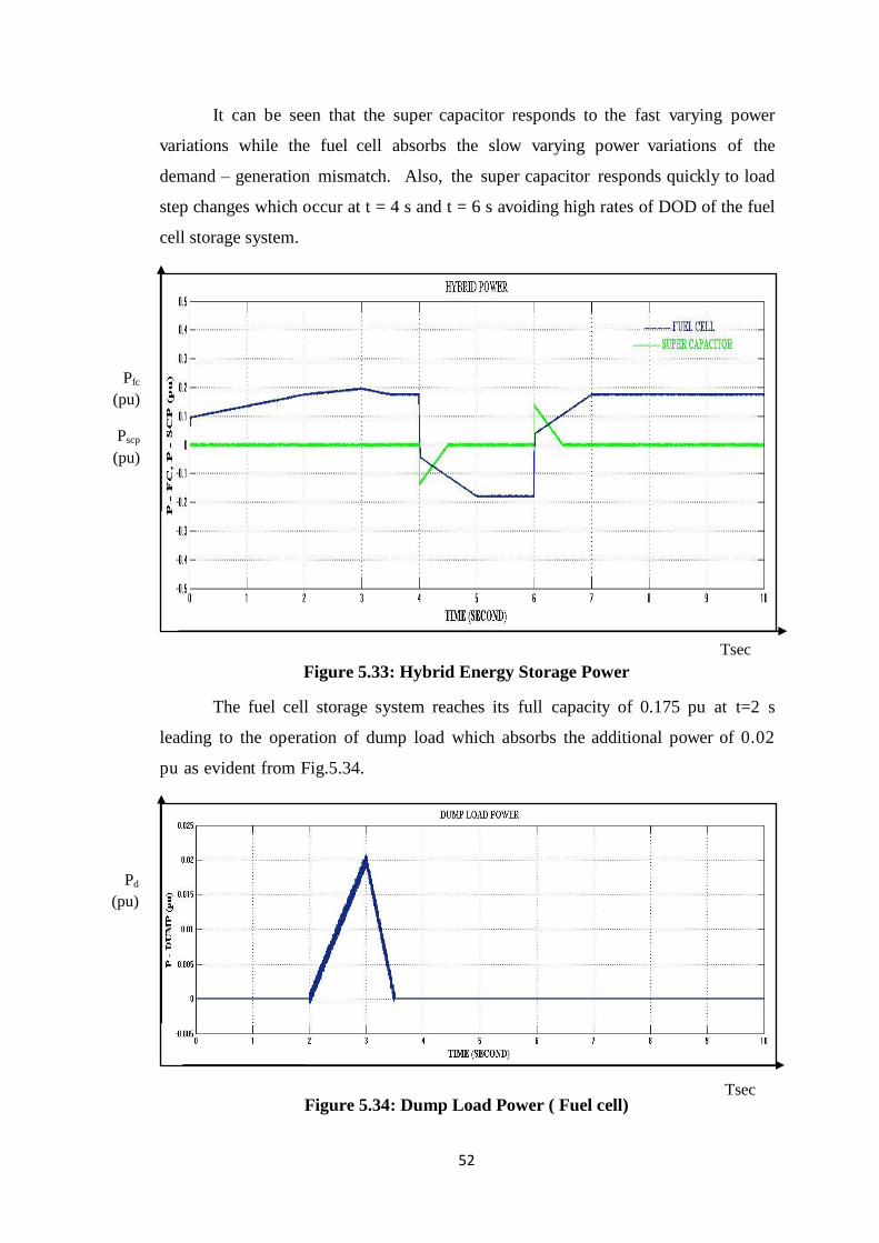
Figure 5.33: Hybrid Energy Storage Power ................................................................. 52
Figure 5.34: Dump Load Power ( Fuel cell) ................................................................ 52
Figure 5.35: Fuel Cell Current ..................................................................................... 53
Figure 5.36: Hybrid Energy Storage Current ............................................................... 53
Page 11
vii
LIST OF TABLES
Table 1.1: Available Supercapacitors in Market............................................................ 6
Table A.1: Parameters .................................................................................................. 60
Page 12
viii
GLOSSARY OF ACRONYM
ρ Air density in Kgm-3
A Area swept by the rotor blades in m2
ib Battery current
ifc Fuel cell current
Pb Battery power output
Vb Battery voltage
Csup Capacitance of super capacitor in F
(Vw)cut – in Cut – in wind speed in ms-1
(Vw)cut – out Cut – out wind speed in ms-1
D Damping Constant
Vdc DC bus voltage
Pd Dump load power
Vds, Vqs d and q axes voltage on load side
Vdr, Vqr d and q axes voltage on rotor side of the DFIG
Фds, Фqs d and q axes stator flux components of DFIG
Фds, Фqs d and q axes rotor flux components of DFIG
Te Electrical torque of wind turbine generator
F Faraday constant in Ckmol-1
ŋF Faraday efficiency
Lf Filter inductance
∆f Frequency deviation
fs Frequency on load side
σ Leakage factor of DFIG
PL Load demand
Plf, Phf Low and high frequency power component
Lm Magnetising inductance of the DFIG
Pm Mechanical power output of the wind turbine
Qmag No – load reactive power output from DFIG
(Te)opt Optimum torque of the wind turbine generator
(Pw)opt Optimum wind power output
∆p power deviation
Page 13
ix
PDFIG Power output of the DFIG
kp,ki Proportional and integral gains of a PI controller
Фrated Rated flux of the DFIG
Qs Reactive power of the stator of the DFIG
QDFIG Reactive power output from DFIG
Φr Rotor Flux of the DFIG
Rr Rotor resistance of the DFIG
Lr Rotor inductance of the DFIG
Pr Rotor power of the DFIG
ωr Rotor speed of the wind turbine generator
S Slip of the DFIG
Фs stator Flux of the DFIG
Rs Stator resistance of the DFIG
Ls Stator inductance of the DFIG
Psc Super capacitor power output
Pfc Fuel cell power output
ωs Synchronous speed
Vsc Voltage across the super capacitor
Vs Voltage on load side
Pw Wind power output
Vw Wind speed in ms-1
Page 14
x
LIST OF ABBREVIATIONS
DFIG Doubly fed induction generator
SEIG Self excited induction generator
PMSG Permanent magnet synchronous generator
MW Mega Watt
WECS Wind Energy Conversion System
RAPS Remote Area Power Supply
RSC Rotor Side Converter
LSC Line Side Converter
PCC Point of Common Coupling
EMA Energy management algorithm
PLL Phase Locked Loop
DOD Depth of Discharge
PWM Pulse Width Modulation
SOC State of Charge
BESS Battery Energy Storage System
FESS Fuel cell Energy Storage System
HESS Hybrid Energy Storage System
PEMFC Proton Exchange Membrane fuel cells
Page 15
1
CHAPTER 1
INTRODUCTION
Electricity is identified as one key commodity which can be used as a
medium for economic growth in rural and regional areas. According to ministry of
new and renewable energy, country's present installed power generation capacity has
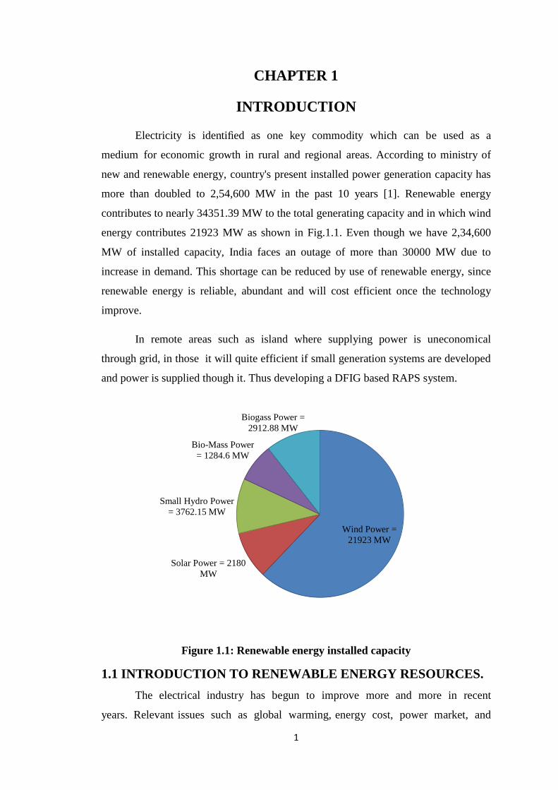
more than doubled to 2,54,600 MW in the past 10 years [1]. Renewable energy
contributes to nearly 34351.39 MW to the total generating capacity and in which wind
energy contributes 21923 MW as shown in Fig.1.1. Even though we have 2,34,600
MW of installed capacity, India faces an outage of more than 30000 MW due to
increase in demand. This shortage can be reduced by use of renewable energy, since
renewable energy is reliable, abundant and will cost efficient once the technology
improve.
In remote areas such as island where supplying power is uneconomical
through grid, in those it will quite efficient if small generation systems are developed
and power is supplied though it. Thus developing a DFIG based RAPS system.
Figure 1.1: Renewable energy installed capacity
1.1 INTRODUCTION TO RENEWABLE ENERGY RESOURCES.
The electrical industry has begun to improve more and more in recent
years. Relevant issues such as global warming, energy cost, power market, and
Wind Power =
21923 MW
Solar Power = 2180
MW
Small Hydro Power
= 3762.15 MW
Bio-Mass Power
= 1284.6 MW
Biogass Power =
2912.88 MW
Page 16
2
increasing energy demand have affected power industry growth. Over the past years,
development of smaller distributed energy sources closer to loads such as Remote
Area Power Supply (RAPS) system has increased. Thus, renewable energy sources
such as wind, solar, biomass, and geothermal are given more importance.
Renewable energy systems offer several advantages over conventional energy
sources such as natural gas or coal. First, renewable energy systems are clean
sources of energy found in most regions, and they do not emit greenhouse gases.
Renewable energy sources are also abundant and free. Although the initial capital
cost for most renewable energy sources is greater than natural gas or coal power
plants, renewable may be more cost – effective for long term as compared to
conventional sources because of lower operating and maintenance costs. However, the
renewable resources have several disadvantages. Primary disadvantage is that they
are mostly available in remote areas at great distances from large loads.
Among all renewable energy options, wind power has gained the importance
as one of the most widespread renewable energy generation technologies. In this
thesis, wind energy is emphasized because it can be used to generate electricity in
remote areas where grid is neither available nor electricity is economical to transfer
via grid.
1.2 INTRODUCTION TO WIND ENERGY.
Wind energy generation began in the 1980s, when wind turbines with only a
few tens of kW rating were connected to power grids without much control. Due to
variations in wind speed, it became difficult in generating power and connecting it
directly to the grid. Furthermore, this system had no control on active and reactive
power transfer. Today, great improvements has been made in wind energy generation
and power electronics devices are used to control and transfer active and reactive
power between wind turbines and grid.
At present wind energy has the greatest share among all other renewable
energy resources. The capacity of wind electrical generation has increased more than
two times and the cost has decreased by one – sixth due to technological
advancements.
Page 17
3
According to the World Wind Energy Report 2014[1], all wind turbines
installed globally by the end of year 2014 contribute potentially 430 Terawatthours
to the worldwide electricity supply which supply 2.5 % of the global electricity
demand per year. India’s wind power installed capacity by the end of March 2015 is
shown in Fig.1.2 which has increased significantly from 1666 MW to 21923 MW.
Figure 1.2: India’s wind power installed capacity
Although wind power generation schemes are seen to offer great
opportunities in supplying power, they encompass many challenges in standalone
mode of operation. Therefore, wind energy based power generating schemes are
always equipped with the power electronic arrangements along with their respective
control techniques.
The use of power electronic interfaces in hybrid RAPS systems creates many
challenges. Firstly, power electronic interfaces lower the overall system inertia which
will adversely affect the voltage and frequency at the customer end. Secondly, the
costs associated with power electronic systems are considerably high. Therefore, it
is important to select the best hybrid RAPS configuration without compromising on
the power quality and reliability [3]. In addition to the above, other challenges
associated with RAPS systems are: (a) coordination of the functions among all
components, and (b) optimising the financial returns. Selection of suitable energy
sources to form a hybrid RAPS system depends entirely on the availability of
resources within the locality. Usually, variable speed wind turbine generator
technologies are preferred in a standalone power system, as they are able to provide
better voltage and frequency regulation when compared to constant speed
generators such as induction generators.
Page 18
4
1.3 TYPES OF WIND TURBINE GENERATORS
There are basically three types of wind generators namely self excited
induction generator (SEIG), doubly fed induction generator (DFIG) and permanent
magnet synchronous generator (PMSG). All the 3 types of generator are shown in
Fig.1.3. In this project, DFIG is used. In DFIG power is fed to both stator and rotor
[3]. The primary advantage of DFIG when compared to other generators is that when
used in wind turbines they allow the amplitude and frequency of their output voltage
to be maintained at a constant value, independent of wind speed.
Figure 1.3: Types of wind turbines
1.4 INTRODUCTION TO STORAGE SYSTEM
In order to maintain smooth power flow with constant voltage and frequency,
RAPS system should be integrated with energy storage system. Ideal energy storage
in a standalone wind energy conversion system should be able to provide both high
energy and power capacities to handle situations such as wind gusts and load step
changes, which may exist for seconds or minutes or even longer. At present, various
types of storage technologies are available to fulfill either power or energy
requirements of a RAPS system. Widely used energy storage technologies that
currently employ in wind farms are batteries, super capacitors, flywheels, compressed
– air energy storage, hydro – pumped storage, superconducting magnetic energy
storage, fuel cells, etc. [10], [11].
1.4.1 INTRODUCTION TO BATTERY
Battery storage was used in the early days of direct – current electric power
networks, and is appearing again. Battery systems connected to large solid – state
converters have been used to stabilize power distribution networks. For example
SEIG PMSG
DFIG
Page 19
5
many "off – the – grid" domestic systems rely on battery storage, but storing large
amounts of electricity in batteries or by other electrical means has not yet been put to
general use.
Batteries are generally expensive, have high maintenance, and have limited
life spans. But one and only possible technology for large – scale storage are batteries.
Nickel – metal – hyderite batteries are not much expensive to implement on a large
scale and have been used for grid storage in Japan and in the United States. Battery
storage has relatively high efficiency, as high as 90% or better.
Rechargeable flow batteries can be used as a rapid – response storage medium.
These storage systems are designed to smooth the transient fluctuations in wind
energy supply.
The advantages of battery are:
They can operate over wide temperature range
They are available in various size.
Depending upon the application, it is possible to charge battery for
long periods of time without self – discharge.
1.4.2 INTRODUCTION TO SUPER CAPACITOR
Supercapacitor is a double layer capacitor in which the energy is stored by
charge transfer at the boundary between electrode and electrolyte. The amount of
stored energy is function of the available electrode and electrolyte surface, the size of
the ions, and the level of the electrolyte decomposition voltage.
Usually supercapacitors are divided into two types: double – layer capacitors
and electrochemical capacitors.
The most important parameters of a super capacitor include the
capacitance(C), ESR and EPR (which is also called leakage resistance). Some of
supercapacitors available in market are shown in Table.1.1.
Page 20
6
Table 1.1: Available Supercapacitors in Market.
S.No Manufacturer Specifications of Supercapacitors
1 Power Star China Make
(single Unit)
50 F/2.7V, 300F/2.7V, 600F/2.7 V, ESR less than
1mΩ.
2 Panasonic Make (Single
Unit) 0.022-70F, 2.1-5.5V, ESR 200 mΩ-350 Ω
3 Maxwell Make
(Module)
63F/125V, 150A ESR 18 mΩ 94F/75 V, 50 A,
ESR 15 mΩ
4 Vinatech Make 10-600F/2.3V, ESR 400 -20 mΩ, 3-350F/2.7,
ESR 90-8 mΩ
5 Nesscap Make (module) 15V/33F, ESR 27 mΩ 340V/ 51F, ESR 19 mΩ
1.4.3 INTRODUCTION TO FUEL CELL
The chemical energy stored in hydrogen and several hydrocarbon fuels is
significantly higher than that found in common battery materials. This leads to the
development of fuel cells for a variety of applications. Fuel cells are an ideal primary
energy conversion device for remote site locations and find application where an
assured electrical supply is required for power generation, remote and uninterruptible
power. The PEMFC Proton exchange Membrane fuel cells are considered to have the
highest energy density of all the fuel cells, and due to the nature of the reaction have
the quickest start up time (less than 1 sec) so they have been favoured for applications
such as vehicles, portable power and backup power applications.
1.4.4 HYBRID STORAGE SYSTEM
In the proposed system, HESS is used. Hybrid energy storage system is a
system which consists of a battery / fuel cell and a super capacitor which are
comparativel good when compared other storing device as shown in Fig.1.4. Among
all energy storage systems, batteries are seen to have one of the highest energy density
levels but not as good as fuel cell i.e., it is able to store for longer periods, whereas the
supercapacitors seem to have the highest power density i.e., they are able to handle
transients that occur over short period of time. At present, battery storage systems are
widely employed in most real– life RAPS applications [12] but fuel cell are taking
over them in coming years.To improve the performance of the battery / fuel cell
energy storage systems, a supercapacitor can be incorporated to perform a hybrid
Page 21
7
operation and the combined energy storage system is able to satisfy both power and
energy requirements of the RAPS system [14], [15]. A power management algorithm
is designed in such a way that the supercapacitor should be able to absorb the ripple
component of demand – generation mismatch.
Figure 1.4: Different storage systems
1.5 OVERVEIW
In this thesis, a simulation model of DFIG based wind dominated RAPS
system is developed. The system is designed in order to maintain the load side
voltage and frequency within acceptable limits during over – generation and under –
generation. To achive this main objective, it is important to manage the active and
reactive power contribution of the components in RAPS system. In this regard,
control coordinated strategies are developed and implemented among the components
present within the RAPS system. In addition, individaul control is developed based on
an appropriate coordinated control approach with a view to regulate the magnitude of
the voltage and freqency on the load side. In this thesis, RAPS systems consisting of
battery / fuel cell storage, super capacitor and dump load are expalined briefly along
with simulation models. A comparison of battery versus fuel cell energy storage
system is done.
1.6 OUTLINE OF THE THESIS
A brief description of the contents of the chapter is given below:
A brief introduction about the project is discussed in chapter 1.
Chapter 2 is a literature survey providing detailed information about the
previous works done in this field.
Page 22
8
In chapter 3, the operating and controlling methods developed for DFIG are
discussed in detail. RSC and LSC controlling techniques are also discussed in
detailed.
In chapter 4, importance of integrating energy storage for wind turbine ,
necessity for supercapacitor for improving the life span of battery and dump load
controlling are discussed in detail.
Chapter 5 gives a detailed study of two simulation models, one with battery
and super capacitor as hybrid storage system and other with fuel cell and super
capacitor as hybrid storage system. Results are discussed in detailed with the
variations in wind and load for both the systems and a comparative study is done.
Finally, chapter 6 summarises the major outcomes of the work presented in
thesis and makes suggestions for future scope.
Figure 1.5: Outline of Thesis
Chapter 1
Introduction
Chapter 2
Literature survey
Chapter 3
DFIG operation and controlling
Chapter 4
Proposed model
Chapter 5
Simulation models and Results
Chapter 6
Conclusion and Future scope
Page 23
9
CHAPTER 2
LITERATURE SURVEY
During the research work, various papers and journals have been reviewed and their
brief overview is presented.
2.1 ELECTRICAL ENERGY AND IMPORTANCE OF DFIG
Paul Cook et al, [2] explains the importance of providing electricity in rural areas. In
this paper author explains about how the electricity leads to the development of rural
area. In this paper author gives importance to both grid and off – grid development
which can also help in generating in – come for rural areas.
S. Muller, M.Deicke, & Rik W.De Doncker et al, [3] explains the importance of
DFIG and its working. The authors’ gives more important to widely used variable –
speed wind – generator concepts are doubly – fed induction generators (DFIG). The
paper explains the working of DFIG and lists out its advantages over other turbine
generators.
Dr John Fletcher and Jin Yang et al, [5] proposed the controlling of DFIG by
employing RSC and LSC converters. The paper explains about the functioning of
RSC and LSC. Authors also explain about the back – to – back arrangement of the
converters. Paper also explains the importance of DC link capacitor which acts as a
link between converters.
2.2 CONTROLLING SCHEMES AND STORAGE SYSTEMS
Ajay Kushwaha, Inderpreet Singh et al, [6] paper explains about the different control
schemes mainly of doubly fed induction generator (DFIG) wind turbine. This paper
gives the proper explanation of control schemes along with their limitations. Working
of DFIG wing turbine not only depends on the type of generator but also on the
control strategies used. Vector control (VC) scheme is used for controlling the DFIG
D. Santos – Martin, S. Arnaltes, and J. L. R. Amenedo et al, [8] paper explains about
the controlling of reactive power output of DFIG based wind turbines.
M. Beaudin, H. Zareipour, A. Schellenberglabe, and W. Rosehart et al, [10] explains
about the importance of storage system and their advantages in improving the power
Page 24
10
quality. Author explains about the battery technology, flywheel technology and
capacitors as storing devices for improving the power quality. The authors also
address about the cost of each devices.
Kuldeep Sahay, Bharti Dwivedi et al, [11] explains about the power quality problem
that affects the operating equipments for end user. RAPS system associated with
serious power qualities issues. The paper focuses on importance of the use of energy
storage devices to improve power quality.
Martin Winter et al, [15] briefly explain about the battery, fuel cell and super
capacitor working and construction. Author also gives a brief description of
advantages and disadvantages of each storing system.
N. Mendis at el, [4] describes the importance of battery storage for maintaining the
power balance between load and source and improving voltage at PCC. The use of
super capacitor for improving battery lifetime is also explained.
In the proposed model battery energy storage system is replaced with Fuel cell Energy
storage system and a comparative analysis is made.
2.3 CHAPTER SUMMARY
This chapter summarizes a brief description of different kinds of work done if
the field of DFIG and RAPS system. The different types of controlling approaches
adopted by different authors for controlling DFIG are explained. An overview of
energy storing systems available in the market is discussed.
Page 25
11
CHAPTER 3
DFIG OPERATION AND CONTROLLING
This chapter presents the relevant study of the DFIG operation and controlling.
Section 3.1 gives a complete study of advantages and operation of DFIG. Section 3.2
explains about RSC controlling. In section 3.3, Controlling of LSC is explained with
necessary contolling scheme. Finally, in section 3.4 Pitch angle controlling is
explained.
3.1 OPERATION OF THE DFIG
In this thesis, DFIG is given much importance because in DFIG power is fed
to both stator and rotor. The primary advantage of DFIG when compared to other
generators is that, when they are used in wind turbines, they allow the amplitude and
frequency of their output voltage to be maintained at a constant value, no matter the
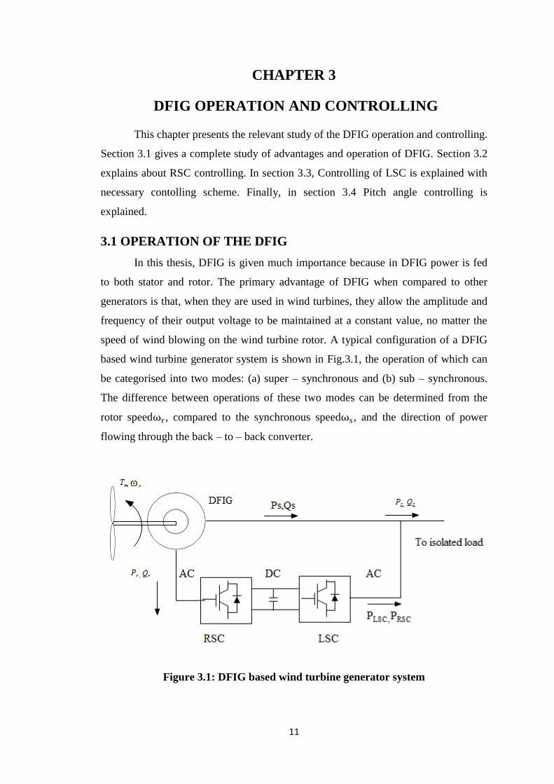
speed of wind blowing on the wind turbine rotor. A typical configuration of a DFIG
based wind turbine generator system is shown in Fig.3.1, the operation of which can
be categorised into two modes: (a) super – synchronous and (b) sub – synchronous.
The difference between operations of these two modes can be determined from the
rotor speedωr , compared to the synchronous speedωs , and the direction of power
flowing through the back – to – back converter.
Figure 3.1: DFIG based wind turbine generator system
Page 26
12
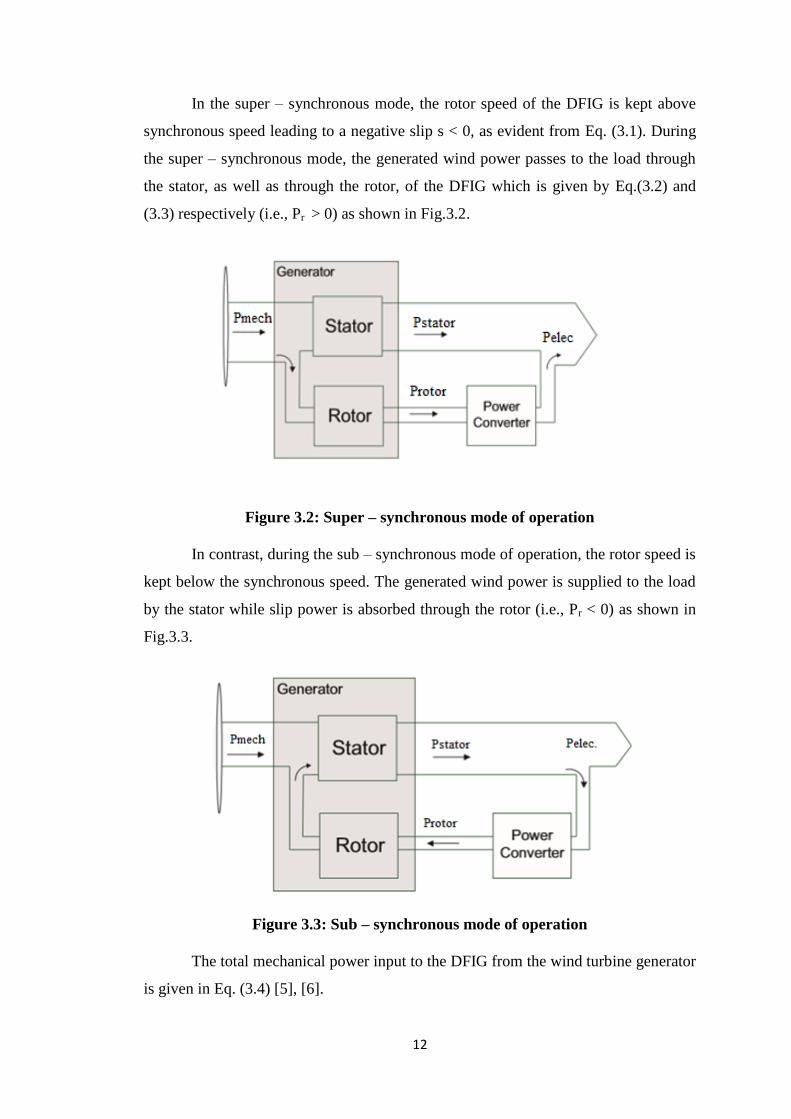
In the super – synchronous mode, the rotor speed of the DFIG is kept above
synchronous speed leading to a negative slip s < 0, as evident from Eq. (3.1). During
the super – synchronous mode, the generated wind power passes to the load through
the stator, as well as through the rotor, of the DFIG which is given by Eq.(3.2) and
(3.3) respectively (i.e., Pr > 0) as shown in Fig.3.2.
Figure 3.2: Super – synchronous mode of operation
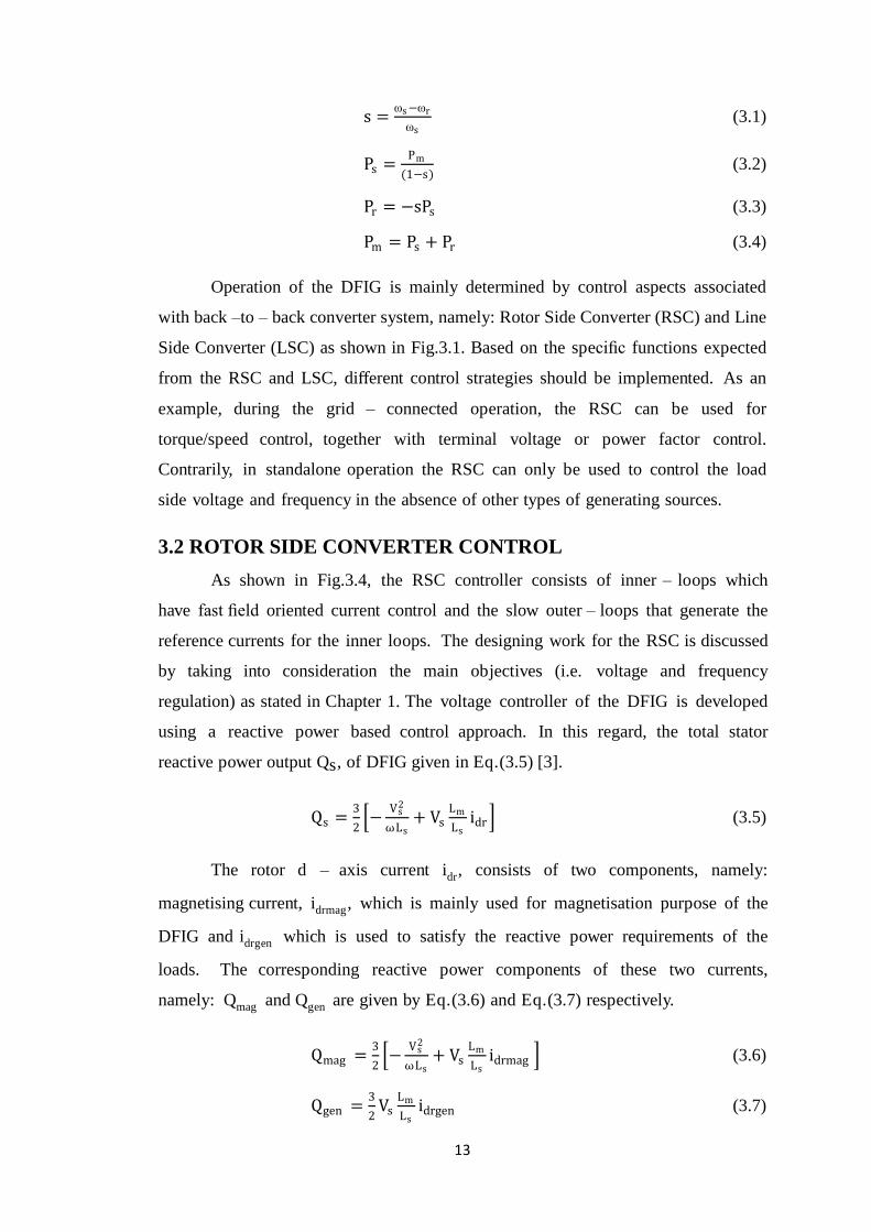
In contrast, during the sub – synchronous mode of operation, the rotor speed is
kept below the synchronous speed. The generated wind power is supplied to the load
by the stator while slip power is absorbed through the rotor (i.e., Pr < 0) as shown in
Fig.3.3.
Figure 3.3: Sub – synchronous mode of operation
The total mechanical power input to the DFIG from the wind turbine generator
is given in Eq. (3.4) [5], [6].
Page 27
13
s =ωs −ωr
ωs (3.1)
Ps =Pm
(1−s) (3.2)
Pr = −sPs (3.3)
Pm = Ps + Pr (3.4)
Operation of the DFIG is mainly determined by control aspects associated
with back –to – back converter system, namely: Rotor Side Converter (RSC) and Line
Side Converter (LSC) as shown in Fig.3.1. Based on the specific functions expected
from the RSC and LSC, different control strategies should be implemented. As an
example, during the grid – connected operation, the RSC can be used for
torque/speed control, together with terminal voltage or power factor control.
Contrarily, in standalone operation the RSC can only be used to control the load
side voltage and frequency in the absence of other types of generating sources.
3.2 ROTOR SIDE CONVERTER CONTROL
As shown in Fig.3.4, the RSC controller consists of inner – loops which
have fast field oriented current control and the slow outer – loops that generate the
reference currents for the inner loops. The designing work for the RSC is discussed
by taking into consideration the main objectives (i.e. voltage and frequency
regulation) as stated in Chapter 1. The voltage controller of the DFIG is developed
using a reactive power based control approach. In this regard, the total stator
reactive power output Qs, of DFIG given in Eq.(3.5) [3].
Qs =3
2 −
Vs2
ωLs+ Vs
Lm
Lsidr (3.5)
The rotor d – axis current idr, consists of two components, namely:
magnetising current, idrmag, which is mainly used for magnetisation purpose of the
DFIG and idrgen which is used to satisfy the reactive power requirements of the
loads. The corresponding reactive power components of these two currents,
namely: Qmag and Qgen are given by Eq.(3.6) and Eq.(3.7) respectively.
Qmag =3
2 −
Vs2
ωLs+ Vs
Lm
Lsidrmag (3.6)
Qgen =3
2Vs
Lm
Lsidrgen (3.7)
Page 28
14
The no – load reactive power can be compensated by imposing the condition
given by Eq.(3.8). In addition, the reference current of idrgen can be established by
considering the voltage error which is compensated through a PI controller as in
Eq.(3.9). Therefore, the reference d – axis component of the current which is used to
satisfy the magnitude of the stator voltage can be given as in Eq.(3.10).
idrmag =Vs
ωLm (3.8)
(idrgen ω)ref = Kp + Ki ((Vs)ref − Vs ) (3.9)
(idr )ref = (idrgen )ref + idrmag (3.10)
where, kp and ki are proportional and integral gains of the PI controller respectively.
The stator flux orientation scheme for the machine is ensured by setting the
q – axis component of the stator flux to zero. Mathematically this condition can be
given as in Eq.(3.11) and is regarded as a criterion which needs to be followed by the
DFIG in order to regulate the frequency at the stator or load side.
iqr = −Ls
Lmiqs (3.11)
Therefore, q – axis component of the rotor current given in Eq.(3.11) is
considered as the reference q – axis component of the rotor current which is used to
achieve frequency regulation. In addition, a virtual phase lock loop (PLL) is used to
define the reference frequency for the entire control scheme of the RSC as shown in
Fig.3.5.
RSC control algorithm is implemented by mainly considering the conditions
given in E q . (3.10) , which are used to define the d and q axes reference currents
respectively for the inner – loop controllers as shown in Fig.3.4. These reference
currents are compared with the actual rotor currents, idr and iqr and the error signals
are then compensated using the PI controllers to generate the switching signals for
the RSC. The entire control structure associated with RSC is shown in Fig.3 . 4 .
Page 29
15
Figure 3.4: RSC control scheme
3.3 LINE SIDE CONVERTER CONTROL
The LSC is used to control the DC bus voltage of the back – to – back
converter system and to supply any reactive power to the loads if needed. In this
regard, the L – R filter model shown in Fig.3.5 is used to develop the model of the
controllers for LSC.
Figure 3.5: Filter model associated with LSC
The control scheme of LSC consists of a fast inner current control loop which
controls the current through the filter circuit given in Fig.3.5. The outer slower
control loops are used to regulate the DC bus voltage of the back – to – back
converter and control reactive power supply through LSC.
Page 30
16
PLSC =3
2Vds ids (3.12)
QLSC =3
2Vds iqs (3.13)
With reference to Eq.(3.12) and Eq.(3.13), it is evident that the d and q
axes components of currents through filter can be used to regulate the DC link
voltage and reactive power supply to the loads respectively. There is a possibility of
supplying reactive power through LSC to a static synchronous compensator
(STATCOM). In the present work, the reactive power reference Qref is set at zero.
The corresponding control scheme implemented for LSC is shown in Fig.3.6.
Figure 3.6: LSC control scheme
3.4 PITCH ANGLE CONTROL
A pitch angle regulator can be regarded as a mechanical control scheme that
can be utilised to limit: (a) power output and (b) speed of a wind turbine
generator. Although variable speed wind turbine generators allow operation under
different speeds, there is a maximum safe operating speed limit for each type of
generator (e.g. the maximum speed of a DFIG based wind turbine is limited to
1.2 or 1.3 pu of its rated speed). If the wind turbine generator exceeds the
maximum speed limit, pitch regulation can be employed in a manner that the power
output of the wind turbine generator is regulated by adjusting the angle of the
turbine blades to compensate for wind speed variations.
Page 31
17
Figure 3.7: Pitch angle controlling
There are various pitch regulation schemes employing for wind turbine
generators. The adopted pitch regulation control scheme is shown in Fig.3.8. The
pitch controller computes pitch angle β by comparing the difference between the
maximum speed (ωr)max, and operating speed ωr.
However, the pitch angle controller is a mechanically controlled mechanism
which cannot be effectively utilised to limit the power output of the wind turbine
generator quickly due to slower mechanical dynamics. As an alternative solution,
a dump load can be employed into a RAPS system.
3.5 CHAPTER SUMMARY
This chapter explained about the DFIG operation and its controlling. Rotor
side converter and Line side converter operation was also explained along with their
controlling schemes. The controlling implemented is flux oriented vector control and
pitch angle controlling is also studied.
Page 32
18
CHAPTER 4
PROPOSED MODEL AND ITS DETAILED STUDY
This chapter presents the relevant study of the proposed model. Section 4.1
gives a complete study of existing model of DFIG based wind dominated remote area
power supply (RAPS) system using hybrid (battery and supercapacitor) energy
storage. In section 4.2, proposed model that is developed is discussed in detail. In
section 4.3, a coordinated control approach for hybrid enegy storage based RAPS
system is discussed. Section 4.4 describes the power management algorithm for
hybrid energy storage system. Section 4.5 describes fuel cell storage function. Finally
in section 4.5, function of super capacitor and dump load is explained along with
controlling schemes.
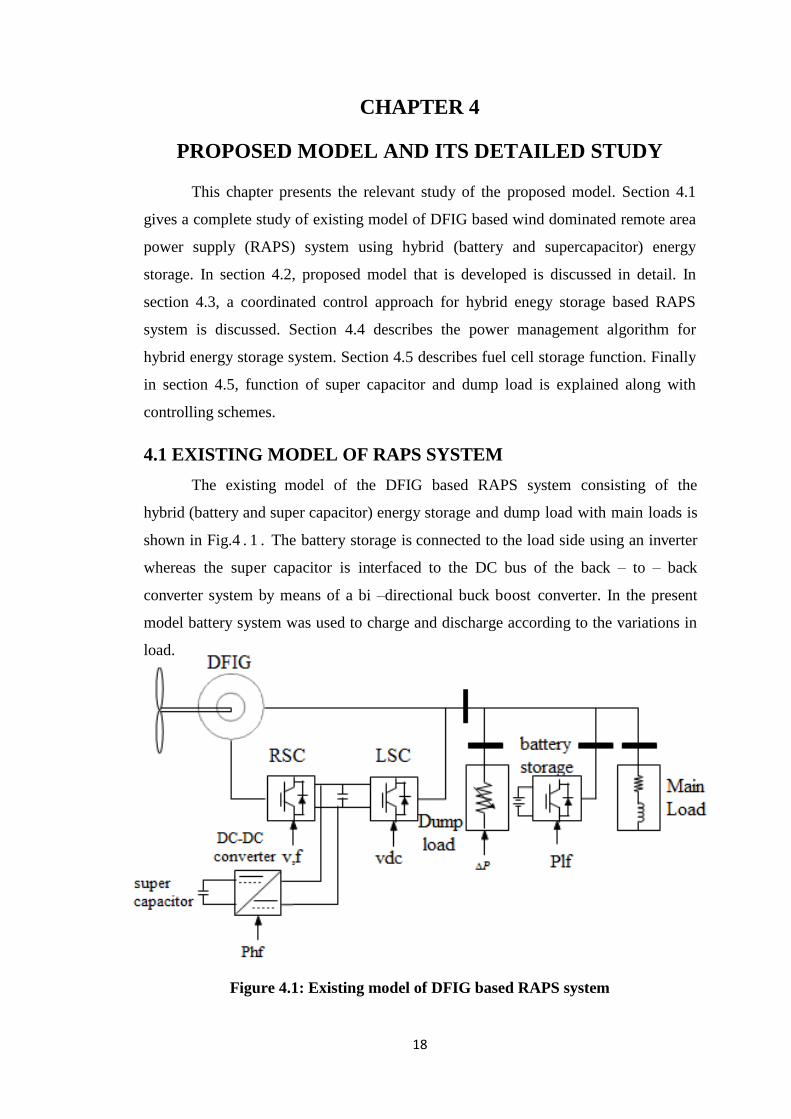
4.1 EXISTING MODEL OF RAPS SYSTEM
The existing model of the DFIG based RAPS system consisting of the
hybrid (battery and super capacitor) energy storage and dump load with main loads is
shown in Fig.4 . 1 . The battery storage is connected to the load side using an inverter
whereas the super capacitor is interfaced to the DC bus of the back – to – back
converter system by means of a bi –directional buck boost converter. In the present
model battery system was used to charge and discharge according to the variations in
load.
Figure 4.1: Existing model of DFIG based RAPS system
Page 33
19
The battery that is used is NiMH, which is capable of delivering high
discharge current, but repeated discharges of high load currents reduces the battery’s
life cycle. These limitations of batteries lead to its replacement with fuel cell.
4.2 PROPOSED MODEL OF RAPS SYSTEM
The proposed model with hybrid (Fuel cell and super capacitor) energy storage
and dump load with main loads is shown in Fig.4 . 2 . The fuel cell storage is
connected to the load side using an inverter whereas the super capacitor is interfaced
to the DC bus of the back – to – back converter system by means of a bi –directional
buck boost converter.
The operation of the entire RAPS system is designed according to the
coordinated control approach given in Fig.4 . 3 .T he energy management algorithm
is developed for the hybrid energy storage system based on the operating frequency
of battery/fuel cell storage and super capacitor as it is shown in Fig.4.4, which is
taken as the basis for the development of the controllers associated with the power
electronic interfaces.
The control strategies that are used to control the back – to – back converter
system of the DFIG are the same as which were illustrated in Section 3.2 and 3.3 of
Chapter 3. The control strategies associated with the battery/fuel cell storage system,
super capacitor and dump load are explained in the following sections.
Figure 4.2: Proposed model of DFIG based RAPS system
Page 34
20
4.3 A COORDINATED CONTROL APPROACH FOR HYBRID
ENERGY STORAGE.
The decision – making process associated with the control coordination
algorithm of the wind – battery/fuel cell – supercapacitor – based RAPS system is
shown in Fig.4.3. During over generation condition where the power output from the
wind turbine generator Pw is greater then the load demand PL, the hybrid energy
storage Pb (i.e., battery/fuel cell storage and super capacitor) absorbs the excess power
(PW – PL ) and it is shared between the battery/fuel cell storage system and super
capacitor according to the power management algorithm.
If the capacity of the hybrid energy storage system reaches the maximum limit
or (Pb)max, the dump load needs to absorb the excess power. However, if the dump
load power Pd reaches its maximum limit rating (Pd) max, the pitch angle control has to
be activated in order to reduce the power output of the wind turbine generator.
During under generation situations where the power output of the wind
turbine generator is less than the load demand, i.e., (PW – PL ) < 0, it is assumed that
the hybrid energy storage Pb is able to supply the required power deficit (PL – PW).
During emergency situations such as no power output from wind turbine
generator due to wind speed being below cut – in level or above cut – out level, a load
shedding scheme can be implemented. Moreover, the proposed control coordination
concept has been realized by developing the control strategies for each component of
the RAPS system.
Page 35
21
Figure 4.3: A Coordinated control approach for hybrid energy storage based
RAPS system
Power management algorithm
Wind Power
Pw
Vcut-in<V<Vcut-out
Pw-PL>0
Pw=0
Hybrid energy
storage system-
discharging
Pw+Pb+Psc
-PL>0
Load
shedding
Hybrid energy storage
system-battery/fuel cell
charging
Battery/Fuel cell
– low frequency
component
Super capacitor
–high frequency component
Pb<(Pb)max Dump
Load
“ON”
Pd <(Pd)max Pitch
Regulation
Frequency
control
NO
NO
NO
NO
NO
Battery/Fuel cell discharging
Battery/Fuel cell
charging
Yes
Yes
Yes
Yes
Yes
Page 36
22
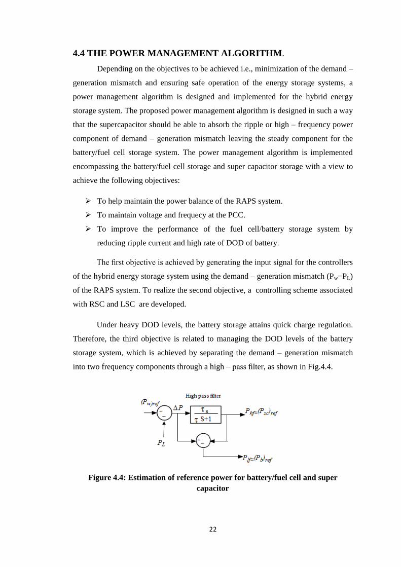
4.4 THE POWER MANAGEMENT ALGORITHM.
Depending on the objectives to be achieved i.e., minimization of the demand –
generation mismatch and ensuring safe operation of the energy storage systems, a
power management algorithm is designed and implemented for the hybrid energy
storage system. The proposed power management algorithm is designed in such a way
that the supercapacitor should be able to absorb the ripple or high – frequency power
component of demand – generation mismatch leaving the steady component for the
battery/fuel cell storage system. The power management algorithm is implemented
encompassing the battery/fuel cell storage and super capacitor storage with a view to
achieve the following objectives:
To help maintain the power balance of the RAPS system.
To maintain voltage and frequecy at the PCC.
To improve the performance of the fuel cell/battery storage system by
reducing ripple current and high rate of DOD of battery.
The first objective is achieved by generating the input signal for the controllers
of the hybrid energy storage system using the demand – generation mismatch (Pw−PL)
of the RAPS system. To realize the second objective, a controlling scheme associated
with RSC and LSC are developed.
Under heavy DOD levels, the battery storage attains quick charge regulation.
Therefore, the third objective is related to managing the DOD levels of the battery
storage system, which is achieved by separating the demand – generation mismatch
into two frequency components through a high – pass filter, as shown in Fig.4.4.
Figure 4.4: Estimation of reference power for battery/fuel cell and super
capacitor
Page 37
23
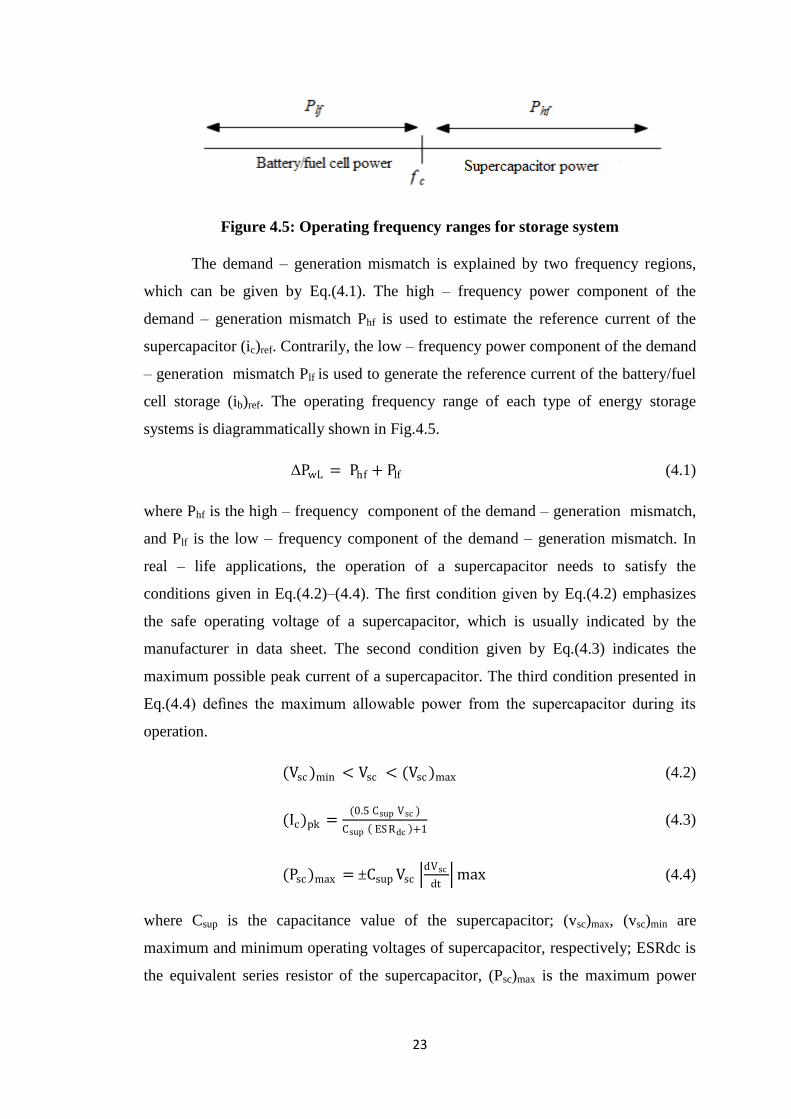
Figure 4.5: Operating frequency ranges for storage system
The demand – generation mismatch is explained by two frequency regions,
which can be given by Eq.(4.1). The high – frequency power component of the
demand – generation mismatch Phf is used to estimate the reference current of the
supercapacitor (ic)ref. Contrarily, the low – frequency power component of the demand
– generation mismatch Plf is used to generate the reference current of the battery/fuel
cell storage (ib)ref. The operating frequency range of each type of energy storage
systems is diagrammatically shown in Fig.4.5.
ΔPwL = Phf + Plf (4.1)
where Phf is the high – frequency component of the demand – generation mismatch,
and Plf is the low – frequency component of the demand – generation mismatch. In
real – life applications, the operation of a supercapacitor needs to satisfy the
conditions given in Eq.(4.2)–(4.4). The first condition given by Eq.(4.2) emphasizes
the safe operating voltage of a supercapacitor, which is usually indicated by the
manufacturer in data sheet. The second condition given by Eq.(4.3) indicates the
maximum possible peak current of a supercapacitor. The third condition presented in
Eq.(4.4) defines the maximum allowable power from the supercapacitor during its
operation.
(Vsc )min < Vsc < (Vsc )max (4.2)
(Ic)pk =(0.5 Csup Vsc )
Csup ES Rdc +1 (4.3)
(Psc )max = ±Csup Vsc dVsc
dt max (4.4)
where Csup is the capacitance value of the supercapacitor; (vsc)max, (vsc)min are
maximum and minimum operating voltages of supercapacitor, respectively; ESRdc is
the equivalent series resistor of the supercapacitor, (Psc)max is the maximum power
Page 38
24
rating of the capacitor, and dVsc
dt max is the maximum rate of change of voltage
across the supercapacitor.
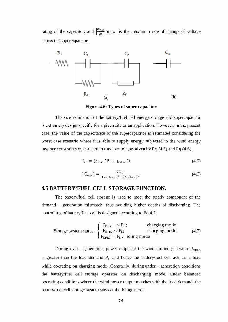
Figure 4.6: Types of super capacitor
The size estimation of the battery/fuel cell energy storage and supercapacitor
is extremely design specific for a given site or an application. However, in the present
case, the value of the capacitance of the supercapacitor is estimated considering the
worst case scenario where it is able to supply energy subjected to the wind energy
inverter constraints over a certain time period t, as given by Eq.(4.5) and Eq.(4.6).
Esc = (Smax (PDFIG )rated )t (4.5)
( Csup ) =2Esc
((Vsc )max )2−((Vsc )min )2
(4.6)
4.5 BATTERY/FUEL CELL STORAGE FUNCTION.
The battery/fuel cell storage is used to meet the steady component of the
demand – generation mismatch, thus avoiding higher depths of discharging. The
controlling of battery/fuel cell is designed according to Eq.4.7.
Storage system status =
PDFIG > PL ; charging mode PDFIG < PL; charging mode
PDFIG = PL ; idling mode
(4.7)
During over – generation, power output of the wind turbine generator PDF IG
is greater than the load demand PL and hence the battery/fuel cell acts as a load
while operating on charging mode .Contrarily, during under – generation conditions
the battery/fuel cell storage operates on discharging mode. Under balanced
operating conditions where the wind power output matches with the load demand, the
battery/fuel cell storage system stays at the idling mode.
(a) (b)
Page 39
25
As shown in Fig.4.1 and Fig.4.2, an inverter is used to interface the
battery/fuel cell storage system with the RAPS system. The inverter control associated
with the storage system is developed by following the power management algorithm
and depicted in Fig.4.7. The reference current of the (ib)ref is generated considering
the low – frequency component of the demand – generation mismatch Plf, as given in
Eq.(4.8). The inverter is operated at unity power factor by setting (iqs)ref equal to zero.
(Ib)ref = (Plf + Pb)(kp +ki
s) (4.8)
where Pb is the actual power, and kp and ki are the proportional and integral
gains of the PI controller, respectively.
4.5.1 ESTIMATION OF BATTERY
The capacity estimation of the battery storage system depends on many factors
such as wind profile and load demand. The size of the battrey system is estimated
using Eq.(4.9)
μ × irated × t
60 = (Ah rating) × k′ (4.9)
where, μ is fraction of the rated current of the load demand, irated is the rated curent
corresponding to load demand, t is the time duration over which the battery provides
power to the system, k′ is the average discharge/charge current of the battery storage
in pu.
4.5.2 ESTIMATION OF FUEL CELL
The estimation of the size of a fuel cell system is extremely application
specific and depends on many factors such as wind profile and wind generator
capacity. In this thesis, the fuel cell system is sized to provide 25% of the rated load
demand which also satisfies the constrains associated with the rating of inverter.
Page 40
26
Figure 4.7: Inverter control
4.6 SUPER CAPACITOR AND DUMP LOAD.
The low – frequency model of a supercapacitor consisting of a capacitor,
which can be used under power system operating frequency range, is employed in the
project. The super capacitor system is connected to the DC bus using a bi –
directional buck – boost converter as shown in Fig.4.8.
Figure 4.8: Buck – Boost converter
Page 41
27
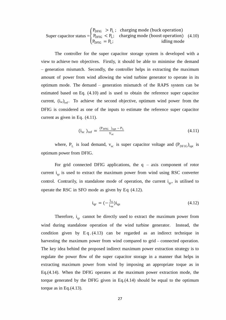
Super capacitor status =
PDFIG > PL ; charging mode (buck operation) PDFIG < PL ; charging mode (boost operation)PDFIG = PL ; idling mode
(4.10)
The controller for the super capacitor storage system is developed with a
view to achieve two objectives. Firstly, it should be able to minimise the demand
– generation mismatch. Secondly, the controller helps in extracting the maximum
amount of power from wind allowing the wind turbine generator to operate in its
optimum mode. The demand – generation mismatch of the RAPS system can be
estimated based on Eq. (4.10) and is used to obtain the reference super capacitor
current, (isc)ref . To achieve the second objective, optimum wind power from the
DFIG is considered as one of the inputs to estimate the reference super capacitor
current as given in Eq. (4.11).
(isc )ref = (PDFIG )opt − PL
Vsc (4.11)
where, PL is load demand, vsc is super capacitor voltage and (PDF IG)opt is
optimum power from DFIG.
For grid connected DFIG applications, the q – axis component of rotor
current iqr is used to extract the maximum power from wind using RSC converter
control. Contrarily, in standalone mode of operation, the current iqr, is utilised to
operate the RSC in SFO mode as given by Eq (4.12).
iqr = (−Ls
Lm)iqs (4.12)
Therefore, iqr cannot be directly used to extract the maximum power from
wind during standalone operation of the wind turbine generator. Instead, the
condition given by E q . (4.13) can be regarded as an indirect technique in
harvesting the maximum power from wind compared to grid – connected operation.
The key idea behind the proposed indirect maximum power extraction strategy is to
regulate the power flow of the super capacitor storage in a manner that helps in
extracting maximum power from wind by imposing an appropriate toque as in
Eq.(4.14). When the DFIG operates at the maximum power extraction mode, the
torque generated by the DFIG given in Eq.(4.14) should be equal to the optimum
torque as in Eq.(4.13).
Page 42
28
As evident from Eq.(4.15), the maximum power extraction from DFIG can
be realised by varying iqs, the q – axis component of the stator current. Therefore,
by allowing the super capacitor current as given in Eq.(4.16), it is possible to vary iqs
resulting DFIG to operate on maximum power extraction mode.
(Te)opt = Kopt (ωr)2 (4.13)
Te =Lm
Ls +Lm
Vs
ωr iqr (4.14)
ωr = (Lm Vs
(Ls +Lm )Kopt) iqs (4.15)
where, Te is electromagnetic torque of the DFIG, iqr, iqs are rotor and stator
q-axis currents respectively, Ls, Lm are stator inductance and magnetising
inductance respectively.
(isc )ref =Phf
Vsc (4.16)
Therefore the high – frequency component of the demand – generation
mismatch Phf is met by the supercapacitor where the corresponding reference current
(isc)ref is estimated using Eq. (4.16). The adopted control strategy for the
supercapacitor is illustrated in Fig.4.9.
Figure 4.9: Super capacitor controlling strategy.
4.6.1 ESTIMATION OF SUPERCAPACITOR
The supercapacitor is used to supply smax times the rated capacity of the DFIG
power, i.e., PDFIG. The safe operating voltage limits associated with the supercapacitor
are selected to be as follows:
250 V < vsc < 500 V (4.17)
Page 43
29
Assuming that, in the worst case, the supercapacitor is able to provide the
maximum slip power of DFIG smax PDFIG for time t = 10s, the capacitance value of the
supercapacitor can be calculated as follows:
C=(Smax (PDFIG )rated )t
((Vsc )max )2−((Vsc )min )2 (4.18)
C=(3×750×1000×10×2)
(5002−2002)≈ 20F (4.19)
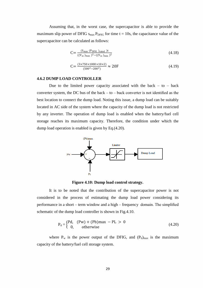
4.6.2 DUMP LOAD CONTROLLER
Due to the limited power capacity associated with the back – to – back
converter system, the DC bus of the back – to – back converter is not identified as the
best location to connect the dump load. Noting this issue, a dump load can be suitably
located in AC side of the system where the capacity of the dump load is not restricted
by any inverter. The operation of dump load is enabled when the battery/fuel cell
storage reaches its maximum capacity. Therefore, the condition under which the
dump load operation is enabled is given by Eq.(4.20).
Figure 4.10: Dump load control strategy.
It is to be noted that the contribution of the supercapacitor power is not
considered in the process of estimating the dump load power considering its
performance in a short – term window and a high – frequency domain. The simplified
schematic of the dump load controller is shown in Fig.4.10.
Pd = Pd, (Pw) + (Pb)max − PL > 0
0, otherwise (4.20)
where Pw is the power output of the DFIG, and (Pb)max is the maximum
capacity of the battery/fuel cell storage system.
Page 44
30
4.7 CHAPTER SUMMARY
This chapter addresses the modelling of DFIG based RAPS system and
benefits of integrating a super capacitor and a battery/fuel cell storage system. In this
regard, an energy management algorithm (EMA) has been established and in addition
a control coordinated strategy is implemented to coordinate the power flow between
the system components.
Page 45
31
CHAPTER 5
SIMULATION MODEL AND RESULTS
This chapter presents the relevant study of two simulation models of hybrid
energy storage DFIG based wind dominated RAPS system. Section 5.1 describes
about simulation model with battery and super capacitor as hybrid energy storage
system. In section 5.2, simulation model with fuel cell and super capacitor as hybrid
storage system is studied. Section 5.3 presents results obtained for both the simulation
models under various wind speed and variable load. Finally section 5.4 gives a
comparative study of battery and fuel cell storage system.
5.1 SIMULATION MODEL WITH BATTERY AND SUPER
CAPACITOR AS HYBRID STORAGE SYSTEM
The proposed model is designed in simulink tool of MATLAB 2009b as in
Fig.5.1. The simulation model started with the designing of DFIG. As it is known that
DFIG is asynchronous generator feeding power from both stator and rotor, and can
operate for variation in wind of ±30%. So Asynchronous machine with pu units
measurements is used. The ratings are assigned according to the values mentioned in
appendix. The stator side is connected to the Line Side Converter and the rotor
windings are connected to the Rotor Side Converter. The mechanical input torque
which is used to run the machine is generated through wind turbine block.
Using the wind turbine block the wind speed at which the generator should
operates, the pitch angle and generator speed are specified. Its known that wind speed
is never constant and varies with time to time, so using a timer block a variable wind
is generated which initially makes the generator to run at 12 m/s and then at 3 second
it drops to 9 m/s and again at 5 seconds it raised to 11 m/s. Using the bus selector the
stator current, rotor currents and rotor speed of DFIG are measured which further used
in controlling schemes of converters.
Page 46
32
Figure 5.1: Simulation circuit with battery and super capacitor
Page 47
33
5.1.1 RSC AND LSC DESIGN.
The line side converter and rotor side converter are IGBT universal bridge,
which acts as converter performing inverter and rectifier operation depending on the
operation required. The input pulses for both the converter are generated as per the
individual controlling technique designed for RSC and LSC. The complete operation
of LSC and RSC is explained in chapter 3 section 3.2 and 3.3.
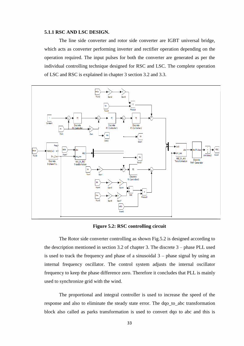
Figure 5.2: RSC controlling circuit
The Rotor side converter controlling as shown Fig.5.2 is designed according to
the description mentioned in section 3.2 of chapter 3. The discrete 3 – phase PLL used
is used to track the frequency and phase of a sinusoidal 3 – phase signal by using an
internal frequency oscillator. The control system adjusts the internal oscillator
frequency to keep the phase difference zero. Therefore it concludes that PLL is mainly
used to synchronize grid with the wind.
The proportional and integral controller is used to increase the speed of the
response and also to eliminate the steady state error. The dqo_to_abc transformation
block also called as parks transformation is used to convert dqo to abc and this is
Page 48
34
given as an input to discrete PWM generator. Pulses given to gate signal of RSC are
generated by using this block. The output of PWM acts as input to unit delay which is
used to hold and delay the input by the sample time specified.
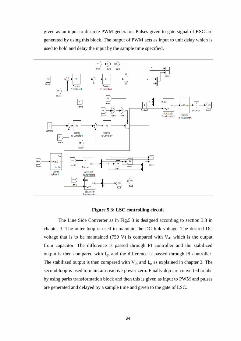
Figure 5.3: LSC controlling circuit
The Line Side Converter as in Fig.5.3 is designed according to section 3.3 in
chapter 3. The outer loop is used to maintain the DC link voltage. The desired DC
voltage that is to be maintained (750 V) is compared with Vdc which is the output
from capacitor. The difference is passed through PI controller and the stabilized
output is then compared with Iqs and the difference is passed through PI controller.
The stabilized output is then compared with Vds and Iqs as explained in chapter 3. The
second loop is used to maintain reactive power zero. Finally dqo are converted to abc
by using parks transformation block and then this is given as input to PWM and pulses
are generated and delayed by a sample time and given to the gate of LSC.
Page 49
35
5.1.2 BATTERY/FUEL CELL, SUPERCAPACITOR AND DUMP LOAD
CONTOL
The battery/fuel cell controlling is designed according to the section 4.5 of
chapter 4. The Super capacitor controlling is designed according to section 4.6 of
chapter 4 where the outer loop measures the DC link voltage VDC, which is compared
with the reference DC link voltage (Vdc)ref, and the error is compensated through a PI
controller to generate the reference current (Isc)ref. This current is then compared with
the actual super capacitor current isc, and the corresponding error is compensated
through second PI controller to generate the switching signal for DC – DC converter.
The main objective behind this control is to regulate the generator current which is
directly proportional to the load toque of the generator.
The Dump load is controller in designed in such a way that it operates when
the battery power, wind power and super capacitor power exceeds. This excess power
is absorbed by the dump load.
5.2 SIMULATION MODEL WITH FUEL CELL AND SUPER
CAPACITOR AS HYBRID ENERGY STORAGE
The simulation model with fuel cell and super capacitor is designed same as
that of simulation model 1. Since fuel cell are more efficient and has life cycle more
than batteries, so batteries are replaced by fuel cell. The function of fuel cell is same
as that of battery, so controlling is designed same as battery controlling. The
simulation model is shown in Fig.5.4.
Page 50
36
r
Figure 5.4: Simulation model with fuel cell and super capacitor
Page 51
37
5.3 PERFORMANCE OF THE HYBRID ENERGY STORAGE
SYSTEM BASED DFIG SYSTEM.
The torque and speed characteristics of DFIG are shown in Fig.5.5. The
negative torque represents the generating mode.
Figure 5.5: Torque and Speed of DFIG
5.3.1 BATTERY AND SUPER CAPACITOR RESULTS
The system response of the DFIG based RAPS system with battery and super
capacitor as hybrid storage system is shown in Fig.5.6 – Fig.5.9 whereas Fig.5.10 –
Fig.5.13 illustrates the power sharing between different system components.
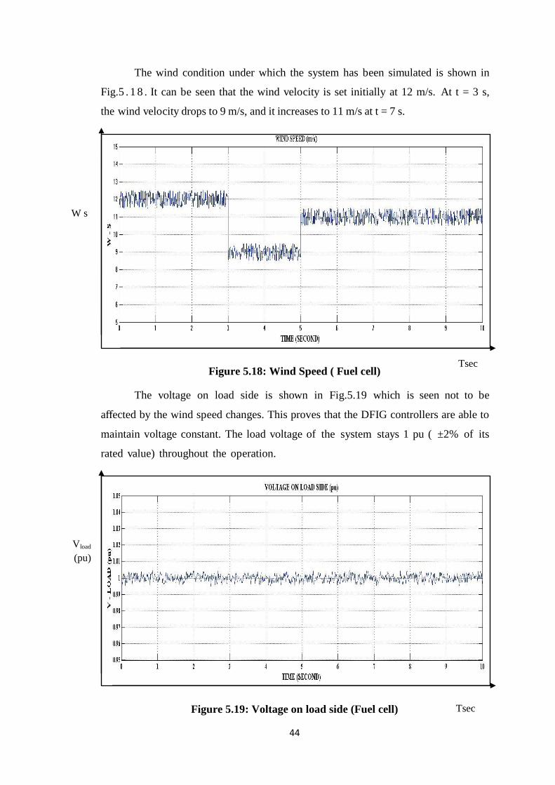
The wind condition under which the system has been simulated is shown in
Fig.5.6. It can be seen that the wind velocity is set initially at 12 m/s. At t = 3 s, the
wind velocity drops to 9 m/s, and it increases to 11 m/s at t = 7 s.
ωr
Te
Tsec
Page 52
38
Figure 5.6: Wind speed (Battery)
The voltage on load side is shown in Fig.5.7 which is seen not to be affected
by the wind speed or load changes. This proves that the DFIG controllers are able to
maintain voltage constant. The load voltage of the system stays 1 pu ( ±2% of its
rated value) throughout the operation.
Figure 5.7: Voltage on load side (Battery)
The operating frequency of the RAPS system is shown in Fig.5.8. The
operating frequency is closely regulated at its rated value of 50 Htz i.e., 1 pu and is
seen not to be influenced by the wind speed or load step changes. Furthermore, it can
W s
Vload
(pu)
Tsec
Tsec
Page 53
39
be seen that the frequency of the system is maintained within 0.2% of its rated
value.
Figure 5.8: Frequency on load side (Battery)
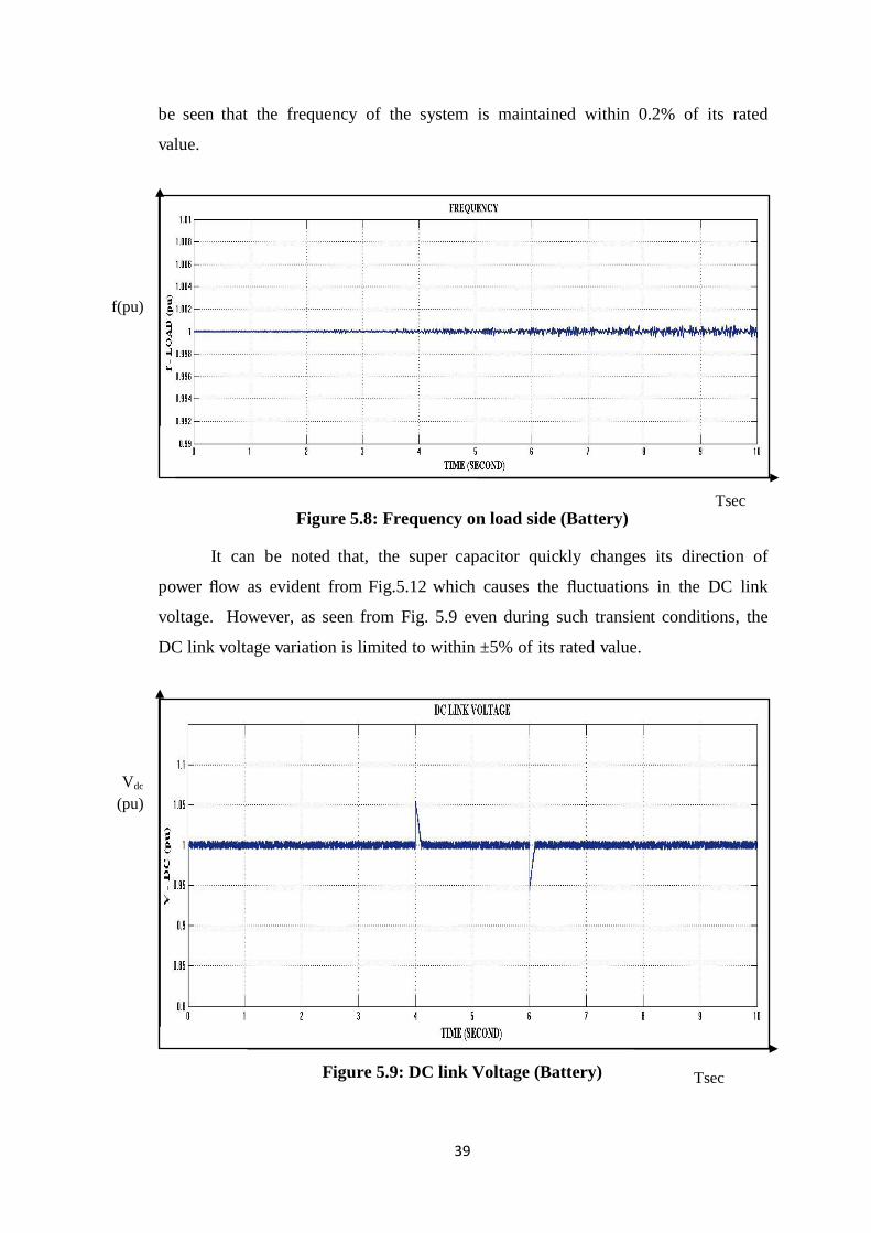
It can be noted that, the super capacitor quickly changes its direction of
power flow as evident from Fig.5.12 which causes the fluctuations in the DC link
voltage. However, as seen from Fig. 5.9 even during such transient conditions, the
DC link voltage variation is limited to within ±5% of its rated value.
Figure 5.9: DC link Voltage (Battery)
Tsec
Vdc
(pu)
Tsec
f(pu)
Page 54
40
Figure 5.10: Load Demand (Battery)
The DFIG power output is shown in Fig.5.11. As seen in Fig.5.10, initial
load demand is set at 0.425 pu and then it is increased to a value of 0.7 pu at t=4s
and the added additional load (i.e. 0.275 pu) is disconnected from the system at
t= 6 s.
As shown in Fig.5.11, the power output of the DFIG is seen to rise to a value
of 0.6 pu at t = 2 s and the corresponding load demand is at 0.425 pu. This leads to
an over – generation condition where the excess power is shared between the
battery storage system and super capacitor as evident from Fig.5.12.
Figure 5.11: Wind Power (Battery) Tsec
Pwind
(pu)
Tsec
Pload
(pu)
Page 55
41
It can be seen that the super capacitor responds to the fast varying power
variations while the battery absorbs the slow varying power variations of the
demand – generation mismatch. Also, the super capacitor responds quickly to load
step changes which occur at t = 4 s and t = 6 s avoiding high rates of DOD of the
battery storage system
Figure 5.12: Hybrid energy storage power
The battery storage system reaches its full capacity of 0.175 pu at t=2 s
leading to the operation of dump load which absorbs the additional power of 0.02
pu as evident from Fig.5.13.
Figure 5.13: Dump Load Power (Battery)
Tsec
Pd
(pu)
Tsec
Pb
(pu)
Pscp
(pu)
Page 56
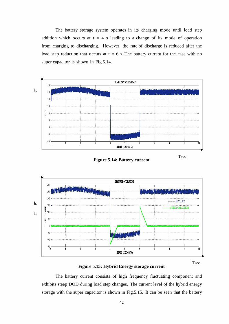
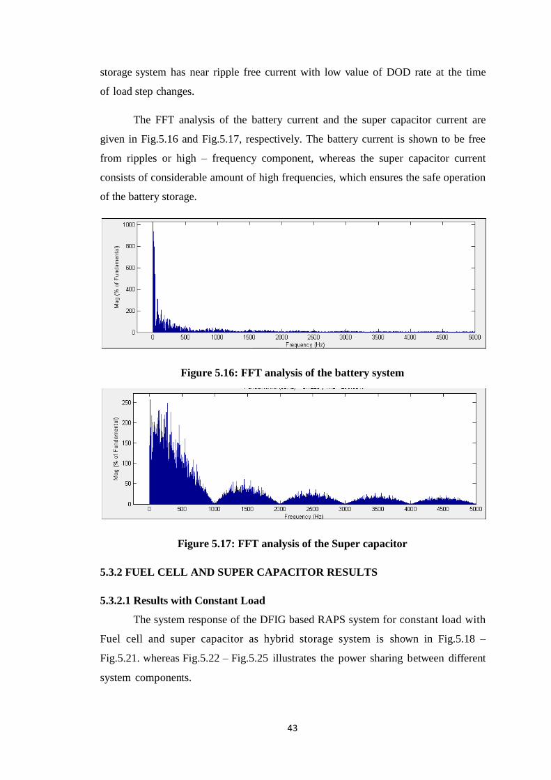
42
The battery storage system operates in its charging mode until load step
addition which occurs at t = 4 s leading to a change of its mode of operation
from charging to discharging. However, the rate of discharge is reduced after the
load step reduction that occurs at t = 6 s. The battery current for the case with no
super capacitor is shown in Fig.5.14.
Figure 5.14: Battery current
Figure 5.15: Hybrid Energy storage current
The battery current consists of high frequency fluctuating component and
exhibits steep DOD during load step changes. The current level of the hybrid energy
storage with the super capacitor is shown in Fig.5.15. It can be seen that the battery
Tsec
Ib
Is
Tsec
Ib
Page 57
43
storage system has near ripple free current with low value of DOD rate at the time
of load step changes.
The FFT analysis of the battery current and the super capacitor current are
given in Fig.5.16 and Fig.5.17, respectively. The battery current is shown to be free
from ripples or high – frequency component, whereas the super capacitor current
consists of considerable amount of high frequencies, which ensures the safe operation
of the battery storage.
Figure 5.16: FFT analysis of the battery system
Figure 5.17: FFT analysis of the Super capacitor
5.3.2 FUEL CELL AND SUPER CAPACITOR RESULTS
5.3.2.1 Results with Constant Load
The system response of the DFIG based RAPS system for constant load with
Fuel cell and super capacitor as hybrid storage system is shown in Fig.5.18 –
Fig.5.21. whereas Fig.5.22 – Fig.5.25 illustrates the power sharing between different
system components.
Page 58
44
The wind condition under which the system has been simulated is shown in
Fig.5 . 1 8 . It can be seen that the wind velocity is set initially at 12 m/s. At t = 3 s,
the wind velocity drops to 9 m/s, and it increases to 11 m/s at t = 7 s.
Figure 5.18: Wind Speed ( Fuel cell)
The voltage on load side is shown in Fig.5.19 which is seen not to be
affected by the wind speed changes. This proves that the DFIG controllers are able to
maintain voltage constant. The load voltage of the system stays 1 pu ( ±2% of its
rated value) throughout the operation.
Figure 5.19: Voltage on load side (Fuel cell)
W s
Tsec
Vload
(pu)
Tsec
Page 59
45
The operating frequency of the RAPS system is shown in Fig.5.20. The
operating frequency is closely regulated at its rated value of 50 Htz i.e., 1 pu and is
seen not to be influenced by the wind speed changes. Furthermore, it can be seen that
the frequency of the system is maintained within 0.2% of its rated value.
Figure 5.20: Frequency on load (Fuel cell)
Figure 5.21: DC link Voltage (Fuel cell)
The DC link voltage of the DFIG is depicted in Fig.5 .21 which is well
regulated rated value throughout the operation.
Tsec
Vdc
(pu)
Tsec
f (pu)
Page 60
46
Figure 5.22: Load Demand (Fuel cell)
The DFIG power output is shown in Fig.5.23,.As seen in Fig.5.22, load
demand is set at 0.425 pu throughout the operation.
Figure 5.23: Wind Power (Fuel cell)
As shown in Fig.5.23, the power output of the DFIG is seen to rise to a value
of 0.6 pu at t = 2 s and the corresponding load demand is at 0.425 pu. This leads to
an over – generation condition where the excess power is shared between the fuel
cell storage system and super capacitor as evident from Fig.5.24.
Tsec
Pwind
(pu)
Tsec
Pload
(pu)
Page 61
47
Figure 5.24: Hybrid energy storage power
The fuel cell storage system reaches its full capacity of 0.175 pu at t=2 s
leading to the operation of dump load which absorbs the additional power of 0.02
pu as evident from Fig.5.25.
Figure 5.25: Dump Load Power (Fuel cell)
The fuel cell storage system operates in its charging mode. The battery
current and super capacitor current is shown in Fig.5.26.
Tsec
Pd
(pu)
Tsec
Pfc
(pu)
Pscp
(pu)
Page 62
48
Figure 5.26: Hybrid Energy storage current
5.3.2.2 Results with Variable Load
The system response of the DFIG based RAPS system with fuel cell and
super capacitor as hybrid storage system is shown in Fig.5.27 – Fig.5.30, whereas
Fig.5.31 – Fig.5.34 illustrates the power sharing between different system
components.
The wind condition under which the system has been simulated is shown in
Fig.5 . 2 7 . It can be seen that the wind velocity is set initially at 12 m/s. At t = 3 s,
the wind velocity drops to 9 m/s, and it increases to 11 m/s at t = 7 s.
Figure 5.27: Wind Speed (Fuel cell)
Ifc
Is
W s
Tsec
Tsec
Page 63
49
The voltage on load side is shown in Fig.5.28 which is seen not to be
affected by the wind speed or load changes. This proves that the DFIG controllers are
able to maintain voltage constant. The load voltage of the system stays 1 pu ( ±2%
of its rated value) throughout the operation.
Figure 5.28: Voltage on Load Side (Fuel cell)
The operating frequency of the RAPS system is shown in Fig.5.29. The
operating frequency is closely regulated at its rated value of 50 Htz i.e., 1 pu and is
seen not to be influenced by the wind speed or load step changes. Furthermore, it can
be seen that the frequency of the system is maintained within 0.2% of its rated
value.
Figure 5.29: Frequency on Load Side (Fuel cell)
Tsec
Tsec
f (pu)
Vload
(pu)
Page 64
50
Figure 5.30: DC Link Voltage (Fuel cell)
The DC link voltage of the DFIG is depicted in Fig.5.30 which is well
regulated rated value throughout the operation except during load changes at 4 s and
6 s. However, the highest DC link voltage variations are seen to occur at t= 4 s and
t= 6 s which correspond to the load step changes as evident from Fig.5.31.
It can be noted that, the super capacitor quickly changes its direction of
power flow as evident from Fig.5.33 which causes the fluctuations in the DC link
voltage. However, even during such transient conditions, the DC link voltage
variation is limited to within ±5% of its rated value.
Tsec
Vdc
(pu)
Page 65
51
Figure 5.31: Load Demand (Fuel cell)
The DFIG power output is shown in Fig.5.32. As seen in Fig.5.31, initial
load demand is set at 0.425 pu and then it is increased to a value of 0.7 pu at t =
4 s and the added additional load (i.e. 0.275 pu) is disconnected from the system
at t= 6 s.
Figure 5.32: Wind Power (Fuel cell)
As shown in Fig.5.32, the power output of the DFIG is seen to rise to a value
of 0.6 pu at t = 2 s and the corresponding load demand is at 0.425 pu. This leads to
an over – generation condition where the excess power is shared between the fuel
cell storage system and super capacitor as evident from Fig.5.33.
Tsec
Pwind
(pu)
Tsec
Pload
(pu)
Page 66
52
It can be seen that the super capacitor responds to the fast varying power
variations while the fuel cell absorbs the slow varying power variations of the
demand – generation mismatch. Also, the super capacitor responds quickly to load
step changes which occur at t = 4 s and t = 6 s avoiding high rates of DOD of the fuel
cell storage system.
Figure 5.33: Hybrid Energy Storage Power
The fuel cell storage system reaches its full capacity of 0.175 pu at t=2 s
leading to the operation of dump load which absorbs the additional power of 0.02
pu as evident from Fig.5.34.
Figure 5.34: Dump Load Power ( Fuel cell) Tsec
Pd
(pu)
Tsec
Pfc
(pu)
Pscp
(pu)
Page 67
53
The fuel cell storage system operates in its charging mode until load step
addition which occurs at t = 4 s leading to a change of its mode of operation
from charging to discharging. However, the rate of discharge is reduced after the
load step reduction that occurs at t = 6 s. The battery current for the case with no
super capacitor is shown in Fig.5.35.
Figure 5.35: Fuel Cell Current
Figure 5.36: Hybrid Energy Storage Current
The Fuel cell current consists of high frequency fluctuating component and
exhibits steep DOD during load step changes. The current level of the hybrid energy
storage with the super capacitor is shown in Fig.5.36.
Tsec
Ifc
Is
Tsec
Ifc
Page 68
54
5.4 COMPARISON OF BATTERY AND FUEL CELL AS
STORAGE SYSTEMS.
Analysing the results of battery and fuel cell integrated with super capacitor it
is seen that both function equally to variations in wind speed and load, thus providing
same storage function.
As theoretically seen from [15], [16], [17] basic fuel cells run on pure
hydrogen so they are pollution free, giving off only electricity, water, and heat. The
potential for fuel cells to provide zero or near – zero emissions has forced to develop
this technology over the past 30 years, and is drawing increasing attention to the
technology today. The advantages of fuel cell over battery are:
There is no combustion in a fuel cell, so fuel is converted to electricity more
efficiently than any other electrical generating technology available today.
Unlike batteries that must be disposed of once their chemicals are used up,
fuel cell reactions do not degrade over time and can provide continuous
electricity.
Traditional power plants must be large in order to gain efficiency, but fuel
cells can achieve higher efficiencies at any scale, making them perfect for
small portable, residential, and transportation uses.
Because fuel cells are clean and efficient at any size, they can be located
almost anywhere, including dense urban areas where both air quality and
transmission congestion may be of concern. Fuel cells can offer an alternative
to building new power lines. Fuel cells can provide more reliable power
wherever electricity is needed, making the whole electric power grid more
robust and reliable.
Economically, fuel cells represent a prudent path to provide the country's
electric power because they can be installed quickly, are fuel flexible, and can
be put in place incrementally, mitigating the need for more costly and
sweeping changes.
5.5 CHAPTER SUMMARY
In this chapter simulation studies have been conducted of the proposed system.
Based on simulation results, following conclusion was drawn:
DFIG based RAPS system with hybrid energy storage system are able to
Page 69
55
regulate the voltage and frequency at PCC within limits.
DC link voltage was maintained at 750 V.
Battery and super capacitor responded efficiently depending on increase in
demand as observed form section 5.3.1.
Fuel cell and super capacitor responded efficiently depending on increase in
demand as observed form section 5.3.2.
At last, comparison of battery and fuel cell is done.
Page 70
56
CHAPTER 6
CONCLUSION AND FUTURE SCOPE
6.1 CONCLUSION
In this thesis, through simulation studies it can be concluded that hybrid
storage systems is capable in maintaining the voltage and frequency at the load end.
Also, it has been noted that the power sharing between the systems components was in
accordance with the proposed coordinated control methodology. The thesis has also
addressed the benefits of integrating a super capacitor to a battery / fuel cell storage
system and also explains the benefits of fuel cell when compared to battery in a wind
– based hybrid RAPS system.
When considering the operation of battery / fuel cell storage systems,
avoidance of heavy DOD rates and reduced ripple content in the battery / fuel cell
current is given importance. To solve above problem, a super capacitor was integrated
with the battery storage system to form the hybrid energy storage (i.e. battery / fuel
cell and super capacitor) and improving battery’s / fuel cell’s performance. It has also
been noted that the super capacitors integrated to the DFIG was able to handle the
transients caused by wind speed and load changes effectively. Charging and
discharging of battery makes it to run for only for few years and thus requires heavy
maintenance. To avoid this problem, batteries are replaced with fuel cells that can
provide continuous electricity for several years [18].
Thus concluding by stating that application of hybrid storage system to DFIG
based wind dominated RAPS systems is capable in maintaining the voltage and
frequency at the load end with proper power sharing between the devices.
6.2 FUTURE SCOPE
As extensions to the work presented in this thesis, following is a description of further
activities that can be undertaken in relation to standalone RAPS system:
Development of the control strategies for each component of RAPS systems
with a view to operate them under unbalanced load conditions.
Integration of other types of renewable energy systems (e.g. solar
photovoltaic) to wind based RAPS systems.
Page 71
57
Further development of the existing control strategies of the RAPS systems to
operate as a grid interactive micro – grid.
Page 72
58
REFERENCES
[1] http://www.mnre.gov.in.
[2] S. Bhattacharyya (ed.), Rural Electrification Through Decentralised Off-grid
Systems in Developing Countries, Green Energy and Technology, DOI:
10.1007/978-1-4471-4673-5_2, Springer-Verlag London 2013.
[3] Doubly fed induction generator system for wind turbine by BY S.
MÜLLER,M. DEICKE, & RIK W. DE DONCKER May/June 2011.
[4] N. Mendis, K. M. Muttaqi “Management of Low- and High-Frequency Power
Components in Demand-Generation Fluctuations of a DFIG-Based Wind-
Dominated RAPS System Using Hybrid Energy Storage,” IEEE Transactions
on Industry Applications, Vol. 50, No. 3, May/June 2014.
[5] John Fletcher and Jin Yang (2010). Introduction to the Doubly-Fed Induction
Generator for Wind Power Applications, Paths to Sustainable Energy, Dr Artie
Ng (Ed.), ISBN:978-953-307-401-6.
[6] Literature review paper on doubly fed induction generator wind turbine
technology Ajay Kushwaha1, Inderpreet Singh2 1,2EIED, Thapar University,
Patiala, Punjab, IndiaISSN: 2319-7463 Vol. 2 Issue 9, September-2013.
[7] Krisztina Leban. Doubly Fed Induction Generator Fault Simulations. PhD
thesis, Institute of Energy Technology, Aalborg University, Alborg, Denmark,
2009.
[8] R. Pena, J. C. Clare, and G. M. Asher. Doubly fed induction generator using
back – to – back pwm converters and its application to variable – speed wind –
energy generation. IEE Proceedings - Electric Power Applications, 143(3):231
– 241,May 1996.
[9] D. Santos-Martin, S. Arnaltes, and J. L. R. Amenedo. Reactive power
capability of doubly fed asynchronous generators. Journal of Electric Power
Systems Research, 78(11):1837 – 1840, Nov. 2008.
[10] P. F. Ribeiro, B. K. Johnson, M. L. Crow, A. Arsoy, and Y. Liu, “Energy
storage systems for advanced power applications,” Proc. IEEE, vol. 89, no. 12,
pp. 1744–1756, Dec. 2001.
[11] M.Beaudin,H.Zareipour,A.Schellenberglabe,andW.Rosehart,“Energy storage
for mitigating the variability of renewable electricity sources: An updated
review,” Energy Sustainable Develop., vol. 14, no. 4, pp. 302– 314, Dec.
2010.
Page 73
59
[12] Kuldeep Sahay; Bharti Dwivedi; “Design and Analysis of Supercapacitors
Energy Storage System for Energy Stabilization of Distribution Network” in
Electrical Power Quality and Utilisation Journal Vol.XV, No.1, 2009.
[13] T. Patrick and Moseley, “Energy storage in remote area power supply
(RAPS)systems,”J.PowerSources,vol.155,no.1,pp.83–87,Apr.2006.
[14] W. Li, G. Joos, and J. Belanger, “Real-time simulation of a wind turbine
generator coupled with a battery supercapacitor energy storage system,” IEEE
Trans. Ind. Electron., vol. 57, no. 4, pp. 1137–1145, Apr. 2010.
[15] P. Thounthong, S. Rael, and B. Davat, “Control strategy of fuel cell and
supercapacitors association for a distributed generation system,” IEEE Trans.
Ind. Electron., vol. 54, no. 6, pp. 3225–3233, Dec. 2007.
[16] R. K. Shah “Introduction to fuel cells”
[17] Paul Kaeser, Kantonsschule Baden “Batteries” May 2010
[18] http://www.altenergy.org/renewables/fuel_cells.
Page 74
60
APPENDIX
A.1 PARAMETERS ASSOCIATED WITH DFIG BASED RAPS
SYSTEM.
Table A.1: Parameters
S.No. PARAMETERS RATINGS
1. Rated power output (PDFIG) 750 kW
2. Stator resistence (Rs) 0.00706 pu
3. Stator leakage inductance (Lls) 0.171 pu
4. Rotor resistance (Rr) 0.005 pu
5. Rotor leakage inductance (Llr) 0.156 pu
6. Magnetising inductance (Lm) 2.2 pu
7. Inertia constant (H) 2.04 S
8. Number of pole pairs (P) 3
9. Filter inductance at LSC (Lf) 0.3 pu
10. Filter resistance at LSC (Rf) 0.003 pu
11. DC capacitance 5000e-6
12. DC bus voltage (Vdc) 750 V
13. Stator voltage ( Vs) 400 V
14. Operating frequency (fs) 50 Hz
15. Rating of battery storage system (Pb) 420 kWh
16. Capacitance of Super capacitor (C) 20 F
17. Rating of Fuel cell 50kW
18. Allowable SOC of the battery system (SOC) 40 % - 80 %
19. Rated dump load power ((Pd)max) 20 kW