WT-934 (EX) EXTRACTED VERSION OPERATION CASTLE 410201 Summary Report of the Commander, Task Unit 13 Military Effects, Programs 1-9 Pacific Proving Grounds March – May 1954 Headquarters Field Command Armed Forces Special Weapons Project Sandia Base, Albuquerque, New Mexico January 30, 1959 NOTICE Thisisan extractof WT-934, OperationCASTLE, Summarv ReDort of the Commander, Task Unit 13, ,. which remains classified DATA as of thisdate. Extractversionprepared 15 Director SECRET/RESTRICTED for: DEFENSE NUCLEAR AGENCY Washington, D.C. 20305 May 1981 Approved for public release; distribution unlimited.
Transcript
WT-934 (EX)EXTRACTED VERSION
OPERATION CASTLE410201
Summary Report of the Commander,Task Unit 13Military Effects, Programs 1-9
Pacific Proving GroundsMarch – May 1954
Headquarters Field CommandArmed Forces Special Weapons ProjectSandia Base, Albuquerque, New Mexico
January 30, 1959
NOTICE
This isan extractof WT-934, OperationCASTLE,Summarv ReDort of the Commander, Task Unit 13,,.which remains classifiedDATA as of thisdate.
Extractversionprepared
15
Director
SECRET/RESTRICTED
for:
DEFENSE NUCLEAR AGENCY
Washington, D.C. 20305
May 1981
Approved for public release;distribution unlimited.
Office of the Deputy Chief of Staff,Weapons Effects Tests
——1. COUTROLLIWG OfFICE 14AuE A~D AOORESS
Headquarters, Field CommandArmed Forces Special Weapons ProjectSandia Base, Albuquerque, New Mexico
._——— —14.}40?41To RI14G AGENCY NAME h AODRESS (If d: ff. r.nl l,om Con fro fI/n# Of f;..)
._— ——= OISTRIBUTIOM s7ATEMEMT f~ff~f~ R*pOro
READ INSTRUCTIONS – —BEFORE COk\PLETING FOR~.— _i. FItCIPICMT”S CATALOc NUMBER
—S. TYPE OF RCPORT A PERIOOCOVERCO
t. PERJORUIMG ORG. RiIPORT NUMBER
WT-934 (EX)●. C9MTRACT OR CRAHT NUMmc~.J
10. PROGRAM ELEuEMT.PROJCCT~T ASKAREA t WORK UNIT MUKSERS
12. REPORT OATE
January 30, 1959II,NUMBEROF PAGES
IS. SECURITY CLASS. (of fhl, ,.porfJ
SOECI_ASSIFICATIOH/DOWH GRAOING
Approved for public release; unlimited distribution”
—.la. SUPPLEKL14TAR$ NOTES
This report has had the classified information removed and has been republished inunclassified form for public release. This work was performed by Kaman Tempo undercontract DNAO01-79-C-0455 with the close cooperation of the ClassificationManagement Division of the Defense Nuclear Agency.
l!. KEY wORDS (Cc. nf; nu - o“ ,., .,,. id. ifne-CC.t.7 md Idsnflfy by ~rock ~u~~*r~
—. _—— —— .—— _—0. AC ST RACT (cmll”i,. .- ,. ..!,.
—.;4. If n.. . . ..ry ●“d Jd. nf, fy by t!ock r.”-~-~)
Operation Castle consisted of six nuclear detonations at the Eniwetok Proving Groundduring the period 1 March to 14 May 1954. Two were surface or near-surface land shots:one on a natural island and the other on a man-madeisland at the end of a causeway.The other four shots were fired on barges: two anchored in reef craters from previousshots and the other two anchored in the lagoon proper.
The Department of Defense (DOD) military-effect program consisted of 37 projectsdivided among six planned programs and one program (biomedical) added in the field; inaddition, one Los Alamos Scientific
\$&%%!!st.LASL) program (thermal radiation) was
concerned with an area of mllltary-e—.— _—. —.—.-c mnM ----
In general, the principal objectives of the military-effect programswere realized. The numerous changes in shot schedules together with therepeated delays due to unfavorable weather forced many revisions and last-minute improvisations in many projects’ plans. For some-notably thoseconcerned with documenting fallout-much information was thereby lost; forother projects, such as those involving effects on aircraft, the repeateddelays allowed completion of necessary maintenance between shots and resultedin almost 100-percent participation.
Despite uncertain yields and delays, the blast program obtained aconsiderable amount of worthwhile data and achieved its objectives. Waveforms from the surface gages were nonideal in shape for both overpressureand dynamic pressure and demonstrated that water is not an ideal surface-it sometimes had been presumed to be ideal. Precursors as such were notdetected. The uncertainly of the free-air data did not permit any definiteconclusions regarding the effects of a nonhomogeneous atmosphere on the blastwave. Data from a megaton burst over a shallow water layer indicated thatexcept for theclos.+in region, underwater pressures are of comparablemagnitude to the direct air-blast overpressures at the same range. Incontrast to results from Operation Ivy, studies at Castle indicated that surfacewater waves do emanate from the central region of the detonation and thatrefraction and reflection against reefs and shores can significantly affecttheir destructive capability.
In the nuclear-radiation and fallout program, the unexpectedly high yieldof Shot 1 caused destruction of much of the spare equipment on Site Tare,curtailing instrumentation on future shots; however, the important militarysignificance of fallout over large areas beyond the blast- and thermal-damageenvelopes was demonstrated dramatically. The realization that activitydissolved in sea water could be a measure of the fallout intensity providedthe impetus for the water and aerial surveys that provided valuable dataafter Shots 5 and 6.
In the blast-effect program, the instrumented, rigid concrete cubiclewas exposed to a blast intensity from Shot 3 of only about a tenth of thatpredicted. Although the specific objective of that particular project wasnot accomplished, an evaluation of the blast-loading data therefrom made bySandia Corporation showed that two loading-prediction procedures werereasonably good. The documentation of air-blast effects on miscellaneousstructures was an unplanned project of opportunity-one initiated because ofthe damaging, unexpectedly high yield of Shot 1.
Crater size data was obtained as planned, increasing considerably thereliability in predictions of craters produced by megaton weapons.
Despite unexpected deviations from predicted yields for Shots 1 and 3,breakage data and other results on damage to natural tree stands were obtained.
The underwater minefield-121 mines of various types set 180 feet deepand exposed to a 7.0 Mt surface detonation-gave data on the extent ofneutralization of these mines by the detonation.
Extensive data was obtained in the biomedical study of the individualsacciently exposed to significant amounts of fallout radiation. Total gammadosages up to 182 r were received and produced the physical effects expected.
The actual yield of Shot 1 was approximately 25 percent greater than thepositioning yield used for the effects studies on aircraft in flight. Anoverpressure of 0.81 psi was recorded on the B-36; damage to the B-36necessitated replacement of the bomb-bay doors, aft lower Plexiglas blisters,and the radar-antenna radome.
The specific techniques used during Castle to predict thermal inputs andresponses were inadequate for accurate, close positioning of the aircraft.The procedures utilized to predict blast effects at overpressures less than1.0 psi were satisfactory. In general, good correlation was obtained betweenmeasured and predicted values.
Results of contamination-decontamination studies with the two remote-controlled ships (YAG-39 and YAG-40) indicated that washdown effectivenessbased upon the reduction of accumulated gamma dose averaged approximately90 percent. Measured shielding factors on the YAG-40 were between 0.1 and0.2 between the second and upper deck and varied from 0.03 and 0.05 betweenthe upper deck and the hold.
Results of the Strategic Air Command’s evaluation of interim indirect-bomb-damage assessment (IBDA) procedures indicated that current equipment andoperating techniques were adequate. Scope photographs showed the typicalhorseshoe-shaped configuration during the early moments following time zero.The location of ground zero was established within an accuracy of 600 to1,100 feet by determining the center of curvature for the horseshoeconfiguration. Computation of yields proved inaccurate.
In the studies of the effects on the ionosphere, it was observed at theParry Island ionosphere recorder that severe absorption occurred for severalhours following all megaton shots. It appears that the duration of thedisturbances was related in some manner to the yield of the device and wasabout inversely proportional to the distance.
In the investigation of the problem of long-range detection of nuclearexplosions, azimuthal errors with ~3 degrees were experienced in locatingthe source by utilizing the electromagnetic effects. Reception and identifica-tion of detonation pulses when the time of detonation was known to a milli-second were relatively easy; however, to do the same thing on a 24-hour basiswith the detonation time unknown would have been much more difficult. It wasfound that more information is needed on techniques of discrimination. Thereappeared to be an approximate relationship between yield and the frequency atwhich peak energy occurs.
The photography program obtained data that was more complete and accuratethan any obtained on previous operations. Good measurements of cloud heightand diameter over a 10-minute interval were compiled for the five shotsphotographed.
FOREWORD
This report has had classified material removed in order tomake the information available on an unclassified, openpublication basis, to any interested parties. This effort todeclassify this report has been accomplished specifically tosupport the Department of Defense Nuclear Test Personnel Review(NTPR) Program. The objective is to facilitate studies of thelow levels of radiation received by some individuals during theatmospheric nuclear test program by making as much informationas possible available to all interested parties.
The material which has been deleted is all currentlyclassified as Restricted Data or Formerly Restricted Data underthe provision of the Atomic Energy Act of 1954, (as amended) oris National Security Information.
This report has been reproduced directly from availablecopies of the original material. The locations from whichmaterial has been deleted is generally obvious by the spacingsand “holes” in the text. Thus the context of the materialdeleted is identified to assist the reader in the determinationof whether the deleted information is germane to his study.
It is the belief of the individuals who have participatedin preparing this report by deleting the classified materialand of the Defense Nuclear Agency that the report accuratelyportrays the contents of the original and that the deletedmaterial is of little or no significance to studies into theamounts or types of radiation received by any individualsduring the atmospheric nuclear test program.
ABSTRACT
Operation Castle cxmeistod of S!X mwiear detonations at the Exdewtok Proving Groundduring the period 1 Maroh to 14 ~ 19S4. Two were surface or near-surface land shots:one on a natural isl~ emd t&J other on a man-made island at the end of a causeway. Theother four shots were fired on barges: two anchored in reef craters from previous shotsand the other two anchored in the 1400n proper.
The Department of Defense @D) rnllitary-effect program consisted of 37 projectsdivided among six planned programs end one program (biomedical) added in the field; inaddition, one Los Alarnos Scientific Laboratory (LASL) program (thermai radiation) wasconcerned with an area of military-effect interest.
Program 1, the blast program, was designed to document information on shock pa-rameters in the propagation of the blast wave incident on and through the media of air,ground, and water for devices with yields in the megaton range.
Program 2, the nuclear-radiation program, had two primary objectives: documenta-tion of the initial neutron and gamma radiation, and documentation of fallout from land-surface acd water-surface bursts; both efforts were devoted to rniltimegaton-yielddevices.
Program 3, the blast-effect program, concentrated on (1) obtaining loading data forprcrfict ing structural response and damage from multimegaton air blast, (2) gatheringciat~ on t!!e dimensions of apparent craters formed by multimegaton-yield shots for usein crater-size prediction, (3) studying blast damage to forested areas, and (4) deter-mining the effects on a planted sea mfnefield from a water-surface detonation.
Program 4, the biomedical prcqpm, was organized immediately after the accidentalexposure of human beings on Rongelap, Ailinglnae, Rongerik, and Uterik to the falloutfrom Shot 1, in order to (1) eveluate the severity of the radiation injury to those exposed,(2) provide all neaessary medical care, arxi (3) conduct a scientific study of radiationinjuries to human beings.
Program 6 was a composite program covering tests of service equipment and tecb-nfques. The ultimate objective of the aircraft-participation projects was the establish-ment of operational and design criteria concerning nuclear-weapon delivery aircraft,both current and future; measurements of overpressures, gust loading, and thermaleffects were made on aircraft in flight. In order ta evaluate washdown countermeasures,two converted, remote-controlled Liberty ships were placed in multimegaton falloutpatterns. In addition to simulating tactical conditions aboard a ship during and afterfallout, these vessels were equippd to collect fallout on their weather surfaces forcontamination-decontamination studies and housed instrumentation for studies of falloutmaterial. Also, their weather surfaces served as a radiating surface for shieldingstudies. Lastly, one pro ject studied effects on the ionosphere.
Program 7, the long-range-detection program, was concerned with the problem ofdetecting and locating the detonations and documenting them to the maximum extent pos-sible.
Program 9 performed the photographic documentation function. In addition, a photo-
5
grammetry project determined nuclear-cloud parameters as a function of time and at-tempted to establish scaling relationships for yield.
program 18, the thermal-radiation program, was administered by LASL. As a res~t,the DOD had no projects devoted exclusively to thermal-radiation measurements. Instead,to obtain thermal data of interest and avoid duplication of the Los Alamos efforts, theDOD provided funds for enlarging slightly the scope of Program 18.
In general, the principal objectives of the military-effect programs were reahzed.The numerous changes in shot schedules together with the repeated delc.ys due to un-favorable weather forced many revisions and last-minute improvisations in many projects’plans. For some —notably those concerned with documenting fallout — much information-was thereby lost; for other projects, such as those involving effects on aircraft, the re-peated delays allowed completion of necessary maintenance between shots md res[dtedin almost 100-percent participation.
Despite uncertain yields and delays, the blast program obtained a considerable amountof worthwhile data and achieved its objectives. Wave forms from the surface gages werenonideal in shape for both overpressure and dynamic pressure and demonstrated thatwater is not an ideal surface —it sometimes had been presumed to be ideal. Precursorsas such were not detected. The uncertainty of the free-air data did not permit any defi-nite conclusions regarding the effects of a nonhomogeneous atmosphere on the blast wave.Data from a megaton burst over a shallow water layer hdlcated that except for the close-in region, underwater pressures are of comparable magnitude to the direct sir-blxtoverpressurea at the same range. In contrast to resuh from Operation Ivy, studies atCastle indicated that surface water waves do emanate from the central region of the det-onation and that refraction and reflection against reefs and shores can significantly affecttheir destructive capability.
In the nuclear-radiation and fallout program, the unexpectedly high yield of Shot 1caused destruction of much of the spare equipment on Site Tare, curtailing instrumenta-tion on future shots; however, the important military significance of fallout over largeareas beyond the blast- and thermal-damage envelopes was demonstrated dramatically.The realization that activity dissolved in sea water could be a measure of the fallout in-tensi~ provided the impetus for the water and aerial surveys that provided valuable dataafter Shots 5 and 6.
In the blast-effect program, the instrumented, rigid concrete cubicle was exposed toa blast intensi~ from Shot 3 of only about a tenth of thatpredicted. Although the specificobjective of that particular project was not accomplished, an evaluation of the blast-loading data therefrom made by Sandia Corporation showed that two loading-predictionprocedures were reasonably good. The docuxrumtatton of air-blast effects on miscellane-ous structures was an unplanned project of opportunib —one initiat=l because of thedamaging, unexpectedly htgh yield of &ot 1.
Crater size data was obtsdmd as planned, imreaslng considerably the reliability inpredictions of craters produoed * megaton wempm6.
Despite unexpected deviations tiom pradioted ylekla for lbte 1 ad 3, breakage dataad other results on damage to natural tree atadm ware oMainad.
The underwater minefleld— Ml mines of various types set 180 feet deep and exposedb a 7 .O-Mt surface detonatlon— gave data m k exteat of aeutraifaation of these minesby the detonation.
Extensive data was obtained in t&e biotid study of the fmilvlduals accidently ex-posed to significant amounts of fallout redlation. TotaA garnm8 dosages up to 182 r werereceived and produoed the physical effeots expected.
The actual yield d Shot 1 was approximately 25 peroemt greater than the positioning
yield used for the effects etudes oa aircraft in flight. An overpreasure of 0.81 psi wasrecorded on the B-36; damage to the B-36 necessitated replacement of the bomb-baydoors, aft lower Plexiglas blisters, and the radar-antenna radome.
The specific techniques used during Castle to predict thermal inputs and responseswere inadequate for accurats, close positioning of the aircraft. The prmedures utilizedto predict blast effeots at overpresmres less than 1.0 pai were satisfactory. In general,good correlation was obtained b-n measured and predicted values.
Results of contamination~ nation studies with the two remote-controlled ships(YAG-39 and YAG-40) idicated that washdown effectiveness based upon the reduction ofaccumulated gamma dose avers@ approximately 90 pa rcent. Measured sMelding factorson the YAG-40 were between O.1 ad O.2 beween the second and upper deck ad variedfrom 0.03 and 0.05 between the upper ckk and the hold.
Results of the StrategSc Alr Command’s evaluation of interim indirect-bomb-damageassessment (IBDA) procedures indicated that current equipment and operating techniqueswere adequate. Scope photographs showed the typical horesehoe-shaped configurationduring the early moments follow~ time zero. The location of ground zero was estab-lished wi*fin an aoouracy of 600 to 1,100 feet by determining the center of curvature forthe horseshoe configuration. Computation of yields proved inaccurate.
In the studies of the effects on the ionosphere, it was observed at the Par~ Islandionosphere recorder that severe absorption occurred for several hours following allmegaton shots. It appears that the duration of the disturbances was related in somemanner to the yield of the device ad was about inversely proportional to the distance.
Ix the investigation of the problem of long-range detection of nuclear explosions,~dimmhal errors within + 3 degrees were experienced in locating the source by utilizingthe electromagnetic effects. Reception and identification of detonation pulses when thetime of detonation was known to a millisecond were relatively easy; however, to do thesame thing on a 24-hour basis with the detonation time unknown would have been muchmore difficult. !t was found that xmre information is needed on techniques of discrimi-nation. There appeared to be an approximate relationship between yield and the fre-quency at which peak energy occurs.
The photography program obtained data that was more complete and accurate thanany obtained on previous operations. Good measurements of cloud height and diameterover a 10-minute interval were compiled for the five shots photographed.
7-8
PREFACE
This report ia the final Bumma ry of the MllMry-effect t8st program conducted duringOperation Ca@Je at the Eniwetok, then called the “Pacific, ” Proving C3roand in thespring of 1954. It has been prepared by the Director, Test Division, mid his etaffof the C)fYice of the Deputy Chief of Staff for Weapons Efhcts Testsi, Field Command,AFSWP. Although a few military-effect Project reports were not yet published when thissumm~ was written, all had been suhmltted in draft form and were available forreference i)2 preparing this sumnmy report.
TM report (WT-934j supersedes the preliminmy summary (WR-934), whtch wasprepared a month after the last shot was fired on Operation Castle. That preliminarysummary had been prepared by the Commander, Task Unit 13, and his staff, with theassistance of Dr. H. Scoville, J-r., then Technical Director, AFSWP.
Contributions to this final summary report were de by tie fo~owing:K. II. Coletnmn, Co!, USAF, Directnr, Test DivisionA. H. Hig,gs, CDR, USN, Deputy Director, Test DivisionL. I+. Killiu,l, Maj, USAF, Technical Assistant, Test DivisionH. T. Bing!mm, hlaj, USAF, Directm, Program 1J. R. Kelso, Blast Branch, Headquarters, AFSWPG. C. Facer, CDR, USN, Director, Program 2J. A. Chiment, Maj, USA, Assistant Director, Program 2V. A. J. Var Lint, Pfc, USA, Staff Assistant, Program 2J. F. Clarke, LCDR, USN, Director, Program 3C. W. Em&es, Lt Col, USA, Director, Program 4F. E. O’Brien, Lt Ccl, USAF, Director, Program 5S. G. Shilling, CRD, USN, Assistant Dmxtor, Program 5H. Black, Lt Col, USA, Director, Program 6W. C. Linton, Maj, USA, Director, Programs 7 and 8
J. G. James, Lt Co!, USAF, Director, Program 9W. M. Sheahan, Id Col, USA, Assistant Director, Program 9W S. Isengard, Maj, USAF, Assistant Director, Program 9G. p. Forsyth, Maj, USAF, Fiscal
P. W. Williams, C WO, USA, Administrative Officer, Test DivisionW. J. Miller, Chief, Reports BranchE. R. Jennings, Assistant Chief, Reports BranchD. A. McNeill, ENS, USN, Analysis Officer, Reports Branch.The preliminary summary report has been used as a point of departure in preparing
this final summary; thus, much of the material herein is based directly on the prelimi-nary version. The following had made significant contributions to that preliminaryreport:
H. K. Gilbert, Coi, USAF, (DWET), Commander, Task Unit 13
*At the time of Operation Castle, this office was designated as the Directmate of WeaponsEffects Tests (DWET).
9
N. E. Kingsley, Capt, USN, (AFSWP), DePUtY Commander, Task Unit 13, andDirector, Program 3
Dr. H. Scoville, Jr., Technical Director, AF’SWPW. L. Carlson, CDR, USN, @wET), Director, Program 1E. A. Marten, Lt Col, USA, (DWET), Director, Program 2E. P. Cronkite, CDR, USN, @WIRI), Direcmr, program 4
D. I. Prickett, Lt Col, USAF, (DWET), ‘Director, Programs 5 and 6P. R. Wignall, Col, USAF, (AFOAT-1), Director, Program 7J. G. James, Lt Coi, USAF, (DWET), Director, Program 9
This final report is organized to present (1) a general summary of the background ofmilitary-effect participation on Castle in the first chapter, (2) a general discussion ofthe findings of each test program in subsequent chapters, and (3) a brief abstract of eachproject and bibliographical information on each project report in the Appendix.
Su.mmary of Shot Data mxtEEvironmentaI Corxlftions --------------- 17FundingarAd Coats, Mili~-Effect Test Program ----------------- 20Scaling Factors --------- ------------------------------- 24Comparison of Measured and Calculated Values of Dynamic
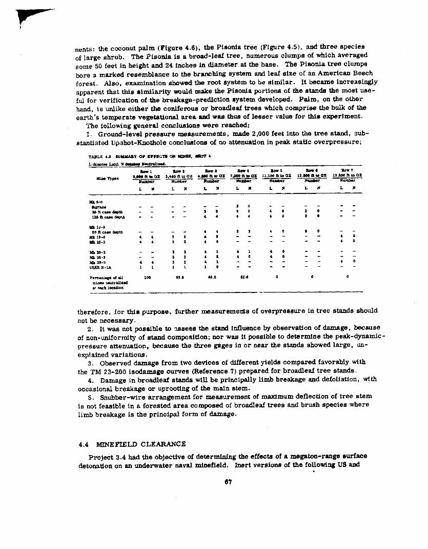
Pressure - - - - - ---- - - - -- ----- - -- - -- - - -- -- -- -- - - -- - - 25Acceleration Data - - - - . - --- - - -- --- - -- - - - - - - - - ---- -s -- -- -- 33Summa.iy ~fPressure-’I’ime Data, Shot S----------------------- 38Are.ascf Average Residual (3amma Actfvity --------------------- 46Capture- TG-Fission Ratio ----- ----- ----- ----- ----- ----- --- 53C r Mer %rvey Data ------ ------ ------ ------ ------ ------ - 65SulnInaryof Effeota on Mines, Shot 4 ------ ------ ----_- ------ - 67Desired and AcW Positions at Time Zero and Tfme
(r/hr at H + 1 hour) ------- ------- -------- ------- -----
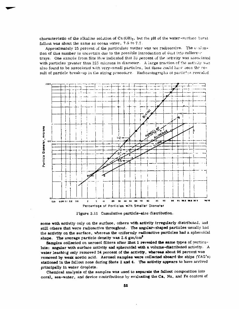
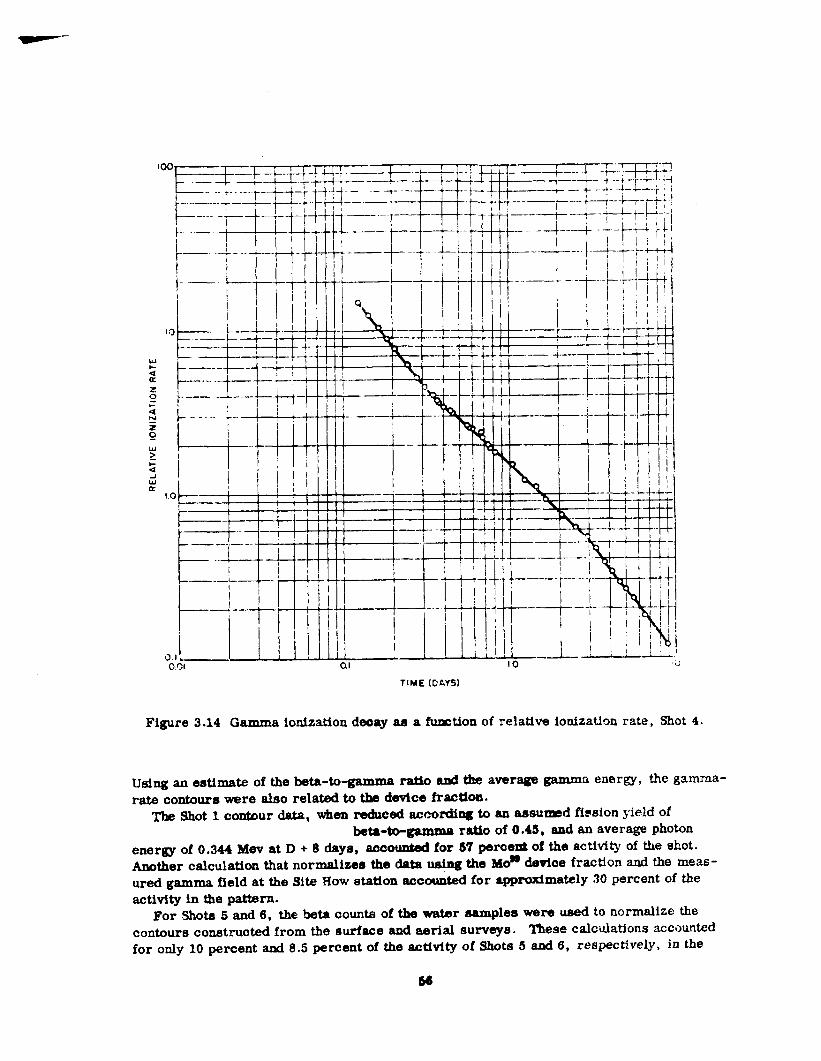
3.6 Residual gamma rate versus time, Shot I ---------------- -------3.7 Close-in gamma fallout pattern, Shot 3, (r/hr at H + 1 hour) ----------3.8 Close-in gamma fallout pattern, Shot4, (r,’hrat lf+lhour )-------- --3.9 Exposure-rate contours, Shot 5, (r/hr at H + 1 hour) ----------------3.10 Exposure-rate contours, Shot 6, (r/’hr at H + 1 hour) --------------3.11 Cumulative particle-size distribution ----------------- --------3.12 Gross beta decay of fallout samples from Shots 1, 2, 3, and 4 ---------3.13 Gross gamma decay of fallout s?.mples from Shots 1, 2, 3, and 4 ------3.14 Gamma ionization decay as a function of relative ionization
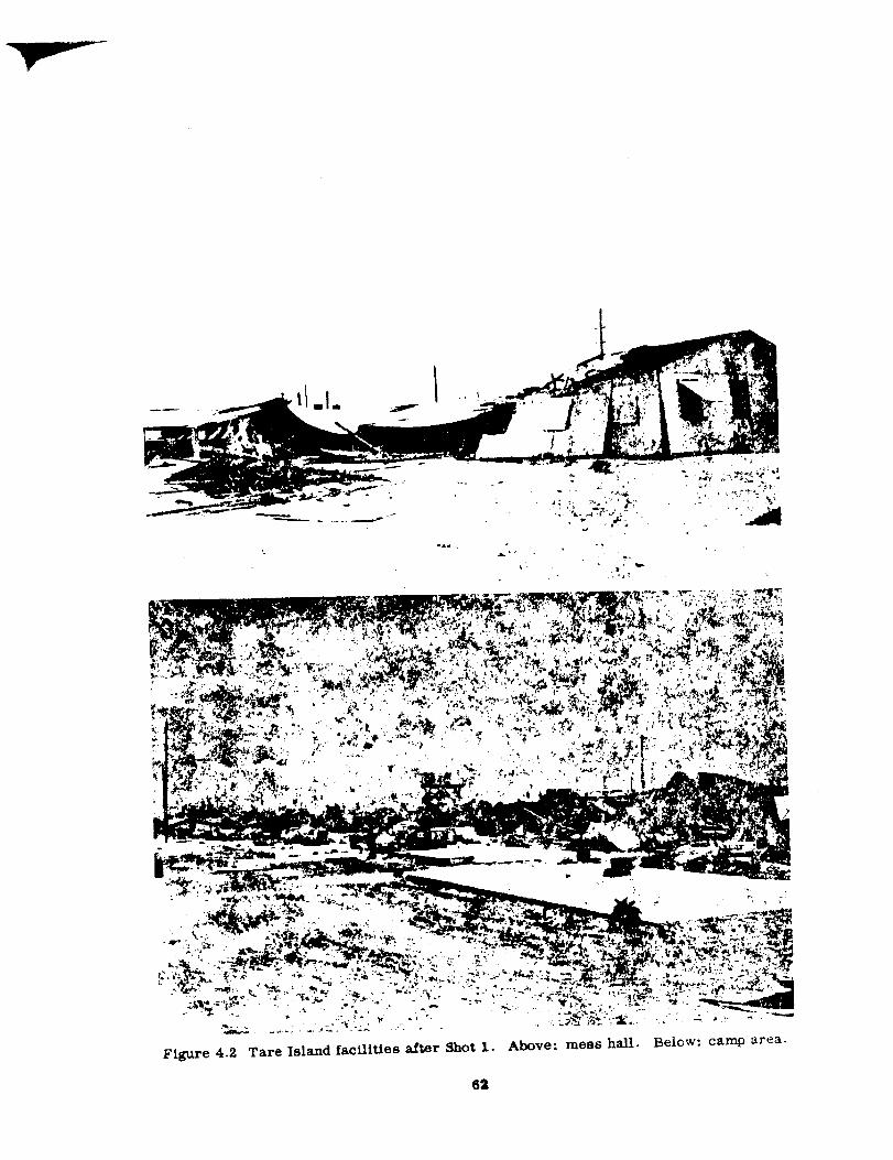
3.15 Calculated beta decay ---------------------- --------------4.1 Test cubicle, Project 3-1----------------------------------4.2 Tare Island facilities after Shot 1 ----------------------------4.3 Close-in instrument shelters after Shot 1 -----------------------4.4 A.erial tiewofcrater formedby Shotl ------------------------4.5 Sample Pison.ia Plct D, Uncle Island, looking toward
ground zero ------ ------- ------ -------- ---- ----- ----
4.6 Sample Palm PIot B, Uncle IsIand ----------------------------6.1 The YAG-39 with the washdown system operating -----------------6.2 Ship’s course, Shot 5 ------ ------ ------ ------- ------ -------
6.3 Apparent absorption coefficient g as a function of time --------------6.4 Radiation contours from original beta survey on the YAG-40
after Shot5, 8May 1954 ------------------------------6.5 Radiation contours from original gamma survey on the
YAG-40after Shot5, 8May 1954 ------------------------6.6 Evaluation of experimental decontamination procedures,
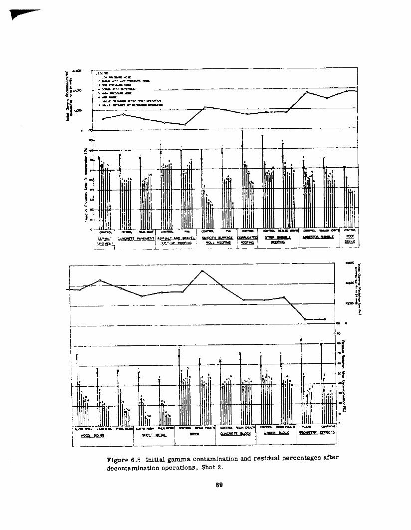
YAG-40, shot 2 ------------------------------------6.7 Percent of original contaminant remaining versus manpower ----------6.8 Initial gamma contamination and residual percentages after
decontamination operations, Shot 2 -----------------------6.9 TMrdpicture after H-hour at about H+4 seconds -----------------6.10 Progress of shock front at H + 22 seconds ------ ------ ------ ---
J?363942,Cz J4545
464749495051525455
56575962
6364
68697981
83
85
86
8788
999090
14
Choptef I
IN?’ROWCVON
The Armed Forces Special Weapons Project (AFSWP ) was inforxred in April 1952 of plansof the U. S. Atomic Energy Commission (AEC) to conduct a developmental test of h.fgh-yield weapons at the Eniwetok Proving Ground (EPGJ in the fall of 1953 (subsequentlydeferred to spring of 1954) under the code name Castle (Reference 1). Inasmuch ssOperation Ivy — the. first test involving high-yield weapons —was then Ming preparedfor conduct in the fail of 1952, no immediate steps were taken by AFSWP to plan forOperation Castle. In August 1952, AFSWP requested the military services to submitprcject proposa!s for 2. military-effect test program for Castle (Reference 2). On thebasis of the proposals submitted, AFSWP presented to the Committee on Atomic Energyof the Research arid Development Board on 17 Qecember 1952 an outline for a mtlitary -efiect test program Af@ r appropriate discussion (including additional hearings on thelong-range -detection program, Program 7, and the shipboard -cauntermeaaures project,Pr,)jec: 6.4), the Research and Development 130ard aipproved the program (Reference 3)anti iiutlatcd rc!case to AFSWP of research ad development funds (see Section 1.3).
1. ~ hfl~IT~~.E ~ FE~T ~~~~M
Tne military-effect program, as approved by the Research and Development Board,was of necessi~ couched in very general terms. Only preliminary data was as yet avail-~ble from Operation Ivy, and a firm shot schedde for Castle had not yet been promulgatedby JM AEC. Hovjcver, a tentative project list was framed in accordance with the foHow-]n.g precepts: (1.j !;xE PI eject must be justified on the basis of a military requirement.
(2) Each prc!ect ILUSt be such that its objectives cannot be attained except by a full-scaletest, its objectives cannot be attained at the Nevada Test Site (NTS), and ~ts objectivese~n be attained at the EPG without unreasonable support requirements. (3) Each projectmust conform to the shot schedule —yields, locations, burst heights — established fortllfi ~eve; opment~ program of the AEC”
In early .March 1953, representatives of AFSWP met at Los Alamos with staff mem-ber.; of the J-Division, Los Alamos Scientific Laboratory (LASL) to review compatibilityof the desired Department of Defense (DOD) progra with the AEC developmental pro-gram. Excepi. for non-inclusion of an ah burst by the AEC, the programs were generai-iy compatible. M an outgrowth of this meeting, plans for a thermal program (Program8) ander DOD smmsorship were dropped, since LASL agreed to expand its Program 18to include thermal measurements of particular interest to the DOD; also, a biomedicalproject invoivfng the exposure of mice to neutron flux was eliminated.
During the detailed planning and preparation for the operation, many revisions ofproject plans were necessitated by changes in shot schedules, detailed analysis of Ivydaa, and support considerations. However, there was no general revision of project
objectives, with one exceptiori: the objective of Project 3.2 was reduced from. true crltermeasurement to apparent crater measurement, because the probability af mear~ngt”uldata did not justify the support effort required. An additional project was approved atthis time: Project 3.4, Mlnefiela Clearznce, under Navy sponsorship.
The possibility of expanding the objective of Project 1.4 to include underwater press llre -versus-time measurements from a surface burst over deep water was explored. Althoug:lLASL agreed to relocation of one of the barge shots to a position outside of the lagoon,with certain restrictions, the estimated yields of the devices “then scheduled were tm,high to make a satisfactory test probable. In view of t.lus and the additional support i.~-volved, the matter was dropped.
During the operational phase, the following projects were edded to the military-effecttest p~ogram:
Project 2.7 (Study of Radiation Fallout by Oceanographic Methods) was adtied to obtan
-!
m ., w‘_-==1 @
Other Commondor ChidTask Groups ToaIIGroup 7 I AFSWP
LEElOlroctoroto
Wsapons Effocrc Toots
[1 Project* I
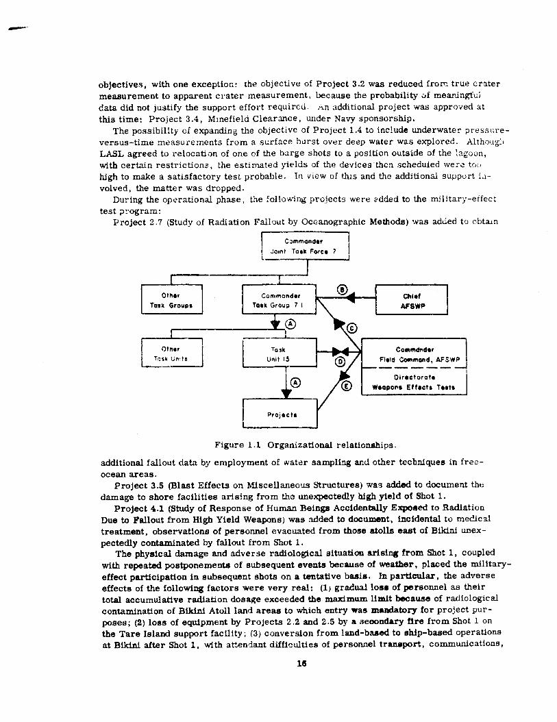
Fig~~e 1.1 Organizational relationships.
additional fallout data by employment of water sampling and other techniques in free-ocean areas.
Project 3.5 (Blast Effects on Miscellaneous Structures) was added to document thedamage to shore facilities arising from the unexpectedly high yteld of Shot 1.
Project 4.1 (Study of Response of Human Beings Accidentally Exposed to RadiationDue to Fallout from High Yield Weapons) was added to document, incidental to medicaltreatment, observations of personnel evacuated from those atolls east of Bikini unex-pectedly contaminated by fallout from Shot 1.
The physical damage and adverse radiological situation arising from Shot 1, coupledwith repeated postponements of subsequent events because of weather, placed the military-effect participation in subsequent shots on a tentative basis. Et particular, the adverseeffects of the following factors were very real: (1) gradual 10ss of personnel as theirtotal accumulative radiation dosage exceeded the maximum limit because of radiologlc alcontamination of Bikini Atoll land areas to which entry was madatory for project pur -poses; (2) loss of equipment by Projects 2.2 and 2.5 by a seoondary fire from Shot 1 onthe Tare Island support facility; (3) conversion from land-based to ship-based operationsat Bikini after Shot 1, with aV.endant difficulties of personnel tranaport, communications,
and equipment handling; (4) severe boating conditions at Bikini during delay periods.which restricbd maintenance of test stations; (5) degeneration of test stations by s~iltspray, humicUty, rain, and intense sun during the repeated postponements of shot daysbecause of weather; (6) changes of shot sequence, sites, and predicted yields; (7) extremevariations in actual and predicted yields; and (8) cancellation of one shot (IZcho\ fo - uduchelaborate instrumentation had been prepared.
1.2 ORGANIZATION AND ADMINISTMTION
The solicitation, review, and coordination of project proposals wras undert~{en in ac -cordance with the basic mission oi the .4FSWP. Ln April 1953, the Joint Chiefs of Stzffaugmented the mission of the AFSWP by directing the AI?SWP “ . , . !o exercise te~~~cal
direction of weapons effects phases of developrner.t tests or other tests of atomic weapons
TA.SL‘: 1.2 FUNDING A3JDCOSTS, MILITARY-EFFECT TEST PROGR.AM.—— _ .—_____
Program Tltlo Initial R&D R&DCosts toFunding 1 Uctober 195’7
..— —.. —
i Blast and Stock Measurements $2200,000 $1,603,1762 Nmlear Radla!ion Studtee 1,400,000 963,851~ Structures, EqApment and MAtsria! 700,000 367,2164 BiomedicsJ Otxdtes 200,000 7,901
6 Ssmlce Equtpmcmtand Techniques 1,211,7S0 1,073,600‘f Long Range Detection8
within any task force organization for tests conducted outside L\e continen~Ud lJnited States”(Reference 4). The mode of implementing this expanded mission for Castle was delineatedin an agreement between the Commander, .Joint Tast Force 7, mid Chief, ,IFSWP (Ref-erence 5). As a part of this agreement, AFSWP formed and manned Task Unit 1.3 (acti-vated 1 June 1953) as a unit under Task Group 7.1 and exercised technical direction bydirect communication with Commander, Task Unit 13, and as necessary with Commander,Task Group 7.1 (see Figure 1.1). At the request of A~SWP ~%efere~e 6), personnel ofproject agencies were ordered by their respective ~ervices to report to the Corrurxmder,Task Group 7.1 through the Commander, Task Wit 13 for planning and coordination con-t rcd during nonoperational phases and for full operational control during the on-siteoperational phase.
The Chfef, AFSWP, supervised the preliminary work on the military-effect program,with the Weapons Test Division performing the detailed coordination. In March 1953,the Commanding General, Field Command A?SWP, was assigned the responsibility forthe technical direction of the program. This res&msibility was discharged through theDirectorate of Weapons Effects Tests, Field Command AFSWP. Durtng the operationalphaee, the responsibility for tichnical direction reverted to the Chief, AFSWP.
1.3 FUNDING
Research and development (R &D) funds were allotted directly to the participating project
20
agencies by AFSWP (initially by Headquarters, but subsequently by the Field Co remand)to meet research and development costi (see Table 1.2) other than those for on-site con-struction and support. These latter coste were met by transfer of R&D funds from
AFSWP to the Albuquerque operations Office {then the Santa Fe Operations Office) of theAEC . Extra-military funds were budgeted and expended by Joint Tack Force 7 as neces-sary to meet the extra- tiitary costs of the pticipating project agencies.
1.4 SUMMARY DATA
Pertinent information for all Caetle ehots is summarized in Table 1.1; shot locationsare noted on the maPS of Bikini arid Eniwetok presented as Figures 1-2 and 1.3- Theyields lis~ed were the lateat and most reliabie when this report was prepared. Minordmcrcpaneies wIU be noted U tlmse are compared with those listed in References 13 and14; bowever, both of these reports were published within a year after the operation wascompleted. The slight revisions brought about by subsequent data analysis were supplied,upon request of Ffeld Commsnd, AFSWP, by the laboratories (References 15 and 16).
chapter 2
BLAST AND SHOCK
The blast-and-shock program was designed to document information on shock parametersin the propagation of the blast wave incident on and through the media of air, ground, andwater. The isolation of the EPG allowed experiments on the effects produced by test de-vices whose yields were in the megaton range. Only limited blast measurement at longranges had been made for Ivy Mike, which was the first megaton device detonated by theUntted States. In a sense, the program was an extension of the Operation Ivy experiments;additional experiments were needed to confirm, explain, or supplement the Ivy data.
A considerable quantity ~f worthwhile data was obtained from Castie participationDespite uncertain yields and shot delays, the program was able to adapt itself to thesechanging situations and achieve most of the objectives which were original] y conceived.
2.1 OBJECTIVES
After Ivy, certain general objectives were defined for blast programs on future fuN-scale tests at the EPG; it was on these requirements that the Castle program was based.It was determined that free-air measurements should be made on devices with yieldsgreater than 540 kt to check the basic free-air curve. Surface measummxmts were need-ed from high-yield detonations to validate the use of height-of-burst curves and thescaling relations in such yield ranges. Of great importance was the doc mnentation ofadequate dynamic -pressure measurements, to increase the knowledge of this parameterin itself as well as its relation to damage. More information was needed on the effectson the blast wave as it is propagated through a nonhomogeneous atmosphere. It was ex-pected that refraction might also be noticed at distant ranges along the ground, becausesuch effects had been observed for the Ivy Mike shot. Considerably more hform:~tioriwas desired on blast effects over and through the water. Little data was avo.ilable todefine shock propagation in very-shallow water or describe the water shoe!: prodwed bynuclear detoriatton over deep water. It was also hoped to obtain data on the transmnlssionthrough the water via the sound fixing and ranging (SOEAR) channel as well as the outlineand activity of the surface water waves.
The Castle shcts were all developmental devices, so that the military-effect programshaci to be fitted to available yields, heights-of-burst, and shot geometry. In all {;=es,the height-of-burst was essentially zero; that is, surface bursts on land, water, Cr Lheato!l rim.
From these general objectives, then, the following specific objectives were evolved:(1) determine air-blast overpressures as a function of altitude and time at relativelyshort distances above high-yield surface detonations; (2) obtain data on the occurrenceof a precursor from high-yield surface detonations; (3) determine the time characteristicsof air-blast overpressure as a function of dis+mce from eurface zero for high-yield weap-ons, in order to conff rm the validity of scaling laws; (4) check the theoretical relationshipbetween dynamic pressure and overpressure and evaluate dynamic pressure as a dam-
$ge Para=ter; (S) ob~n infer-tion on the pressure-time htstory of underwater shockin shallow water for high-yield surface detonations; (6) determine the transmission in
2a
water of acoustic pressure signals generated by high-yield detonations; (7) determinewater-wave phenomena in shallow water from high-yield surface detonations; and (8) de-
termine ground accelerations at distances relatively close to surface zero for high-yielddetonations.
2.2 SCALE FACTORS
Air-pressure data were reduced to stantird conditions — equivalent tn a l-kt burst atsea-level ambient pressure ad to 20 C ambient temperature. The stadard Sachs cor-rections were applied:
14.7Pressure ~ = ~
o
Distance Sd = (~)’’’(;)’”
Time St =“s) ’’’(G%)’” (k)l’s\
Where: W = yie!d of the device, kt
Po = ambient preseure at burst elevaticn, psi
To = ambient temperature at burst elevation, C
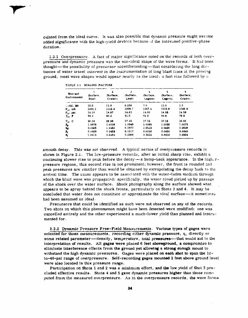
Table 2.1 presents the pertinent scaling factors used in converting the data to standardconditions.
2.3 SURFACE MEASUREMENTS
The significant factor affecting measurements of the blast wave along the surface wasthat all shots in the scheduled Castle series were surface bursts, either on atoll islandsor Iagoon barges, with yields in the megaton range. Considerable interest had beenmaintained in surface bursts; it was ob%ims that more-complete data was necessary toimprove the state of the knowledge. Safety consideration restricted full-scale tests ofeven kiloton-range devices on the surface at the Nevada Test Site. It was hoped thatCastle would supply answers to questions on large-yield surface bursts.
Upshot-Knothole had confirmed the existe me of the precursor, and while its funda-mental mechantsm was not fully understood, its effect on the various blast paran@xwswas quite evident, However, these were precursors from above-ground bursts. Thesurface-burst intercepts of the height-of-burst curves were based on Jangle surface andthe Ivy Mike events as well as the G reenlmuse and Sandstone tower shots. Castle offeredan opportuni~ to check these data, as well as to investigate the possibilities of a pre-cursor forming from surface bursts, even though it was recognized that Nevada precur-sors might not be duplicated under the EPG conditions of atmosphere and ground surface.
Upshot -Knothole also showed the fallacy of assuming side-on overpressure in the pre-cursor region as a basic damage parameter to drag-sensitive targets. It was found thatoverpressure and dynamic pressure were not affected in the same manner by the precur-sor: dynamic pressures were not only considerably greater than those calculated frommeasured overpressure but were even greater by factors of two to three over those cal-
23
culated from the ideal curve. It was also possible that dynamic pressure nught ass-:me
added significance with the high-yield devices because ~f the increased positive-phaseduration.
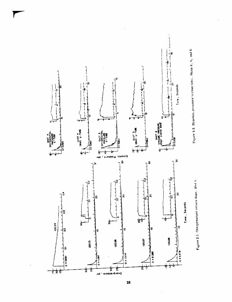
2.3.1 Overpressure. A fact of major significance noted on the records of both over-pressure and dynamic pressure was the non-ideal shape of the wave forms. It h:d beeni.f-lought —the possibility of precursor notwithstanding-that considering the Iong dis -tances of water travel inherent in the instrumentation of long blast lines at the provingground, most wave shapes wouId appear nearly w the ideal: a fast rise followed by :1
s mootb decay. This was not observed. A typical series of overpreesure records isshown in Figure 2.1. The low-pressure records, after an initial sharp rise, exhibit acontinuing slower rise to peak before the decay — a hump-back appearance. In the !ligh. r -pressure regions, this second rise is not prominent; hGwever, the front is rounded mdpeak pressures are smaller than would be obtained by extrapolating the decay back to thearrival time. The cause appears to be assoc! steal with the wuter-laden medium throughwhich the blast wave was propagated: specifically, the water cloud picked up by passageof the shock over the water surface. Shock photography along the surface showed whatappears to be spray behind the shock fronts, particularly cm Shots 2 and 4. Itmay heconcluded that water does not constitute or approximate the idea! surface—it sometimeshad been assumed as ideal.
Precursors that could be identified as such were not observed on any of the records.Two shots on which this phenomenon might have been detected were modified: one wascancelled entirely and the other experienced a much-lower yield than planned and instru-mented for.
2.3.2 Dynamic Pressure Free-Field Measurements. Various types of gages wereselected for those measurements, recording either dynamic pressure, q, directly orsome related parameter —density, temperature, total presmuws— that would aid in theinterpretation of results. All gages were placed 6 feet abowground, a compromise toeliminate interference effects from the ground yet allowing a strong enough mount towithstand the high dynamic pressures. Gages were placed on each shot to span the 10-to-40-psi range of overpressure. Self-recording gages mounted 3 feet above ground levelwere aleo located in this pressure range.
Participation on Shots 1 and 2 was a minimum effort, and the low yield of Shot 3 pre-cluded effective results. Shots 4 and 5 gave dynamic pressures higher than those com-puted from the measured ove rpressure. As in the overpressure records, the wave forms
24
were quite distorted end non-ideal M titir, M shown in Figure 2.2. All of themgage stations were locamd near the sdge of the water, exoept for the measurement onShot 6 which was prece~d by some 800 fed d blast travel over an island surface; thelatter record showed only a slightly ~ mve form with a peak dynamic pressurein good agreement with that value c~ *m the measured overpmmeure. For thosedynauic pressures -MUrd nar the ~ ~ * -r, it ~ ~ that the blsetwave picked up watm droplets which ~~ to tba disturbed appearance of the waveform and that water is I@ an idsd sufao..
The primary objective in tuking e~~~ memmrementi was a study of thatpressure-time records to aheck * tlxwdbd relatiom bstwwn dynamio pressure and
gmgm Are ●lmtrdo gqpa ~ b Pr@q l.a (SC).tbfaxhum wlwofqwtdohls ldoatadlnreuxxuradata la49rttmwthmmaxt-
InuLnV81uoof ap.
overpresfmtre. From a somewhat-limlted quanti?y of data, it was found that the relationdid ?mt hold where the path of the blast wave approaching the gage Wation was over av:ater surface. Table 2.2 shows a comparison of measured and calculated values of dy-namic pressure.
2.3.3 Dynamic Pressure as a Damage Parametsr. Jeeps were used as representativemodels to investigate further the role of dynamic pressure as the damage parameter toconsider for drag-sensitive targets. Participation was planned for two shots, one ofwhich was cancelled; actual participation was accomplished on Shots 3 and 6. The lowyield of Shot 3 gave low dynamic pressures and consequent light damage to vehicles.Satisfactory damage — light to severe — wae attained on Shot 6.
The limited data obtained were not conclusive enough to permit an evaluation of dy-namic pressure as a damage parameter to be applied to the jeep as a drag-sensitivetarget. The response of such a target depends on the loading, which is a function of bothdynamic pressure and duratioil. The results obtained did not allow a separation of theeffect of the one damage parameter fnm that of the other.
Furthermore, it was not possible to determine specific levels of dynamic pressurefor ~fferent degrees of damage. Consequently, it was difficult to just@ the cube-root
2s
J
Isd L aJI)SSOJd CI!UIou~O
i
*&J
L1. ] -401 “---!0 + 7. 1 1.11-
26
Iscaling for vehicle damage proposed by Project 1.8, since this attached importance onlyto dynamic pressure. Castle data was ~ized in the preparation of a corqxmite AFSWPreport (Reference 12), which showed that @“’ scaling is the most-appropriate methodfor predicting damage to military field equipment.
2.3.4 Effects of Ratn. Ground zero of Shot 3 and most of the Tare complex to the eastwe~e covered by heavy clouds with accompanying shower activity at zero time, a situationwell documented by radar, photography, and transrnissivity measurements. Althoughthe low yield of this shot failed to satisfy many of the program’s objectives, very inter-
Figure 2.3 Overpressure versus ground range, se measured for Shot 3.
esthg data was obtained that appears to be directly associated with the presence of highmoisture content in the air.
Two instrumented blast lines bad been established on bearings approxirnat.dy 180degrees apart — along the Tare complex eastward to Oboe Island and westward throughUncle Island. When the data had been reduced and plotted, it became obvious that ananomaly existed: pressures obttined from the Tare line were somewhat lower than thoserecorded by the Uncle gages.
Possible correlation of this effect with low clouds or rain was suspected when theradar-scope photography disclosed that Uncle and that area immediately to the west ofground zero was relatively clear, while a solid return over the Tare complex indicatedheavy clouds and, possibly, actual rain.
Figure 2.3 shows a plot of pressure data from both lines. Project 1.2b instrumentedthe east and west lines with self-recording gages, while Project 1.2a covered only the
27
Tare complex with electronic gages. There was a definite and consistent variation 111the data between the two lines.
It is recognized that a moisture-laden tir will attenuate pressures in ‘Ac blast wave,simply because blast energy will be lost by an amount proportional to that which is nec -essary to evaporate the suspended water droplets or rain in the path of the shock. Studieson the problem by the tw projects concerned indicated that a moderate sh~we r couldcontribute sufficient water content to the air to account for the deviation in the pressure-distance curves of the two Mast lines (described in the Project 1.2a and 1.2b reports,see Appendix).
2.3.5 Comparison with the 2W Theory. It was anticipated that sufficient data wouldbe obtained %’om Castle to allow a quantitative comparison to be made, for surface bursts,with the ideal case. Theoretically, such a burst over a perfectly reflecting plane shouldact like one of twice its yield in free air. Data from prevfous surface bursts, JangleSurface and Ivy Mike, did not entirely confirm MS theory. The question was the value
of the reflection factor — of necessity between 1 and 2. From Castle data, it appearedto be certainly less than 2 —probably between 1.6 and 2.
The difficul~, and the reason a more-definite figure cannot be assigned, lies withthe determination of field of the multi-stage devices; firebaLl and time-of-arrival meth-ods used to estimate yield involve the 2W aesumptton. A method independent of this as-sumption is necessary. Unfortunately, only radiochemical analysis, which determinesonly the fission yield of a device, satisfies this restriction.
Figure 2.4 shows a pressure-distance plot of all the surface overpressures scaied to1 kt at standard sea-level conditions, along with simflar data from Ja@e Surface andIvy Mike, compared to the 1W and 2W free-air composite curves. AU measured datawere scaled to 1 M at sea-level conditions. The solld line represents a compositepressure -distance curve for a 1 -kt surface burst based primarily on Castle measure-ments. Yields used for data reduction were based on a radius-time history of t.ke fire-ball (involving the 2W assumption)i. All arrival-time data are compared m Figure 2.5on a similar basis.
There were no apparent effects due to refraction obsewed during Operation Castle.In fact, Figure 2.4 indicates that overpressures at long ranges fall closer to the 2W free-air curve than do overpressures at closer ranges.
2.4 ABOVE-SURFACE MEASUREMENTS
The results of Ivy King confirmed the scaling laws for free-air pressures up to ayield of 540 kt. Data obtained from the bf.ike event, however, wure confined to the low-pressure region. There was reason ta suspect that for high @eIds, an altitude correctionmust be made for propagation vertically through a nonhomogeneous atmosphere. Castle,then, presented an opportuni~ to document pressures in the ah above megaton-yieldsurface Ada. These phenomena include a definition or delfnestlon of the shock from asurface burst as it propagates through the low levels of the atmosphere out to long ranges.
2.4.1 Pressures. The smoke-rocket ad dfreot-shmk photography techniques wereused for pressure-distance determination in the air ad along the uurface. b generrd,
i On Redwing, considerable data was obtained from two land-surface bursts, one a kilotonburst of medium yield determined by radfochemfcal analysis. A composite land-surfaceburst curve was drawn from the data-it scaled about 1.6W.
2$
results were satisfactory. However, cloud cover, usually present at low altitudes overthe EPG, made it difficult to obtain photog~phy to the desired degree of success. How-ever, this lack of data was supplemented by the use of less -accura~ data from photo-graphic film from another source. No film waa usable from Shot 3 because of the lowyield of the device and the poor visiMlity at the time of the shot.
Pressure-distance data vertically above the shot were obtained only on Shot 2. Be-yond the fireball, data waa measured tn the region from 10,000 to 15,CO0 ieet. Two wavefronte were aleo observed it va’y-high altitudes (-265,000 to -335,000 feet). The firstwave probably was the hlwxt wave; the EXWOrdwas presumed to be an acoustic wave. Thelow-altitude (10,000 to 15,000 feet) data are plotted in Figure 2.6; these data are compared
t
i-—--- : ‘.
k\\\.————.--’
-——.—
,._—_
Figure 2.4 Composite overpressure versus scaled ground rmge, Shots 1 through 6.
to theoretical pressure-distanCe curves which were constructed using the ‘Theilheimer-Rudlin Naval Ordnance Laboratory (NOL) method for considering the variation of thepressure-distance relation with altitude, which involves the determination of an equiva-lent TNT charge radius. The upper theoretical curve for Shot 2 in Figure 2.6 is basedon an average change radii of 404 feet for the surface -level data obtained by Project 1.2awiti electro~c g~es. ‘1’helower theoretical wave is based on an average charge radii
of 349 feet for the surface-level data obtained by Project 1. la with rocket-trail photo-
29
Ek
1.01..-0 NOL
}shot I
h Sc
● NOL Wafsf Surfocae NOL Lend Surfoc@
& Sc
6 Sc — shot 3
e ‘OL ~Shot 4&sc J
A SC — Shot ~
● IvYMlko. Jor)Jlo
1
Jshot 2
, I
I i I I I &
0:
:
7)
:!-
Figure 2.5 Composi@ ecaled time of srrlval versus smiled ground range,shots 1 through 6.
30
graphy. Consequently, an average charge rtii of 376 feet were used, which comparesfavorably with the average charge rdi.i of 387 feet computed for the Ivy Mike surface-level data obtained with electronic gages. TIM pressure-distance curve for these equiv-
alent TNT charge radii was then soaied vertioal.iy by the NOL method tor comparisonwith measured data, using the obserwed ambient conditions at altitude. The uncertainty
of the measured data ww suoh that it was not possible to correlate the verticai peakoverpressures with the theoreUoal cunme derived from the surface-level peak overpres-sures in this manner. Conaeq~, itwas wt possible to determine the tist method
of making an aititude correction to moocmt for W8t propagation through a nonhomoge-neous atmospbe re for high-yield bursts.
Those pressure * meaaured along tbe surface, obtained on Shots 1, 2, 4, and 6 byasing smoke-rocket and direct shook photography, are plotted In Figure 2.7. Gage datafrom Jangie Surface and Ivy MUse bavo IXMXI included for comparison and correlation.The data were normalized by eeal.tng to 1 kt at 8t8ndard sea-level conditions, so thatthe composite free-air data scaied to 1 ad 2 kt could be shown. A comparison to the1- or 2-kt free-air curve for the purpose of determining a reflection factor for surfacebursts was not strictly vaiid, since the hydrodynamic determination of yield for theseshots ixwolved an assumption of the factor of two. (Discussion of the surface-burst re-fiectiou factor was presented in Section 2.3.5. ) Figure 2.8 shows scaied arrival-timedata obtained by smoke-rocket and direct shock photography, with the 1- and 2-kt com-posite free-tir curve. Scaled data for both pressure and arrivai time appear self-consistent, as well as comparing favorably with Jangie and Ivy gage data. It seemsjustified to conclude, then, that cube-root scaling of blast data from events in this yieldrange is valid.
Part of the objective of the direct shock photography was to observe the formationand growth of any precursor which might occur. At this time there was some doubt thatthe precursor wmld form on a surface shot. Actually, no precursor as such was noted;however, anomaious wave forms were recorckl by the pressure-time gages. Observa-tions made of the film exposed on Shota 4 end 5 disciosed a dense water cloud followingimmediately behind the shock front. This clod implies water droplets contained in theshock front and may explain the anomaiy.
2.4.2 Base S..wge. Early planning provided for the detsrmfnation of the characteris-tics d the base-surge phenomenon for eao.h of the shots. It was hoped that from such adudy, scaiing laws could be formulated to predict base-surge effects of surface shotswith yields different from those of Castle. The base surge becomes of military signifi-cance when it acts as a carrier of radioactive contamination to regions beyond normaifallo’. The extent to which this could occur from surface bursts, as well as the generaidynamics of the phenomenon and the determination of scaiing laws, were the objectivesof thi S study.
The experiment was almost entirely unauccessfui, since the primary analytical tool,photography, was rendered useless when it was decided to schedule the shots beforesunrise. A minimum photographic effort was maintained throughout the series, fromwhich it was determined tit a base surge probably did form on Shots 1 and 2. This
limited material prevented any detailed study anticipated in the early objectives.
2.5 CLOSE-IN GROUND ACCELERATIONS
Study of ground motion produced by muitimegat.on devices detonated on the ground sur-face was planed for Castle to emend ~d supplement those data obtained from Ivy Mike.
31
.,
The primary interest wss in motion closer to ~o~d zero than previously instrumented.Participation was planned for two shots, boti to ~ detonated on atoll islands: one at
Bikini, one at Eniwetok. Measurements were obtained on Shot 3; however, the unexpect-
ed low yield of that event (Morgenstern) forced cancellation of the other shot (Echo) forwhich measurements had been phmned.
The instrumentation layout for Shot 3 consisted of vertical, radial, and tangentialcomponents of acceleration in the ground below the water table at ranges correspondingto 200-, 100-, and 36-psi peak air overpressure predicted for a l-Mt yield. As a reswcof the low actual yield, set ranges for the gages were too high, recording a very-lowsignal amplitude. With suoh a low signal-to-noise ratio, the identification of phase ar-rivals, frequencies, ad amplitude8 was uncertain. The results are given in Table 2.3.The curve of arrival time versus range is shown in Figure 2.9. The sir-induced signal
TAst.a 2.: Acccmm MTA
170.01 2,5s4 33 v No ttmord
33 E 031 0.B4 0.47 42 0.63 3.44 4.10 m23 T 0.31 130 1.11 45 066 2.20 4.87 100
propagated with a velocity of the atr blast wave, decreasing with increasing groundrange. The ground-transmitted shock propagated with a velocity of about 8,700 ft/sec.
The determination of velocities and displacements by means of integration of the ac -cele ration traces was not attempted because the quality of the data was too poor to sup-
port such analysis. Also, the ground motion was too small to produce significantstructural damage.
z G 7JFiDERWATER MEASUREMENTS
Propagation of shock waves in shallow water was not weli understood. CrossroadsBaker and ivy Mike had been instrumented with underwater mea surementi. Baker re -&uIts did not define the underwater pressure-time history with any degree of accuracy,hut they did estab!iah the order of magnitude of the pressure decay as a function ofrange. No significant data were obtatned from Mike. Castle offered the first opportunityto document the underwater pressure-time hfstory from a nuclear device detonated onthe surface of the water. Actually, the geometry of ground zero for the Castle seriesof shots — represented by the lagoon bottom and the atoll rim-was quite complicated,involving a condition not well understood. However, such geometry did represent con-ditions of practical mtlitiry significance: (1) air attack against a submarine in shallowwater, (2) an attack against shtps in harbors as well as the harbor facilities, and (3) at-tacks against dams or mines.
The specific objectives of this project included measurement of underwater pressureas functions of time, distance, and depth for large-yield weapons detonated at the sur -
Figure 2.8 Surface arrival-time data scaled to 1 kt at sea level.
2,4
t
“Ot- )’43S0?T/BEC
~ MwOE, ~T
Figure 2.9 Earth-acceleration arrival daea ver~ grcnuni range for shot 3.
34
face in hallow water- In addition these data were to provide for comparisons with aAw.llow underwater burst (Crossroads) ~ a deep underwater burst (Wigwam). At thesame time, this operation provided an opportdw to check out instrumentation and ob-
tain experience in making underwater measurements that proved valuable m preparingfor Operation Wigwam.
2.6.1 Underwater Pressures. Three laboratories jointly participated in this project,under the sponsorship of the Offioe of Naval Research. Some difficulty with h@rumenta-t ion due to repeated delays was experienced by each agency during the operational phase;as a result, a lesser amount of relhbIe data was obtafned than originally anticipated.However, sufficient measurements were recorded from the five even~ to allow someconclusions to be drawn.
The major result of the recorded data indicated that except for the close-in region,the maximum, or peak, underwater pressures were of the same magnitude as the air-biast peak overpressures at the same range. The maximum underwater pressures re-c srdeci were probably not due to the air-coupled shock alone, but included some of theseismic and the direct water-borne shocks as well. However, this comparison breaksdown for the region close in to surface zero. The exact range where the dissimilarityof pressures becomes significant appears ta be a rather-involved function of yield,water depth, and relative depth oi the target.
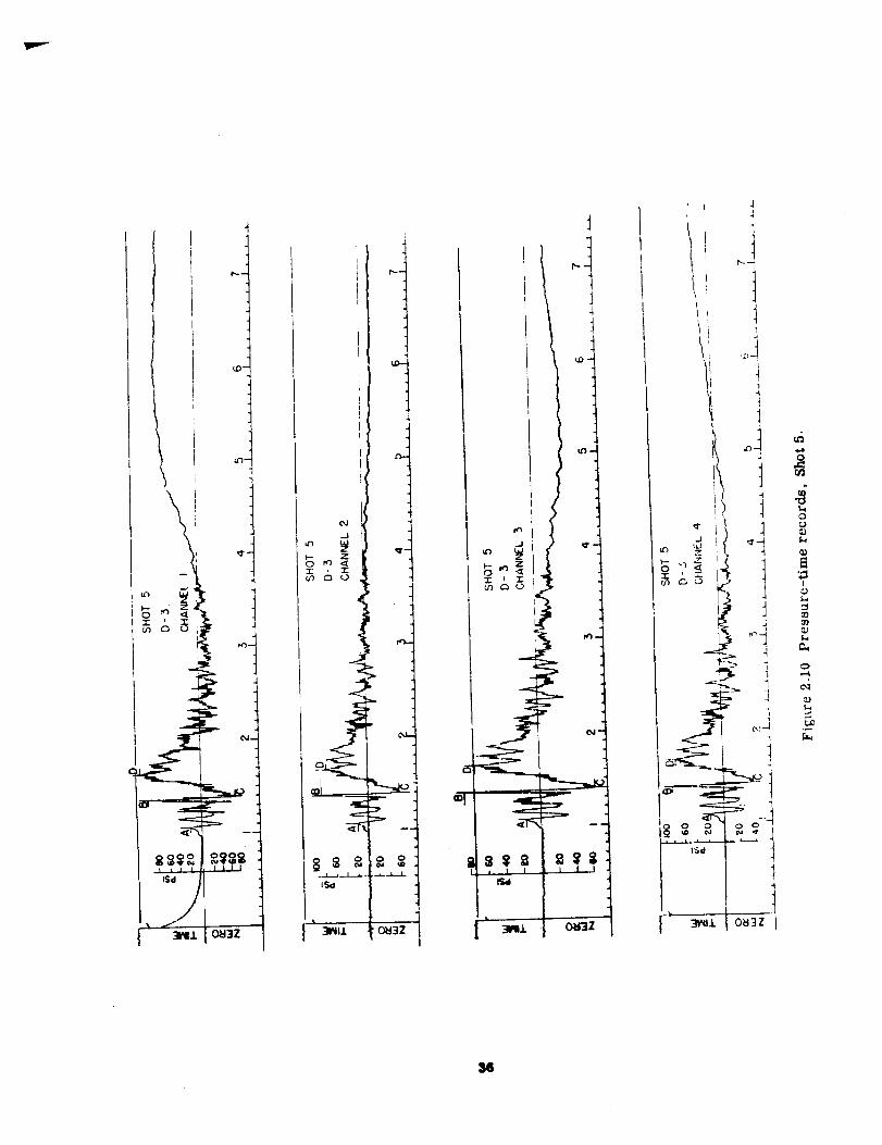
Figure 2.10 reproduces typical pressure-time records. All records of this @e fol-1owed a similar pattern: an initial disturbance followed by several positive and negative
p@es. followed by a slow-rising signA caused by the air-blast wave passing over thesuface. This iatter arrival was confirmed by air shock-arrival times. The initialpositive disturbance, with its succeeding pulses, travelled with average velocities fasterthan might i>e expected for transmission of underwater shock, and it is believed theywere transmitted through the ground and reflected from various subsurface strata. Thevalues {Jf presslme and time after zero were measured at each point !abeled A, B, C,etc., and entered in Table 2.4.
Figure 2.11 shows a plot of data obtained with two ~pes of gages: the ball-crusherU3C) and the pressure-time @t). These data are a composite of measurements madeon all shots and at various depths, and have been normalized to 1 M. The included curveis the 2-kt composite free-air pressure-distance function, approxi mating a surface burstof 1-M yield. The measured (scaled) data show a fair fit to the free-air curve.
It vim concluded that a nuc Iear device detonated on the surface of a relatively shallowwater layer prodwes underwater pressures which are probably of smaIl military sig-nificance, because: (1) although they are of comparable magnitude to the air-blast pres-sures, typical underwater targets a.’e, by their very nature, of such strength that theyrequire pressures ‘which are at least one order of magnitude larger than air pressuresROrrna)LY considered as damaging; and (2) they are insignificant compared to pressures
produced by underwater bursts such as Crossroads Baker or Wigwam.These conclusions must be qualified, however, since they are based on results ob-
tained under the specific environment as experienced in the Bikini and Eniwetok Lagoons.Different conditions will probably produce different results.
2.6.2 Acoustic Pressure Signals in Water (SOFAR). The presence of a low-velocitysound channel at a depth of 700 fathoms in the AtJ.m-itic and at 350 fathoms in the Pacificis well known. Low-frequency sound channeling into this layer wi].1 travel great distances.It is also possible for sound to travel long ranges through the water by reflecting suc -cessivley from top to bottom of the ocean — both boundaries being excellent reflectors
35
\
\!.I
I
is
1
I
!--k!w
=1 0M3Z
I
LC&ol-i-
lSd
3W11
I
--+--lMl 0H3Z
0N
J-l-3W11 (3M3Z
97
for low-frequency sound waves. Some success had been uhieved during both Greenhouseand Ivy in detecting SO FAR signals transmitted through the water. Relative yields werefairly well established from signals received during Greenhouse at one of the detect] ngstations. It was planned to again activate these remote stations for Castle to makespecial observations of acoustic pressure sigmls of the SOFAR type, to add to the knowl -edge of underwater sound propagation, and to investigate the possibility of determining
yields.
Shots 2, 4, 5, and 6 were monitored by detecting stations located on the Californiacoast and at Bermuda. No clear-cut signals were recorded which could be attributed to
TASLE 2.4 SUMMMIY OF PRESSURE-TIME DATA, SHOT 6—
BUOY D3 , 9 ,300-ft Buoy Al, 16,100-ttDtstance Diotic e
BllJ? 130x o 0from ZeroPremure Arrival 0.97 0.97‘rim, seo
Premure A. ~i 19.27 18.2‘rime, * 1.06 1.06
PreBeulw B, psi 83.7 84.2‘rlrm , ●ea 1.38 1.37
Precmlro c, pm -74.7 -68.6‘rlnm, aec 1.40 1.40
Prt?omm D, PSI 08.4 7s‘N me , Sec 1.64* 1.65*
Pre98ure E, pti — —Tiam3, am — —
t3u.g8 PE PEAmpllf.fer 106 Iin
o
0.96
16.31.05
64 .!!1.S6
-821.39
72.21.84*
——
PElint
o
0.96
17261.06
84A1.36
-36.61.40
76.1l.~.
——
PElogt
2.14
1.17
17.41.66
-28.91.6916 .S1.24
1S .762.37
324.90*
PE
2.08
— 1.67
— 24.2— 1.78
— -3S.8— 1.83
— 24.2— 1.89
25.3— 2.30
— 20— 481*
Wieackot W!6ncko— —.
‘Air blast,based on arrival time.taame pge.$ Equipm4rI?inoperative.
sources at either Bikini or Eniwetik. It is concluded that the position of tie shots insidethe lagoon end on the atoll rim was such as to preclude coupling of energy into the SOFARchannel in the frequency range for which instruments were available. Another factorwhich might have prevented reception at the California stations was the presence of shoalareas between the Bilrhd atoll and the coast along the most likely path of travel.
2.7 SURFACE WATER WAVES
The effeots of water waves resulting from megatin-yield detonation at the surfacecould have military significance for (1) generation of waves in harbors causing damageto secured. veesele, docks, shore installations, eto. and (2) long-range propagation ofLsunami-lfke waves from a source over deep water, which could produce serious damageover extensive coastal areas.
The only previous full-scale data on watar waves generated from a megaton surfaceburst had been obtained from Ivy Mike. No measurable waves were produced in the
central region of the detonation, yet waves which were of measurable amplitude wereobserved at a range greater than four miles. These waves increased in height out to a
98
distance of approximbly 26 miles end arrived M thou@ genera~d C1OO8to grouad sero,hating travelld across the lagoon at the vel-ity of smlow water waves. Sf22C8Ivy Mikewas an island shot, it wae not wholly surpris~ that it did not generate wavee in a mannerMLSJWKOUSto high expbivee &to- on water. Altiough the M.ib shot W resoh intothe ~dgoon, the generation ad coli~ of ti catim was not comi&* b be Wmtld tothat from a buret on water. Therefore, it was believd that the ehot envl~t oan-
celled out most of b dira3t generati- region.In contrast to the Mb rodte, Castle date itio~ thatthe reoo- wavee did ema-
nate from the central rqghm of tb detonation. The firstarrival was a dmti~~d,
highly damped series et gruad- or water-trmsd~ etmoks.Following them , the
Trmml-2 *1 “Fro.Air
from wT- 710
1I00
I I
1 I o B/cr A “A P-T Geqb -
.-*a
.l-u_ulL,“ I I I I I I I
I I 1 1 I 1 1-
7 moo 2000
Horizontal Range , Feet
( Scoled to I k)]
Figure 2.11 Averaged pressure-ds~ce da~.
records clearly showed the arrival of the air-transmitted shock wave.Next, preceding
the direct water wave, a slow rise in pressure (water) occurred that was postulated tobe caused by large quantities of water and coral debris falling back to the water surface.This was abruptly lost in the arrival of the direct water wave — the first arrival in allcases being a crest followed by a trough.
These appeared to act as oscillatory waves,
the time of arrival of the first crest showing a propagation velocity fitting the relationV . (gh)l/2, where h is an average depth of 170 feet assumed for the Bikini Lagoon.
Refraction and reflection against a reef or shore line may significantly reduce or am-plify the destructive capabilities of water waves at termination. At Bikini, How Islandis an example of a protected shore, while Nan is an example of one highly susceptible to
39
amplified inundation. Where foousing effects and the reflection-refrution pob=mtial of theadjacent lagoon topography are a minimum, the heaviest inundation and Potential damagecnxmrs with the first crest.
Unfortunately, these results were highly ~que: they were obtained under particularconditions of geometry, in a region of relatively shallow depth. The conclusions areapplicable to conditions which depart only slightly from these under which the data. wereobtained.
Waves were also recorded at a few distant islands. However, the results were meagerand inconclusive, and a better interpretation can probably be made if held for a synergisticinclusion with the results of the distant-island phase of the Redwing studies.
Chapter3
/VUC[EAR -RADIA1701VtWEASUREtWtWS
AND FALL(W W491ESThe nuclear-radiation program had two major ohjectfves: (1) the documentation of thell~tid radiation, neutron and gamma, from megaton-range nuclear detonations and (2)the documentation of failou~ from land-surface and water-surface bursts of multimegatondevices.
The unexpectedly high yield of Shot 1 had two influences on the execution of the pro-gram: First, much of the spare equipment was destroyed on Site Tare, ad instrumenta-tion for subsequent shots was curtailed. Second, the importance of fallout in terms ofeffects of military significance over large areas beyond the blast- and thermal-damage~rlvelopes was demonstrated dramatic a.UY. This realization, together with the observa-
tion that activity dissolved in sea water could he a measure cf the fallout int.ensi~, pro-vided the impetus fol tie water aud aerial surveys that yielded valuable data after Shots5and6.
Prior to Operation Castle, only one maltimegaton detonation had provided data onnuclca~.. radiation effects — Shot Mike of (lperaticm Ivy. The initial-radiation data con-sisted of records of initiaA gamma versus time at two stations, total initial-gamma ex-posure at a number of distances. and a few neutron-flux measurements using Au,and [ activation detectors. There had been an extensive array of fallout-documentationstations LOP+ the isiands and in the lagoon of Eniwetok Atoll; however, these collecteddata or, the crosswind and upwind fallout only, since the more-extensive downwind falloutoccurred on the ocean toward the north.
The fallout from the few kiloton-range surface and underground shots prior to Castlehad also been documented. Measurements of initial radiation from fission devices up to500 kt had been performed extensively. The initial-radiation data were not adequate
prior to Castle because (1) the scaling laws are not simple and do not lend themselvesto extrapolation from kiloton-range to multimegaton yields and (2) the neutron dose fromneutrons in the ener~ band above thermal hut below 3 Mev had not been measured dueto the lack of detectors with thresholds in this region. The objectives of the Castlenuclear- radiation experiments were aimed at obtaining data to eliminate the deficienciesmentioned above. In particular, the objectives were to document for multi megaton land-surface and water-surface detonations (1) distribution of fallout; (2) physical, chemical,and radhchemical nature of fallout; (3) rate of delivery and total initial-gamma radiationat v?. rious distances; (4) energy spectrum of and dosage from neutrons at various dist-ances; and (5) the applicability of fission threshold neut: ~n detectors and germaniumneutron-dose detectors.
The total exposure from initial-gamma radiation was detected at a number of locationsusing film-badge and chemical -dosimeter systems. Only a part of the anticipated datawas obtained because of extensive destruction of stations and supplies during Shot 1.
41
The xneasuremenw, includng two points c~c~ated by integrating gamma-rate recordsfrom Shot 4, are presented in Figure 3.1. Prediction curves (from Reference 7) a~.d
measurements during Greenhouse and IVY (References 8 and 9) are also presented forcomparison.
One record of initial -ganuma rate versus time up to shock-arrival time (0.9 seconds)was recovered after Shot 1. TWO complete records (illustrated in Figure 3.2) were re-covered after Shot 4. The shock-arrival times interpolated from Project 1.1 data are
“- l_u..i3ml-- ,-k-lJ-lk--: l\+---t--i-- -~
L>$’fw1+:–ii)
Greenhouse ~l\i I -j-
103 0.08 MT -—— ——~:---
-— —..— —. -—
—.—- -. —.
=!=ti-+=&+ “: ‘i —
I-+-t--!-+-i-i+r+ —--k-M-L--+
I \~I01 ; 05SMT
lx r ,1 1 t I 1 , , — —1 -ml I \l \ 1 1—
( 1 r ( L 1I n I \l I 1r I 1 I I
,oJ- Iti i’\l I’h JJo 10 20 30 40
Range , 102 Yords
Figure 3.1 Initial gamma exposure versus distance.
indicated on the figures. Apparently, this time is associated with the break in the slope
of the gamma-rate curve. The integration of these curves indicates that the exposure
at the 7,171-foot station was 1,000 r before shock arrival and 16,800 r after arrival.
The corresponding exposures at the 13,501-foot station were 14 r and 109 r. Therefore,
42
\
i-l
Time , Seconds
Figure 3.2 Initial gamma-exposure rates, Shot 4.
43
only 6.4 percent and 11 percent of the total exposhres were delivered before shuck ar-
rival at these two stations.
3.2 NEUTRON RADIATION
The basic neutron-flux measurements were made with activation detectors whoseindicated effective thresiioli energies were:
Detectcr: Au, Au-Cd Ta, ‘r~-cd S
Threshold: <1 ev < 1 et? > 3 Mev
Additional measurements were made with fission detectors and germanium crystals,primarily to test their usefulness. The fission detectors were used in two ways: count-ing fission fragments in a photographic emulsion and counting gamma activity frc~l fis-sion products after recovery of the samples. ‘T& fission detectors used and ti)eir
The Shot 1 data from the activation and fission detectors are summarized in Figure3.3; the fission detector data from Shot 2 are illustrated in Figure 3.4. The germardumcrystal (Ge) dose data agree in order of magnitude with the threshold detector data.There was a large scatter in the Ge data, indicating that the detectors were not reliablem the form used.
3.3 FALLOUT DISTRIBUTION
3.3.1 Instrumentation. The following procedures were used to furnish informationon the distribution of fallout activity after each of the Castle shots (some of the collectorsalso provided samples for chemical, physical, and radlochendcal studtes of the falloutmaterial):
1. Survey readings were taken by project personnel ad the Rad-Safe organizationat island stations at various times after the shots.
2. Readings of total residual-gamma exposuw at island stations were taken fromfilm badge and chemical dosimeters.
3. The activity of samples from total fallout collectors WSE related to the infinite-field exposure rate by normalization at island stations. Total collectors of the funnel-and-bottle or gummed-paper type were placed at island stations, on rafts anchored inthe lagoons, and on free-floating buoys plaoed north of Bikln.i Atoll during the last fewdays before shot time.
4. Garnma-exposure-rate recorders were plaoed at some island stations to providedata on the time of arrtval, rate of arrival, peak actlviw, and decay of fkhut.
5. Incremental fallout collectors were used to collect samples during 5- to 30-minuteintervals and to provide data on time and rate of arrival of fallout.
6. After Shot8 5 and 6, surface and aerial sarveys of the oaeaa fahut area were per-formed to measure the activtty in the surface hyer of the eoeaa ad itsdepth of penetra-tion. The existence of a mixed layer in the ocean down to the timrrnooline, with littlemixing below, enabled these measurements to be related to tha total aotivity deposited.
i rkpendfng on amount of BIO shielding around eampie.
44
3.3.2 Shot 1. The data gathered by the Bikini Atoll surveys and collectors were sup-Plemented by surveys ~erformed cm the atolls that were unc~ectedIy contaminated. ‘rhe
major portion of the pattern, which occurred over the open ocean, was not documented.
However. ~ an~ysi~ of the And structure d~fing hf’ i~llwt period was ,mrformed; this
TABLE 3.1 AREAS OF AVERAGE RESIDUAL(3A?MMA ACTTVI?X
.— .— --
ShotL AreaAve r~ HeisiduejGunme AcUtl~
.— -~a r,%rntl!+lhr
2,040 3,000
2,880 2$00
3,850 i ,600
6,030 700
12,900 300——●see UT-916, AFQondtxF.
analysis, combined with the available data points, produced the pattern exhibited inFigure 3.5.
The time of arrival of fallout at the Bikini Atoll stations was between 1S and 45 minutegaf&r detonation. Statements from persons accidentally exposed on downwind atolls in-dicated an arrival time of 8 hours on Rongerik Atoll (at a distmce of 126 nautical miles)and of about 18 hours at Uterik Atoll (300 nautical miles). The data from lxvo measure-
.a - .UL8anl
Figure 3.8 Reconstmcted complete fallout pattern, Shot 1, (r/’hr at H + 1 hour).
ments of residual gamma versus time at nearby stations are presented in Figure 3.6.The decay exponents estimated from these graphs are between 1.1 and 1.4 for Station220.12, and 0.81 for Station 220.08. (Decay exponent is defined as x in the relation forexposure rate I = 11 t-x, where t is the time. )
Table 3.1 presents the data on contour areas. From this, a rough activity-balance
@ pf. M Wd
calculation indicated that about 50 Pement of the activity was accounted for in the falhYt8pnttern.
3.3.3 shot2. Bikini Atoll was not heavily contaminated after shot 2, sinoe the winds. —..
carried most of the activity towaml the northwest. some data were availshle from thefree-floating buoys, but they were not sufficient to proch.we reliable contours. The max-imum reading observed at 35 miles from ground zero correspotid to a land readi~ of
!000 , I [ 1 f I 1 I 1..- ! 1 I 1 I
I 1 1 I ! u!!1 Sidmm 22012 M
C/l I _ Total EC-O @It \ 4.4. !!t
25 Hours * 3735rI w i
~ L –-L--2+$%2
Ii.-..—+1 , ,
! [ I Ill I I P_.— [ 1_& I 1 u—-+++++
1.010.1 10 10 20 30
lime , Hours
F!gure 3.6 Residual gamma rate versus time, Shot 1. Upper curve:Station 220.12
on Dog, Q ,3472feet to ground zero. Lower curve: Station 220.08 on Oboe, 83,762
feet to ground zero.
435 r/hr extrapolated to H A 1 hour. Rad-Safe readings on Sites Able and Charlie near
ground zero indicated readin~ of 4,700 r/hr and 1,100 r/hr, extrapolated to H + 1 hour.The other islsnds received exposure rates of less than 25 r/hr at H + 1 hour.
3.3.4 Shot 3. The fallout pattern from Shot 3 was ideally located with respect to theme=m=titions. The shot was hxated on Site Tare, on the south edge of the atoll,
47
and the fallout was directed northward, intercepting the anchored lagoon stations and tirmnorthern islands. The close-in fallout pattern is illustrated by the data pcints and ez -timated contours in Figure 3.7. Since the yield ~f the detonation was only 1.30 kt, thispattern represents a large fraction of the total fallout.
One gamma-rate record was obtatned f rem. Site Dog, indicating 2 dec zy exponent of
residual radiation between 1..1 and 1.25. The fallout arrived at ab(jht H + 2:1 mimites,and a -mum exposure rate of 23 r/lx vas observed at H + 40 mirmtes. The in~~gratedexposure till H + 15 hours was 51 r.
3.3.5 Shot 4. Most of the Bikini Atoll stations did not receive appreciable faiioutdum~o~~ The shot location and the winds loca.lizsd t~e radiation levels of mil italni’.signi ticance to the northeastern portion of the atoll. Land readings and c mtours dv [iledfrGm sample counting and Rad-Safe surveys are illustrated in Figure 2.9 for the atollarea only.
A gamma-rate record from Site George, about three mile; from ground zero, indicateda time of arrival of 20 minutes, a peak expomc-e rate of 570 ~/hr ;~t H -40 minutes, anda decay exponent of 1.4.
3.3.6 Shot 5. The only close-in data available for ‘Shot 5 are fr:~m Ilad-Safe surveys.The extensive downwind fallout pattern was docu cnented for tfie first time by a combmedwater-surface survey, aerial survey, and water-~an~ijii’.% OPOr~ion. The resu~~ “fthese surveys are represented in the contours of Figure 3.9, in whicil ‘the dashed contoursnear the atoll have been drawn by interpolating between the survey results and the Xad-;%afedata.
‘3.3.7 Shot 6. The pattern on the northern end of Eniwetok Atoll was ctocumenteci bycounting fallout samples fr Im land and raft stations, and by Rad-SaIc surveys on land.‘i%e aerial survey operated north of the atoll to determine ccmtou r:, and two tugs gatAer -ed water samples throughout the fallout area. AnaIysis of ‘&e water samples, combinedwith an estimate of the depth of mixing, served to determine the kind-equivalent exposurerate at a number of points; the aerial survey served to fill in the contours. The resultsare illustrated in Figure 3.10.
34 PHYSICAL AND CHEMICAL CHARACTERISTICS CF FALLOUT
Samples from the hmd-surface Shots 1 ad 3 generally contained both solid and liquidcomponents, althou~ the Wquid could have been due in part to rain and ocean spray. Thesolid component consisted mostly of white, opaque, irregularly shaped particles. Thewater-surface Shots 2, 4, and 6 produced predominantly liquid fallout, with some solidparticulti observed after 9hot 6. An appreciable part of the activi~j from water-surfacebursts was urobakdy in the form of an aerosol, which produced high activity Ievels onidentification flags of the floating stations after Shot 2.
The particle-size distribution of solid fallout during Shot 1 at Btkfni Atoll and at thedistant atolls is summarized fn the form of integral distributions on a log-probit plot inFigure 3.11. The data appear to fit long-normal distributions with different mean sizesand standard deviations for the different downwind distances.
Between 92 and 98 percent of the actfvt~ from land-surface-burst fallout was as-sociated with solld material, but only 25 to 40 percent of the activity from the barge shotsW= not in solution. The pH of the land-surface-burst fallout was between 9.0 and 12.3,
48
Figure 3.7 Close-in gamma fallout pattern, Shot 3, (r/hr at H + 1 hour).
●✌✌✎✞✍✎✌✌✍ “:, ; my--to,“
0-9%.<---..:.....-””’’’’’’”’’”‘QO*
Figure 3.8 Close-in gamma fallout pattern,
49
shot A, (r/hr at Ii +- 1 hour).
50
I
\
ENIW~TOK
‘~~t20ufIc0tM!**
Figure 3.10 Exposure-raw contours, Shot 6, (r/hr at H + 1 hour).
characteristic of the alkaiine solution of Ca (OH)Z, but the PH of the water-surface burstfallout was abcut the same as ocean water, 7.5 to 7.7.
Approximately 25 percent of tie particulate matter was not radioactive. The e :d M-tion of this number is uncertain due to the possible introduction of dust into collermrtrays. C)ne sam;de from Site HCIWindicated that 33 percent of the :’wtivity was asso~iatedwith particles .weater than 223 microns in diameter. A iarge iraction cf the act! ’fity x.w
also found to be associated with very-small particles, but these cotil.d hii~.e been +Ac re-
sult of particle break-up in the sizing procedure. Radioa?utogrzphs of partic’:~ revealed
CLol0080102 05 .? 5 10 20 S04060CS70W w 0$ M 99n. sac?B* w V*
some with activity only on the surface, others with activity irregularly distributed, andstill others that were radioactive throughout. The angular-shaped particles usually had
the activity on the surface, whereae the uniformly radioactive particles had a spheroidalshape. The average particle density was 2.4 gin/cm’
Samples collected on aerosol filters after Shot 1 revealed tho same types of particu-late: angular with surface activity and spheroidal with a volume-distributed activity. Awater leachixg only removed 24 percent of the activity, whereas about 96 percent waaremoved by weak acetic acid. Aerosol samples were collected aboard the ships (YAG ‘s)
stationed h the fallout zone during Shots 2 and 4. The aotivity appmrs to have arrivedprincipally in water droplets.
Chemical anslysis of the sampIes was used to separate the fallout composition intocoral, sea-water, and device contributions by evaluating the Ca, Na, and Fe content of
tie samples. fn general, the land-surface shots deposited more coral than the water-surface shots, and the inverse relationship applied to sea water. There was rough cor-
relation beween fraction of tie detice and the f~lout ra~ation level at the station.
3.5 RADIOCHEMICAL CIL%lUCTERISTICS OF FALLOUT
Decay of the fallout activity was observed by measuring three separate activities:
beta disintegrations per tinute, gamma photons, and gamma ionization. The measu-reddata are summarized in Figures 3.12, 3.13, and 3.14. The beta-decay curve was also
calculated by adding contributions from fission products and activities induced in devicecomponents (Figure 3.15). These curves were used to extrapolate activity measurements
to a common time.Radiochemical studies of the samples have yielded data on capture-to-fission ratios
and R-values. (R-values are an indication of the relative abundance of a particular nu-clide as compared to its normal abundance in fission products from slow-neutron fissionof U235.)
The most-important neutron-capture activities were due to Np239, U*S7, and U260.The R-values were measured for Sr*g, Aglii, Cdiis, Ba:a, Ceia, Ndi47,
Smi=, Euiw, Gdiw, ~d Tbi6i, using Nfogg MI a reference nuclide.
The measured capture-to-fission ratios are summarized in Table 3.2. Usually, theR-values for the cloud and fallout samples were consistent. The R-values for the rareearths Agiii and Cdii5 were usually greater than unity, indicating an enrichment of theseisotopes compared to slow-neutron fission products of U*35. The R-values for Sr8g wereusually less than uni~. Detailed results are reported in the final reports of Projects2.6a and 2 .6b (see Appendix).
Two methods of performing material-balance calculations were used: (1) the fractionof the device was computed using a radiochemical Mo‘g determination as a tracer for thenumber of fissions contributing to the sample and (2) the absolute beta count of a samplewas related to a calculation of beta activity of fission products and induced activities re-sulting from fission of a certain number of atoms at various times, as in Figure 3.15.
63
k=-=”
EaEEEi3b
0.0!
0001k
Ooood I I 111:111 ~ I Iillil I i I I/11!1 I I I IJIL1.Jal 10 I!XJ I(XQ
Figure 3.12 Gross beta decay of fallout samples from !3hote 1, 2, 3, and 4.
64
!
i=‘o -= ’.++------–+---+
rt-%wwi~–H++i-ti-- +“-++ H-Hi
1c 1
E=_=i=Wi4+=–2=f=tHtW-- r+! ttt-i.l I II 1-
o m)!
o WolOol cl 10 !3 100 Iom
TIME(CAYS)
Figure 3.13 Gross gamma decay of fallout samples from Shots 1, 2, 3: and 4.
001
Figure 3.14 Gamma
0.I
ionization deoay
10 Id
TIME (DAYS)
as a fumtion of relative ionization rate, Shot 4.
Using an estimate of the beta-to-gamma ratio and the average gamma energy, the gamma-
rat.e contours were also related to the device fraction.The Shot 1 contour data, when reduced according to an assu~d fission yield of
beta—@—gammn ratio of 0.45, sad an average photon
ener= of 0.344 Mev at D + 8 days, aooounted for 57 percent of the activity of the shot.Another calculation that normalizes the date using the M# device fraction and the mess-ured gamma field at the Site How station accounted for appmdmately 30 percent of theactivity in the pattern.
For ShotJS 5 and 6, the beta counts of the water samples were used to normalize the
contours constructed from the surface and aerial surveys. These calculations accountedfor only 10 percent and 8.5 percent of the activity of Shots 5 and 6, respectively, in the
surveyed pa~t 2f tk.e patkrns. These values do not include the fallout deposited near the~:oll mid are considered to be !mver limits.
? .6 VnTAKE OF J?ISSION PRODUCTS BY ZOOPLANKTON
A snmll s~bsidiary project was tindertaken during the Shot 5 water survey, consistingof collecting a few samples of zoophmkton. These were sent back to the Scripps Institu-tion of Oceanography for classification and counting and to the Naval Radiological DefenseL:iboratory ior radiochemical analysis. The results of these experiments indicated that[1! t!!e feeding mechanism of the crganism affected the amount of activi~ assimilated,‘2) ‘he solid ph~es were concentrated in preference to non-particulate matter, and (3)there was no evidence of fractionation of isotopes in the assimilated material.
57
Chopfer 4
f?LASTEFFECTSThe blast.-effect program consisted of five projects under the categcriesof structure’:,crater survey, tree-stand stlwiies, ‘and minefield clearance. Withia Lkse cwegories,the principal planned objectir;.’s of Program J were to:
1. CA,tain further -k&. on structural loading under air. b!ast coriditions, for the pur -.NMe 01 Jevcloping prediction techniques applicable to the calculation of struckral le-sponse ad co];sequent damage from high-yield nuclear devices (Project 3 .i;
0b. Determine the dimensions cf tke apparent craters formed by Shots 1, 3, .md 4,in order to asmst in L-ie prediction of the cra+=r produced by a high -.yie~d nuclear we.apcn.The two situations of particular interest on C.a.stk were a surface burst on land Jnd asurface burst ~u relatively shallow water (Project 3.2).
3. Obtain data on the blast effects on three natural tree stands in support of s:uij c:+cu blast-damage prediction to forested areas. These were to provide a mt?thod O: aamageassessment to material and personnel, ‘knowledge of the amount cf cover a forest x-r ;lds,,and the impediment to tr:’op movements through or out of d forested m“:;a after a f:l’Gst-rkimaging detonation (Project 3 .3).
4. Determine the effects of a surface-detmated nuclear device m a pl:w.tee! ses ~.ine -field (Project 3.4).
An additional objective was added during Castle to provide for Lie doclumcnt~tion ofdamage inflicted upon rniscellanecus structures from the unexpectedly high yield -f WC! 1
(Project 3.5).
4.1 STRUCTURES PROGRAM
The Aructures program consisted of a planned Project 3.1, in which 1 6-by -6-111;-l Z-foot rigid concrete cubicle was instrumented for blast Ioading, ami an unplanned P~oject3.5, which cunsi steal of documentation of unexpected damage to structures from Shot 1.
Unt:l late in the planning stage, it had hen intended to reinstrumer.t a test structureremaining from Operation Greenhouse —a multiskmy building 26 feet In hei~@t,196 feetin width, and 52 feet in length, sectionalized into various types of construction [Ar !n,y
Tests Structure 3.1.1 ). It was pknned to perform limited rehabilitation of the strut ~~re,to augment the existing gage mounts wft.b mounts to obtain more corner and edgo ioa[iin$;detail, and to make limited use of displacement gages. A change in detonation sitesmade it necessary to abandon this plan, and adopt instead a different approach (see ,>p-pendix).
Both the original and final pkns for Project 3.1 weuw modest in scope, since construc-tion costs in the EPG were very high, all construction was difficult, and iand area suit-able for a structures program was very limited. In *tion, no e.-~ive structuresprogram could be justified until the extensive data obtained at Upshot-ICnothole had beenanalyzed, a taak which was just being initiated when decisions on the Castle progrsm hadto be made.
Accordingly, Castle Project 3.1 waa designed to provide Mast-loading data only on therigid concrete cubicle (Figure 4.1 ). The cubicle size and gage locations were determined
58
by previous lo~ng experiments on a similar-size structure in Upshot-Knothole Project3.1 and high explosive tests by Sandia Corporation at the Coyote Canyon site, SandiaBase. Gages were placed in pairs at various locations on the front, top, and back of thisstructure; the pairing allowed &termination of how closely two independent gages of theWianko type would agree under air Mast.
As it deveioped, the Castle Project 3.1 structure was exposed to a Mast from Shot 3,which had a yield (130 kt) of only about a tenth of that predicted. Thus the peak over-pressure was only about 3.5 psi instead of the 12 to 15 psi predicted. Although the spe-cific objective Gf the project was therefore not accomplished, it was believed that muchwsefui information could still be obtained from the data subsequent to the shot. Twoblast-loading IxMhods had been developed which could possibly be checked by this data.The blast-loading method in AFSWP-226 had been developed by Sandia Corporation based
-.. .~w ,*,.
Figure 4.1 Test cubicle, Project 3.1. Left: front view. Right: rear view.
on high explosive, shock-tube, and full-scale data; the Armour Research Foundation (ARF)method was a blast-loadfng procedure developed by the ARF based on shock-tube and full-scale data. Consequently, an evaluation of the ! last-loading data from this project wasundertaken by Sandia Corporation to (1) make a comparison of the blast loading on thetwo [lpshot-Knothole and Castle structures (which were of approximately the same di-mensions) when subjected to blast waves having the same peak incident overpressurebut different positive-phase duration; (2) evaluate the accuracy of :mth the so-calledAFSWP-226 and ARF loading-prediction procedures against the pressure loading indicatedby the centerl~ne gages of Castle Structl’re 3.1 — since the procedure set forth inAFSWP-226 is predominantly applicable to two-dimensional structures, the gages at thecenter line of the structure were expected to give the best agreement; and (3) assess thereproducibility of Wia.nko gage measurements from the records of gage pairs on CastleStructure 3.1.
The results of this evaluation by Sandia Corporation indicated the following. TheAFSWP-226 loading-prediction procedure gave reasonably good results. Also, the agree -ment of both AFSWP-226 and ARF predictions (within the diffractive phase) with the cen-terline gage records of the two full-scale tests was reasonably good. The net-loadingcurves produced with both the AFSWP-226 and ARF prediction procedures (within the
59
diffractive phase) correlated reasonably well with the early drag phase of loading (oht ?oabout 50 msec). Actually, for the Castle Structure 3.1 in which the target width was
twice the length, the ARF net-loading prediction was not quite as good am approximationto the experimental data curve as was the AFSWP-226 prediction. However, the ARFmethod of computing the net blast load on a closed, diffractive-type structur~ stipulatesthat the target length must be “ . . . greater than the height or half wiclth, whichet’er issrnailer. ” For this reason, the net-loading comparison may not have presented the AR Fmethcd in its best light.
On the basis cf the record p; ovided by eleven pairs of gages on Structure 3.1, t!w re-producibility of the Wianko gage measure rnents was good. The probable error f:o m themean of the impulse ratios of each gage pair was only about 9 percent, while the prababieerror of the arithmetic mean itself was only about 3 pe z-cent.
In view of the failure of Project 3.1 to meet its original specific objectives, the ques-tion arises as to whether even a modest structure program should be included in aI:y fu-ture developmental test series at the EPG. A comparison of the planned snot schedule(estimated yield and intended shot sites ) with the actual shot schedule reveals that ‘Acrewas no feasible location either at Biktni or Eniwetok Atoll at which the test strut turecould have been placed to be in the desired 15-psi overpressure zcme. Certainly, thesefac+~ emphasize that the inclusion of a structures program in an EPG developmental testseries must be considered in the light of yield uncertainties, possible changes in detona-tion sites, and the restrictions imposed by srmall land areaa. In addition, possible water-wave damage and the radiation hazard imposed upon the existing land masses by priordetonations in a series as well as the shot in which participation is desired, must becarefully considered in planning.
The documentation made by Project 3.5 (see Appendix) waa not planned, but rather acopporturdw initiated becauae Shot 1 gave a higher yield than originally predicted. Theobjective of this project was to deter~ne the effects of at r b]ast from a high-yield devi c con miscellaneous structures. The unexpected high yield of Shot 1 (approximately 15 Mt
instead of 5 Mt ) caused datige to certain structures at ranges tie re no damage had beenexpected. It was considered highly desirable to obtain all the data possible about thlsunexpected blast damage, since such knowledge could assist in establishing design criteriafor blast protection.
That part of Project 3.5 which documenti damage to a camp and facilities on Tare(Figure 4.2) and Peter Islands, some 14 to 16 miles from Shot 1, presented a picture ofconditions to be expected in the fringe zone between no damage and light damage fur met-ropolitan targets. -lytical prediction of such damage on the basis of overpressuresand positive-phase duration would be dffficuit if not impossible. Therefore, documents-tion of such damage was probably of just 88 great value as data obtained from a projectspecifically designed to obtain such damage data.
At the location of the camp installations on Tare and Peter Islands, the estimatedpeak overpressure was about 1.4 psi, with a positive-phase duration of about 13.4 seconds.13arnage to light wood-frame strmtu.res varied from light to severe damage. l%r a givendesign, the larger structures received greater damage than the smaller structures. Lightknee bracing or truss work was effective in preventing oollapse of rafters and walls ofsmail buihifngs. The structures orfentxxi parallel to the direction of the blast sufferedless damage than those oriented normal to the direction of burst. Generally, the sidesof the buildtngs facing toward ground zero were caved in, usually by bending fracturesof the studs. Also, the roof raftars on the burst side were usually broken. The damageto the side and roof away from the burst direction varied widely: some were completelyblown out, others partially damaged, and some received no visible damage. The build-
60
ings end-on to tie direction of the blast were dam%ed less severely than those side on.Buildings which were closed tightly received more damage than those which were leftopen
The damage to two heavily reinfoxwed concrem shelters on Able and Charlie Islandswas also documented by Project 3.5 (Figure 4.3). The damage inflicted upon these twomassive instrument shelters, which were in the high-pressure region of approximately130-psi peak overprestnme (estimated 170-psi peak dynamic pressure), is significantbackground material for the design of maximum-protection shelters for either personnelor equipment. These shelters maintained their structural integrity, hut failed function-ally because of detail failure. Failure of the reinforced concrete, by either shear ortension, was predominantly around walls supporting doors and special windows and otherstructural discontinuitles. The value of ea+th cover over structures, where practicable,was also indicated by the reduced damage to one of the two massive concrete structures,which was exposed to apprcwimately the same 130-psi peak overpressure. Primary failu-res in the latter shelter were in ripping of portions of the concrete parapet and retainingwalls at the rear of the shelter structure, which were torn off by the blast. A study ofthese failures may suggest corrective design improvement. Some of these improvementsare appropriate for inclusion in future test-operation instrument shelters and other utili-tarian structures.
4.2 CRATER SURVEY
The immediate objective of Project 3.2 was to determine the dimensions of the apparentcraters formed by Shots 1, 3, and 4 (Figure 4.4). The long-range objective of the workwas to obtain data to assist in the prediction of the crater produced by any high-yield nu-clear wea~n. Two situations were of particular interest in this regard in OperationCastle: surface burst on land and surface burst in relatively shallow water.
The major military interest in craters stems from the observation that the limitingdistance of important damage to well-constructed underground fo ratifications lies only arelatively short distmce outside the crater. For the prediction of such damage, theshape of the crater near the rim is more important than its shape or depth near thecenter,
Although of somewhat less military interest, the crater produced by the surface shotin shallow water -—determining the limiting dtstance of damage to tunnels and the pos-sibility of damming a harbor by the formation of a crater with a shallow or above-waterlip — was also of some concern.
In planning for Castle, it was found that previous crater studies utilizing full-scale-nuclear, high-explosive, and theoretical data had reached the point where additional full-scale-nuclear data was required. The interest was actually not in water or atolldetonations, but the re was no prospec: of obtatning full-scale test data for surface orunderground shots in continental tests. As a result, the participation in Castle repre-sented a compromise measure.
A second compromise was necessary: one between what was desired (measurementof true craters) and what was operationally and financially feasible (measurement of ap-parent craters only). This compromise was also based on the lack of detailed informa-tion of the geologic structure at the detonation sites. Deep drilling and coring operationsat Eniwetok Atoll in connection with Ivy indicated the presence of extensive sand lensesand other geologic nonhomogeneities, which made it uncertain that the demarcation linebetween the true and apparent craters could be readily ascertained by any means. In
addition, the time interval between Shots 1 and 4 and the ready date for the shots follow-
61
Figure 4.2 Tare Island facilities after Shot 1. Above: mess hall. Below: camp area.
62
Figure 4.3 Close-in instrument shelters after Shot 1. Above: the upper apertureof the shelter in the lower photograph.
63
Figure 4.4 Aerial view of crater formed by Shot 1.
64
ing them at the same sites would have severely limited any effort to measure true craters
by coring snd drilling. h the case of the crater from Shot 3, any such extensive opera-
tion would have been long deferred because of radiological safety considerations.h determining the depth of crate~, ~~ SO~C fa~ometer ad le~-~ine soun~w
measurements were utilized. X io pertinentthntthe fathometer survey of the Shot 1crater showed a uniform flat bottom at a dqth of 170 feet; however, this flat bottom un-doub@dly represented the upper suti-e layer of mud and suspended sand which was set-tling in the crater. By contr~t, had-line soundings taken at approximat~ly the same
0 Mean 1ow .imter sprfngs.1 delow water mtrfice.t Beiow ~riglrd lagoon bottom.t The Shot 3 crater formed a “U” in tbo ided with tbe opee end 00 tbe lagoon dda. There was m lip qqmrent ●t the time of
s,mvey lo the dralIow wster of the open face of tbe “W.” Ow * lead aroud the crater, Up forrnukxt wes fragmentary andimd one peak exlefrfing 30 feet abow the original ground level. In gmeral, t& lipwanIemrhaa16feet tie tba orlgtaalg~nd level; however, the water wave !rom Shot 4 bd coI@etd9 ~ tlM 11Pbaforo the lip survey was made.
time recorded a depth of 240 feet, whfch is considered to be the Shot 1 depth of crater.This emphasizes that when there is suspended materizl in the water, the use of the sonfcfathometer is ~e}i~le and not recommended.
Table 4.1 indicates the general results of this crater-survey project.Ofle of the most significant aspects of Project 3.2 was that the crater-survey results
caused serious questions to be raised (in the project report, WT-920 ) regarding the valid-ity of the usually accepted cube-root scaling for prediction of nuclear-crater radii. Thispoint stimulated considerable study, evaluation, and differences of opi.aion prior and sub-sequent to the publication of WT-920.
However, after considerable additional study of exfsting Mgtt-explosi ve and nuclearcrater data, an AFSWP report was published (Reference 10) which clarified the priordifferences of opinion by carefully cataloged conclusions in favor of the continued use ofthe cube -root scaling procedure for predicting crater radii. Significant conclusions ofReference 10 regarding crater pred.i@ions were: (1) For a given energy release, thecratering effectiveness of an explosive charge will in general decrease with increasingenergy density. (2) A common soil iactor of 1.8 to 2.0 should be used in conjunction withTM 23-200 (Reference 7, Figure 32, crater-radius prediction curve for dry soil) as the
ratio between scaled crater radii at the ~PG (washed soil crater) and the Nevada Test
Site (dry soil crater) for both high-explosive and nuclear-device craters. (3) The cube -root scaling law can be used for prediction of crater radii, whereas the scaling relation-
6S
ship for crater depth may approach the fourth root; this conforms with the crater-prediction curves in Reference 7 (Figures 32, 33, 34, and 35).
l’hus, especially based on the conclusions derived in Reference 10, (made partiailypossible by the data of Castle Project 3.2) considerable increase in reliability h~s re-sulted with respect to predictions of craters produced by megaton detonations.
4.3 TREE-STAND STUDIES
Operation Castle presented an opportunity to make measurements on natural treestands several times larger than the Operation Upshot-Knothole experimental tree stand.Even though the natural stands were composed of tropical trees found at the EPG, break-age data was considered desirable, sirice continental tests ir forested areas were notplanned.
During Upshot-Knothole, an artificial stand of trees 32o feet long by 160 feet wickcompos ?d of 145 Poncierosa pine trees averaging 51 feet in height, had been exposed ata 4.5-psi peak static overpressure. The stand was instrumented zlong its length andscross its width with ground-level static -overpressure gages, as well as dynamic -;>ressure gages at three elevations located 250 ieet from the front of the stand. Ground-
level pressure measurements had showed no significant attenuation in peak staticoverpressure or increase in rise times.
Upshot-Knothole results had also indicated that the prediction systc m for isolatedtrees was conservative when applied to small coniferous tree stands. However, il] viewof the unknown decree of attt nuation for large stands and th~ tenuous nature of military -damage criteria for trees, damage predictions for isolated trees were assumed repre-sentati~ e for tree stands. Thus, from all avaiiable data, a general bredcage-prcdi ctio:]system had been developed that represented various !eveis ot’ breakage probabilit:p fortree stands. The prediction system could be applied to idealized tree stmds to determinedamage by various-yield weapons, using height-of-burst curves modified to include waveform, where damage criteria were based on length of stem down per acre. For threegeneral tree-stand types, isodamage curves giving light and heaw damage had been pre-pared for inclusion in TM 23-200 (Reference 7).
Sample plots were selected on three small, naturally forested islands of Bikini AtoIl —Uncle, Victor, and William. These islands spanned a desirable predicted-overpressrireregion for the expected yield from Shot 3 ranging from heavy damage to light or no dam-age. It was essential that a substantial portion of the trees remain intact as a group,giving a graded series of damage to correlate with the preciously developed tree-breakageprediction system.
In spite of the unexpected low yield of Shot 3, Project 3.3 achieved basic damage data.The unexpectedly large yield of Shot 1 — blast incident from the opposite direction ofShot 3 —caused heavy damage to the tree stands on William and Victor Islands and lightdamage to the upper portion of the stand on Uncle Island. Shot 2 —blast incident fromthe same direction as Shot 1 — caused no additional damage. The Shot l-shot 3 situationproved to be very fortunate. Because of the opposite directions of blast incidence andextreme yteld difference, heavy damage from Shot 3 only extended to just beyond thelight damage region of Shot 1. Thus, two sets of graded” damage data were secured in-stead of one: from a high-yield device WIth long positive-phase duration (15.0 Mt, 2.5-psipeak static overpressure, 10-second positive-phsae duration) and from a medium-yielddevice with shorter positive-phase duration (130 kt, 4.5-psi peak static overpressure,1.2-second positive-phase duration).
The principal tree growth on the three islands selected consisted of five matn compo-
66
nents: the coconut palm (Figure 4.6), the Pisoxda tree (Figure 4.5), and three speciesof large shrub. The Pisonia is a broad-led tree, numerous clumps of which averagedsome 50 feet in height and 24 inches fn diame~r at the base. The Pieonia tree clumps
bore a marked resembl-ce to the brmMng system and leaf size of an American Beechforest. Also, examination showed the root system to be similar. It became increasinglyapparent that this similarity wuld make the Pisonia portions of the stands the most uee-ful for verification of the breakage-prediction system developed. Paim, on the otherhand, is unlike either the coniferous or broadleaf trees which comprise the bulk of theearth’s temperate vegetational area and was thus of lesser value for this experiment.
The following general conclusions were reached:1. Ground-level pressure measurements, made 2,000 feet into the tree stand, sub-
stantiated lJp.~hot-Knothole conclusions of no attenuation in peak static overpressure;
therefore, for thts purpose, further xw.asurements of overpressure in tree stands shouldnot be necessary.
2. It was not possible @ assess the staml influence by observation of damage, becauseof non-uniformity of stand composition; nor was it possible to determine the peak-dynamic-pressure attenuation, because the three gages in or near the stands showed large, un-expl.a.ined variations.
3. Observed damage from two devices of different yields compared favorably withthe TM 23-200 isodamage curves (Reference 7) prepared for broadleaf tree stands.
4. Damage in broadleaf stands will be principally limb breakage tmd defoliation, withoccasional breakage or uprooting of the main stem.
5. Snubber-wire arrangement for measurement of maxtmum deflection of tree stemis not feaaible in a forested area composed of broadleaf trees and brush species wherelimb breskage is the principal form of damage.
4.4 lWUVEFIELD CLEARANCE
Project 3.4 had the objective of determining the effects of a megaton-range surfacedetonation on an underwater naval minefield. Inert versions of the following US and
cwerpressure, 4.4 psi. Above: before Shot 3. Below: after Shot 3.
USSR naval mines were exposed to the underwater effects of Shot 4: Mk 6-0, Mk 10-9,
Mk 18-0, Mk 25-O, Mk 36-2, Mk 36-3, Mk 39-O, and USSR R-1A.The statistical valitiby of the results may he questionable, since mly 121 mines <f
.)M tj-pes were expcsed. These results indicated a 95-percent probability t.kt. 1 surface-detonated 7 .O-Mt weapon will .mutralize 70 to 93 pe~-cent of all Lfk 18-0, JMk25-L!,km 36-2, l,TI: 36-3, and ~SSR R-1A mines within Q I adius oi 4,500 feet fr~m site z.-:ro,if the mines are in water xpprwcirnately 180 feet deep. \Vitb identical coriciitions of yiei’~,height -of-bLYst, mci water depth, results also indicated a 95-percent prubabi!ii:y tkit7Z @ 96 p~rcent of al! h~ S-I) ~nd Mk 10-9 mines within a radius of ~ 000 feet wli b
neutral~zwi. For Mk 39-(J mir,es laid in 180 feet of wa:cr, ~ ;t~~l”~.~~~“nat(’rar’~~ ~f
Q .!300 feL’t “:/as established ?.s t:ht? maximum distance from a ‘7.O-Mt s~~rfacc (Ietonatif)nut wh~cb lethal damage will orcur. TaLJle 4.2 presents a summary of the blast eife~tsof Shot 4 e.~ the minefield.
The ladii of destruction obtained with the 7 .O-Mt yield of Shot 4 are imprcssit-c hOW-ever, for a 20-kt wcqpo;], assuming that cube-root scaling is valid to z first appro:i. ma-tion, these radii w~uici be only one sevent% a:j large. The limited ciearance rm-.xe.; C-obtaine( ) indl~ate that use of surface-detonated nuclear weapons for nava. -tir.eIi eid
clearxce is not feasible.
Ch8pfer 5
ACCIDENTALEXPOSURE OF HUMAN BEINGS TO FALLOUT
Immediately after the accidental exposure of human Mnge on Rongelap, AiIinginae,Rongerlk, and Uterik to the fallout from Shot 1, Projoct 4.1 was organized to (1) evaluatethe severity of the radiation injury to the human beings exposed, (2) provide for all nec-essary medicai care, and (3) conduct a scientific study of radiation injuries to humanbeings. ‘HIM project represented the firet observation by Americans on human beingsexposed to excessive doses of radfatton from fallout (mixed fission producte ). The groupsof exposed individuals were sufficiently large to provide good statistics. Although nopre-exposure clinical studies or blood counts were available, it was possible to studyMarshaUese and American control groups that matched and exposed population closelywith regard to age, sex, and background.
The exposures involved far exceeded the normal permissible dosage. Calculationsindicated that 28 Americans on Rongerik Atoll received a total gamma dosage of 86 r,64 Marshallese on RongeIap Atoll 182 r, 18 Marshallese in the neighborhood of Ailinginae81 r, and 157 Marshallese on Uterik Atoll 13 r. The external gamma doeage was deliver-ed primarily by radiation energies of 100, 700, and 1,500 kev. The beta dosage wasdelivered by he’d radiation wtth maximum energies of O.3 and 1.8 Mev. The exposuresoccurred between 4 and 78 hours after the detonation, and the fallout was of about 12-hourduration. The internal dosage was due mostly to ingested material rather than inhaledrnateri#.
The physical effect-s of the radiation on individuals were typical of those normally ex-pected. A significant number of individuals on Rongelap suffered from mild nausea, andone or two individuals vomited on the day of exposure. With the exception of nausea inone Ailinginae individual, there were no other definite gastrointestinal symp@ns in theother MaAmllese or the Americans. The Marshallese on Rongelap and Ailing.lnae andthe Americans experienced, to a varying degree, burning of the eyes and itching of theskin for from 1 to 3 days. Later signs of radiation fnjury included definite loss of hair(epilation) in the Rongelap and AUinginae groups, and the development of spotty, super-ficial, hyperpigmented skin lesions that peeled off (desquamated) from the center of thelesions outwards. In some cases the skin damage was sufficient to result in raw weepinglesions. There was no full-thickness destruction (necrosis) of the skin. The Americansdeveloped only minor skin lesions without ulceration; there were no skin lesions in theUteri-k natives. All lesions healed rapidly, with no further breakdown of the skin notedduring the period of observation. Microscopic examination of biopsies of the lesionsshowed changes usually associated with radiation injury. Fully clothed individuals andthose remaining inside of buildings or huts were protected to various degrees from de-velopment of lesions.
Hematologic changes were definfte in the Rongelap, Ailinglnae, and American groups.Lymphopenia appeared promptly and persisted for a prolonged period of time. Neutro-penia occurred in all the individuals, wfth initial minimum values occurring around thellth day followed by an increase in the counts and a secondary minimum around the 40thto 45th day. The most consistent hematologic change was the depression in the plateletcounts. Platelets were below normal when first counted on the 10th day after exposure
71
ami progressively decreased, attsh.ing a minimum between the 25th and 30th day. Al-though recovery commenced following this minimum, the platelet count had not returned
to nor~ by completion of the initial study on tie 76th day after exposure. The incidenceof variow respiratory and skin (cutaneous) infections was identical in all exposed gi oupsand had no relationship to the hematologic changes.
Urinary excretions of radio-isotopes were studied. Beta activity in the urine of theseexposed human beings indicated significant internal contamination. The body burden ofthe group of human beings with the greatest contamination was of the order of the maxi-mum permissible concentrations for the individual radionuclides. The contribution ofthe effects of internal contamination to the total radiation response observed appears tohave been small. Few of the fission products present in the environment were readily
absorbed by the blood stream from the lungs and the gastrointestinal tract. Most of thoseradio-elements that gained entry into the body had short radiological and biological lives,and thus, the level of activi~ in the tissues of the body was relatively low.
At the end of ELKmonths, follow-up medical examinations were made of the Marshal-lese inhabitants of Rongelap. In general, the individuals appeared healthy and normallyactive, and no deaths had occurred in the interim period. Three babies had been bornsince exposure, none of whom displayed detectable abnormalities. One miscarriage at3 months occurred during the interim period; no specimen was available for study. Thesktn lesions previously prominent had healed completely, ad only occasional hyper -pigmentation of depigmented scars was seen in a few indhiduals who had severe earlyskin damage. Regrowth of hair had commenced during the third month following expu-sure and was essentially complete at the six-mcnth examination. Residual discolorationof the fingernails was found in three individuals.
No additional physical-examination findings could be ascribed to radiation exposure,and met individuals had gained weight during the interim period. An epidemic of mea-
sles was in progress during the examinations. The severity of the disease in the Ronge -lap people was no greater than in a control, unexposed popuIatlon, and the incidence wasno higher. Chest X-rays of all individuals revealed no abnormalities ascrj bable to thefallout radiation. Analysis of hematological data obtained failed to demonstrate a sig-nificant effect of meaales on the peripheral blood count. Neutrophile, lymphocyte, ndplatelet count8 were not significantly d.tfferent from counts taken on the 74th post-exposureday, and none of these values had returned to control levels. Studies of hone marrowspecimens obtained on 20 adult individuals revealed no significant abnormalities. hlini -mal amounts of residual radioactivi~ were detectable in the urine of approximately onethird of the exposed individuals.
7a
Chupfef 6
TEST W SERVICE EQUIPMENT AND TECHNIQUES
6.1 EFFECTS ON AIRCRAFT IN FLIGHT
During Castle, Wright Air Development Center (WADC ) continued their studies of theovarpressures, gust loading, and thermal effects on aircraft in flight. A B-36D, pre-viously used on Ivy and Upehct-Knothole but with additional instrumentation and a white-painted underside, was flown in close proxlmiw to all Castle shots. A B-47, previouslyutilized on Ivy and ai so additionally instrumented, participated in all shots but Shot S.
The ultimate objective of the program was the establishment of operational and designcriteria concerning nuciear-weapon effects on delivexy aircraft, both current and future.Data on both thermal and blast responses at input levels that were to approach the designlimits of the aircraft were to be obtained for the B-36. The B-47 project had as its par-ticular objective the determination of the effects of a megaton-yield-range nuclear deviceupon a B-47S3 positioned to receive the predicted-maximum thermal radiation.
The iqo~t character.is~cs of a nuclear deto~~on, With respect to ZhCrS.ft, are
nuclear and thermal radiation and the air-blast wave. At ranges critical for a B-36 with
regard to tiermal and blast effects of weapons in the megaton-yield category, it had been
previously shown that nucIear radiation effects due to proximity, envelopment in the cloud,or fal~out were negligible.
The irradance from the fireball varies with time and is characterized by a fast riseto a peak followed by a relatively slow decrease to zero. Radiant exposure for the B-36in the Castle tests was expressed as:
Where: Q = radiant exposure on a surface normal to the radiation, cal/cm2
W = total yield of source, kt
K = atmospheric attenuation coefficient, (lOS feet)-i
D = dfstance between source and receiver, 103 feet
C = a constant based upon thermal yield and attenuation measurements
The relationship between the temperature rise of the thin skin (commonly used in air-craft) and radiant exposure was given by:
(6.2)
Where: AT = change in temperature, F
cc = absorptivity coefficient
73
i = incident angle: the angle between the source-target line anda line normal to the skin surface
L = heat-loss factor
p = density, lb/f~
Cp = specific heat, Btu/lb-F
t = skin thickness, feet
Similar relationships were established for the B-47 tests. In addition to the theoreti -cal calculations above, thermal effects on certain critical panels were determined byexperimental furnace testing. The limiting thermal response for the B-36 was a 400 Frise in the O.020 -inch magnesium hat panels of the elevator. For the B-47, the criticalthermal response was a 370 F rise in the O.020 -inch aluminum skin of the ailerons.
The characteristic of the blast wave in free air include a sharp rise to its peak posi -tive pressure (the shock front), followed by a relatively slow decrease through the initialambient value to a minimum of approximately a third of the peak positive value and aslow return to initial ambient pressure. The difference between the peak-positive-translent and initial-ambient values is the overpressurc. For the B-36 in Castle, this
was expressed empirically as:
AP=31.3w~R [10”0 (s) -“”’’lt’z (6.3)
Where: AP = peak overpressure, psi
W = yield, lbs TNT equivalent
~ = Slant range, ft
()Ph ah 1/2
pb &b
p = air density, slugs/f@
a = speed of sound, ft/Oec
h = altitude of the measurement
Equation 6.3 was used only for overpressures less than 2 psi. Both equations 6.1 and6.3 were derived from lirnlted test data from previous operations.
The second important property of the blast wave is the material, or gust, velocl~ —
the air movement behind the shock front. The equation used to predtct material velocitywas:
U = L89~ ~(7+’:)-’”
Where: u = material velooity, ft/8ee
~ = speed of sound at measurement altftie, ft/mc
AP = peak overpressure, psi
Ph = idtial atiient pres8ure at =~remeti altitude, psi
74
(6.4)
The principal blast effects are crushing due to overpressure and the change in steadystate aerodynamic conditions due to the material velocity. The latter 1s similar in natureto the sharp-edged gusts ermuntered in the normal atmosphere. These changes are in-fluenced by herding of the structure and displacement of the entire aircraft.
For Castle, analytical and experimented investigation established the critical over-pressure of the B-36 as 0.8 psi, and of the B-47 as 1.0 psi. The analysis of gust loadingestablished the B-36 horizontal stabilizer as the critical component. Since the B-47 ex-periment was primarfly designed to investigate thermal effects, the gust-load investiga-tion was performed only ta establish the safely of the aircraft for the thermal input to beobtained.
Two basic problems were involved in the operation of the aircraft: the flying of theaircraft to a point in space at a given time, and the accurate determination of the actual
‘TABLE 61 DE-D AND ACTUALP_TfOM AT T2MEZEROANDT2MSOFSRCWK ARRIVAL
Shot 3 data urntaable kxuae of low yield. All B-36 data calouhted from radar awope photo.eacept for Shot 6, wblch Is Raydist data. B-47 data oMained from chip’sfnstrumQt8UonforSkta 4 md 6 and from Raydldt da@ for S.bta 1 aod 2. 14aiigm in thouaaada o! feet.———
HorizontalRanges ti-Arrtval Poettloashot At Time-zero At Shock-arrivnl Aomal—..
Dem:red Actunl Dwsired Actual = Altitude..— ———-——
flight path duri cg the thermal and blast phases of the detonation. Positioning was ingeneral performed by aircraft instrumentation, and tracking by a combination of ~rcraftinstrumentation and a Raydist Radio Navigation System. For safety reasons, positioningwas based on the predicted maximum-possible yield of the device.
For both experiments, danger-region diagrams were plotted in terms of horizontalrange and altitude, upon which the effects parameters discussed previously were plottedsimultaneously in order to show the boundaries of regions within which aircraft damage
would result. These diagrnms were used on each shot under a given set of conditions of
yield, aircraft velocity, and al rcraft configuration, to establish a position in space whichwould give the desired input without endangering the aircraft. Positioning data is sum-marized in Table 6.1.
Thermal instrumentation was installed to define radiant exposure, irradknce, andthe temperature rise on wing, fuselage, stablizer, and elevator. In addition, strain-gage bridges were installed in the left wing and stablizer of the B-47 to obtain informa-tion on the mechanical effects of the thermal input. Free-stream overpressure ~pressures on the underside of various surfaces were measured. Blast-response datawere in terms of strain-gage measurements of the wing, fuselage, and stabilizer; linear
76
and angular accelerations; and elevator and wing deflections. Photography and temp-
tape measurements of peak temperatures were also utilized.The principal results of the experiments are summarized in Table 6.2 and 6.3.The Shot 1 yield of about 15 Mt (approximately 25 percent in excess of the positioning
yield) provided the highest peak overpressure, 0.81 psi, recorded on the B-36. The
damage to the aircraft necessitated replacement of the bomb-bay doors, the aft lowerPlexiglas blisters, and the radar-antenna radome. Superficial damage was encountered
on the B-36 on Shots 2, 4, and 5. On Shot 5, the yield was predicted (12 Mt) with lessconservatism compared to previous shot estimates; the fact that the actual yield was13 Mt resulted in the largest temperature rise and stabilizer bending moment (for theB-36) obtained during the tests. The radiant exposure at the aircraft during Shot 5 wasless than that for Shot 1, but the incident angle was smaller, resulting in more thermalenergy being absorbed. This was apparent from the extent of the thermal damage wf-fered during Shot 5. The elevator skin was permanently buckled at four places, and alarge percetsge of the paint on the stabilizer and elevator was blistered and peeled.
A haze layer higher than 35,000 feet was reported by the B-47 crew on Shot 6. Thislayer provided a reflecting surface for irradiation and induced a noticeable amount ofthermal irradiation on the upper surface of the aircraft. This was the only shot in whichthis crew noticed any significant heating of the crew compartment.
Only on Shot 5 was my nuclear radiation obsenwd on board the atrcraft. The msxi-mum value was 20 mr recorded in the B-36 crew compartment, with radiation detectedover a period of shout 20 seconds. After the return of the aircraft to the continentalu. s., some residual radiation was detected that emanated from microscopic particlesi mbedded in the paint and lodged in the joints of the atrcraft skin.
The data obtained from the projects can be used to evaluatethree related studies:(1) the correlation of inputs measured at the position of the aircraft with those inputspredicted by theory for such given parameters as yield, slant range, and altitude; @)the verification of predicted effects of a nuclear detonation upon an aircraft; and (3) theprediction of the nuclear-delivery capability of the aircraft invoAved.
A postshot comparison between predicted and measured inputs and responses for theB-36 is tabulated in Table 6.4. The predicted figures were calculated using actual yieldand aircraft range for each shot, therefore establishing a basis for evaluating the pre-diction methods, both for inputs and responses.
A similar comparison is shown in Table 6.5 for the B4’1 thermal data. The firsttabulation of input data corrects the measured inputs to zero time i.e. to a point inspace, in order to make a vsiid comparison with tha calculated single-point vahes. Al-though comparisons are shown for vslues obtained with both radiometers and calorimeters,
the calorimeter values are considered nmre reliable.Table 6.6 compares thermocouple and other tsmperaturo-irdtaating measurements
to the predicted maximum temperature rise in pads having dffereut thiclmesses.Measured values were greater than aalculatd values in thin aklna and smaller in thickakina.
The attempt to evaluate tie magnitude of temperature-imtneed strains in panels in-volved a complex stress analysis and WS8 further oomplfeated * the influence of tem-perature on the strain gages. For thio reason, tb data waa not immediately available,but was considered in planning for Operat.iea RedwIw.
The specific techniques used during Castle to predict thermal inputs and responses
were inadequate for accurate, close poaitloatng of the aircraft. Factors which contrib-uted to the discrepancies were insufffciient infortion on attenuation, absorptivity, andthe cooling coefficient. As a result, it 1s apparent that a need still existed for continual
j mprovement in the techniques used in predicting thermal effects. However, the data ob-
tained sho~~ ~sist in re’Asing the procedures used to calculate thermal effects and, thus,result in more accurate predictions. The formulas and procedures utilized to predict
blast effects at overpressures less than 1.0 psi were Satisfactory; in general, good cor-relation was obtained between measured and predicted values.
AS a result of the experiments, sufficient data are available to determine the responsesOi the B-36 aircraft to nuclear detonations and to define with reasonable accuracy the msx-
imum delivery capahilittes of the aircraft. Furthermore, the data and experience obtafn-
Figure 6.1 The YAG-39 with the washdown system operating.
ed from both experiments will be useful to assist in the establishment of general methodsfor the determination of nuclear effects as related to weapon-delivery capabili~, struc-tural vulnerability, and lethality problems.
C .2 CONTAMINATION AND DECONTAIWNATION STUDIES
The basic vehicles exposed to the fallout from the CasUe detonations were two con-verted Liberty ships: the U* Granville S. Hall (YAG-39) and the USS George Eastman(YAG-40). In addition to simulating conditions aboard ship during and after fallout, theseves: els served to mount devices to collect fallout on their weather surfaces for contmn.i -nation-decontarninatfon studies and to house instrumentation for studies of fallout material.Their weather surfaces served as a radiating source for various shtelding studies.
The basic difference between the two ships was the installation and operation of awashdown system aboard the YAG-39 only. It was planned to have the ~ ships expe ri-ence the same magnitude of fallout and thereby evaluate the effect of washdown. Figure6.1 is a photograph of YAG -39 wtth the washdown system operating.
The ships were instrumented extensively for the measurement of gamma dose and doserate at a total of 137 stations. Each instrument consisted of four ion chambers which pro-vided for covering a dose-rate range from O.1 mr/hr to 10,000 r/hr. The detector-recorder system recorded dose increments in the ion chambers as deflections on the
79
chart of a pen-and-ink recorder. The data from the numerous records were reducedtoplots of both dose rate versus time and dose versus time by an electronic reading-
computing-plotting device.Each ship tr~sported a Navy F4U fighter aircraft which was exposed to fallout. Aftir
exposure, the ai rc raft were transferred to a land decontamination area upon return of
the ships to Eniwetok Atoll and were subjected to decontamination studies. A similarprocedure was followed for a frame supporting panels of paving, wall, and roofing mate-rials to be studied by an Army Chemical Corps project. These panels were exposedaboard a barge anchored in Eniwetok Lagoon during Shot 6.
Studtes of the phenomena aboard a ship during and after radioactive fallout were madeutilizing the gamma-dose-rate detectors in addition to aerosol filters, gummed-paper
Dewht~on: Percentagedeviation of calculated mlua from ~ed value.
slat 1 2 4 6— ——
Peek Tmnperuure Rice, 0.020-inch -:
Meeaurad, P — 1.50= .2g~*
Cdcuhted, F 221 m .5 La 1s9Devtat2at, peraeat — -30 -2a
Peak T.mparature Slee, 0.040-ti ~:
Maaeurut , F Iw 44 81 91calculated, F 110 47 46 86Dwiat!on, pcrodnt -16 +7 -18 -s
Peak Temparsture Rte., 0.064-imb &in:
Mea9urd, F as 22 M 65Catculmd, F 110 3P 66 69Dovtation,patent +24 +61 +21 +6
Peak Temperature Rlee, 0.126-&h Skla:
Measured, ? M 10 19 22Calculated, F s la 20 24Devtauatl, peroent -* +32 +3 +9
● Temp-tape values.
collectors, and airborne-activity monitors distributed weatherside and in the ventilatingsystem of the ship. Test cubicles were provided aboard the YAG -40 with different ven-
tilating systems to evaluate the effect of different air-flow rates, ad with filters or anelectrostatic precipitator in the system.
The contamination alighting on the ships’ weather surfaoes provided conditions for twosets of experiments: (1) The gamma radiation was detected at various locations below
decks and within various thicknesses of shields to evaluate the effective absorption ofthe radiation by steel. (2) After return of the ships to Eniwetok Atoll, the weather sur-faces were subjected co various decontamination procedures ta evaluate their effectivenessand speed; inclusion of a section of wooden flight deck aboard the ships yielded data forextrapolation to aircraft carriers.
Both ships participated in Shots 1, 2, 4, s22d 5 and were qtlpped for remote controloperation. During the first two shots, both ships were vaoatsd during the night before
the shot and were operated from a P2V-5 aircraft, with a secondary control party aboardthe USS Bairoko (CVE- 115). During Shots 4 and 5, both ships were controlled by a crewstationed in a shielded section aboard the washdowrt-equipped YAG -39. This provision
80
ensured closer control of the chips and enabled them to be located closer together andto experience similar fallout. After the shot, the unmanned radioactive ships were towedback to Eniwetok Lagoon by the AT F-106, and decontamination was initiated subeeqtently.
6.2.1 operational Resuits. The looation of the ships during Shot 1 was detirmfned bylower-level, preshot wind foreoasW. Changes in the wind structure and tbe unpredicted
.
L.-isQ--xFigure 6.2 Ship’s course, Shot 5.
height to which the radioactive material was carried caused the fallout to occur east of13ikinf Atoll, while the ships were west of Bfldni. The resultant low contamfnaffon Ieve[sdenied the acqufsitioa of useftd data. The ships were more-favorably located duringShot 2, but a control failure caused the YAG-39 to stip before fallout ceased, and the twoships did not experience comparable events. The results from Shots 4 and 5, duringwhich the YAG-39 was mannedr were more satisfactory, with the highest doses beingexperienced during Shot 5. Figure 6.2 presents the ship’s tracks during Shot 5r togetherwith a hodograph of the wind structure.
In spite of the close operation of the two ships during Shots 4 and 5, appreciable dif -fcrences in fallout were observed: the dose that would have been observed aboard YAG -39,had it not been waehed down, varied (with time) between 25 and 100 percent higher thanthat actually observed aboard YAG -40. Operation of a single ship with part of the deckwashed was recommended to eliminate this problem at future operations.
6.2.2 Washdown System Evaluation. The washdown system aboard the YAG-39 oper-ated successfully at a rate of approximately 2,000 gab’min. The only difficulty was a
stoppage in the boat-deck drain during Shots 4 and 5, whfch impeded the removal of con-taminated water from this area. The coverage was adequate except when the wfnd was
81
abeam. Installation of nozzles along the sides of tie ship or maneuvering the ship wouldhave alleviated this difficulty.
The washdown effectiveness based upon the reduction of accumulated gamma doseaveraged approximately 90 percent. The effectiveness based on gamma dose rate afterthe cessation of fallout averaged approximately 94 percent. In general, this system wasfound to be more effective than any subsequent decontamination effort performcc on thenon-washdown ship, the YAG-40.
The washdown effectiveness based on dose and dose-rate measurements in the inteuiorof the ship decreased in the areas more remote from the deck. This fact indicates thatsources of radiation other than the washed-down deck become important at the moro-remote locations.
The data from the building-material panels placed aboard the ships after Shot ‘2, whencorrected for an estimated difference in fallout of a factor of ten, indicated a washdow,leffectiveness of greater than 95 percent based on dose rate. The effectiveness mea~ur edcn the aircraft was comparable to that measured on the ships’ decks.
The only material damage noted on the aircraft from exposure to salt-water washdownwas manifested as excessive magneto drop-off, some minor rusting of unpainted ferrousnletals, and the presence of excessive water where the lead goes into the spark plug.
6.2.3 S1~ip-Shielding Studies. The detectors placed within cylindrical steel shieldsyielded data on the effective absorption coefficient as a function of time. The data can
be fitted with a function of the form:
~,Vhere: 1 =
x =
p=
10 =
I=~e-@ (6.5)
observed dose rate
steel thickness
effective absorption coefficient (to be determined)
source dose rate
The average values of p are plotted in Figure 6.3 versus the time since the detonation.Observations below decks indicate that for relatively lightly shielded locations, the mess -ured values of Mcan be utilized in a formula for the radiation from a plane-source dis-tribution to calculate the shielding factors. In more heavily shielded location (e.g. , inthe concrete-covered recorder room), the actual shielding is not as efiective as the cal -culated shielding, presumably because the sources of radiation other than the contaminateddecks become important. The measured shielding factors on the YAG-40 were between0.1 and O 2 between the second and upper deck, and between 0.03 and 0.05 in the hold.The correspondhg YAG-39 values were 50 to 100 percent larger than these. In thesuperstructures compartments on both sl?ips, the ahiehiing factors ranged from O.1 to O.6.
6.2.4 Atrborne-Activi~ Studies. Airborne activities were measured above decks andin ventilation and boiler air ducts durtng fallout, ad above decks during decontaminationoperations. These measurement provided data on a fallout-detection system, inhalationhazard to crews above and below decks, activity-removal efficiency of various ventilationsystems, and inhalation hazard to decontamination crews.
Peak airborne beta activities aboard ship were measured to be of the order of O.6mc/mS. A similar detector placed on Parry Island detected peak levels of 0.15 and 0.003
82
mc/ms at 12 hours after StxIta 2 ad 3, IWSpeCU*y. The instrumeuit used was aemitiveto 10-s mc/ms if the background gamma field W- less than O.5 rh.
Weatherside filter samples oounted at 10 *YS after the s~ fielded values of about2 x 10S counts/rein/f? of atr drawn through them. This value represents an averageover the time from the start of fallout till ~u~~ of the filmre epfmxlmately 19 hoursafter detonation.
The standard ventilating system operating at 1,000 f@/mtn resulted in an activity con-centration in the cubicle which was a faotor of 1 x 10+ to 2 x 10+ lower than that above
Figure 6.3 Apparent absorption coefficient g sa a function of time.
decks. Changing the flow rate had no appreciable effect, but the Naval Research Labora-tory (N13LJ preciprotron or Army Cheticd c~ter (ACC ) PWer fi~~rs were aPPrO~-.matel y 95-percent effective in further reducing the activity.
During recovery and decontamination operations, the atrborne acttvl~ concentrations. Respirators were worn by personnel operatingwas almost always less than 0.1 me/m
a Termant resurfacing machine principally for protection from flying chips.
6.2.5 Radiation Surveys, The radiation condition aboard an unmanned ship was firstestimated from data telemetered from a fixed gamma-detectm station. A second order-of-magnitude estimate was derived by multiplying a reading made from aboard the re-covery tug by a calculated factor. For purpose of scientific experiments and personnel-dosage prediction, more-accurate surveys were utilized. The ships were marked atapproximately 900 points on the interior and exterior. The surveys were performed atthese locations by groups of previously inexperienced Navy enlisted men. Surveys in-cludedreadings of gamma dose rate at 3 feet, beta surface readings, directional gamm8-
8s
detector readings (of limited use because of unwieldiness of the detector probe), andwipe samples. These readings gave separate estimates of the contamination on an ex-
tended area, the local contamination, and the ~~se contzminmt. The resdt=t data,when weighted and averaged, provided the basis for evaluation of decontarninatiofi pro-cedures as well as studies of envi ronmentd influences on contamination. The resultsof a typical survey are presented in Figures 6.4 and 6.5.
6.2.6 Decontamination Studies. The deconta.miaat~on studies were performed onmany different surfaces, including ships’ steel Jecks, wooden flight decking, uircraftskin, and numerous common building materi,zis. In general, the decent?.minatiGn wasperformed in sequence with less-effective procedures being applied first.
The procedures used on shipboard were firehosing (FHj, hot-liquid-jet cleaning (liLJ),hand scrubbing [HS), surface removal (SR), and paint .Stripping (PSi. The basic tacticalsequences evaluated were as follows:
Figure 6.6 illustrates the effectiveness of each procedure together with the ma hoursconsumed. Procedure C can be performed with equipment commouly aboard Iiavy shipsand represents a useful interim decontamination procedure.
Resurfacing of a wooden deck with the Tennant machine subsequent to nondestructivedecontamina ion resulted in a net decontamination effectiveness of 70 percent in gammaradiation and 93 percent in beta radiation.
~ipplication of a water emulsion paint (Formula 980) and its removal subsequent to
contamination resulted in a decontamination e. activeness of approximately 80 percent.The basic technique was sound, but further deve Iopmcnt was needed to make the paintmore-easily applied, more durable, and more-easily removable.
The aircraft exposed aboard the ships were subjected to decent amim.ti on proceduresand regular material-damage inspections. The results of the deconmmination procedureswere classified into three groups depending on the previous history: Condition A, onlyslight washing by rain; Condition B, washing by heavy rainstorms; and Co MUtion C, sub-jected to washdown. Figure 6.7 demonstrates the effort required to reduce the contami-nation to a given fractional level. The procedures consisted of repeated firehosing,hot-liquid-jet wasldng, and eventually scrubbing with detergent ad Gunk solutions. Theaircraft received in Condition C were immediately firehosed and then scrubbed with de-tergent.
The results of the decontamination procedures applied to building-ma~rial panelsafter Shot 2 are summarized in Figure 6.8. The panels were exposed in normal orienta-tions: pavement horizontal, walls vertical, and roofing on a slant. The variation in thegamma radiation before decontandnation was prixmipally due to orientation, with the ver-tical panels approximately three times as active as the horizontal ones. The same effectwas observed after Shots 4 and 6, but by a factir of less than two. Wind impacting thefallout material on the surfaces possibly was ‘i.he explanation. Surface-removal studiesindicated that the activity penetrated to a maximum depth of 200 microns in painted wood.Studies performed at the Army Chemical Center indicated that the active material was
84
— . .-.. .=-.—J #/
-.4. ,/
- .*.— ---
~ ;- ..=’. -.
,/ /,/ ..’ —-.”’-‘/ — . .
~.>, .. -_--:-./.;./ ~-;: : \-“’.+. ~ -.:: :—,
. ‘<. —----, ,,--;1’[ { ..’t. -1
principally ionic rather than particulate. Detergents and ion-exchange carriers were ef-
fective in removing some remaining activity.
6.2.7 Protection of Personnel in Radiation Fields. Since the operation of the Adps smdtheir subsequent decontamination involved the exposure of a large number of personnel toradation, a number of studies were performed on personnel protection and dosimetry.In general, mission planning and survey readings were effective in limiting dosages to
100 I
I1-80,
I -F‘0
.3*O:E ~~~e,a.-z-agSC -r~- ~. ~
5-r——
,5 ;:s b‘$@l ——. ——— ———
(Czo=:0Q$
<)FHNOTE: S= FH-HLJ-HS-FH
40 — A= HLJ-VC -FHB= HLJ-H. -Hw
1
C = FH-HS-FHO= HL.J-FH
t-iLJ IS 1250 6AL/HRSELLERS INJECTOR
Ii
L
195 PER CENTCONFIDENCE INTERVAL
20 Io I 2
Man HOU s / (000 Sq. Ft
Figure 6.6 Evaluation of experimental decontamination procedures, YAG-40, Shot 2.
safe amounts. A system of zoning, with check points and provisions for clothing changesbetween, prevented the spread of cent arnination. A study of a special multiple-shieldfilm-badge holder revealed that combination beta-gamma dosimetry was valuable, but
87
that there were ~screpancies in gmrna dose between the tested badgeTask Unit 7 badge.
6.3 OPERATIONAL EVALUATION OF INDXRECT-BOMB-DAMAGEASSESSMENT
and the standard
In project 6.1, the Strategic Air Command continued evaluation of interim indirect-bomb-dsmage-asse ssment (lBDAj procedures and indoctrination of air crews in theseprocedures. The interim IBDA capability used airborne navigation-bombing radar andcamera systems to obtain radar-scope photographs of the detonations, frcm which IEH2Adata could be extracted.
Three B-50D aircraft were involved on six shots —a total of 18 missions. Excellentradar-scope photographs were obtained on all ex”ept twu of the missions, and equipment
Figure 6.7 Percent of original contaminant remaining versus manpower.
and operating techniques were adequate. Because there were m air drops, informationon techniques for radar-scope photography with the equipment on a strike aircraft wasmt obtained.
Table 6.7 presents aircraft positions relative to site zero for the various shots. Onesiroraft abortad on Shot 4 and another on Shot 5, resulting in 16 mocessful missions forIBDA purposes. In addition to the IBDA missions, one B-60 recorded radar returns inthe vicini& of site zero for 10 to 15 mtnutes after shot time for Project 1.lc.
Examples of the pho~aphs obtained are shown in Figures 6.9 and 6.10. For a sur-face detonation, the turst clearly shows as a horseslme-shaped configuration during the
f?8
c * ‘—— 1;
[
.-—- —— -—- --.—— — -——— .— -%‘t
1 / -!!—.a=
1--- !- i%-—. -..—.———-———-L---—----—————-.———— ~=+ ‘e g
Fim.me 6.9 Third picture after H-hour at about H + 4 seconds. Recorded by B-50 No.
Figure 6IElanti a
.10 Progress of shock front at H + 22 seconds. How, Uncle,me visible. Recorded by B-50 No. 1.
1.
and Victor
90
early moments subsequent to time ~ero. Later pictures show the shock wave along thewater surface as itprogressed outward from site zero.
To extractIBLM datafrom the photographs, large-scale graphics were prepared toachieve greater accuracy in interpretation. Site zero was established within an accuracyof 600 to 1,100 feet from the actual location by detmvnining the center of curvature forthe horseshoe configuration. Interpreters attempted to obtain yield data from the photo-graphs by utilizing time-distance ourvws that indicate the progress of the shock wave
AltlLU&+,ft U ,Ooo w .000 al ,000 31,000 — 81 ,Oao1)1.mance. Mu2 mI 22 22 20 23 — 20
B-59 No. 3
.utltlule. ft 90,000 so ,000 20,000 so ,000 30,000 20,000Dlatmce, - ~ 20 so 27 30 30 27
outward from ground zero for various yields. Computations of yield by thts methodproved inaccurate. Since participation was limited to surface bursts, no attempt wasmade to obtain height-of-burst information.
6.4 IONOSPHERE STUDIES
Project 6.6 was conducted to study the effects of megaton-yield-range detonations onthe ionosphere Following Shot Mike of Operation Ivy, it was noted that the virtual height
of the F-2 layer greatly increased. The project desired to corroborate this phenomenonand to study the cause-and-effect relationships associated wi th it. It was also desi red toobtain data on effects at large distances from the detonation to ascertain the possibilityof using such effects as a means of long-range detection.
For collection of data, two ionosphere recorders were operated in the Marshall Islands:one at Parry Island 200 miles west of Bikini and the other at Rongerik Atoll 150 mileseast of Bikini. fn addition, normal data from existing stations at Maui and Adak andspecial data frem existing stations at Guam and Okinawa were studied to determine ef -fects at distances of 1,400 to 3,000 miles.
At Parry Island, severe absorption occurred for several hours following all megaton-yield shots. This phenomenon was attributed to ionization resulting from radioactiveparticies carried to the west by fast winds at altitudes of 60,000 to 120,000 feet. Turbu-lence in the J3-region after megaton-yield shote was manifested by sporadic E-returns
detected at Rongerik. In the FZ layer, an effect similar to that observed during Ivy wasnoted, but its nature varied from shot to shot. Apparently the movement of electrons inthis layer was far more complex than originally assumed, but was still attributable toa large-scale convection resulting from the conversion of blast-wave ener~ into heat
in the upper atmosphere.
Data from the distant stations indicated that ionospheric disturbances were propagated
up to 2,600 miles from the points of detonation W velocities between 8 and 16 km/rnin.It appeared that the duration of the disturbances was related in some manner to the yieldof the device and was about inversely proportional to the distance.
91
Chopter 7
LO/VG - RANGE DE TECT/OIVProgram 7 consisted of three projects to investigate the problem m long-rage detectionof nuclear explosions. The probiem divided :tself essentially irto iwo majer parts: (1,detecting and locating the explosion and (Z) documenting it to the maximum extent possiblewith regard to type ti. e. , fission, fusion, or composite), yield, design i etc. Eachproject attacked the problem from a different ~=pect .md with certain inherent limita-tions and capabilities. Project 7.1 investigated the electromagnet ic radiations, Project?.2 investigated atrborne low-frequency sound, and Project 7.4 investigated solid, liquid,and gaseous debris resulting from nuclear explosions. A discussion of the findings ofthese projects follows; details on their test procedures are summarized ill the Appendw.
7.1 ELECTROMAGNETIC EFFECTS
Experimental measurements of ‘he electromagnetic pulse emitted by a nuclear detona -tion had been made during each series of nuclear tests beginning with Bust!~r-J~, Oi~.From those experiments, the f.>llowing mnclusi( ns had been drawn:
1. There is an electromagnetic pulse less than 100 ~scs !ong emitted at the time ofa nuclear detonation; at a distance of 20 ki?~ froni ‘the generating SOUL’CC, its fielcl stren@hmay be a few hundred volts per meter. A general relationship exists between hilot~nyield and the electromagnetic energy emitted.
2 The emitted frequency spectrum extends from about two kilocycles or below 11Ptoa iew megacycles, but the main components are in the region of abut 6 to 50 kc, with
an approximate inverse relationship between yield and predominant frequency.3. Pulses received close-in— approximately 20 km—exhibit very-short riS(. Ii ‘~t’s
of less than a microsecond in a negative direction (i. e. , the electric field vector isdownward). The pulse is predominantly vertically polarized.
4. Even low-yield devices can produce a pulse receivable at distcmces in excess of1,000 km. Close-in reception indicates that certain nuclear-device characteristics canbe determined from pulse fine structure.
5. The grolund wave is generally not detectable beyond about 1,500 km from the source
because the ionospheric sky wave predominates Close-in fine strut ture disappearsduring sky-wave propagation to distances.
6. A fix of the source of the pulse can be obtatti with direction-finding equipment.Observed azimuthal errors using equipment tuned to 10 kc are bebveen O and 9 degrees;most errors are less than 3 degreea.
7. At distances, the pulse is extended to approximately ten times its close-in len@hthe result of multiple arrivals by various paths each characterized by one or more iono-spheric reflection.
To further this work, Castle Project 7.1 had the followlng objectives: (1) determfna- ,tion of pulse character before changes due to propagation became apparent; (2) deter~~”tion of pulse character as a function of external parameters such as distance, time Ofday, and ionospheric conditions; (3) measurement of field strength; (4) e@anation of tiecauses of the electromagnetic phenomena observed; (5) determination of the relation of
92
w“’--”
@se occurrence to sequence of events during the dctor.ation; (6 j correlation of deviceCharacteristics and pulse characteristics, both close-in and, as far as possible, at
dis-ces; (7) experimentation with prototype surveill~ce equipment; (8) measurementof azimuth~ errors in direct ion-findng equipment; and (9) determination of times ofpdse reception to within 1 msec in worId time.
M order to achieve these objectives, tm fundamental problems first had to be salved:(I, the disc rim.ination of nuclear-device pulses from riatur~.1 atmospherics and (2) theLcterniination of the m=imum information on the source iiself and external conditionsat detunatiof~ tires from the characteristics of this electromagnetic pulse.
? 1.1 Pulse Identification. One means of identifying a nuclear~etonation puJse wtthan ~erimental system (when recording at distances from the detonation point) is byknowjedge of the time of’ detonation. To aid pulse identification during Castle, local
iirni%c signals were ret’erred to wGrld time. Both timing signals and pulse signals werecorrcctm.i for propagation, giving an accuracy of 1 msec for world time and less than 1msec for the pufse. Reception and identification of such puises when time of detonationwas known to millisecond accuracy was relatively easy; doing the same thing on a 24-hourbasis If the detonation time had not been known would have been much more difficult.More m.formation was found to be needed on techniques of discrimination, much of whichcuuld be learned by studying naturally occurring atmospherics.
In locating the puise source, az~muthal errors were generally within the error ordi-narily experienced with the location equi!]ment used: + 3 degrees.
7.1.2 Pulse Characteristics. All close-in records showed the characteristic first— _—. ———I,egative-going puise; wherever the effect of the second stage was apparent (except Shot 3)the first portion of the secondary pulse went positive. Wave forms were recorded atdistances up to 12,000 km; however, beyond about 2,000 to 4,000 km, close-in detail dis-appeared. The changes in wave form caused by the filtering effects of the ionosphere(decreased reflection of the higher-frequency components) and interference between dif -fe rent sky-wave modes was quite apparent as the broad -bimd pulse was recorded atgreater distances: the pulse lost character and presented a damped-sine-wave appear-ar.ce. The broad-hid wave forms at the far stations, in general, covered about 6 to1!)0 kc. which encompassed the greatest portion of the energy available.
71 3 Field Strength. Data from Guam, Shemya, and Point Barrow were generallyIow The reasons were not definitely known, and these anomalies are being investigated.Contributing causes may have been interference between sky-wave modes, <onosphe~icabsorption, ground constants, and in the case of Point Barrow, attenuation due to aurora 1absorption. In addition, it was believed that the Shemya results may have been low be-c3use of local conditions at the receiving site.
There was apparently considerable variation from day to day and during the day. Day-and-night variation in signal strength was generally more pronounced on the north-southpath than the east-west. The magnitude of diminution in signaf from dark-to-daylightFath was apparently greater when the auroral zone was penetrated. Field strengths werelower during magnetically disturbed periods (i. e. , 24 March 1954) than during relativelyq[liet magnetic periods.
7.1.4 Yield Determinations. Field strength, especiallyvery-approximate measure of yield; however, the vagariesperfectly known— yield is also more properly a function of
93
at distant points, was only aof propagation were only im-total energy emitted. For am
Operatiod system, a rough estimate of yield within &bout w order of magnitude may be~bt~ned from broad-band field-strength measurerr,ents with proper correction for path,
terrain, ionospheric conditions, time of day, etc. However, the corrections to be made
were imperfectly known. Frequency ana.iysls of wave forms. together with othc r char-acteristics, may offer some assistance. Field strengths were measured at variousplaces, but variations with presuinably identical equipment at the different iucations were
not all explainable.There appear~d to be an approximate relationship between yield and ‘he frequency at
~V~ch peak energy occurs, with some theoretical justification for this reitj.tionship.
7.1.6 Ionosphere Data. The arrival times of the first sky wave gave arr ionospheric———layer height oi about 90 km borne wcorcfs showed as many as five s~ waves, but ofcourse with less energy for each reflection; Lley aiso indicated a layer height of about90 km.
fra~es per second) of Ivy Mike had shown what appeared to be lightning flashes betweenthe natural cloud cover and the sea on the periphery of the fireball. This phenomenonstarted at about 5 msec after the begiruling of the nuclear reaction and continued forabout 75 msec or more. These visible flashes were also in evidence on Castle high-speedphotographic film. No signals attributable to the discharges were noted.
7.2 AIRBORNE LOW-FREQUENCY SOUND
Acoustic measurements from remote stations had been made, prior to Castle, on ailnuclear tests except Trinity.
The purpose of the experiments carried out during Crossroads, Sandstone, and Green-house had been to establish the feasibility of detecting nuclear explosions of moderateyield at ranges in excess of 4,000 km by acoustic means — felt to be the minimum range
at which a suitable acoustic system for detecting foreign explosions could be established.Results from Crossroads and Sandstone had indicated positive detection to a range ofonly 1,900 km. With improved equipment and better techniques, detection had been a.c-complished out to 4,500 km during Green!!ouse.
Additional experiments had been carried out during Buster-Jangle, Tumbler-Snapper,and Upshot-Knothole to delineate the capabilities and limitations of acoustic-detectiontechniques for a wide range of yields of air, surface, and shailow-undergro und detona-tions during different seasons of the year. Results from these tests indicated a limited,but usable, detection range for low-yield explosions — even for shallow undergrounddetonations. Seasonal shift in propagation, which had originally been noted during testsconducted with small TNT charges, were confirmed. It had been found that amplitudesvaried considerably with propagation conditions and that any correlation between signalperiod and yield was quite variable.
Results from experiments carried out on Ivy had indicated that acoustic signals fromhigh-yield kiloton and megaton explosions were detectable at longer ranges and showed
94
generally increased amplitudes, longer periods, and generally longer durations. In ad-dition, the megaton explosions had been char~terized by a dispersive train of acousticwaves similar to those produced by the great Siberian meteor and not previously observedfrom man-made explosions.
Operation Castle presented ‘~ opportuniw to study a wide range of yields, offering apossibility of establishing a lower limit of yield required to generate dispersive wavesin the atmosphere.
For Castle, the primary objectives were to (1) record and analyze the airborne acous-tic waves generated by thermonuclear explosions, in order to provide calibration datafor use in the interpretation of the acoustic signal from. foreign explosiom and (2) delin-
eate the capabilities tznd limitations of standard detection equipment and study the relationof various signal characteristics to the total energy released in the explosion.
A secondary objective was to collect data on the pr~pagation of dispersive waves froma ve~-! arge atmospheric pressure pulse, with a hope of eventual interpretation in termsof the Temperature and wirid structure in the upper atmosphere.
7.2.1 De~ection Ranges. Each shot (1, 2, 4, 5, 6) in the megaton range was detected.-—w-ith standard equipment~t very-grezt distu.ces: (1) Every operative station detectedthe direct wavel from the megaton-range shots. (2) Four of the nine operational stationsoh Shot 1 detected the wave via the a.ntipodesz, seven of eIeven on Shot 2, four of elevenOn shut 4, eight of ele-,-cn on Shc,t 5, and t-wo of eleven on Shot 6. (3) Four stations de-tected ‘he second passage of the dircc c wave on Shot 1, three on Shot 2, two on Shot 4,
two on Shot 5, and none on Shoi 6. (4) One station detected possible second antipodesarrival trom Shots 4 ar.d .5.
Maximum ch?tecticn ranges with standard equipment were 51,470 km for Shot 1, 46,940km for Shot 2, 7S,200 km for Shots 4 Lnd 5, and 32,080 km for Shot 6.
Only four standard-equipment stations detected the direct wave f~om Shot 3, and themaximu,m detection range was 11,470 !(m. Ncne of the stations to ‘he west of the exTlo-,sio E Jctected the acoustic waves from Shot 3, al Lhough three stations were arrayed be-P.vee,l 3,960 and 4,860 km from the explosion.
Detection ranges for very-low-frequency (VLF) equipment were generally less t!!anfor the standmd equipment because of the greater noise recorded on the VLF equipment.Nevertheless, every operational VLF station detected the direct wave from the fourbighes:-yield shots (1, 2, 4, and 5); most detected Shot 6, but only one detected Shot 3.Maximum detectian ranges were 31,890 km for Shot 1; 25,140 km for Shots 2, 4, and 5;4,o4O km for Shot 3; and 18,100 km for Shot 6.
These results confirmed t!:cse obtained from Ivy and previous nuclear u .tonations re -gzrding the range of detection. With standard equipment, it was possible to detect meg-aton sliots at very-great distmccs (usuaIly at least 25,000 km). Ranges for VLFequipment, while still conside~able, were generally appreciably less than for standardequipment. Range for Shot 3 was g;eatly reduced, but was greater than the 4,000 kmnormal!y considered desirable for effective detection-net operations.
72.2 Signal Characteristics. All VL F recordings from megaton shots showed thedispersive train of wa~es. However, each shot produced significant differences in thevariations in period and amplitude with time. Significant changes in the dispersive train—
f The direct wave refers to the signal arriving by the most direct great-circle paththe explosion site.
2 The antipodes wave refers to tt.e arrival via the antipodes of the explosion site.
95
from
wfth dfstance and direction were also noted. Most recordings on standard equipmentalso showed defintte evidence of at least a portion of the dispersive trtin for the fourlargest shots although the amplitudes were greatly reduced by lack of low-frequency
response. Antipodes and second direct arri vak on VL F equipment also showed markedevidence of the d.fspersive train in cases of high signal-to-noise ratio.
Horizontal-phase velocities were slightly lower than the normal velocity ot’ sound atground level (about 335 m/see) and were nearly :qual to tie travel speeds fur firs: zr-rivals at the same locations. Theoretical stw2es predicted phase velocities equai ‘o th(speed of sound at ground-level, i. e. , vertical, wave fronts.
Horizontal-phase velocities obtained from standard equipment at stations where themicrophone spa~ing was, in general, small compared to the wave length of the acousticsignal showed a considerable r.mge of values. However, practically every first-wavesignal gave phase velocities covering some portion of the range from 318 to 360 m/see.
Signal amplitudes received were approximately as expected. A detailed study of theamplitudes recorded by VLl? equipment was undertaken.
Detectable signals for direct-wave arrivals cm standard equipment persisted for aminimum of 8 minutes and a mmimum of 369 mfnutes, the average being 74. Antipodesand later ~rrivals persisted for a minimum of 3, a maxfmum of 530, and an averrige of140 minutes. For VLF equipment, the direct-wave signals persisted for a minimum of9, a maximum of 240, and an average of 79 minutes. Antipodes and later arrivals gavea minimum of 83, a maximum of 339, and an average of 192 minutes.
In general, signals from the megaton shots started with an fncrease of pressure, fo!-lowed by a larger negative pulse. The first measurable periods gene rally ranged from200 to 450 seconds and were followed by decreasing periods at later time, at least forthe first 30 minutes. Short -period arrivals characteristic of waves trapped by tempe i-a-ture and wind gradients in the first few thcmsand feet of the atrnosphe re were observedat the begfnning of some recordings at stations within 5,000 km of the exp!osion. Suchwaves had occasionally been observed at stations within 1,000 km of previous U. S. nu -cIear detonations, but never at such long ranges. Periods in these arrivals were of the
order of 3 to 5 seconds and persisted for as long as 5 rnfnutes.The characteristics of acoustic sigrmls from the Castle detonations were similar to
those observed for previous tests. All megatcn shots showed dispersive waves whilethe kiloton shot dfd not; horizontal-phase velocities showed considerable spread, butcovered the same range of values previously observed. Amplitudes ranged fro m a tenthto several hundred dynes per square centimeter, depending on the equtpment, yield ofthe shot, distance from source, and noise level. Signals persisted for a very-long time,
and signal periods spread over more than 8 octaves, from 3 to 450 seaonds.Castle data definitely proved that dis~rsive waves may be generated by shots havimg
a yfeld as low as 1.7 Mt. These dispersive waves seemed to be modified by the atmos-pheric structure along the path from the source to the station.
7.2.3 Travel Speede. Travel speeds recorded by standard equipment were generallywithfn a few meters per second of each other at all SWUOm; hmever, here W* a gen-eral trend shown toward decreasing speeds eastward and increasing speeds westwardse the Castle series progressed from 28 February to 13 May.
The average travel speed for first arrivals from the direct wave on VLF equipment
ranged somewhat Mgher thm speeds obtafned from dnndard reoordfngs. These higherspeeds were due to the earlier arrival of the long period dispersive trafn recorded onVLF equipment.
Greatest travei speeds were normally observed for the long-period dispersive waves,
96
but in a few instances much shorter-period waves were propagated over a few thousandkilometers at these same speeds. The ma%imum speed of travel, 335 m/see, was
roughly equal to the speeci of sound at ground level.Travel speeds for direct waves on standard equipment showed somewhat greater
variability than did the speeds for IVY.
72.4 Azimuth Errors. For distances less than 12,000 km from the explosion site,the maximum observed azimuth error was 11.5 degrees, and theaverage error was 3.2degrees. At longer distances much-larger errors were reported. No consistent patternof azimuth errors was observed that could be related to the direction the acoustic wavetravels from the source.
kzimuth errors observed for Castle were consistent with those observed on previous~~stg . Errors in the azimuths compiited for the dispersive train were roughly the sameas the errors for later portions of tke wave train.
7.2.5 Yield. Attempts have been made to relate various characteristics of acoustic——.signals at great distances to the total energy released by the nuclear explosion. Criticaldependence of signal amplitude on the variable temperature and wind stmti ture in theupper atmosphere, coupled with difficulties m the accurate measurement of amplitudeled to a search for more-reliable indicators of yield. A possible connection betweens~gnid frequency and yield involving a cube-law relationship based upon general scaIingcs.nsi derationa was postulated. This cube-law relationship between Ltie duration of theiirst negative pulse and yield was verified for acoustic records at ranges of 7 to 600m;ies from explosions at the Nevada Test Site.
A critical examination of a great many acoustic recordings at distances greater than1,000 Km from explosions in the yield range of from 1 to 500 !-Xled to the use of the vis -u~lY o~s:rved SIWal perio~ in tie vicifi~ of maximum amplitude for standard record-
ings as the best ind.cater of yield. For each shot, periods from selected stations wereuveraged am! the averages were plotted. Similar periods were se Lected from standardrecordings of the direct wave from the megaton shots of Ivy and Castle. A best power-ix~ curve was computed by the method of least squares for data up to :iad including yieldsof 500 kt. This curve indicated the yield to be equal to a constant multiplied by the periodri>.ised to roughly ‘he third power.
Data for yields above about 100 kt fell along a curve of different slope from that forlower yields. The best curve in this region indicated that for megaton shots the yieldwould l~e equal to a constant multiplied by the period {at maximum amplitude, for stand-ard equipment) raised to roughly the fourtn power.
The method of measuring the period was somewhat subjective and the relationshipbetween yield and period very inaccurate. In addition, the method requires m.easure -monts at a number of stations for each shot in order to achieve even the semiquantitativcresults noted here.
Very -1arge errors are inherent in this method of determining yield from acousticmeasurements. For yields up to about 100 M, three standard errors of estimate coveryields as small as a fifth and as large as five times the correct value. Errors at yields&bove roughly 100 kt seem slightly smaller, although a correction for the small samplehas been applied. Three standard errors cover yields as small as a third and as largeas three times the correct value at these higher yields.
Studies of the accuracy of yield determinations from the VLF recordings were beingmade, with effort centered on measurement of amplitude for these recordings.
Many other general indicators of yield were apparent: the existence of a dispersive
97
train was apparent on graphic records only for shots with yields of 1.7 hlt and greater;also, the greater detection ranges, the larger numbers of stations recording, and thegenerally higher amplitude all were indicative of larger shots.
7.2.6 Directional Effects. The shift noted in travel speeds (speeds toward the eastgreater than that toward the west in March shifting to the opposite in May) were consis-tent with previous observations. This indicates that April was the change-over monthfor stratosphere winds.
7.2.7 Equipment. Standard equipment was superior to VLF equipment for detection
purposes and provided a convenient, though inaccurate, means of estimating yield. Inaddition, most standard recordings showed some evidence of the dispersive train, thoughwith greatly reduced amplitude at the longer periods. It remains to be seen whether VLFrecordings of the longer periods will give an accurate estimate of yield.
7.3 ANALYSIS OF NUCLEAR-DEVICE DEBRIS
98
1
7.3.2 Petrographic ARalyBis. AU shots resulted in the formation of micro spheres:these particles represented the non-crystalline constituents and presumably includedcompounds from the device, fission products, device casing, and device support. Allshots except Shot 6 resulted in collection of one or more of the following crystalline com-pounds: oxide, hydroxide, and carbonate of calcium , megnesium oxide, and sodium chlo-ride. Shots 1 and 3 showed only calcium compounds, indicating that liffle if any seawater was vaporized. Shots 2 and 4 showed principally sodium chloride and magnesium
oxide from sea water, although Shot 4 showed some calcium. compounds, indicating that
a small percentage of island material was vaporized in this shot. It is interesting to note
that sodium and calcium compounds were absent as major constituents of the debris fromShots 5 and 6. It is significant, perhaps, that rain was recorded subsequent ‘m bothtests, which may have resulted in the leaching of these compounds.
7.3.3 Specific Beta Activity. From a plot of the number of particles per unit loga-rithmic interval of disintegrations per minute divided by the cube of the particle diameterin microns, a modal value for specific beta activity can b obtained from the apparentnormal distribution curve. The modal values for the Castle shots were only rough es-timates, since the observed frequency distributions covered a broad spectrum of specificactivity with no pronounced peaks. Modal values for the barge shots were much greaterthan those from island shots.
7.3.4 Operation of the Squeegee Sampler. Castle included the first full-scale opera-
tional test of the small size, high-pressure squeegee, althm.qgh sufficient experimentationhad been accomplished during Upshot-Knothole to indicate its suitability. For ease ofsample removal from contaminated aircraft and handling enroute to processing labora-tories, this method proved ideal. During Castle, the main malfunctions of the systemconsisted of hi~h-pressure leaks from fifflngs and connections, compressor difficulties,or faulty check-valve operation due to freeze-up at high altitudes, all of which causedeither loss of sample or no collection. These defects were corrected, as Castle pro-gressed, with improved operational procedures and maintenance. Of all squeegee flightsdurfng Castle, 68 percent resulted in successful missions and 18 percent were only par-tially successful in sample collection; 14 percent of the missions failed. The size ofmost good samples collected was adequate for assay.
100
I(
Chpftv 8
THERMAL- RADIATION /WEASURE’A#EtVTS
The DOD had no projects exclusively concerned with thermal-radlation measurement sndonly one, Project 6.2, whfoh was incidentally concerned with swh measurements (seeSection 1.1). TM omission was deliberate, m avoid duplicating the effort planned byHarold Stewart of the Optics Division of the Naval Research Laboratory (NRL) and HermanHoerlin of LASL-sponsored Program 18. In lieu of such duplication, the DOD providedfunds for a slight enlargement in scope of Program 18.
Final reports of the thermal-radiation measurements made by Program 18 were beingwritten at the tires of publication of this re~rt; they were not in a 13uitably finalized stateto warrant quoting information therefrom with any degree of certainty that such informa-tion would remain unchanged when the final reports were published.
For these reasons, ilo final data is reported in this chapter. The Program 18 final(WT) reports may be consulted when they are available. A brief description of theseprojects is give~ in the Appendix.
101
ChOpter 9
CLOUO PHOTOGRAPHY
Following the Ivy-Mike test in 1952, there was considerable controversy as ‘a the rateof rise and stabilization time of the Mike C1OUCI.Coccern was expressed by the aircraft-cielivery group that strike and supporting aircraft might be faced with a critical escapeproblem from high-yield weapons. In view of this, the Air Force presented a require-ment for a photogrammetry project which would determine the various parameters ofnuclear clouds as a function of time and attempt to es~blish approximate scaling (yiel(i)relationships.
First in importance was cictcrmination of the initial rate of rise of the cloud and hei@tat time of stabilization. Second i~. importance was determination of the lateral dimensionsand drift as functiozs of :ime after the cloud had reached its maximum altitude. It wasfurther suggeswl that s!~ould aerial photography pr{jv{’ successful on this project, ana!>-sisof the negatives would most IWeiy provide v:duable information pl?rtaining to failout-distri!mtion, long-range-detection, and meteorological studies. In J’u.iy 1953, the require-ment was incorporated into the Castie program and given project stutus. Participatingagencies were Edgerton, Germesnausen & Grier. Inc. (EG&G) and Lookout MountainLaboratory. EG&G W3S assigned responsibi!itv for the analysis and repOrting Of the data
and as a technical ucfvisor to ttte !?rogram Director and Lookout Mountain personnel.
Lookout Mountain performed all aspects of the project relating t~ the taking and processing
of the pictures, scheduling of &ircraft, trtining of crews, afid the procurement and modi-
fication of cameras ad camera mounts. Back--up terrestrial photography from gro~ndstations was supplied by EG&G mder Project 13.2.
The project involved the participation of four aircrw”t: One RB-36 operated at an alt.i -
tude of 35,000 to 40,000 feet and conducted photography through H + 10 minutes; threeC-54’s operated from H-hour through tie time requirml for cloud dispersal. .4ircraftposition ranges from ground zero at H-hour varied from 50 to 75 nautical miles, depend-ing on expected yields. All aircraft were identically equipped with a K-17-C aerialcamera and an Eclair 35-mm motion-picture camera.
In order to analyze the data from the cloud photography, it was of prime importanceto know the spatial orientation of the photographic axis during every exposure and thetime of every exposure. This was accomplished by mounting the K-17-C camera and theEclair motion picture camera on a modified A-28 gyro-stabilized mount. AH cameraswere modified to record time-clock, tilt, and azimuth readings of the camera healingon the lower third of the negative frame.
The instrumentation of the cameras worked out very we’ll on all events. Minor mal-functions occurred on the time clocks, such as slow starts and time lags, during th,eoperating period. These errors were generally able to be compensated for in the analysisof the negatives. h addition, it was also necessary to know within * 2 miles In horizontalcoordinates the location of all aircraft from H-hour throughout the required missiontime. The results on this portion of the mission were not too satisfactory. Owing toconstantly changing flight patterns, navigation was extremely difficult, and at times itwas impossible to maintain to the required accuracy.
Ail four aircraft flew on every shot. Of the 24 missions, 6 were spoiled because of
102
interference by naturaA clouds. Four of these were on Shot 3, ~ch was fired under such
bad weather conditions that no useful cloud photographs of ~Y sort were @ken from theground or air.
The data obtained were more complete and accurate th= ~Y from prefious operations(see Table 9.1; Ivy data is included for comparison). Good measurements of cloud heightand diameter over a 10-minute interval were compiled by EG&G for the five *OtS PhOtO-
TASLE 9.1 CLCWD P~TERS
Nod@8wr9~ for Cluth mmt s.
shot Masmum TOPd OlmnOter u ~r atHal@at R+ldll H+l tin ~+lomia
graphed. It wae found possible to apply suitable corrections for the effects of earth cur-vature and atmospheric refraction, for the slight tilt of the camera plafform, and for thealtitude of the aircraft. The resulting data agreed quite well from one aircraft to another,and it was possible to assign smaller uncertainty to the results than had been anticipated.Unfortunately, it was not possible to evaluate the few data taken 1ater than 10 minutes afteraetmation.
103
REFERENCES
1. Assistant Chairman, Atomic Energy Commission; Letter to: Chw’rman, Mil{tary Liaison Cono]ittc~
Subject: “At.ornic Tests (Ivy, Cpshot-Knothole, Castle ),” 25 April 1952.
2. Chief, Armed Fcmces SpeciaJ Weapons Project, Washington 25, D. C., Letters tc: Chief of Staff
Air Force; Chief of Staff, Army; Chief of Naval Operations, W:tshington 25, D. C., Su!)Ject: “Atomic
Weapons Effects Program, Operation Castle. ” 19 August 1952.
3. Chairman, Research and Development Board; Memorandum for: Chief, Armed Forces SpecialWexpons Project; Subject: “Operation Castle, ” 18 March 1953; Secret Restricted Data.
4. Joint Chiefs of Staff; Paper 217’3/49; Subject: “Atomic Weapons Tests Conduc!ed Outside the Conii-
nent.al U.S. ,“ 24 April 1953, Secret Restricted Data.
5. Commander, Joifit Task Force 7 and the Chief, Armed Forces SpeciaJ Weapons Project; RevisedMemorandum Agreement Regarding A FSWP Participation in @eration Castle signed 28 July 1953 byCommander, Joint Task Force 7, and J August 1953 by the Chief, Armed Forcee Special Weapons Pr(;jcct.
6. Chief, Armed Forces Special Weapons Project, Washington 25, D. C., Letters to: Chief of Staff,Army, Chief of Staff, Air Force, Chief of Naval Operations, Washington 2S, D C., Subject: “Implementa-tion of Department of Defense Weapons Effects Program, operation CastIe, ” 9 June 1953, Secret.
‘1. “Capabilities of AtomJc Weapons, ” TM 23-200; Armed Forces Special Weapons Project, Washington25, D. C., June 1955; Secret Restricted Data.
8. Scientific Director’s Report, Annex 1.2, “Delayed Gamma-ray Measure mf?n@, Part Kf, FilmDosimeter Measure menta, ” WT-91, May 1952, Nationaf Bureau of !Mrtdarrts, Washington, D. C.; SecretRestricted Data.
9. E. Storm and others, “Gamma Radiation as a Function of Distance”; Project 5.1, Operation I\y,WT-643. JuJy 1955; Los Alamos Scientific Laboratory, Los AJarnos, New Meaico; Secret Restricted PntQ.
10. “Cratering from iitomic Weapons, ” Technical Analysis Report,Forzes Special Weapons Project, 29 June 1956; Secret Restricted Data.
11. “Super Effects Handbook”; AF’SWP 351B, Headquarters, ArmedWaahfngton, D. C.; 1 December 1953; Secret Restricted Data.
12. “’Damage to Military Field Equfprmnt from Nuclear Detonations,
AFSWP 514, Headquarters, Arm-xl
Forces Special Weapons P r[)ject,
“ Technical Analysis Report,AFSWP 511, Headquarters, Armed Fcrcee special Weapons Project, April 1956; Secret Restricted DAk.
13. Report of Commander, Task Group 7.1; Operation Castle, WT-940, June 1954; LCJSA!mrtos Scien-tific Laboratory, Los Alamoa, New Mexico; Secret Restricted Data.
14. T. J. Andrews ad others; “Total Hydrodynamic Yield”; operation CastJ!?, WT-947, Nov(?mbcr 1954;Los Afamos scientific Laboratory, Los Alamos, New JkleJxfcm;*ret Restricted Data.
15. Universi& of California Radfatfon Laboratory, Livermore, California; Letter to: Commander,
Field Command, AFSWP, AJbuqwrque, New Mexico; 2522427, 28 January 1957; Seeret Reetrfcted Data.
16. Los Alamos scientific Laboratory, Los Ahrmm, N@v Mexico; L#t?ar to: Commander, FieldCommsnd, AFSWP, Albuquerque, New Mexico; R3021O72, 31 Janua!y 195’7; Secret Restricted Data.
104
Appendix
PROJECT SUMMARIESBrief summaries of the speoiflc activities of each Castle Projat are presented herein aB a complement to
‘b more-general discuaaha of the test pr~ cent.akd in Chapters 2 thrcugh 9. The ahot parUuiH-tion of the various prqecta 10 mxnmariaecf in Table A.1.
A few of the final projeot reporta were an yet unpublished at the time this fftuleummary report waa
prepared. fn general, the draft manuscripts of such reports were mmllahle and were cons- in order
ta make these project aummmiea .aa complete as possible. In any caae, the publLehed vers@n8 of the
tlnai (WT) project report8 should he referred to for complete, final information. ‘I%e report title and
qhort title (IVT number) are imilciO.ed herein for each project; information on the availability of these re-ports may b& obtained from Headquarters, Armed Forces Special Weapone Projeot, Waahfngton, D. C.
TABLE A 1 PROJECT SHOT PARTICIPATION
5
lx--!
t 2 .1
.2
L2 .3
E--kE2
2
.6b
,.7
H-t-FFl
I2.7a I_J__L_Ln I I I I I I I● Thermal project spxtsored by LASL, but partially supported by and of interest
to tbe DOD. See Texi
105
PRU- 1: BLAST AND SHOCKMEASUREMENTS
project l.la, l.lb, andl.ld “i31ast Pressures and
Shak Phenomena Measurements by Photography”
(wT-902), Naval Ordnance Laboratory; C. J. Aronson,
project Officer.
The objectives of these projects wi:re 10 (1) cleter-
~ne the peak shock overpressures in air as a functionof distance from ground zero, (2) to obtdn lnfcrm-
tion on the f~r-tion, growth, and rnagrtitude of pre-
cursors and oth~’r visibly observable the rmzl effectswhich may occur, md (3) to measure the motion of
the shock wave on the waters surfxc to obt~n the~ pressure-distince relation.
The smoke-rocket photography and df rect-shockphotography resuits were in general s~tis:actory.Some data were lost due to photographic difficuJtieaand the presence of cloud cover at the time of deto-nation for sev~>rd shots. The project participated onall shots, but no film was usable from Shot 3 because
O( the low Yield of the devtce. Pressure-distancedata vertically above the shot were obtained cnly onShot 2- ‘Theuncertainty of the measured d~tti wassuch that it was not possible to ccftnc the effect of anonhomogeneous:; atmosphc re on blast. Measured sur-face data of both pressure and arrival time appearself-consistent. as weil as comparing favorably withJangle smd Ivy data. It seems justified to conclude thatcube-root scaling of blast data from events of thfsyield range is vslid. No precursors as such werenoted; however, anomalous wave forms were recordedby the pressure-time gages. A dense water cloudfollowing immediately behind the shot on Shuts 4 and5 may explain the anomaly. The aerial photographywas Unsuccessful. The extreme range of the aircraftand the obscuration of the field of view by clouds pre-vented the project from obtainfng my readable film.
Project 1.lc “Base Surge Measurements by Photo-graphy” (WT-903), Naval Ordnance Laimratory;C. J. Aronecm, Project Officer.
The objective waa to gather photographic data ob-tained during the operation which could be of value inthe formulation of scaling laws to predict the baae-surge effects from surface detonatfone.
The exparfment was almost entirely unsuccessful,since photugrapby was rendered useless when it WSEdecided to schedule detonation of the sbota before sun-rlae. A mfrdmum effort was maintained throughout
the serfee, whfch bxffcated a possible baae surge for-
mation on SMa 1 ad 2; however, a detailed studyooufd mt be SCCO@hhd.
ProjuX 1.2a “Ground Level Pressures from t%r-face Bursts” (WT-904), Sands Corporation; C. D.Broyles, Project Officer.
This project was & rected toward obtatni.ng meas-urements on blast pressure versus time at groundlevel wttb Wiattcko gages. Measurements were O&
tained on all six shots. Non-ideal wave form~ 00-tained indicated that water does not constitute a per-
fectly reflecting surfdce, as had sometimes beenassumed. Shot 3 was detonated in the rafn and sho,v-ed the effects thi; re in low pressures and roundedwave forms. It was concluded that peak pressures
generally correspond to alwut 1.6W ifistcad of 2Wfree air when the hydrodynamic firebali y iolds, using2W theory, are the reference yiCiCis.
Project 1.2b “Ground Surface Air Press(ire ver-sus Distance from High Yield Demnations (\YT-905),Ballistic Research Laboratories; J. J. .Meszaros,PiOjeCt Officer.
The principal mission was to obtatn press ure-t]rnedata m the region greafer than ,40 psi. .%sc.$ondaryobjective was to field-test a newly developed seLf -recording pitot gage. Pressure-time measurcmen:swere made on ali six shots. ‘l%o blast I{nes” wereactfvated for Shot 3, and pres~ure measurementswere obtined on both lines. Extensive dynamic -pressure measurements were made on Shot 6.
Air-pressure rxsaurernents using the self-contained flast-inftlated gages were successful& erpresstire data were obtained up to pressure!vvels of 250 pal. Dynamic-pressure measurementsusing newly developed self-recording q-gages iverevcly successful. MeaauremeMs were olAaincd .zvera dyman.ic pressura rmge of 0.43 to 138 p~i. Shot 3produced anomalous results: two blast iines oriented
approximately 180 degrees apart obtalncd two Jiqtinc tpressure -dfbtance r@Mtona. Tf-Ie pressures chtwnedon the Tare lice. Lver which raf~ or fog was evidentduring detonation, were as much as 20-percent lower
than the pressures at comparable dtstsnces oq [:ncieIsland.
The validfty of the cube-root scaling law to scaledistances for y!elds as great as 15.0 .Mt appears tohave been substantiated. Itwas concluded that over-pressures from a surface burst are the same aswould be obtzined from a burst of 1.6 times the y~eldlo free atr.
Project 1.3 %ynamio Pressure Measure m.entd’(WT-906), Sandta Corporation; C. D. Broyles, Proj-ect Officer.
The objeetiveo were to spot check the theoreticalreiatfonaldp between dynamic pressure and overpres-sure in the 1O-WO psi overpresaure rm&e, and toevaluata a group of gages measuring varfoue blast
parsrnetwrs.
The stngle nnmeurematt of dynamic pressure ob-
tained on Shot 6 in an werpressure region of 21.5 pslagreed wtth that normally sssooiati wtth the over-pressure. Ths Instm.ment ~ located mch that theshook had travelled 800 feet over land htmedf atelybefore reachfng the gage. On Sbote 4 and 5, meas-
urements of dynamic preaeures by the gage groupwere higher than values calculated from the meaa-ured overpressures; the records showed pecuiiar
106
wave forms, indicating that the shock had picked upwater. For these NO shots, the gege group was I&:ated near the edge of the water
The force plate and density gage seemed to besuitable for fieId uee, but study was needed on theirresponse to dust.
‘Iaatrumentallon for Projects 1 .2a, 1.3, aml 1.7”(WT-907), Sandia Cotpration; R. H. Thompson,project Officer.
‘fhe primary objective of this project was to makesupporl measurements of preeaurea, shock wfnda,and ground accelerations from large scale detoaatlonefor Projec@ i.2a, 1.3, ad 1.7. A secomfary objec-tive was to field-test several new gages.
‘i’he Primary meaauremeti were made wftbWiancko and Sandia pressure treneduoera, dlffaren-t~al-pressure q-tubes, and accelerometers. Otherinstrumentation used iduded drag q-tuba, forcc -plate stagnation-preaaure gages, dendty gages, tem-perature gages, and dlaplacement gages.
Of the records taken on 112 data channels, 99 gavecomplete information; 6 gave information up to ar-rival of the shcck wave; and sewm gave I1Otcforma-tion. Preliminary evaluation of new instrumentationindicate.d that (1! the density gage needed betterwaterprooLi-g, (2) the force plate operated eatisfac-torihy, (3) the temperature gage was still tce delicatefor field ustA, (4) L!e gage q-tube was easy @ CS.fi-
m-a@ but needed waterproofing to prctect the canti-lever f “I)m .wsting and to protect the E-coil, and (5)tic differential ~ressure gage was easy to calibratebl~t neodcd watel proofir~.
Project 1.4 “Underwater Pressure Measurements”—. -—...(WT-903), Office of Navat Reseaxh; W. J. l%sler,
Project Officer.Tbfs proj~~t was designed to measure the under-
water pressure-time field produced by large-yieldsurface bursts. Pressure-time nwaauremente andoaf I -tirusher-grlgc mcasurementrs were obtained forSkotc 2, 4, 5, and 6; hall-crugher~age measure-ments were obt alned for Shot 1. The gages were lo-cated as ciose arj 6,000 feet from ground zero.
Some difficulty with instrumentation was experi-enced duri~.g the operational phase; as a result, alesser amount of reliabIe data were obtained than
ofigtnally anticipated. The major result cf the re-corded data indicated that the rnaxtmum, or peak,underwater pressures are of the same magnitude asthe alr-blaat peak o-~erpreasurea at the same rmge.It was concluded, t.berefc, ue, that a nuclear weapondetonated on the surf we of a relatively shallow waterlayer, unrfer conditions as experienced on the Castle&hot, prochmes underwater pressures which are prob-ably of small ti!itary significance.
Project 1.5 “Acoustic Pressure Signals in WaterfSOFAR)” (WT-909), Office ~f Navaf Research; J. W.SrnJth, Project Officer.
The objectives were to make epeciaf observatioaa
at several Underwater Saud Transmission Experi-mental Facilities (C’STE F) stations In the Pacific andat similar research stations in the Atlantic The
studies were designed to lead to a better understandingof the underwater sound propagation and to determinethe szcuracy of device yield figures that might be ex-tracted from the measurements.
Shots 2, 4, 5, ad 6 were monttcred ~ detectingstations located on the CaMfornia coast and at Ber-muda. No clear-cut signals were recorded whichcould be attributed to sources at either Btkird or Eni-wetok. It was concluded that the positions of the shcta,tnelde the lagoon and orI the atoll rim, preckded thecoupling of energy into the SOFAR channel in the fre-quency channel to which the instruments were serrsi-tive.
Project 1.6 “Water Wave Measurements” (wT-910),Scripps I.nstitutfon of Oceanography; R. R. Revelleand John D. Isaacs, Project Officers.
The obj active was to study water surface wavesgenerated within the lagoon by a large-yield surfacedetcnatton. The me~urementa of wave height wereobtafned from underwater gages designed to recordthe hydrostatk pressure vibrations produced by thepassing wave. In addition, wrveya of inundationlevels on land areas were made.
In contrast to tbe Ivy-bike results, Castle data in-dicated that the recorded Wa’{es did emanate from thecentral region of the detonation. The time of arrival~f the first crest of the direct water wave ahowed apropagation velocity fitting the relation V = (gh)l/*,where h is an average depth of 170 feet aeaumed forthe Bikini lagoon. Refraction and reflection againstthe reef or shoreline can sigrdficantly reduce or am-plify the destructive capabilities of water waves attermination. Where focusing effects ad the reflection-rcfraction potential of the adjacent lagoon topographywas a minimum, the heaviest inundation and potentialdamage occurred wtth the first creet. These resultswere obtained under particular conditions of geometry,in a region of relatively shallow depth; such damagecriteria are applicable to conditions that depart onlysllghtly from those under which the data were obtained.
Project 1.7 “Ground-Motion Studies on C@eratfonsIvy and CaatIe” (WT-9002), Sandia Corporation; W. R.Perrett, Project Officer.
Thts project was designed to obtain measurementsof three components of groumf acceleration on Shots 3
and Echo. These measuremen- were to be closer In
to ground zero than those obtained on Ivy-hlf.ke and
hence augment and extend those measm -ements pre-viously obtained. Unfortunately, the yield of Shot 3was only about a tenth of that expected and Shot Echowas cancelled.
Aa a result of the low actual yield of Shot 3, setrwges for the gages were too I@, recordtng a very-!OWsignal amplitude. With such a low algnal-to-noise
ratio, the identification of phaae arrivaf, frequencies,
107
d amplitudes was uncertain. The air-induced sig-
nal propagated with a velwity of the air-blat wave,decreashg w th increasing ground range, while theground-lransrnltted shwk propagateci with a velocityof about 8,700 ft/sec. The determination of velocitiesand displacements by means of integration of the ac-
celeration traces Was not attempted-the precision
of the data wss too paor to support such an analysis.
Project 1.8 “’Dynamfc Pressure Investigation”(WT-911), Ballistic Research Laboratories; E. J.Bryant, Project Officer
The objective was to evaluate dynamic pressure asa damage parameter. In addition, some informationregarding the damage effect of long positive-phaseduration was to be obtained. A total of 27 jeeps wereexposed on Sbote 3 and 6, the ground ranges wereseiected to obtain dynamic pressures comparable inmagnitude to those acttng upon the jeeps experiencingllgbt to severe dam~e on Shot 10, Upshot-Knothole.
The yield of Shot 3 was too low to give any signifi-cant results. The limlted results of Shot 6 were notconclusive enough to permit an evafuntfon of dynamicpressure as a damage parameter to be applied to thejeep as a drag-sensitive bmget. Purther, the results
did not allow a separation of the effect of dynamicpreesure on dsmage from the effect of the longpositive-phase duration. Baaed on a comparison ~fCaetie and Upshot-Knotboie data, Project 1 .i proposedcube- rmt scaling for vehlcie dsmnge. However, acompoafte AFSWP report, TAR 514 “Damage to Mfli-tary Field Equipment from Nuclear Bursts” was sub-sequently prepared whfch included the Castle, Upshot-Knothole, and all other nuclear-test data. TMsreport concluded that ~”4 scaling was the most ap-propriate method for predicting damage to militaryfield equipment.
PROGRAM 2: NUCLEAR RADIATfONSTUDIES
Project 2.1 “Gamma Radiation DosinA~”(WT-912), Signal Corps Engineering Laboratory;Robert Dempsey, Major, USA, Project Officer.
The objectives were to document the in!tial andresidual gamma radiation exposure from high-yicid
bursts fn order to ssefat tn the evaluation of the re-sultant gamma radiation haaards, provide data forthe correlstton of re.subs for other pm@cts, smt es-tend the use of gamma-radtatlon &sirtn?try techniquesto kdgher gamma-exposure ranges.
Radiation e~ure from s ●erlea of nuclear det-onattozte was me-red by photographic ftlms adchemical-dosimetry vialrn of varloua sensitivityranges. ‘The fiIm and clnernicaf detectors were placedin protective detector etetfons at positions from 1 to15 mfles from groumf zero for Shots 1, 2, 3, 4, and6. Calibrated exposure range of dosimeters used ex-tended from 1 to 60,000 r.
In general, itwas concluded that (1) initisl-gamma-
ra~ation cxposL;.e is of littie significance at dis~ce~beyond 16,00(1 feet for surface bursts of yieias up :n
15 Mt, L) the decay rate is tifected by the captu cprmkcts of the thermonuclear dev]ces fired, and (J,the irutial-gammQ- radiation spec~r,,n for Shot 3 ap-pears harder than that obtained from fission dc~ice.s.
The objective was to dmument the gamm -ra,lfationrate from the detonation of hig~,-y:eid t}]ermur,l.c!c.ardevfces . Two types of measurements were .n:ie:(1) initial-gamma rate versus time at vsrious f:xed~listancc.; from ground zero and, in particular, theeffect on the initial-gamma rate due t[> the p.~s:;ageof the chock from gro,und zero through t..e detectorstation, and (2) g~mma-radiation time -.intensibi dat~,which gi.,,es information on fallout rate of arrival an.jgamma-field radiation-decay rate during the perlorf
up to 36 hours after the dctonattonAM measurements were made using scintillation
detector techniques. The instrument stations wereseLf-conta{ncd and required no outside facilities otherthan timing signals to turn the statiom m ot A pre-determined ttme prior to the deLov3tion.
The expnr.dimg fl rebuf i MV1the passage of the shockfront from ground zero tfrmugb the detector stationhad a marked effect on the initial -gamma rale zndhence on ‘he inte~ated exposure. In general, theinitial-gamma rate decreased relatively slowly afterreschfng its pesk vsiue immediately titer the detona-tion, began to rise s!ow!y, and then rose rapidly to:he same vaiue as the peak received at time of de Lo-nadon. After reaching Lhe scconci peti vo.iue, therati decreased rapidfy towarc! zero vaJuc.
The initial decrease in rat-e was :~ttributed tc thenatural ckcay of the fission ~roducts, the slow riseto the expanding of the fireball and approach of theabock frsnt, and the r~p!d rise ‘w the passage of *QMshock front through the detector station. ‘rhesc ef-fects were also evidenced in the integrated exposureprtor and subsequent to the arrivai of the shock front.
The average velocity of the shock front was foundto my with dis@ce from ground zero, dccreasmgrapidly W:tb distance.
The decay exponent from the residuai contarnina-Uon and fallout was found to vary With distance anddfrection from ground zero. In general, the decayexponent appeared to increnae rather abruptly severfd
hours after the detonation. lTd13 can be attrftmted Wtbs presence of dwrt-llved isotopes h the resjdual
contamlna~on and fallout.
In genersi, it was indicated that the msgrutude ofgamma radiation emitted from Id@-yield thernlonu-clear devices is coosicferably lower than the predic-tions in the Super Effects Handbook (Reference 11).At approximately 2,390-yard range, this handbookirxficates the exposure from initi, ‘ gamma from a
108
G.5-rm uci~ to b wwoxin~teh 4 x 10s r, where=
nleasuremcnts for Shot 4 indicated that onfy 1.55 xI-14 r were received. At appro.ximaieiy 4,500-yard
II~C. this handbook shows a prediction of about900 r; nleasurements showed that only about 84 r
were received.
lt would Appear that the initial-gamma radfst~onis of negligible significance, since the blast and ther-rnai effects in the same raage of dtstsnces are sogreat that persomei could ordy aurvfve if they were
disposed inside bla6t- ad thermal-proof tsmdtera.
Project 2.3 “Neutron Flux fkfeaauremcdd’(wT~9~val Research Laboratory; T D. H~s -conu., Pro; ect Officer.
TMS ;Jro iect was asIsigned the problem of meas -
ur! w t~;e neutron flux enmuntered f.n the detonationof tile nu:)ear devices at Castle, uafng the sametechniques se ttsed at Snappc: and llpehot-Knothole.cold, sulfur. wici tmtalum were used to measure
the flux in t!w thermal regt on ad the region above3 Mev, ‘rhc+fis~lon de~c~ra were used to measure
the 1- Mev region of the neutron spectrum and to gfve
an ioea of tie shape of the apoctrum above that Pobt.
Because of the short haZf lfve9 of some of t&e in-,.!u~rd acti~’ities, it was necessary to provfde countfngf~rili:ies in the field: two trailers were installed onF’ nwr is!~:d for this purpose, ad were equippedto hw.dle the counting of golcf,1 and pluto-
ni~m. The rcmainfng samples ‘were sent to ibe Naval
Research LaLoratcry for counting.T!ls p~utcmiuu. samples were included to provide
data in the region above 200 ev; the Oak Ridge Natton-al Laboratory suppiicd these samples md the person-
nel tO handle them.
Because of the unanticipated delays and ahot-sriwduie revisions after the firing of Shot 1, the par-ticipation of Project 2.3 waa considerably mcdfffed.Samples were exposed on the first *o shots only,~d ~,causc of shj fts in s~t siteo and the modifica-
tion of t-he Shot 5 device, further participation wascu..tsilcd.
The data acquired from Shots 1 and 2 indicatedthat the mmtron flux is relatfvc!y small outside theradius of extreme damage caused by blast and ther-mal radfation.
Project 2.5a “Distribution and Intensi& of Fallout”(WT-915), U. S. Naval Radiological Defense Labora-tory; R L. Steton, Project Officer.
The gathering of fallout data at Castle was a logicalextension of previous fallout documentation. Thevariation in yields as well as the opportunity to docu-ment surface water detonations for the first timemade this study of fallout extremely important.
The spec:fic objectives were to sample and analyzefallout material to determine: (1) tfxm? and rate of~rl<i~ of the fallout and its final distribution patterns,
(2) particle and drop-sizy ra~cs of fallout and air-Imrne muteri~s at grcund level, (3) amount and(iistributj on of rad!oacf.i ve matcri 31s in fallout andmrborne matcria]s, and (4) gross gamma and hcta-
gamma decay rates of radloactlvc materials (somegamma field measurements U’Cre also made for cor-
relation purposes).
The di~tribution and intmtd~ of fallout from all
sfmta was mvcstigated. The residual gamma patternand some data on gamma decay and particle-sizedistribution was established for Shot 1. The falloutfrom Shot 1 was a dr: white particulate, Irrcgdarin shape; many particles were flaky in nature.Gamma levels of military significance were found toexist at downwind distancea to at least 280 nautfcaimfles. ‘rhe fallout from Shot 2 was more nearlychn.ract.eristic of an aerosol wftb no evidence of largeparttcuktc. Th: fragmentary data on the residualgamma field show the level of actlwty 5 hourE afterdetonation to be 145 r/br at a downwind distance of45 nautfcsl Xics .
Project 2.5b “Fallout Stucfk+.” (WT-916), Chemi-—.—csl Warfare Laboratories, Army Chemic N Center;
E. F. Wilscy, Project Officer.The objectives of this project were to determine
(1) the characteristics of fallout from land-surfaceand water-surface bursts, (2) the evaluation of thehazards associated wfth the residual contanunationfrom such bursts, (3) the evaluation of the contam-inating ch~racterlstica cf fallout debris from suchbursts, and (4) Mormaiion for the evaluation of mech-anisms of particle formation and distribution. Intc r-mittent fallout colle~tors located at Bfklni and Eni -wetok ALOHS were used to sample and collect thefallout .
Most of the data, except the survey data, wereobtained from Shot 1. Shot 1 activities whtch weresampled ranged up to 290 mtllicuries for areas ofo.6 in* at the downwind stations. The greatest amount
of racfloactive fallout reached the downwind atatton
east and southemt of ground zero M H + 5 to H + 15minutes. The main downwind stations received asecond wave from H + 25 to H + 60 minutes, and onestahon sampled a third suxf smaller wave from H + 4to H + 5 hours. Fallout continued to occur in verysmall qumtities up to H + 12 hours.
The average Shot 1 decay slopes were -1.69 forthe period from Ii + 210 to H + 450 hours, and –I 37
from H + 400 to H + 1,700 hours.The Shot 1 faUout consisted primarily of particles
that appeared to be coral and salt. Most of the ac -
tivity associated with the larger particles was ~ocaLed
near the particle surfaces, wh[Ie for smaller particles
the activity appeared to be distributed regularly or
irregularly throughout the particle.
Project 2.6a “Chemical, Physical, and Radfo-chemicaf Characteristic of the Contaminant”(WT-917), U. S. Naval Radiologlcnl Defense Labora-
109
tory; E. R. Tompkins, Project Officer.The objective wasto determine the chemical,
physical, and radiochemical nature of fallout fromCastle. This information is useful in deducing themechanism of contaminant formation, evrduatingradiological situations, developing radiologicalcountermeasures, and interpreting field tests ofcountermeasures at Castle.
Shot 1 produced a dry fallout. Samples fromBikini Lagoon and land stations, and from islands inatolls 8 to 120 miles distant were obtained and ana-lyzed. The fallout from Shots 2, 4, 5, and 6 werechiefly liquid in the form of m extremely fine mistof aerosol. Sarnplea from free-floating buoys, la-goon and land stations, and from the Project 6.4YAG’s were analyzed for these events. Because rainwas falling during UW period of fallout after Shot 3(detonated on Tare 1, the material collected was aslurry. Water samples from the open sea were col-lected out @.200 miles from ground zero for Shots 5and6
The gamma count of faUout samples from Shots 1and3 waa found to be associated wttb [he solid frac-tion to the extent of 92 to 98 percent; for Shots 2 and4 the solid fraction contained 25 to 38 percent of the
gamma count. The remafnder was found to be con-tributed matnly by emitters in the ionic state.
Neptunium was found as 65 *11 percent Np (W) asaveraged for Shots 1, 2, 3, and 4; the remainder wasfound as Np(V + VI).
Iodine was found in the solid fraction of the falloutfrom Shota 1 and 3; it was also found in the liquidfraction of the fallout from Shots 2 and 4. In everycase, iodine appeared to be essentially in the -1oxfdation state.
Quanr.ttative analyses were made on all eamplesrecovered from Shots 1, 2, 3, and 4. Ieland coral,lagoon seawater, and lagoon-bottom materials werealso analyzed.
The yfelds of UU’ and Um, as well as that of U=,were sufficiently high to contribute significantly tothe residual contamination radiation and to affect thegross beta- and gamma-decay curves.
AnaIyaes of ali absorption curves show the preeenceof beta cnerg!es as high as 2.6 Mev at H + 15 hours(Shot 4), with the nuudmum beta ermrw decreasingto about 2 Mev at H + 3 to H + 10 days. Lead absorp-tion curves were analyaed inm three apparent ener-gfes: 0.15 Mev (70 percent), 0.44 Mev (16 percent),and 1.3 Mev (14 percent) — averaged for the firstfour shots from H+ 0.3to H+13 days
Gamma spectra were taken of the fallout samplesas afunotion of time for Shots 2, 3, and 4.
Project 2 .6b %sdfocbemical Analysis of Fallout”(WT-918), Chemical and -ologicsl Laborstorfee,Army Chemical Center; R. C. TomWns, proj*tOfficer.
The objectives were to &termlne (1) the varfatlonein chemical and radioohemlcal composition of solid
fallout w-ith particlesize, zero-point enw ronment,
and time and distawe of collection; (2) the chem]cafand radiochemicaf nature of liquid failout; and (3) themanner in which decay rates are Xfected by varia-tions in radiochemicaf compositioli.
The investigation of radinchemical prope r-ties offallout were conducted in Bikini Atoll and Bikini La-
goon. The adverse effect of mixing upon the liquidand solid fallout WSE minimized by a new collectionsystem which immediately separated the phases.
Approximately 20 percent of the activity in the
fallout from Shot 1 was associated with particles
smaller than 10 microns. A trend of decreasing
specific activtty with increasing particle size was
found in Shot I fallout below 50 microns. Fractiona-tion of fission-product nuclidcw was found on S1-mts 1and 3. Gross decay of Shot 1 fallout generally follow-ed the cquatton I = kt-z-o, and did not var; with par-ticle size. There was evidence of an unusually highMo” fission yield on shot 1.
fn order to predtct the military effects of falloutfrom operational nuclear weapons, it was necessaryfirst to understand the basic dependence of thesephenomena on envl ronmental arid weapon character-isucs. Different effects are to be expected fromland and water detonation than fro m shots on thesurface and below the surface, from various soiltypes, and from different depths of water. Raiuoutmay exert a considerable influence on the significanceof ground contarrdnatlon. The experimental nucleardevices in Castle were detonated in peculiar zero-point environments which WM be absent m the caseof most operaUonai weapons detonations.
Project 2.7 “Distribution of Radioactive Falloutby Survey and Analysfs of Contnmtnated Sea Water”
(WT-935), ScriPPs !nstitutlon of Oceanography; T. R.Folsom, Project Officer.
The objective w to obtain fallout data in frce-ocean areas, aa a resdt of the fallout phenomeru ob-served followtng Shot 1. operational and technicafdetails were hastily contrived so that they could beput into effect for the latter phases of Cast!e. Par-t.icipatton was concentrated on Shots 5 and G, and both
water-sampling and submerged-radiation-meter
techniques were used. Isointensity contours were
plotted as though the fallout bad been received by a
ftxed plane at mean sea level. Dose rates at 1{ + 1
or Ii + 12 b0Ur8 were cahxllated at 3 feet above thefixed plerie. These contours Indfcated that for Shot 5total doses of 2S0 r or more could have been accu-mulated throughout an area of about 5,000 miz; forthe smaller yield of 6Umt 6, die hazardous area wassmeller.
The two Survey techniques gave eimilar result9.
The direct gamma-rsdlatlon meter was well suitedfor rapid surveys end depth-of-penetration measure-
me~s, while the water-eampllng technique providedspecimens for moru-complete gamma-spectrum andother physical and radfmhemtcal studies. It was
110
noted that cfepth-of-r=etration mmsurements were
highly dependent upon the reliability of estf mates offallout below the ocem nurface: the rate of descent ofthe fallout into the tnfxed layer must be slow enoughto allow accessibility for masurcment ai @ time ofthe survey. It appeared that for both shots 5 and 6this requirement was met, since (1) other fallout ob-ser~ations indicated a very-small particle size whichccuJd he expectzxf to setie slowly ad (2) from theilepth-cast data of Shot 6, the deaoent of the radio-active material into the wabsr maae comprising themixed layer was of such a rate and uniformi~ as tomnkc depth-of-penetration calcuhttfona feaaible.
Project 2.7a “Rndioactivl~ of Open-sea Plankton
Samples” (WT-954j. Scripps Institution of Oceano-
graphy, T. R. Folsom, Project Officer.This was not a formal Castle project, but repre-
sents work done incidental to Project 2.7 but of suf-ficient interest to warrant publication in the CastleWT series.
The objective of this study was to ascertain thegeneral relationship pertinent to the uptake of fisaimtproducts by marine organisms, in order to form abackground for more -extensive team that were to beconducted on Operation Wigwam. samples of zoo-pi.ukton were collocted. and gross beta actlvltfes,oeta-absorption curves, and ~~.mma spectra weremalyzed after identification of the org”ausms. Arachchemical analysis was performed by tbe U. S.Naval Radiol~gicd Defenee Laboratory. It was found:.hat (1~ the feeding mechanism of the organism deter-mined the arno~..It of activi~ assimilated, (2) solidphases in the water were concentrated in preference‘m the non-pa rticulatc phases, and (3) there was evi-
dence of fractionation of isotopes by different groups
~f orgtisms.
PRCCRAM 3: EFFECTS ON STRUCTURES
Project 3.1 ‘dAir Pressure Measurements”(WT-919), S—tiord Research Institute; L. hf. Swift,Project Officer.
The objective Mas to obtain the air-blast loadingpattern (as a function of time, in the 10-to-15-psiovcr;wcssure region) impsed upon a rigtd, rectan-gular paral!cdepiped by a megaton-ra~e detonatir. T.This data was desmed as an extension of that obtainedby Upshot-Knothole Project 3.1 on target structuresof the same type and to develop techniques of predic-tion that could be applied to the calculations of struc-ture lowiing, response, and consequent damage fromair blast from large-yield nuclear de!rices.
The test structure was a 6-by-6-by-12-foot rigidconcrete cubicle, with the 12-foot dinension normalto the path of the shock wave, located 9,500 feet fromground zero.
A total of 46 gages were inatied on the target
structure; 12 pairs (24, total) were duplicates to
ensure usable results. The gages were the type pre-
viously used on Operation ‘Mmbler and Jar@e:Wianko balanced variable reluctance transducer type,comected to oscillograph recorders. AH instrumen-tation functioned; good records were obtatned, al-though the magnttude of the data was mbh less thanpredicted because of the low yteld of Shot 3.
The average values of b recorded free fleki datawere: peak pressure at structure, 3.53 psf; dynamicpressure, 0.38 psi; and positive-phase duratton, 1.52Secomfa .
AAthough the data obtafned proved of considerablevalue aa a check on the loadfng thcoIY and the con-clusions of reIated Upshot-Knothole Project 3.1, the
immediate objective of the project was not met be-cause the yield of Shot 3 was only 130 kt instead ofthe expected value of approximately 1 bft. Never@-less, the blast-loacffng data obtained was evaluated inthe project reports, and Ioadlng-prediction methodsderived worn Upshot-Knothole Project 3 .l—botb theAFSWP-226 and ARF prediction procedures-can beconsidered to have been generally checked by thisexperiment.
project 3.2 “Crater Survey” (WT-920), StanfordResearch Institute (Assisted by Army Map Service);
R. B. Vafle, Jr., Project Officer.The objective was to obtain dimensional data on
craters formed by nuclear detonations for use in de-veloping a generalized theoretical-empirical means0[ predicting crater dimensions.
In the pre]ilninary p!anning for thfs project, con-sideration was given to determining tk dimensionsof the true crater :1s wel~ m those of the apparentcrater No feasible method of obtaintng dependabledata on the true crater-other than employing drill-fng or coring operations — wa~ developed. The costand operational problems involved outweighed theprobable value of any data so obtained. Therefore,measurements were limited to those of the apparentcrater.
The craters formed by Shots 1, 3, and 4 weremeasured. No measurements were made for other
shots because they were detonated at the sites ofprior shot events.
17he measurement techniques emp’eyed were fa-thometer traverses, lead-line soundings, and photointerpretation:
A Navy NK-6 fathomcter operating at 14.25 kc/seewas mounted in an LCU which traversed the craters,with hori.wntal control for these hydrography surveysmonitored by a cornbinati. on of Raydist electronic-positfoning equipment loaned by Navy Bureau of Aer-onautics, Sextants, Alidades combined with ~ro-compass, and anchored taut-wf re equipment.
Aerial-photography missions were flown to obtainpictures suitable for employment of stereoscopicphotogrammetrv techniques by the Army Map Serviceto provfde detail of any abo~ e-water crater phenom-ena.
The body of kiiowlecfge regarding craters was rna-
111
teridly i-=-d) ~ tie ref-iabfliw of crater-predictfon methods formulated therefrom was im-
proved. Based on the crater data from this Project,as well as a considerable amount of high-explosiveand other nuclear crater dzta, the handbook “CrateringFrom Atomic Weapons, ” AFSWP-514, dated 29 June1956, was subsequently prepar~d.
Project 3.3 “Blast Effects on the Tree Stand”(WT-921), U. S. Forest Service; W. L. Fens, Proj-ect Officer.
The objectives were to: (1) deter nu m? blast dam-age to trees in terms of stand breakage, branchbreakage, and defoliation, where effects arc influencedby their location in a naturaf tree stand; (z) determinetbe effects of natural forest coverage on attenuationof the shock wave, in terms ~f peak overpressure
and peak dynamic prc ssure; md (3) c.btat.n )ndfvtdualtree-breakage data in the region of long positive-phase duration, in order to substanti~te Lhe basisfor breakage and Mow-down prediction.
The availability of the natural tree stm_ids in rela-ti on to detonation sites and expecte~l yields limftedthis project to ob.servstfons of natural Lree stm.ds onUnc Ie, Victor, and Williun Islands ~f Bikini Atoll.Participation was originally pkumed c nfy for Shot 3,but data was also obtained from Shot 1 because of itsw.expectedly high yield.
The principal tree types available for observationwere: (1) Pisonia, a tree resembling the Americanbeech tree; (2) Coconut Paim; (3) Tournefurtia, ahrmcfleaf species of Imge shrub-~pe which werechiefly under cover in Pisonia md Pdm groves; and(4) Scaevola, a large, low, green bush-tyw species.
Instrumentation consisted of snuhoer tree gages(a simple devfce for measuring msxfmum tree deflec-tion), a limited number of self- recormng, static,overpresaure-versus-time and ciynmnic-preasure-versus-time gages installed by Project 1.2b, and
extensive preshot and postshot photography. Static-
breakage tests of representative trees were al~omade prior to the shot.
The distances involved. were from 62,000 to 76,000feet from ground zero for the inadvertent partic~patlonon Shot 1 and from 3,000 to 31,800 feet for Shot 3.Ground-level pressure measurements 2,000 feet intoa tree stand substantiated the Upshot-Knothole con-clusion of no attenuation in peak overpressure. Sincefor tbe first time natural tree stands were subjectedto a nuclear blast, the breakage prediction on Ameri-
can and European broadleaf tree stands can now hmade with a fair degree of confidence. Observed
darnage from two devfces of different yielda comparefavorably with TM 23-200 (Reference 7) iamiamagecurves prepared for broadleaf stands. Damage inbroadleaf stands is principally limb breakage and de-foliation, with occasional breakage of the main stemor uprooting.
Project 3.4 “Sea Mfnefleld Neutrslfzation by Means
of a Surface Detonated Nuclear Explosion” (WT-922, ,Bureau of Ordnatwe, Department of the Navy, Jam .,;Miirphy, LCDR, USN, Project Officer.
Tbe specific objective was todetermine the effc ,tsof a surface detonated nuclear device on a p!anteusea minefield. Operations considerations 1imiteclparticipati~,n of the project to Shot t.
The sea minefield in this test was laid in sevenrows disposed at ranges from 2,000 to 13,900 feetfrom site zero. Except for ROW 6 and t~i{; i~rf2ce-!Cavel ~fk 6-o mines in ROW4, the mines ‘)! a gi”~m
row were Iud on the bottom ad were linked toge~herby 230 feet of doubled n/2-inch cable exle]~;ng ~.~-tween mines. Each strtng so formed was anchored@ a 2 ,000-pound cast-iron block attached *C ~lc st.rfngby 1,000 feet of doubled cable. Heavy wooden bt,cyswere used to mark the locat!ons of the anchor bi.]c!.sIn Row 6 the mmes were moored individually at dcpt!rsof 30, 51), and 125 feet,
PoaWhot recovery was done by reeling in diestrings of each row. In some instances this [,1 cm: :!ureresulted jn cam damage to tfw mines. The .mo~r~t!mines in Row 6 znd the string of Row 1 were I,jst .m~never rcccvered. In addition, mines closest to sitezero that were recovered about 24 hours after s:..ottime were radioactive. with an exposure r2tc 0! iOri%r.
Although only a limited number of m!iies were e.K-
posed, it was cor.eluded that a surface-de tc;lated nu-clear weapon was not an effic~ent method for xmr,. :Ic:dclearance.
Project 3.5 %last Effect cm hliscclkmeou< Struc-tures” (WT-901), Armed Forces Special WeaponsProject; Wayne J. Christensen, LCDR, CEC, uS>.,Project Officer.
The objective was to docum. nt damage inflicted byShot 1 on structures that had been erected fcr utili -tarian purposes in connecUon with &-e test wmr~tions.This project was not in the origtnsl program, h:t t.tteunexpected structural damage which res’ultcd fmmshot 1 —with its yield of 15 Mt approxinntcly 9meetimes that predicted —warranted docurmmtation of allthe data possible about structural bias: damage From.high-yield detonations.
1? becams evident from this survey t!!at the effec -tive lethal range to a light wood-frame t.wilding was
~f4@y great fcr a kfgh-yield nuclear blast. Thistype of structure was damaged severely beyond a
rrmge of 14.5 miles. Even reinforced-concreteshelter-type struc~res as faraa l~-mtle range whichwere exposed directly to the Mast were vuk r:blc.
The isiands of Oboe and Tare were the site of a
camp for approximately 1,000 persons, the shippingcenter for all inter- and intra-atcM shipping, thabase for W construction operations in the atoll, thesite for one of the later detonations of the test series,
and the site of an air strip with mfn.imum ~iicrtit
servicing facilities. It had been tntended to continueto base operations on this island up to the last shot,
112
although ,Wprehension exfstad re~ding the possibilityoi radiological contamination of the islands. Mostof the structures were of light frame construction.
Personnel quarters and many admlni#trat.ive andwor ‘i spaces were tents supported by wood frame..
The estimated overpressure fmm Smt 1 of shout
1.4 psi had a positive duratton of about 13.4 OSOOndS,and gave the structures am! equipment on these is-lands the appearance expec@d from a hlgb-wixistorm. Some butldings collapsed, Ot&rS ~ p@-ed out of alignment, and ~ had t&ir rooflag *iP-~.i or partially atrtpped. The dama@ was too ISX-
tel-):;ive to warrant rehabilitation of a camp for
messong md housing, a!thou@t the use of tlm ah’
str!p was continued, and the islands continued as abase for construction operatiws.
As opposed to the light construction &eorfbed:,.hove , two massive reinforced-comrete struotureaf r protection of scientific instruments were locatedat clout ‘2,SI)O yards from the detmattont at shut130 psi overpressure. One of these was not &Wt.h-coverwi. It w.aa also geometrically Unconventtom.1;
the ether structure was geometrically conventional.c~h,c9e two structures were sub,iected to afr pres-
s uras, g.ound accelerations, and thermal radiationfar in excess of that for which designed. The struc-tures were still structurally in~t after the deto-nation, dt!to[@k there hsd been detatl fafhre to such~ ,4C;ree .U; Iu ~;( r:b~te [um~~naf fti]ure to the
btildmgs A stud’; of the design details of these.;:ruf, ture:; should, be most rewarding to structurti
crtginee:s who are concerned with the effecttve de-sign :Is.pects of nuclear warfare.
f?ROGR.kM 4: BIOMEDICAL STUDIES
Pyoiect 4.1 “Study of Response of Human !3cinge.—--- ...- ..\cc]d:]r,taily ~;~p >sed t:, Significant Fallout Radiation”:w”~-923,, haval Medical Research Institute, Naval.laddoic~c.d Defense Laboratory; E. P. Cronkite,CDR, USN Project Officer.
Acidcmfu:.i Report “Nature and lktent of Internal
Ra.cfi:,:L(.til,: Contamination of Human Beings, Plants,:md A~l~.:~~S rxposed to Fallout fWT-936) .
Ad~cnduIn Report “Medical Examfnatfon of Ronge-Iap People Six Months After Exposure to Fallout”(WT-937)
Addendum Report “Exposure of Marshall Islandersand American Military Personnel to Fallout”:WT-939)
Addendum Report “Physical Factors and Dosim-ctry in the Marshall Island Radfatfon Exposures”(W’r-939j
Tne project report and the addendum reports notedrepr{. SCnL Lhe documentation of the study of fsUout ef-fects on those humane accidentally exposed during
Shot 1. The main project report (WT-’323) representsthe ovc rail results of *he study; the addendum reportslisted are detailed studtes of dosimetry and internalradioactive contamination, as well as detafled clinfcfd
records of the personnel involved. A general sum-mary of these studies may be found in Cheptcr 5.
PROGRAM 6: TESTS OF SERVfCE EQUIPMENTAND TECHNIQUES
Project 6.1 “Test of Interim IBDA Procedures”
(WT-924), Strategic Nr Command; IlocIdy Trianta-feUu, Col, USAF, Project Officer.
The Strategic Air Command objective for Castlewas to determine current IBDA capatd Iitics for hfgh-yield detonatfonti and to provide indoctrination forcombat crews.
Three B-SO’S and crews of the 97th Bomb WingDetachment ataged through Fred Island from Guamfor each shot. The aircraft control surfaces werepainted wtth thermal-resistant paint, and :11 wfndowsand blisters were equipped with thermal protectivecurtains. Standard APQ-24 radar and 0-15 cameraswere uRed to record shot phenomena.
The B-50’s were positioned about 15, 23, and .30mtles from ground zero for each shot ~t altitudes ofapproximately 30,000 feet.
Excellent radar-scope photographs of the charac-teristic returns were obtaAned. By interpretation of
the photographs, ground-zero fixes ‘,:ere deterounedwfth sufficient accuracy for IBDA purposes. Thetechnfque of using photographic data to compute yieldsproved unreliao!e. Since participation was limited tosurface bursts. no attem~ t was made to computeheight-of-burst information.
Project 6.2a “Blast and Thermal Effects on B-36Aircraft IfI Flight” (’WT-92S}, Wright Air Develop-ment Center; G. Miller, Project Officer.
Data obtained during Ivy and Upshot-Knothole hadrelated the response of the B-36 to the tbermaf andblast forces of nuclear detonations. Project 6 .2awas established to prove or dfsprove the predictedrespnees of the B-36 aircraft to nuclear, thermal,and blast forces. These predictions, which werebased upon theoretical and empirical mtslysis, wereto be used to define the delivery capabilities of theat rcraft.
The same B-36D aircraft which had participated!n Ivy and Upshct-Knothole was selected because itwas already partially instrumented for such a test.Tbc Mrcraft was flown and maintained by the StrategtcAir Commsnd. The Wright Air Development Centerwas responsible for the installation, maintenance,and operation of the lnstrumcntauon as weIl AS theSelect Ion of the position of the aircraft relattve to thedetonation. Measurements of peak overpressure,thermaf intensity, and total thermal energy weremade to determine the thermal and blast inputs onthe aircraft. To obtain data on the response of theaircraft to these inputs, it was Instrumented furtherfor the measurement of wing, stabilizer, and fuselagebending moments, stabilizer shear forces. fuse%e
The aircraft participated in every shot of theCasUe series. The limiting condition on the aircraft
was either loo percent of the design limit allowablebending moment on the horizontal stabilizer or a400 F temperature rise on the O.020 -inch magnesiumskin on the eievators. For Shots 1 through 5, thetircraft was positioned at time zero in a tail-to as-pect for one of the two I;miting conditions, whicheverwas critical for the maximum predicted yield of thedevice concerned. For Shot 6, tk aircraft waspositioned ir a head-on aspect for conservative valuesof bending moments. Data obtained from a head-onorientation were the first experimental verification~f theoretically predicted responses and. althoughconservative. were nevertheless extremely valuablemd necessary for a complete evacuation of aircraftresponse to nuclear explosions.
The maxi mum useful incremental peak tempera-ture measured was 250 F rise on the O.020-inch
magnesium skrn on the undersurface of the elevator
during Shot 5. The theoretical overpressure criterialevel of 0.60 psi was attained safely on Shot 1, al-though considerable sheet- metal danrage resultedThe maximum x~st load ineasured was an incrementalbe.d.ing moment on the horizontal stabilizer of ap-proximately 80 percent of Jesign limit load. Thepredicted responses of the critical skin areas to thetherms-l inputs received were conservative, but suf -ficient data were obtained ?.oenable a more realisticempirical and theoretical determination of the deliverycapabilities of the B-36.
Prcject 6.2tI “Thermal Effects on B-47B Aircraftin Flight” (WT-926), Wright Air Development Center;C. L. Luchslnger, Project Officer
Project 6 .2b was a continuation of the experimen-tation begun on Ivy to determine the effects, princi-pally thermal, of nuclear detonations on a B-47aircraft in flight. The Castle results, when combinedwith previous data, will modify existrng theories re-lating the B-47 response to thermal inputs.
The Ivy B-47B, wth additional instrumentation,participated on all but Shot 5 of the Castle series.Recorded data included total thermal-input energies,
intensities, and spectra as well as overpressureu,skin temperature response, and flight attitudes.The aircraft was flown and maintained by WADC per-somel who were also responsible for tnstrumentaticmand aircraft position determination. The average ef-fectiveness of instrumentation for the series was 93percent.
The aircraft was positioned on each shot b receivesufficient thermal ener~ to raise the temperature inthe O.020 -inch skin on the ailerons to 370 F aboveambient. Assigned positions in apace were computedon the basis of the maxtmum probable yield ratherthan the most probable. In most cases, higher tber -
mal inputs were redize(. tkn for the Ivy tests. IIIthe case of Shot1,where the yield was slightlygreater than tbe msxfmum probable, good resultswere obtained. The aircraft sustained only min~uphysical damage, arxi the results indicated that suf-ficient information was recorded to meet the projectobjectives. These data indicated that predictions ~~faircraft skin response to tbermaf inputs from high-yield weapons were over-conservative. They alsoindicated the need for a better understanding of theparameters invQlved in skin responses to thermalflux; e g,, convective and conductive cooling, aswell as the possible ~,ariance of absorption ccwffi -cients with change of incident angle of tlic. mal in-puts.
Proj!,ct 6.4 “Proof Testing of AW’ Ship Counter-measures” (WT-927), Bureau of Ships md NavalRadiological Drfense Laboratory; G. G. Molumphy,C.lFT, uSN, Project Officer.
The principal objectives were: (1) the cvaluztlonof washdown coumermcasures on ship~ and groundedaircraft, (2) the dcterrrination of the shieldfng ef-fectiveness of ships structures, (3) the tactical radio-logical rccoverv ,>roccdures on ships and groundedz.fr<:rut, md (4J the extent of interior contarninati.)nand s,wta”oliity of ventilation protective dev{c~:saboard ship.
Two remotely controlled ships, 0:. c p~otectcd bya woshdown counturmcasure, were guided throu<hregions of contaminated i_afIout. Special structur uconfigurations, l.,~ilcr mr ducts, ventilation testcompartments, and aircrar’f were installed cn both;hips to act as co!itan]in?.r,t-collecting surfaces.Recoruing gamma-rodiaLLof] dettctors, tir sa. nplers,particle ad chffererrtld failout :ul!cctors, s., rfacesamples, and posts hot rLId!Jtlon surveys were usedto suppiy data cri the extent of c,jnta.mination.
These data showed that it was possible for pei50n-
ne! to receive Ieti,al radiation dosage aboard un -prmtecti?d ships anu shipboard aircraft if used opera-tionally. Washdown effectiveness on ships andaircraft not in flight was esLimated to be 90 and 95
percent based on dosage and (iose rate, respectivelyDistance and shielding by the ships structures re -suited in attenuation fractions ranging [rem 0.2 incompartments close to wea:her surf~ces to O,001 in
interior compartments below armored ducks, WIthrespect to Ievels observed on we:,ther decks. On
unprotected ships and grounded a:rcraft, excessivelylong periods of rei]etitious decontamination wererequired to actieve satisfactory radiation levels:
when a washdown countermeasure had been in ope ra-tion, very Iittie effort was needed to make the ship
or atrcraft habitable. Very little contaminant enteredeither the boiler air system or ventilation systems
For contaminating events of the type encounteredIn these tesm, It appeared that: (1) washdown coun-terme=ures w!!] enable ships and operational plmes
114
to carry Out their missions in the event of transittirough contaminated fallout, (2) significant attenua-tion is afforded by ships ●tinctures, (3) decontamina-
tion procedures require further development, end
(4) there is negligible hazard contrtbupxf by boflerair, or ventilation systems with fans turned off.
Project 6.5 “Deoontaminnt ion and Protection”
(w’1’-928), Chemtcal and Radiological Laboratories,Army Chemical Center; J. Cl. klelo~, Projectofficer.
The primary objectives were to: (1) determtne therelative contaminab f.llty and deoontarztinabillty of con-ventional buildlng conatmctionmaterialswhen ex-posed to the type of wet-contambmnt fallout whichwould be characteristic of nuclear detonations inItartors, (2) aecertatn the relatlve effectlkenesa ofvarious decontamination techniques, and (3) deter-mine the need for pre-attack protection meaauree
in reducing contaminahility and/or facilitating decon-tamination.
Fourteen 4-foot-square panels with different typesof outside construction surfaoee were mounted onboth a drone, wash&wn-protected Liberty ship(YAG-39) and an unprotected drone Liberty shipWAG-40) which were operated through the falloutarea followtng Shot 2. For shot 4, an identical setof panels was mounted on board the unprotected ship(WAG-40). For Shot 6, snother identiczl set of paneiswae mounted on board a barge moored in the falloutarea. Subsequent to contamination, the panels wereremoved to shore, monitored for contamination in-tensity, ad then subjected to decontamination effortautil!zlng a {artety of hosing and scrubbing techniques.
The snlt water wsahdovm appeared to be effective[n mirdtrdzifig contsminaflon of construction surfaces!Under the conditions of ~t 2.
The contamination reeulting from Shots 2 and 4was very tenacious in nature and was much moredifficult to remove tian the contamination encounteredin Jangle.
A great difference existed among the constructionsurfaces with regard to lnitia) contamination levelsand ease of removal; of the methcds employed, thehand-scrubbing technique WS the most effective.
Under the conditions of tboae ehots contaminatingthe YAG’s, vertical surfaces became generally morehtghly contaminated than horizontal and sloped aur-facen: this was probably caused by the horizontalwtnd components across the deck.
Project 6.6 “Effects of Nuclear Detonation on theIonosphere” (WT-929), Evans Signal Laboratory,Signal corpsE@neeri~ Laboratories; Fred B.
Daniels, Project Officer.
Ionosphere recorders were operated both in the
Marshall Isltis md at dfstant locations to study
the effecm of tie test &tOnStIOnS on the ionosphere,
Particularly on tie F2 layer (the highest portion of
the ionosphere, from but 200 km upwards). The
principal objective was to attempt to confirm phanom-
ena observed in the F2 layer during Shot Mike of ivy,
troth in the general vicinity ad at a great dlstaoce
from the ehots, in order to learn more about the
ionosphere ad to help determtne possible military
applications such as long-range detection. .llvo ionosphere recorders were operated in the
Marshall Islands by project personnel: one at ParryIsland, approximately 200 milca weat of the Bikinfshots (23 miles from the shot at Enfweto&), SIXIoneat Rongerik Atoll, approximately 1S0 miles east of
the Bfkini shots (3S0 miles eaat of the shotat Enl-
wetok).
At Guam and Okinawa (about 1,400 and 2,600 milesfrom Bikini, respoctlvely), ionosphere stations,regularly operating as part of the world-tide system,furnished special data to thla project at tlmee hear-ing a speclfled relationship to each shot time,
When osclllograms from the ionosphere recordersare properly analyzed, they give data on the height
and critic al frequency (a function of the maximumion densi~) of each observable ionoispherfc layer.On Castle, frequent records (up to four per *u@)were obtained with these recorders followirtg eachdetonation, the timing program vaxying accordingto the location and operational conditions. Through-out the operation, regular recordings were madefive times an hour to establish normal conditions forcomparison.
A tremendous amount of absorption (and possiblyscattcringj followed all shots, particularly those ofhigher yields, causing obscuration of the F2 layerfor several hours at the Rongerik station and longerat the Parry Island station. However, enough datawere obtatned at Rongerik to indicate that for shotsof megaton yield range an effect occurred which wassimilar to the rising-F2-layer phenomenon observedafter Shot Mike of Ivy. Variations were noted be-tween results of one shot and another which may havebeen due to different yields or dtfferent ionosphericc ondftions.
The Parry Island operation, thcugh hampered, re-sulted in a new hypothesis to explain the protractedabsorption that may prove significant. It suggeststhat the absorption occurring at Parry Island severalhours after the shots at Bikini (200 miles to the east)was a result of :opious ionization overbead, causedby beta particles and radioactive particles carriedwestward by winds at 60,000- to 120,000-foot levels.
Records from distant stations indfcated that ion-ospheric disturbance resulted from megaton detona-
tions at ranges up to 2,600 miles. These disturbancesapparently propagated outward from their origtn at avelocity of 8 to 16 km/mfn.
PROGR4M 7: LONG RANGE DETECTIONPROGRAM
Project 7.1 “Electromagnetic Radistfon CalIbra-
115
I
I
I
tiOn” (’UT-930), AK ~ M. H. Oleaon, ProjectOfficer.
A total Of 16 stations, one close-in (320 km) andthe balancle at distances, were operated :or theAti electromagnetic experiments.
*road-band rneasurcrnents (.P to 40 MC atclose-in dfstances and approximately 100 kc a~ greaterdfstances) and narrow-band measurements (approxi-mately 200 cycles) were made of the.vertical fieldcomponent. Close-in wave forms and fieid strengthswere recorded for all shots except Shot 1. Signalswere received, and wave forms, field strengtts, anduzimuths were recorded at dfstances exceeding 12,000km for troth a north-south and an east-west path.
The National Bureau of Standards (NBS) operatedthe close-in statton: a 2-meter vertical antenna witha cathode follower feeding a coaxial line to recordingoscilloscopes set at various sweep speecis and gains.At tbfs close distance (320 km), signal strengths wereseveral volts per meter, and interference from nat-
ural sources or transmitting stations in proximitywas no problem. Band wtdths were atmut 13 and 40Mc, limited by the me of scopes used; the low-
frequency limft was about 160 cp9.
Distant stations were operated hy the NBS and the
Defense Research Laboratory (DRL) using 30-footvertical antennas with standard cathode followers.Both narrow-band (about 200-cps) and broad-band
(about 1- to 70-kc) recordings were made.Agencies partfci~a~ in this project under the
sponsorship of A f? were the National Bureau of
Standards (NBS), the Navy Electronics Laboratory
(NE L), and the Signal Corps Engineering Laboratories(SCEL). The Geophysics Research Directorate of theAfr Force Cambridge Research Center (AFCRC) con-ducted additional measurements under a differentprogram.
Each station operated by the Signal Corps consistedof four mfc rophone outposts, one at each corner of a
quadrilateral, approximately square, 4 to 10 miles
on a side. Each outpost was connected to a recordingcentral.
The NEL operated arrays of * to five microphoneoutposts epaced from 3 to 15 mfles apart at three lo-cations. In moat cases, microphone outposts wereconnected to a recordtng central.
l%e NBs station consisted of afx microphone out-posts located at the corners of two roughly equilateraltriangles, one hating 21/z-mile sides and the other14-rnile eidee. The emall trfangle was roughly cen-tered inside the larger triangle. Each outpost WaS
comected by tire linee to a recordfng central.
The AFCRC stations were similar to thoee of SCEL,except that idlvidual recordl~s were made in the
immediate vicinity of each microphone outpost.TWO main type of equipment were ueed: (1) stand-
ard detection equipment moat responsive @ atmoa-pheric-preswre chan@s hating periods rangingroughly from 1 to 60 seconds and (2) very-low-frequency equipment responsive to change in pressure
or to rate -of+h.ange of pressure for signal periodsranging from approximately ~ to 300 seconds.
Sta.mhrd detnction equipment (Data Recording
Systcm Xl-? or NBS Infra~onic Micr,~phone S::stem)
was operated at afl SCEL stitions. Both ~pes ofequipment IItilIzcd condenser microphones as thepressure -:e]isitive transducers, wire lines for trans -!.:lss.on to the recording central, and Ester line-
Anjgus graphic recorders.The M-z equipment responded mmnly to pressure
kmgcs in the rar.ge of periods from i to 50 seconds‘~nd the NBS from 1 tu 35 srconds. The Imxximu,msensitivity f,>r the M-? was of the order ci 15- I:AMdeflection for a pressure chang(. of 1 dyne/cm2, thatfc,r t!]e improved M-2 was about 45 mm/(dyne; ~n;2).and th~t for ths NBS was apprommately 20 mm, ;dync/’c m2). Recorchng speed was 3 ml’min. Very-low-freq~er.cy equipment was also operated by SCEL at
Some stations. This :qtipment consisted of a specialco>denser microphone designed for lo”v’-irequencyresponse (:}- to 3:0-second oer:w.isj :hrou~h use of avery -lar~e reference voluxr.e, a ;Ligh-resistanceacoustic leak, and elaborate therrnc.1 insulaticm. Theelectronic attci control circuits were similar to thatemployed in the improved M-2 :quipment, and thema mum sunsltivity was approxinmtely the same.IZecorchng speed was 1.5 i~/mfn.
Each standimd microphone was equipped with alinear, multiple-irlet pipe array 1,000 feet In len .th,designed to reduce the noise background from atn.os-pheric turbulence. No eff,. ctive arvay WM Availablefor wte at ver~ -low frt=quwcles..
The NE L operated :WOtypes of vcr~’-low-frequem.,yequipment. One type operated at some st~tions con-sisted of a Richer vi brotron rrdcrophone modified forresponse to periods from b to 265 seconds. Outputwas recorded on a ?3rush graphic recorder at speedsof 0.2 and 0.5 tnfn’Jn The second type, operated ~tali NEL stations, consieted of a Signal Corps T-21-Bcondenser microphone mochfieci t~ respond to periodsfrom 6 to 300 seconds. 1){,.tput was recorded onEsterline-Angus graphic recorders at 0.75 in/rein.At mtimum .senalti\lty, the mcdif~ed Rleber equip-ment gave a deflectlm of approximately O.2 mm for
a pressure change of 1 @Jme/cm* and the modifiedT-21-B eqdpment gave approximately O.7 mm/(dyne Jcmz). No effectfve no{se-reducing arrays were avafl -
able for use at very-low frequencies.
All NBS stations were equipped wtth s“tandard NBSeqyipment. The microphone was mcd.ified to increasethe sensitivity, but to ret~n the same frequency re-
sponse. At msxtmum sensitivity, the equipment gave
a deflection of approximately 50 mrn/(dyne/cm2). Astandard, linear, pressure-averaging pipe array ofStgnal Corps design was used for noise reduction.Recording speed waa 3 in/rein.
The three rnfcrophones maldng up the large tri-angle and one of the microphones from the smail tri-a.nglc were also connected to special multivibrator-typechacriminat.ors and low-pass ffIter 3mpllfiers
116
I
Ito procfucr .1 response t~ rate of change of pressure
down to v{: V’-1OW frequencies. f isitivity was ap-
proximately 50 mm/(dyne/cm2) m Esterline-
Angus recorder operating at O.7 n,jmin.
The A FCRC operated modifi~ T-21-B equlpm,ent
developed by NEL Tape speeds and sensitivitieswere approximately the same aa those used by NEL.
The Air Weather Service (AWS) operated crossed-
100P goniometet’s at thstant stations to record azi-
muths. These were simiiar to their standard sferfcsiow-frequency (iO-kc ) narrow-band (about O.5-kc)
di rection-fidmg stations usaci for locating thun~ier-
storm arwa as ~ aia to weather forecasting. Thep # —-” operational stations had a sllghtly wider
tmn~~itk (8 to 12 kc}.
Distant stations for the most part utilized iocaJions—.—L,.e ~dy in ~se by NBS, DRL, AWS, or AL
Iusofar as possible, sites were chosen on east-west
2nG north -so”JtJ orientations in m. atte”mpt to getsornc [dca of differences due to a daylight path, adark i]ath, and auroral-zone transmission.
Some distant stations were lccated in proximity toBta+.ions transmitting !ow-frcqumcy carriers. Inorder to cvoud inb~rft rence from these stations, theircooperation was enlisted and they were shut down at
criticul times.
Projeci ?.2 “Detcctton of Airborne Low-Fre uency. ——-SoIA.m!rom Nuclear Explosions” (WT-931), A &G. 13 CM,msted, Project Otficcr.
Mcasurcnlents of tl;e aI rborne low-frequency soundfrom, the Castle detonations were nmde at f! fteen re-O-.c.te Incations ot a variety of distarces and directionsfro m t:], Iimwetok Prov~ng Ground to study the rela-
tlun twtween signal characteristics aml the ener~reie:sed over a range of yields up to 15 Mt.
Wtt. standard and very-low-frequency aound-L_ccorcling equipment resp~nsive to small atmospheric -prcsure variations in the frequency rmge from
?lorthrop, Project Officer.The work of this project was a continuation of a
prcg-am established to monitor all U. S. nucleardetcnuhons, in order to determine calibration ref-erence points for the analysis of airborne nucleardebris. These data were obtained by the application
of chemical, radiochemfcal, physicaf, and nuclearanalyses to the debris col!ected by specialized sam-pling dcviccs. The calibration da:a were further ~x-tmded by making similar measurements on nucleardebris collec:ed at great cbtances from the detona -ti 01!
Nuciea~-debris sampies close-in to the detonationwere obtained utilizing sampling devices on F-84,WB- 29, and B-26 aircraft. Similarly eqmpped WB-29arcraft operated out of Hawaii for the long-rangecalibration samples.
Close-in particulate znd gaseous sampies were ob-
t:lined by F-84 and B-36 aircraft penetrating the cloudfrom each demnation. Air Weather Service ‘.4’’B-29ai rc raft equipped with particulate and gas-s omplingdevices collected samples at remcLe cistances fromthe nuclear detonation
Five F-840 aircraft utilized the method of snapgas-sampling. This consisted nf w exterior stainless-stee] probe in the nose of the aircri.ft that fed into adeflated polyethylene bag. Sarnplfs were taken byactivating a valve and filling the i olyethelene bag byram pressure.
Ten F-8443 at rcraft were cq(.ipped wjth a dual elec-trical compressor system feeding into two 500-in’compression cylinders (3 ,000 psi). Ail of the air
sampled W- bied from an interrm?diate stage of the
axiaI compressor of the aircraft and fed into the dual
compressors — the squeegee method. Operation
Castle provided the first fdl-scsle operational test
of tlds system. In adctiticm, severs.f B-36 aircraftwere equipped with the squeegee system; for these,
the intake air was bled from the upstream side of thelarge cabin pressurization filter and fed through com-pressors into 900-inS (3,000 psi) cylinders.
Longer-range samp!cs were obt~ned using WB-29aircraft with associated C-1 foiis i~r particulate
samples and a B-31 gas-sampling device for gaseousdebris.
The collection of ail close-in particulate sampleswas under the technical dlrec’Jon of the Los AlamosScientific Laboratory (LASL); the collection of gassomples was supervised by AFOAT-1. The Universityof California Radiation Laboratory (UCRL) was re -sponafble for gas separation and analyses of somesampies at the test site.
tnstrurncntat;on, techniques, and procedures inthe :Jrocessing, separation, arxf assay of the nuclear
particulate and gzseous debris are included in detailedLASL and UCRL reports.
Close-in gas samples were collected at altitudesin the range of 35,000 to 50,000 feet MSL. Gaseousdebris sample sizes collected varied from 10-15 to10-lT ~mb fractiong, Representative sections Of
each test cloud were sampled, but due to extremecloud he!ghts obtained on high -yieid detonations, oniythe lower porttons of these clouds were sampled.I.ong-range samples were collected from approxi-mately sea level to 20,000 feet.
PROGRAM 9: TECHNICAL PHOTOGRAPHY
Project 9.1 “Cloud Photography” (WT-933),Edgerton, Ge~meshausen and Grier, Inc., Jack G.James, Lt Col, USAF, Project Officer.
Project 9.1 was established for the purpose of re-cording photographically cloud formation phenomenathat would satisfactorily supply data for use in study-
ing the aircraft delivery problem and correlation of
faliout studies in relation to cloud drift. The techni-cal aeriaf photography was conducted by Lookout
117
TMountain Laboratory, and the terrestrial backupground photography was made by EG&G in conjunctionwith Project 13.2.
Analysis rind reporting of the data were the respon-sibility of EGkG. One RB-36 and three c-54 aircraftparticipated in the aeriaI photography and flew a totalof six missions per aircraft. Usable results wereobtained from two or more aircraft on all events ex-cept for Shot 3, where photo results were negativedue to natural cloud cover obscuring ground zero.Preliminary analysis of the Castle cloud data indicatedexccllem results for the perimi of H + 10 minutes.
Aerial oblique photography supporting P reject 3.2,Crater Survey, was flown by Laokout Mountain Lab-oratory personnel. This nlission consisted of aseries of aerial photographs tracking an LCU clurl ngthe period of time fathorrwter readings were beingmade in the Shot 1 crat.cr.
Preshot and postshot crater vc.rtical acriafs wereflown on Shots 1 and 3 by Strategic A r Commandreconnaiswmce personnel. Analysis of the craterdimensions was made from this photography by theArmy Map Service for Project 3.2.
Technical still photography requirements in supportof DOD projects were met entirely by Los AiamosScientific Luhoratory photographic personnel. Allproject requirements were coordinated and program-med thro,.:gh Program 9, including preshot and post-
shot photography.
PROGRAM 18: THERMAL R4D1ATIONMeasurements
Project 19.2, Project. 18.5 “Thermal Radiation”Naval Research Laboratory; H. Stewart, ProjectOfficer.
Power-versus-time measurements were made byemployment of modulated bolometers. These bolom-eters were located in 8-by-2-by-8-foot coffins mount-ed on photo towers on How and Tare Islands for Shots1 and 2. The How tower was 97,975 feet atxi the Taretower 77,765 feet from ground zero of these shots.
The bolometers were mounted on a barge near How
‘ Not a formal DOD program. These thermal-radfation
projects of DOD interest were sponsored by LASL(see Chapter 8). Publication information for Projects18.2, 18.5, and 1S.4 is as yet uncertain; informationon their availabili~ and the availability of the Proj-ect 18.3 final (WT) report may be obtained fromLASL .
for Shots 4 and 5, this barge was 62,200 1(et from theshot barge for each of these sh6ts. For Sh)t 6, thrbolometer was mounted on :1 power house un YvonneIsland, 77,522 feet from the shot barge.
The modulated bolometcr consisted of two black-ened platinum wires whose resistance changed witn
temperature. One Wire was in CtLChfi h40 mms Of a
Wheatstone bridge, which with a mccl]anicafly drivenchopper alternately exposed first onc wrre ~nd tkn
the other mre to the thermal radlatioc. The ippl~ca-tion of a dc voitige at one cnd of the bridge c~>sultedin an ac output at the other end that was ami~llfic.dand recorded on magnetic tape.
Total LierIXIal energy was m~asurcd bj use ofEpply tkmr mopiles faced towcml ‘he detonation site.The output of the thermopi !CS was recorded on Brownrecortbng potentiometers. These tbermopiles werelocated .)n Tare, How, and George Islands for Shots1 and 2. They were located on Nan Island and on abarge near How Island for Shots 4 and 5; for Shot c,they were located on Fred and Yvonne Islands.
Project 18.3 “High-Resolution Spectroscopy”(WT-350), Naval Research Laboratory, H Stewart,
Project Offfcer.
For Shots 1, 2, 4, md 5, spectrographs of various
dispersions and in selected wave-length ranges were
lmsated in a concrete bunker at the base of a 200-foc
tower on the south end of Mm Island IWrrors cm thetower reffected light from the detonations [ , the view-
ing slits of the spectrographs. For Shot ti, spectro-
graph installations were established on Fred andJanet Islands.
Project 18.4 “Atmospheric Trsnsrtdssion of Light”Navaf Research Laboratory; Ii. Stewart, ProjectOfficer.
Atmospheric tranamisswn was rricasured overselected paths. To make these measurements. asearchlight of known luminous intensity was mountednear each zero site for each selected path wxl tr~nedon a photocell receiver at tbe other end of the p~th.The searchlight beam was modulated by a mechanicalchopper (60 CPS) and the receiver system was ar -
rwed so thSt Ody light at this nmdulated frequencywas received, thus making the system independent ofdaylight. The paths for each shot were: Shot 1, fromzero site to George, Tare, &d Eelta Islands (Deltais an artificial island near Able); Stint 2, from zerosite to George and Tare Islands; Shots 4 and 5, fromzero site to How ad Nan Islands; and Shot 6, fromzero site to Fred and Janet Islands.