C ti P ti Coating Practices International Association of Oil & Gas Producers Coatings Workshop June 10, 2008 Mike Surkein Mike Surkein ExxonMobil Development Company 12450 Greenspoint Drive Houston, Texas 77060 [email protected]281-654-4821
Transcript
C ti P tiCoating Practices
International Association of Oil & Gas Producers Coatings Workshop June 10, 2008
Mike SurkeinMike SurkeinExxonMobil Development Company
• Coating Work ProcessCoating Work Process• Inspection• Acceptable Paint Products
C ti S t C d• Coating System Codes• Coating Schedule Matrix• Miscellaneous Coating Issues• Pipe Coating• Thermal Spray Aluminum• Fluoropolymer Coatings for Fasteners• Fluoropolymer Coatings for Fasteners
Coating Philosophyg p y• World wide use for Upstream capital projects• Follow our requirements
High quality– High quality– Long life– Specific approved vendors
Specific approved products– Specific approved products– Clear workable coating systems with track record
• Understand contractors drivers– Modify requirements to achieve best outcome (lessons learned)Modify requirements to achieve best outcome (lessons learned)– Specialists approve all deviations
• Preproduction meetings required– Assure agreement on Inspection & Test PlanAssure agreement on Inspection & Test Plan– Work with Quality personnel and inspectors– Contractor develops work procedure (WCP) for approval
• Production qualifications for pipe coatings and TSAq p p g• Safety and environmental• Contractor qualification• Inspection and testing requirements spelled out• Repair procedures• Documentation
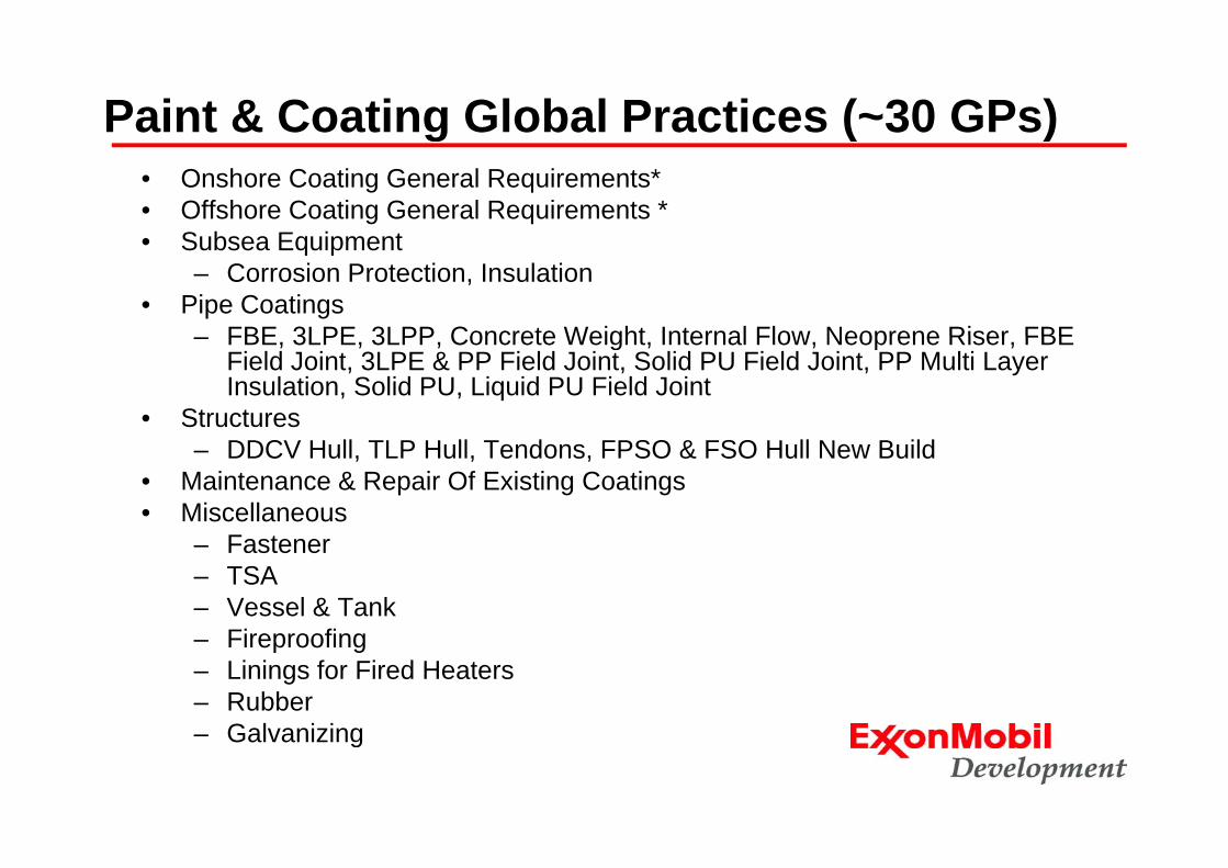
Paint & Coating Global Practices (~30 GPs)g ( )• Onshore Coating General Requirements*• Offshore Coating General Requirements *
• Maintenance & Repair Of Existing Coatings• Miscellaneous
– Fastener – TSA – Vessel & Tank
Fi fi– Fireproofing– Linings for Fired Heaters– Rubber
Galvanizing– Galvanizing
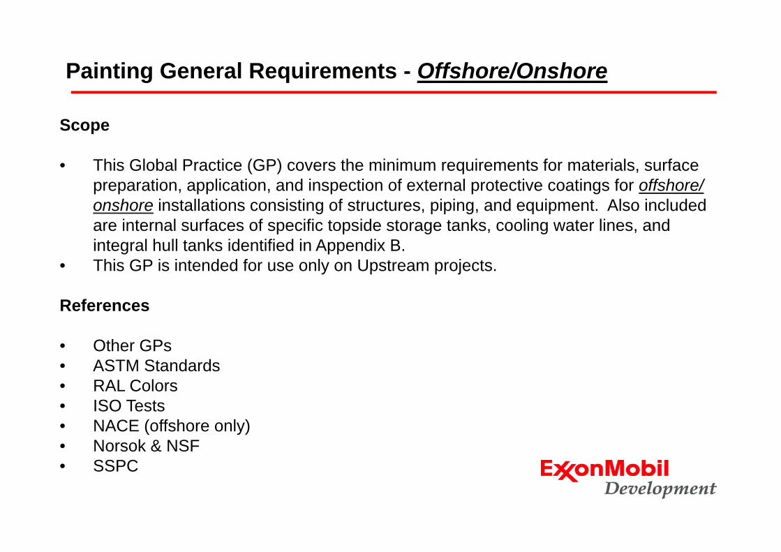
Painting General Requirements - Offshore/Onshore
Scope
• This Global Practice (GP) covers the minimum requirements for materials, surface preparation, application, and inspection of external protective coatings for offshore/ onshore installations consisting of structures, piping, and equipment. Also included g p p g q pare internal surfaces of specific topside storage tanks, cooling water lines, and integral hull tanks identified in Appendix B.
• This GP is intended for use only on Upstream projects.
References
• Other GPs• ASTM Standards• RAL Colors
ISO T t• ISO Tests• NACE (offshore only)• Norsok & NSF• SSPC• SSPC
Coating Work Process• All coating work performed in accordance with procurement documents, GP
and Contractor's approved procedures.• Normally, requires shop primed and field top coated for structural steel and y, q p p p
piping• Process equipment and machinery shop coated (prime and finish)• Before work commences, a pre-job conference or pre-production meeting
conducted to introduce contacts for Contractor and Company and theirconducted to introduce contacts for Contractor and Company and their project management and inspection representatives.
• Manufacturer's Standard Finishes• Items included in Contractor's Work ScopeItems included in Contractor s Work Scope
• Prepare surface and apply paint as per GP and procurement documents• Prepare and maintain inventory log • Repair procedures for each systemp p y• Waste disposal
• Items Not to be Coated• Surfaces such as concrete, glass sight glasses, thermometers, name g g g
tags, etc.• Safety and Environmental• Documentation
Coating Work Process• Qualification
– Written Coating Procedure (WCP)• Identification of the structures to be coated and not coated• Coating system and finish coat color to be applied• Specific coating products to be used for each coat • Data sheets and safety data sheets for each product• Personal protective equipment to be used• Personal protective equipment to be used• Coating material handling and storage and inventory controls• Salt contamination control• Surface preparation and additional preparation at welds and edges • Environmental controls• Scaffolding• Application, touch-up, and curing• Techniques to correct out of spec work• Techniques to correct out-of-spec work • Inspection• Disposal of waste, debris, and unconsumed coating materials.
– Coating Procedure Test (CPT) • Each system to be used, repair, application, curing and inspection
– Coating Applicator Qualification• ACQPA, NORSOK, FROSIO or other international organizations
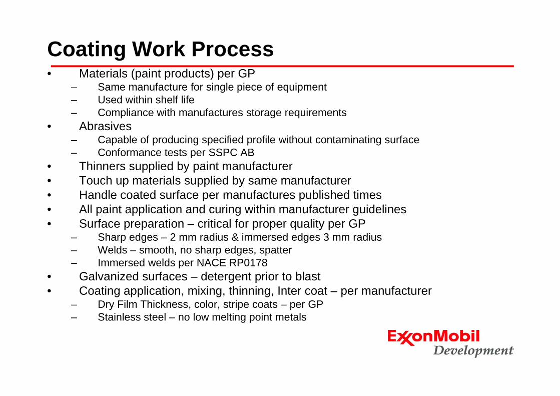
Coating Work Process• Materials (paint products) per GP
– Same manufacture for single piece of equipment– Used within shelf life– Compliance with manufactures storage requirements
• Abrasives– Capable of producing specified profile without contaminating surface– Conformance tests per SSPC AB– Conformance tests per SSPC AB
• Thinners supplied by paint manufacturer• Touch up materials supplied by same manufacturer• Handle coated surface per manufactures published timesHandle coated surface per manufactures published times• All paint application and curing within manufacturer guidelines• Surface preparation – critical for proper quality per GP
– Sharp edges – 2 mm radius & immersed edges 3 mm radius– Welds – smooth, no sharp edges, spatter– Immersed welds per NACE RP0178
• Galvanized surfaces – detergent prior to blastC ti li ti i i thi i I t t f t• Coating application, mixing, thinning, Inter coat – per manufacturer
– Dry Film Thickness, color, stripe coats – per GP– Stainless steel – no low melting point metals
Coating Work Process• Inspection and testing
– Contractor shall control quality to meet GP requirementsI t lifi d NSF NS 476 NACE th d tifi ti– Inspectors qualified NSF NS 476, NACE or other approved certification
– Contractor shall not initiate work until ITP activities prove acceptability– Inspection in ITP are hold points– Contractor shall supply test instruments with proper calibrations– Inspection documented on Company data sheet or approved equivalent– Upon work completion subject to final inspection and sign off– Remedial work
• Atmospheric, immersion, hot dipped galvanizing• Details in approved WCPpp
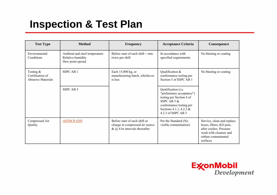
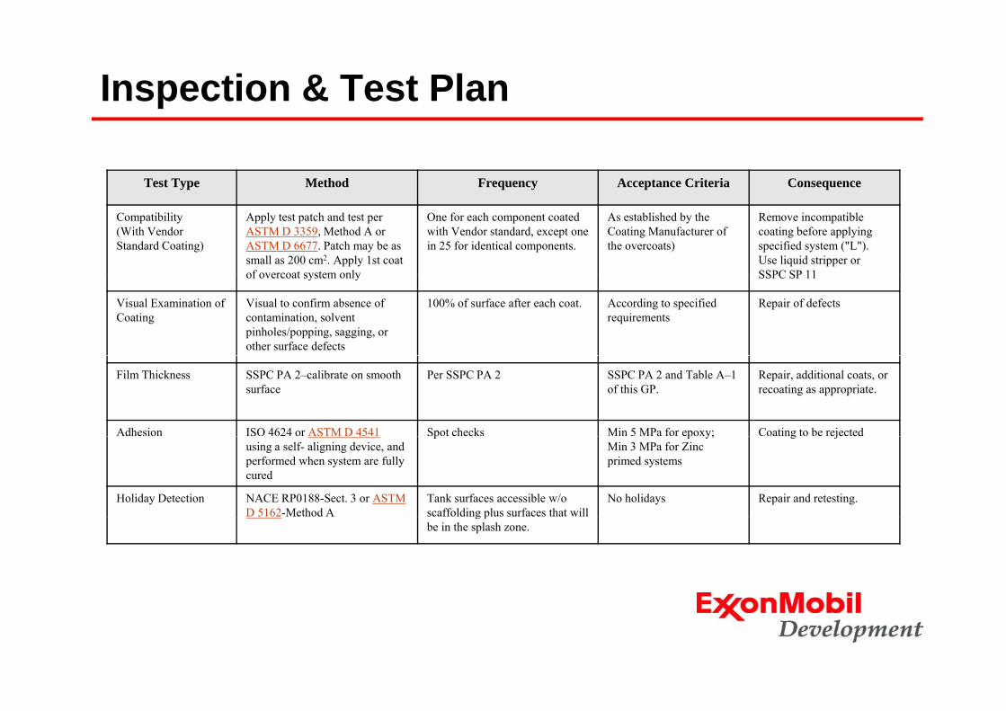
Inspection & Test PlanTest Type Method Frequency Acceptance Criteria Consequence
Environmental Ambient and steel temperature Before start of each shift + min In accordance with No blasting or coatingEnvironmental Conditions
Ambient and steel temperatureRelative humidityDew point spread
Before start of each shift + min twice per shift
In accordance with specified requirements
No blasting or coating
Testing & Certification of
SSPC AB 1 Each 15,000 kg, or manufacturing batch whichever
Qualification & conformance testing per
No blasting or coatingCertification of Abrasive Materials
manufacturing batch, whichever is less
conformance testing per Section 5 of SSPC AB 1
SSPC AB 3 Qualification (i.e. "preliminary acceptance") testing per Section 4 oftesting per Section 4 of SSPC AB 3 & conformance testing per Sections 4.1.1, 4.2.2 & 4.2.3 of SSPC AB 3
d i f f h hif h d d ( i l d lCompressed Air Quality
ASTM D 4285 Before start of each shift or change in compressed air source & @ 4 hr intervals thereafter
Per the Standard (No visible contamination)
Service, clean and replace hoses, filters, KO pots, after coolers. Pressure wash with cleanser and reblast contaminated surfaces
Inspection & Test PlanTest Type Method Frequency Acceptance Criteria Consequence
Visual Examination Visually, for sharp edges, weld spatter, slivers, rust grade, etc.
100% of all surfaces No defects, refer to specified requirements
Defects to be repaired
Surface Cleanliness a) Visualb) For dust
(a) SSPC VIS 1 or ISO 8501 (a) 100% visual of all surfaces (a) In accordance with specified requirements
(a) Re-blasting
(b) ISO 8502-3 (b) Spot checks, but not less than 1 per 10m².Specific location to be
(b) Max quantity and size rating 2
(b) Re-cleaning and retesting until acceptable
Specific location to be determined by Company inspector
Soluble Salts Extraction:ISO 8502-6 (Bresle)
(a) Immersion surfaces (includes underwater insulation):6 samples/2000 m2 of fabrication
(a) Average Conductivity corresponding to ≤ 20 mg/m2
Steam or clean water washing and retesting until entire
Assessment:ISO 8502-9 (Conductometric)
Or
6 samples/2000 m of fabricationSpecific location to be determined by Company inspector (1)
≤ 20 mg/m(2 μg/cm²) and Max conductivity corresponding to ≤ 30 mg/m2 water soluble salt's).
(b) Atmospheric Surfaces:4 samples/2000 m2 of fabricationSpecific location to be determined by Company Inspector (1)
(b) Average conductivity corresponding to ≤ 30 mg/ m2 and max conductivity corresponding to
40 / 2 l bl,
(Conductometric) ≤ 40 mg/ m2 water soluble salt's).
Inspection & Test Plan
Test Type Method Frequency Acceptance Criteria Consequence
Extent of Intercoat Cure Perform solvent rub test to ensure:
Perform 3 tests per 500 m² of surface to be coated
(a) Inorganic zinc is fully cured per ASTM D 4752 and
(a) Average resistance rating not less than 4
(a) Inadequately cured IZ:Take action to enhance level of cure (e.g., water misting). If ineffective, remove and reapply i d l d IZinadequately cured IZ.
(b) Epoxy for immersion, splash zone exposure, or under insulation is recoatable per ASTM D 5402. Unless
h i i d i i i
(b) Discoloration must be visible on the rub cloth, or…Thumbnail indentation at h f h b h
(b) Over cured Epoxy:Sweep blast using reduced nozzle pressure and fine abrasive
otherwise instructed, in writing, by the Coating Manufacturer, perform 50 double rubs using MEK.
the center of the rub path must be possible, orReduction in gloss must be visually discernable
Roughness Per ASTM D 4417 or ISO 8503
Each component, or once per 10 2
As specified Re-blasting, using coarser h d b i d/ISO 8503 m2 or harder abrasive and/or
more nozzle pressure.
Inspection & Test Plan
Test Type Method Frequency Acceptance Criteria Consequence
Compatibility(With Vendor Standard Coating)
Apply test patch and test per ASTM D 3359, Method A or ASTM D 6677. Patch may be as small as 200 cm2. Apply 1st coat of overcoat system only
One for each component coated with Vendor standard, except one in 25 for identical components.
As established by the Coating Manufacturer of the overcoats)
Remove incompatible coating before applying specified system ("L"). Use liquid stripper or SSPC SP 11of overcoat system only SSPC SP 11
Visual Examination of Coating
Visual to confirm absence of contamination, solvent pinholes/popping, sagging, or other surface defects
100% of surface after each coat. According to specified requirements
Repair of defects
Film Thickness SSPC PA 2–calibrate on smooth surface
Per SSPC PA 2 SSPC PA 2 and Table A–1 of this GP.
Repair, additional coats, or recoating as appropriate.
Adhesion ISO 4624 or ASTM D 4541 Spot checks Min 5 MPa for epoxy; Coating to be rejectedusing a self- aligning device, and performed when system are fully cured
p p y;Min 3 MPa for Zinc primed systems
g j
Holiday Detection NACE RP0188-Sect. 3 or ASTM D 5162-Method A
Tank surfaces accessible w/o scaffolding plus surfaces that will
No holidays Repair and retesting.g p
be in the splash zone.
Acceptable Paint Products - Onshore
Generic Product
DFT μm Min/Max SherwinProduct
Identifier Min/Max (ea coat) Carboline Hempel International Jotun
Sherwin Williams Sigma
Zinc Rich Epoxy
60–110 Carbozinc 859
17380 Interzinc 52 Barrier 90 Zinc Clad IV SigmaZinc 109
Epoxy Primer 70–120 Carboguard 888
15570 Intergard 251 or 400
Jotacote Universa or
Copoxy Shop Primer
SigmaPrime 200888 400 Universa or
Penguard HB Primer 200
NSF Epoxy 150–250 Carboguard 891
85671 Interseal 670HS (Buff/White)
Tankguard 412
Tank Clad HS
SigmaGuard CSF 585
3B Epoxy 130–165 Carbomastic 18 NT
17630/3 or 47741/3
Intershield 300 Jotacote Universal
SeaGuard 6000
SigmaPrime 200
Temperature Resistant Epoxy
75–125 Thermaline 450
85671 Intertherm 228 Tankguard Storage
Epo-Phen Sigma Phenguard 930
HB Epoxy 130–200 Carboguard 888
45880/1 or 45080/3
Intergard 475HS Penguard Midcoat
Macropoxy 646
SigmaCover 435
Urethane 40–75 134 or 134 HG
55210 or 55910
Interthane 990 or 990HS
Hardtop AS or Hardtop XP
Acrolon 218 HS
SigmaDur 550
Epoxy Mastic 100–200 Carbomastic 15
45880/1 Interseal 670HS Primastic Universal
Macropoxy 646
SigmaCover 630 (Alum.)
Sili 20 35 4700 5691 I t th 50 S l litt K Hi Si ThSilicone 20–35 4700 or 4700 VOC
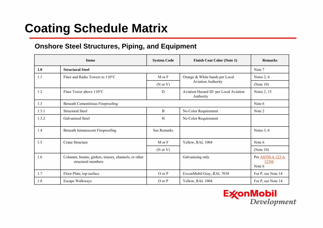
Items System Code Finish Coat Color (Note 1) Remarks
Onshore Steel Structures, Piping, and Equipment
y ( )
1.0 Structural Steel Note 7
1.1 Flare and Radio Towers to 110°C M or F Orange & White bands per Local Aviation Authority
Notes 2, 6
(N or V) (Note 10)
1.2 Flare Tower above 110°C D Aviation Hazard ID per Local Aviation Authority
Notes 2, 15
1.3 Beneath Cementitious Fireproofing Note 6
1.3.1 Structural Steel B No Color Requirement Note 2
1.3.2 Galvanized Steel H No Color Requirement
1.4 Beneath Intumescent Fireproofing See Remarks Notes 3, 6
1.5 Crane Structure M or F Yellow, RAL 1004 Note 6
(N or V) (Note 10)
1.6 Columns, beams, girders, trusses, channels, or other structural members
Galvanizing only Per ASTM A 123/A 123M
Note 6Note 6
1.7 Floor Plate, top surface O or P ExxonMobil Gray, RAL 7038 For P, see Note 14
1.8 Escape Walkways O or P Yellow, RAL 1004 For P, see Note 14
Coating Schedule Matrix
Items System Code Finish Coat Color (Note 1) Remarks
Offshore Steel Structures, Piping, and Equipment
1.0 Structural Steel–Topside Surfaces Above Splash Zone Note 7
1.1 Flare boom and Radio Towers to 110°C A or C Aviation Hazard ID per Local Aviation Authority Notes 3 & 6
1.2 Flare boom above 110°C D Aviation Hazard ID per Local Aviation Authority Notes 3 & 15
1.3 Heliport Surfaces R Yellow, RAL 1004–with Black, RAL 9017, and White, RAL 9002 Urethane markings. See GP 25-01-13.
See Note 14 for broadcast type non-skid
1.4 Crane structure A or C Yellow, RAL 1004 Note 6
1.5 Columns, beams, girders, trusses, channels, bulkheads, deck bottoms, or other structural members
A or C ExxonMobil Gray, RAL 7038 Notes 2, 3, 6
1.6 Deck, top surface O or P ExxonMobil Gray, RAL 7038 For P, see Note 1414
1.8 Laydown decks Q ExxonMobil Gray, RAL 7038
1.9 Assembled galvanized structures, including bolts
H ExxonMobil Gray, RAL 7038 Notes 2, 6
1.11 Galvanized deck plate and ladder rungs S ExxonMobil Gray, RAL 7038
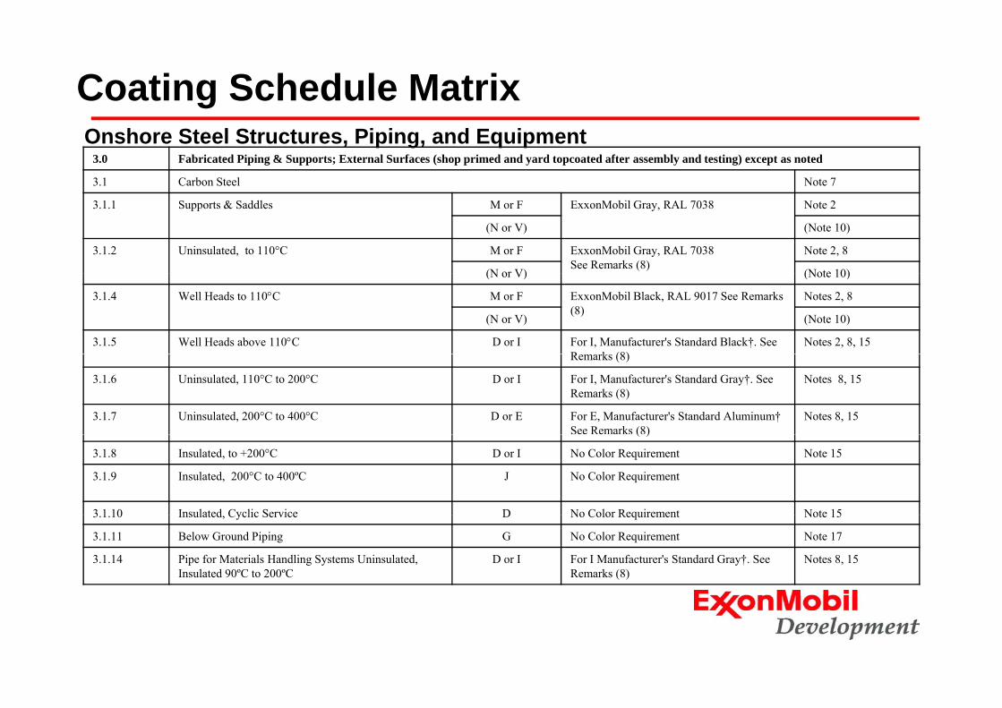
Coating Schedule Matrix3.0 Fabricated Piping & Supports; External Surfaces (shop primed and yard topcoated after assembly and testing) except as noted
3.1 Carbon Steel Note 7
Onshore Steel Structures, Piping, and Equipment
3.1.1 Supports & Saddles M or F ExxonMobil Gray, RAL 7038 Note 2
(N or V) (Note 10)
3.1.2 Uninsulated, to 110°C M or F ExxonMobil Gray, RAL 7038See Remarks (8)
Note 2, 8
(N or V) (Note 10)(N or V) (Note 10)
3.1.4 Well Heads to 110°C M or F ExxonMobil Black, RAL 9017 See Remarks (8)
Notes 2, 8
(N or V) (Note 10)
3.1.5 Well Heads above 110°C D or I For I, Manufacturer's Standard Black†. See R k (8)
Notes 2, 8, 15Remarks (8)
3.1.6 Uninsulated, 110°C to 200°C D or I For I, Manufacturer's Standard Gray†. See Remarks (8)
Notes 8, 15
3.1.7 Uninsulated, 200°C to 400°C D or E For E, Manufacturer's Standard Aluminum† See Remarks (8)
Notes 8, 15( )
3.1.8 Insulated, to +200°C D or I No Color Requirement Note 15
3.1.9 Insulated, 200°C to 400ºC J No Color Requirement
3 1 10 Insulated Cyclic Service D No Color Requirement Note 153.1.10 Insulated, Cyclic Service D No Color Requirement Note 15
3.1.11 Below Ground Piping G No Color Requirement Note 17
3.1.14 Pipe for Materials Handling Systems Uninsulated, Insulated 90ºC to 200ºC
D or I For I Manufacturer's Standard Gray†. See Remarks (8)
Notes 8, 15
Coating Schedule Matrix
4.0 Vessels and Heat Exchangers; External Surfaces (shop primed and topcoated after assembly and testing)
Onshore Steel Structures, Piping, and Equipment
4.1 Carbon Steel Notes 7, 23
4.1.1 Uninsulated, to 110°C, Including Supports & Skirts M or F ExxonMobil Gray, RAL 7038See Remarks (8)
Notes 2, 4, 8
(N or V) (Note 10)
4 1 2 Uninsulated 110°C to 200°C D or I For I Manufacturer's Standard Gray† See Notes 2 4 8 154.1.2 Uninsulated, 110 C to 200 C D or I For I, Manufacturer s Standard Gray† See Remarks (8)
Notes 2, 4, 8, 15
4.1.3 Uninsulated, 200°C to 400°C D or E For E, Manufacturer's Standard Aluminum†
See Remarks (8)
Notes 2, 4, 8, 15
4.1.4 Insulated D No Color Requirement Notes 4, 15
4.2 Stainless Steel Notes 4, 7, 10, 16
4.2.1 Uninsulated: Austenitic to 65°C,
Duplex to 110 ºC
I Manufacturer's Standard Gray†. See Remarks (8)
Notes 2, 8
Duplex to 110 ºC, Super Duplex to 120 ºC and Super Austenitic to 130 ºC
4.2.2 Insulated:Austenitic to 65°C,
Duplex to 110 ºC
I No Color Requirements
Duplex to 110 ºC,Super Duplex to 120 ºC,and Super Austenitic to 130 ºC
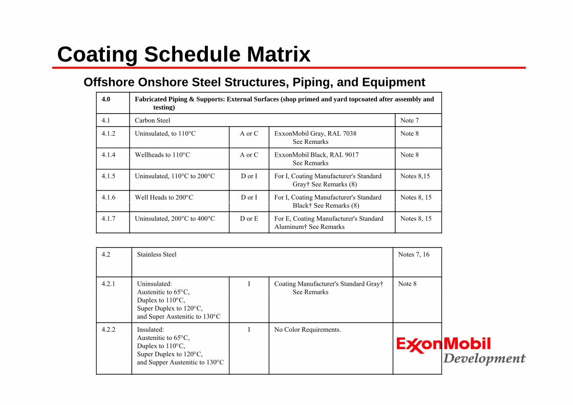
Coating Schedule Matrix
4.0 Fabricated Piping & Supports: External Surfaces (shop primed and yard topcoated after assembly and testing)
gOffshore Onshore Steel Structures, Piping, and Equipment
g)
4.1 Carbon Steel Note 7
4.1.2 Uninsulated, to 110°C A or C ExxonMobil Gray, RAL 7038See Remarks
Note 8
4.1.4 Wellheads to 110°C A or C ExxonMobil Black, RAL 9017 Note 84.1.4 Wellheads to 110 C A or C ExxonMobil Black, RAL 9017See Remarks
Note 8
4.1.5 Uninsulated, 110°C to 200°C D or I For I, Coating Manufacturer's Standard Gray† See Remarks (8)
Notes 8,15
4.1.6 Well Heads to 200°C D or I For I, Coating Manufacturer's Standard Notes 8, 15Black† See Remarks (8)
4.1.7 Uninsulated, 200°C to 400°C D or E For E, Coating Manufacturer's Standard Aluminum† See Remarks
Notes 8, 15
4.2 Stainless Steel Notes 7, 16
4.2.1 Uninsulated:Austenitic to 65°C,
I Coating Manufacturer's Standard Gray†See Remarks
Note 8,
Duplex to 110°C,Super Duplex to 120°C,and Super Austenitic to 130°C
4.2.2 Insulated:Austenitic to 65°C,
I No Color Requirements.,
Duplex to 110°C,Super Duplex to 120°C,and Supper Austenitic to 130°C
Coating Schedule Matrix
8.0 Tanks Note 21
8 1 Carbon Steel External Surfaces Note 7
gOnshore Steel Structures, Piping, and Equipment
8.1 Carbon Steel External Surfaces Note 7
8.1.1 Uninsulated: Nonvolatile Products M or F ExxonMobil Gray, RAL 7038See Remarks (8)
Notes 2, 8, 9, 20
(N or V) (Note 10)
8.1.2 Uninsulated: Volatile Products M or F ExxonMobil White, RAL 9002 See R k (8)
Notes 2, 8, 9, 20Remarks (8)
(N or V) (Note 10)
8.1.3 Insulated, to 200°C I or D For I Manufacturer's Standard Gray† Note 15
8.1.4 Insulated, 200°C to 400ºC J No Color Requirement
8.1.5 Insulated-Cyclic Service D No Color Requirement Note 15
8.1.7 For Materials Handling Systems: Uninsulated & Insulated 90ºC
to 200 ºC
D or I For I –uninsulated, Manufacturer's Standard Alum† No color requirement for all other
Coating Schedule/Matrix for Offshore / Onshore Steel Structures, Piping, and Equipment
• Structural Steel• In-Water/Over-Water Structures / Splash / SubmergedIn Water/Over Water Structures / Splash / Submerged• Fabricated Piping & Supports; External Surfaces • Vessels and Heat Exchangers; External Surfaces• Pumps Compressors and Rotating Equipment; External Surfaces• Pumps, Compressors, and Rotating Equipment; External Surfaces• Electric Motors and Equipment• Instrument and Control Panels
T k• Tanks• Furnaces, Stacks, Breaching, Ducts, and Boilers; External Surfaces
(Carbon Steel)Skid t d E i t• Skid-mounted Equipment
• Living Modules• Subsea Equipment
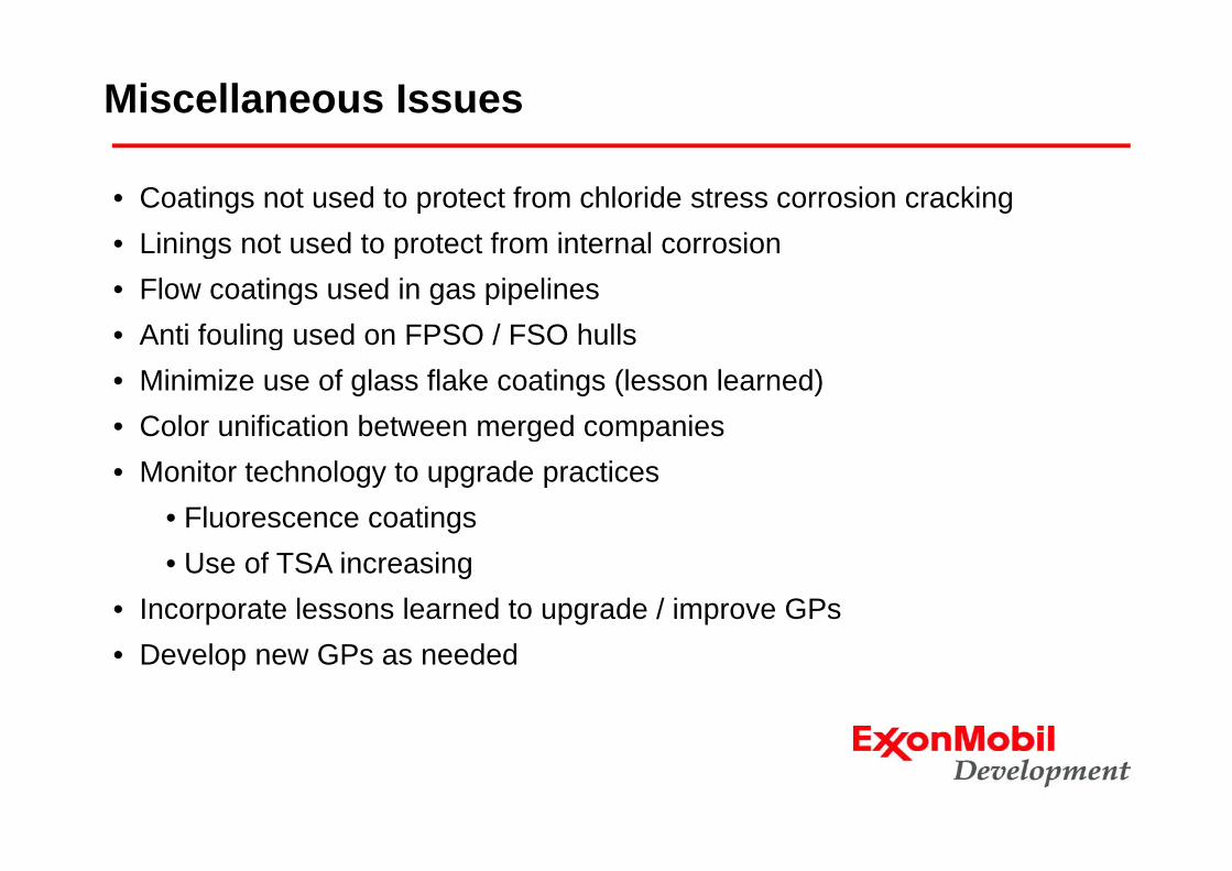
Miscellaneous Issues
• Coatings not used to protect from chloride stress corrosion crackingLinings not sed to protect from internal corrosion• Linings not used to protect from internal corrosion
• Flow coatings used in gas pipelines• Anti fouling used on FPSO / FSO hulls• Anti fouling used on FPSO / FSO hulls• Minimize use of glass flake coatings (lesson learned)• Color unification between merged companiesColor unification between merged companies• Monitor technology to upgrade practices
• Fluorescence coatings• Use of TSA increasing
• Incorporate lessons learned to upgrade / improve GPs• Develop new GPs as needed
Pipe Coatings – Various GPsScope• Global Practice (GP) covers the selection of external coatings for
onshore and offshore carbon steel pipelines This GP shall be used inonshore and offshore carbon steel pipelines. This GP shall be used in conjunction with the specific GP that covers the selected pipe coating and field joint coating.
References• Other GPs• ASTM • NACE• ISO• API
AFNOR• AFNOR• CSA
SpecificsSpecifics• FBE, 3LPE, 3LPP, Internal Flow, Neoprene Riser, Field Joints• Only approved products, thickness and systems
PPM & PQT i d• PPM & PQT required• Detailed ITP
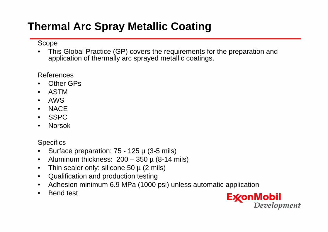
Thermal Arc Spray Metallic CoatingScope • This Global Practice (GP) covers the requirements for the preparation and
application of thermally arc sprayed metallic coatings.
Fluoropolymer Coatings for FastenersScope •Fasteners coated in accordance with this Global Practice (GP) are intended for use in assembly of piping flanges and include studs, bolts, nuts, and washers for systems y p p g g , , , yoperating at temperatures below 180°C (350°F). This GP is not intended for use with subsea equipment or for fasteners that may experience operating temperatures in excess of 180°C (350°F).
References•ASTM •ASMEASME•API•SSPC
Specifics•Two approved coating systems with specific products: onshore & offshore•Basecoat, which provides the corrosion resistancep•Fluoropolymer topcoat, which is intended to reduce torque-up friction•Qualification by performance based on salt spray •Fastener suppliers help develop GP