1 Eye Monitored Wheel Chair Control for people suffering from Quadriplegia A Design Project Report Presented to the School of Electrical and Computer Engineering of Cornell University In Partial Fulfillment of the Requirements for the Degree of Master of Engineering, Electrical and Computer Engineering Submitted by Ankur Thakkar (akt52) Darshan Shah (drs364) MEng Field Advisor: Bruce Robert Land Degree Date May 2014 Final MEng Project
Transcript
1
Eye Monitored Wheel Chair Control for people suffering from
Quadriplegia
A Design Project Report
Presented to the School of Electrical and Computer Engineering of
Cornell University
In Partial Fulfillment of the Requirements for the Degree of
Master of Engineering, Electrical and Computer Engineering
Submitted by
Ankur Thakkar (akt52)
Darshan Shah (drs364)
MEng Field Advisor: Bruce Robert Land
Degree Date May 2014 Final MEng Project
2
Master of Engineering Program
School of Electrical and Computer Engineering
Cornell University
Design Project Report
Abstract -
Statistics suggests that there are 11,000 new cases of quadriplegia every year in United States of
America. Great people like Stephen Hawking and Max Brito have been suffering from this
crippling phenomenon. Our project is an attempt to make lives of the people suffering from this
phenomenon simple and by simpler we mean self-reliant, which will thereby reinstate their
confidence and their happiness. The idea is to create an Eye Monitored System which allows
movement of the patient’s wheelchair depending on the eye movements. We know that a person
suffering from quadriplegia can partially move his eyes and tilt his head, thus presenting an
opportunity for detecting those movements. We have created a device where a patient sitting on
the Wheel Chair assembly looking directly at the camera, is able to move in a direction just by
looking in that direction. The camera signals are monitored by a MATLAB script, which will
then guide the motors wired to the AtMega1284P Microcontroller over the Serial Interface to
move in a particular direction. The system is cost effective and thus can be used by patients
spread over a large economy range.
3
Executive Summary -
For our MEng. Design Project, we wanted to utilize the opportunity to design something which
could be a contribution in our own small way to the society. Quadriplegia is paralysis caused by
illness or injury to the humans that results in partial or complete loss of limbs and torso. Its a
phenomenon which confines the ability of a person to move by himself, and he has to rely on
someone to carry him around.
Researchers suggest that this leads to a drop in the self-reliance of these people. We realized that
technology can intervene and help reinstate confidence of people suffering from Quadriplegia,
by creating a medium, through which they can move at will. The complexity lies in the fact that
they may be able to move only their eyes and partially their head.
We precisely aim at targeting the movements of the eye and the head. The idea is to create a eye
monitored wheelchair system where a camera constantly stares at the person’s eyes and based on
the combined movement of eye and head, decide to move the wheelchair in the direction the
person desires to move in.
The camera is wired to the person’s laptop which has a MATLAB script running which
constantly captures snapshots and processes them. The script based on the processing determines
whether the person wants to move in a particular direction, and communicates this information
using serial communication to a microcontroller which drives motors of the wheelchair is the
desired direction.
The existing systems in the market use a cheek or tongue monitored systems, where some body
part of the person is wired to some electrical circuitry. But, it is very annoying for a person to
have something wired to his body all the time. The novelty of our system lies in the fact that no
part of the system physically interacts with the user, making him feel comfortable.
4
Table of Contents –
1. Introduction 5
1.1 Problem Statement 6
1.2 Range of Solutions 6
1.3 Product Design Overview 6
2. High Level Design 8
2.1 Eye Detection and Motion Tracking 8
2.2 AtMega1284P Controlled Motor Assembly 8
3. Software Design 11
3.1 MATLAB Component 11
3.2 Firmware Design 15
4. Hardware Design 16
4.1 Motor Circuit 16
5. Mechanical Design 18
6. Testing and Results 20
6.1 Testing Strategy 20
6.2 Speed of Execution 21
6.3 Accuracy 21
6.4 Safety Features 22
7. Conclusions 23
7.1 Performance 23
7.2 Future Modifications 23
Appendix A – User Manual 24
Appendix B – MATLAB Script 25
Acknowledgements 33
References 34
5
1. Introduction
The number of persons who are paralyzed and therefore dependent on others due to loss of self-
mobility is growing with the population. The development of the wheelchair for paralyzed users
is surprisingly recent starting with the conventional manually powered wheelchairs and
advancing to electrical wheelchairs. Conventional wheelchair use tends to focus exclusively on
manual use which use which assumes users still able to use their hands which excludes those
unable to do so. Diseases or accidents injuring the nervous system also frequently because
people lose their ability to move their voluntary muscle. Because voluntary muscle is the main
actuator enabling people to move their body, paralysis may cause a person not move their
locomotor organ such as arm, leg and others. Paralysis may be local, global, or follow specific
patterns. Most paralysis are constant, however there are other forms such as periodic paralysis
(caused by genetic diseases), caused by various other factors.
Scientist Stephen W. Hawking is perhaps the most well-known victim of major paralysis –
Hawking was diagnosed with incurable Amyotrophic Lateral Sclerosis (ALS) in 1962, thereafter
using a wheelchair to move. Many of those suffering close to or complete paralysis usually
however still can control their eye movement which inspired us to develop an eye-controlled
electric wheelchair.
The idea of an eye-monitored wheelchair was inspired by a past project of one of the group
members, Ankur Thakkar, where he had created a glove based wheel chair. In that project, the
finger movements of the handicapped person were used to guide the wheel chair in the desired
direction. He wanted to take the idea forward by making the system completely isolated from the
person physically, and extend the usability of the system to a person suffering from quadriplegia.
6
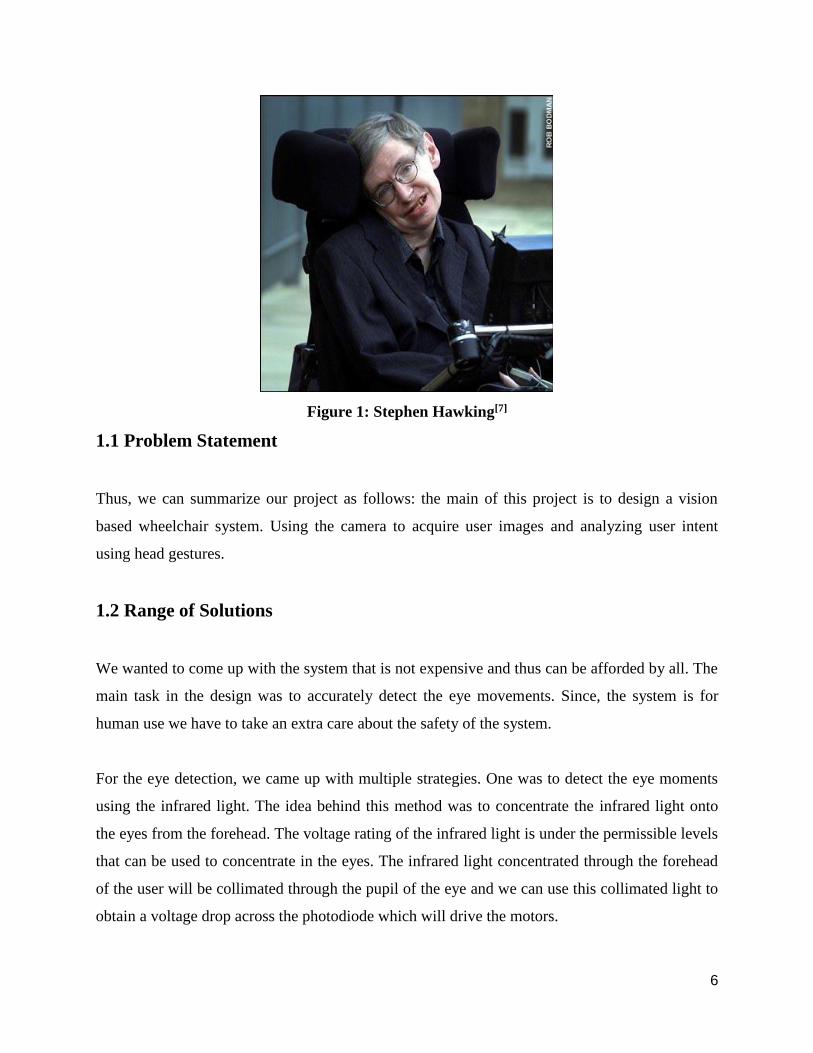
Figure 1: Stephen Hawking[7]
1.1 Problem Statement
Thus, we can summarize our project as follows: the main of this project is to design a vision
based wheelchair system. Using the camera to acquire user images and analyzing user intent
using head gestures.
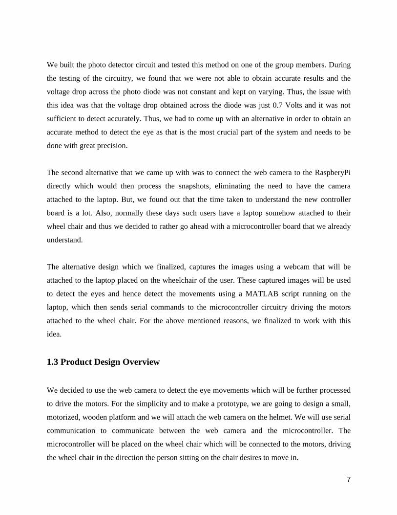
1.2 Range of Solutions
We wanted to come up with the system that is not expensive and thus can be afforded by all. The
main task in the design was to accurately detect the eye movements. Since, the system is for
human use we have to take an extra care about the safety of the system.
For the eye detection, we came up with multiple strategies. One was to detect the eye moments
using the infrared light. The idea behind this method was to concentrate the infrared light onto
the eyes from the forehead. The voltage rating of the infrared light is under the permissible levels
that can be used to concentrate in the eyes. The infrared light concentrated through the forehead
of the user will be collimated through the pupil of the eye and we can use this collimated light to
obtain a voltage drop across the photodiode which will drive the motors.
7
We built the photo detector circuit and tested this method on one of the group members. During
the testing of the circuitry, we found that we were not able to obtain accurate results and the
voltage drop across the photo diode was not constant and kept on varying. Thus, the issue with
this idea was that the voltage drop obtained across the diode was just 0.7 Volts and it was not
sufficient to detect accurately. Thus, we had to come up with an alternative in order to obtain an
accurate method to detect the eye as that is the most crucial part of the system and needs to be
done with great precision.
The second alternative that we came up with was to connect the web camera to the RaspberyPi
directly which would then process the snapshots, eliminating the need to have the camera
attached to the laptop. But, we found out that the time taken to understand the new controller
board is a lot. Also, normally these days such users have a laptop somehow attached to their
wheel chair and thus we decided to rather go ahead with a microcontroller board that we already
understand.
The alternative design which we finalized, captures the images using a webcam that will be
attached to the laptop placed on the wheelchair of the user. These captured images will be used
to detect the eyes and hence detect the movements using a MATLAB script running on the
laptop, which then sends serial commands to the microcontroller circuitry driving the motors
attached to the wheel chair. For the above mentioned reasons, we finalized to work with this
idea.
1.3 Product Design Overview
We decided to use the web camera to detect the eye movements which will be further processed
to drive the motors. For the simplicity and to make a prototype, we are going to design a small,
motorized, wooden platform and we will attach the web camera on the helmet. We will use serial
communication to communicate between the web camera and the microcontroller. The
microcontroller will be placed on the wheel chair which will be connected to the motors, driving
the wheel chair in the direction the person sitting on the chair desires to move in.
8
2. High Level Design
There are two major components from the system design standpoint -
a) Eye-Detection and motion tracking.
b) ATMega1284P controlled Wheel Chair Assembly.
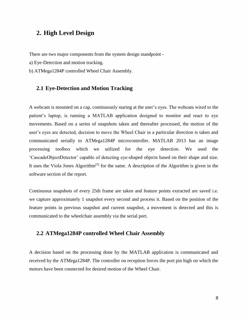
2.1 Eye-Detection and Motion Tracking
A webcam is mounted on a cap, continuously staring at the user’s eyes. The webcam wired to the
patient’s laptop, is running a MATLAB application designed to monitor and react to eye
movements. Based on a series of snapshots taken and thereafter processed, the motion of the
user’s eyes are detected, decision to move the Wheel Chair in a particular direction is taken and
communicated serially to ATMega1284P microcontroller. MATLAB 2013 has an image
processing toolbox which we utilized for the eye detection. We used the
‘CascadeObjectDetector’ capable of detecting eye-shaped objects based on their shape and size.
It uses the Viola Jones Algorithm[5] for the same. A description of the Algorithm is given in the
software section of the report.
Continuous snapshots of every 25th frame are taken and feature points extracted are saved i.e.
we capture approximately 1 snapshot every second and process it. Based on the position of the
feature points in previous snapshot and current snapshot, a movement is detected and this is
communicated to the wheelchair assembly via the serial port.
2.2 ATMega1284P controlled Wheel Chair Assembly
A decision based on the processing done by the MATLAB application is communicated and
received by the ATMega1284P. The controller on reception forces the port pin high on which the
motors have been connected for desired motion of the Wheel Chair.
9
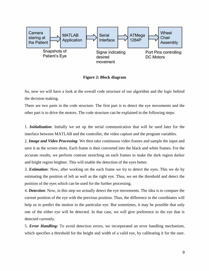
Figure 2: Block diagram
So, now we will have a look at the overall code structure of our algorithm and the logic behind
the decision making.
There are two parts in the code structure. The first part is to detect the eye movements and the
other part is to drive the motors. The code structure can be explained in the following steps:
1. Initialization: Initially we set up the serial communication that will be used later for the
interface between MATLAB and the controller, the video capture and the program variables.
2. Image and Video Processing: We then take continuous video frames and sample the input and
save it as the screen shots. Each frame is then converted into the black and white frames. For the
accurate results, we perform contrast stretching on each frames to make the dark region darker
and bright region brighter. This will enable the detection of the eyes better.
3. Estimation: Now, after working on the each frame we try to detect the eyes. This we do by
estimating the position of left as well as the right eye. Thus, we set the threshold and detect the
position of the eyes which can be used for the further processing.
4. Detection: Now, in this step we actually detect the eye movements. The idea is to compare the
current position of the eye with the previous position. Thus, the difference in the coordinates will
help us to predict the motion in the particular eye. But sometimes, it may be possible that only
one of the either eye will be detected. In that case, we will give preference to the eye that is
detected currently.
5. Error Handling: To avoid detection errors, we incorporated an error handling mechanism,
which specifies a threshold for the height and width of a valid eye, by calibrating it for the user.
10
If the detection results give a height and width value lesser or greater than the threshold, the
value is voided and not considered for the decision making.
6. Motion: Now after detecting the eye movements, we have to come up with a decision
algorithm that will help the controller to drive the motors accordingly:
a. Valid Left: The decision to turn left will be considered as valid if the eye turns left and stays
there for a cycle. This action will be detected as a left turn request. After that, the patient will
turn right to again look forward. Thus, this signal should be considered as void.
b. Valid Right: Similarly, the decision to turn right will be considered as valid if the eye turns
right and stays there for a cycle. This action will be detected as a right turn request. After that,
the patient will turn left to again look forward. Thus, this signal should be considered as void.
c. Valid Straight: The signal to go straight is when a person looks left and right or right and then
left. This will be detected as to go straight.
7. Safety Considerations: Given the application of the system, we incorporated a safety
mechanism, wherein based on the blink detection the wheel chair halts. If the user wants to halt
the wheel chair in case of an emergency, he can blink thrice, causing the wheel chair to halt.
8. Serial Communication: Now according to the detected command, the MATLAB application
will transmit 0, 1 or 2 for left, right and straight respectively to the controller which will drive the
motors.
11
3. Software Design
There are multiple aspects to the software design of this project. Since majority of computational
work is done in software, a lot of our time went in software design and testing.
The MATLAB component is responsible for capture of regular snapshots, processing of those
snapshots, determining the movement of eyes, algorithm for movement of wheelchair and serial
transmission of the decision to move.
The firmware component deals with receiving the serial signal, based on which drive the motor
connected to the port pins, forcing the wheelchair in the direction it is supposed to move in.
3.1 MATLAB Component
The MATLAB design can be structured into many small sub-parts each of which is described
below -
(i) Initialization of variables and setting up serial communication -
MATLAB 2013 can easily be configured to serially transmitting data on the Port mentioned in
the code. Initially all the already set up serial ports are disabled. After which, we need to mention
the current port, by checking the ‘Device Manager’ which indicates the port in use. The baud rate
of communication is set to 9600. The communication is set to have no flow control and parity
check is disabled.
After setting up the serial communication to enable the data link between MATLAB and
AtMega1284P, we reset the variables needed in the course of the program to their initial
valuables.
12
(ii) Image Capture and Eye Detection -
MATLAB 2013 equips an Image Processing Toolbox, which we have used majorly in this
section of the Software Design. We use a Microsoft LifeCam HD-5000 web camera which is
connected via a USB cable to the Computer on which the MATLAB script is running. We can
stream continuous video signals on MATLAB coming from the camera using the video
processing toolbox available. The function ‘imaqhwinfo’ is used to recognize all video capture
adaptors. Identifying the correct device and then using it to stream the video signal is the next
step.
The requirement of our design was to continuously look at different frames, based on which
determine motion. It is practically impossible to do a lot of processing on a per frame basis. That
is why we try to sample every 25th frame. So, a snapshot of every 25th frame is captured and
processed. We used the ‘getsnapshot’ command to capture these snapshots.
The image is then converted to grayscale image, as we do not need color information to detect
eye feature points. The conversion infact makes the detection easier. The ‘imadjust’ command is
used then to contrast stretch the image to make darker sections even darker, enhancing the eye
feature points useful for the application.
This pre-processing of the image makes the image easier to process and extract the eyes from.
After the initial pre-processing, we move towards the eye detection. The Eye Detection is done
using the Viola-Jones Object Detection Algorithm. Primarily this algorithm was designated for
face detection though it is used for all sorts of object detections. The algorithm is designed to
work on sum of pixels in a rectangular area. Viola-Jones algorithm[5] says that face can be
detected by looking for rectangle. And then the large rectangle is made up of many such smaller
rectangles, which are fundamentally feature points on a human face.
13
The ‘cascadeobjectdetector’[6] on MATLAB, utilized this algorithm to extract and detect the eyes
of the person. We then show the detected eye by plotting the rectangle at the appropriate position
of the eye.
(iii) Image Processing -
Initially, all we do is monitor if any eye feature points have been detected or not. If not set a flag
and display it on the debug screen. To increase the detection accuracy, we wanted to neglect all
other points on the screen except the actual eye of the person. The reason being, if anyone except
quadriplegic person comes in front of the camera, the person should not affect the system. Also
certain things seemingly looking like eyes should be rejected as well. The way we incorporated
this is taking into account the height and length of the eye. After repeated testing, we decide a
length and height of a valid eye, sets a range around the threshold and reject everything which is
outside it.
The blink detection section is not compute intensive. We use a flag which is set each time no
valid eyes are detected. If in corresponding frames the flag value sets, it indicates a blink. A
series of 3 such blinks command the motors to freeze, halting the wheel chair.
What is assumed is that the position of the camera is fixed, relative to which the left and the right
eye approximate positions can be estimated. Using this, we try to distinguish and store left and
right eyes in different matrices. This helps getting a clear discrimination between both the eyes,
helping in easy movement detection.
(iv) Movement Detection -
The movement detection is done with a very basic principle. We take in the feature points for
both left and right eyes and save it. Thereafter take the difference in pixels of the left eye
position and right eye position in the current snapshot from the previous snapshot. We define the
threshold for the minimum movement of the eye required to be qualified as a valid attempt. In
each snapshot the difference is evaluated, and if this difference above the threshold in any
14
direction left or right, the flags indicating left movement or right movement are set. If the
difference is not above the threshold, the flag which says that no movement has occurred is set.
Figure 3: Eye detection
Sometimes due to non-linearities, both the eyes are not detected. At such instances while
evaluating the difference for detecting movement, we would give a bias to the eye which was
detected in the previous snapshot.
After detecting the eye movements, we can proceed to determining and sending serial signals to
the micro-controller.
15
(v) Motor signals -
The way we qualify a valid right, left and straight attempts to move, we need to incorporate
many factors. The way a valid right is recognized is by tilting face on the right side and stay
there for a second, after which the wheel chair starts moving. But the person’s face is still tilted
on the right. If the person now tries to go back to the initial position by tilting left, the system
will detect it and lead to an otherwise invalid left movement of the chair. This has to be avoided.
We set flags for left and right movements each time the wheel chair moves, avoiding precisely
this unwarranted behavior of the system. The way a valid straight movement is detected is titling
in corresponding frames in left and right directions. Over here as well, the effect of the offset
coming into picture are avoided in the same fashion with the help of flags.
As already mentioned, three corresponding blinks should halt the motors. Along with the motion
command, a halt command is also transmitted to the microcontroller assembly which thereby
halts the motors as per the user’s desire.
After determining which direction the wheel chair has to be moved in, the decision is transmitted
to the micro-controller via the serial port. The only thing sent is a one digit decision, saying right,
left or straight movement.
3.2 Firmware Design
The firmware design is fairly straight forward as all the computation has been done on
MATLAB and the only thing which the micro-controller has to do is control the motors to move
in a particular direction.
The firmware constantly monitoring the serial input. The firmware turns ON the port pin based
on this received signal. After turning ON the port pin, a small delay is given, giving the chair
time to move for a fixed time in the desired direction.
16
As far as the firmware design is concerned, it is fairly simple. All that is required is take in the
serial input, move in a direction, give a delay and keep doing this repeatedly.
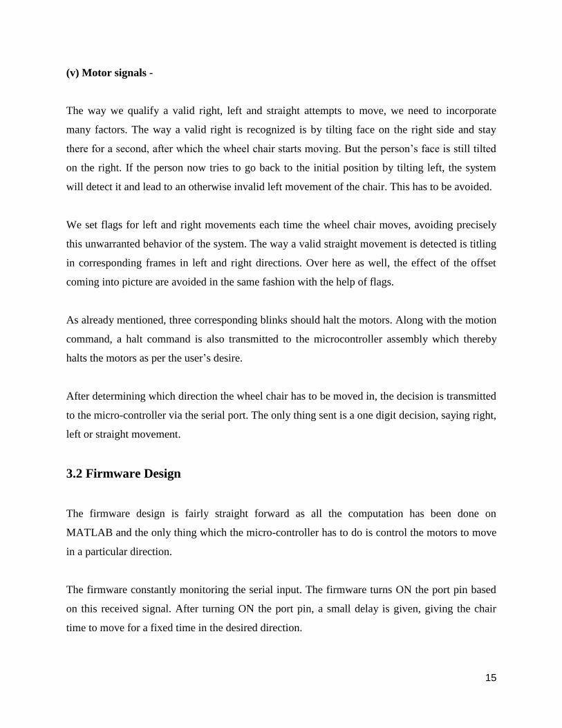
4. Hardware Design
The hardware part consists only to control the motor. The motor controller circuit is given below.
Figure 4: Motor control circuit
4.1 Motor Control
The signal that we obtain from the MATLAB script, we then use that to drive the motors. The
MATLAB program does all the decision making for the motor to run in which direction. So, the
script sends the bit 0,1 and 2 for left, right and straight direction. The circuit shown below is
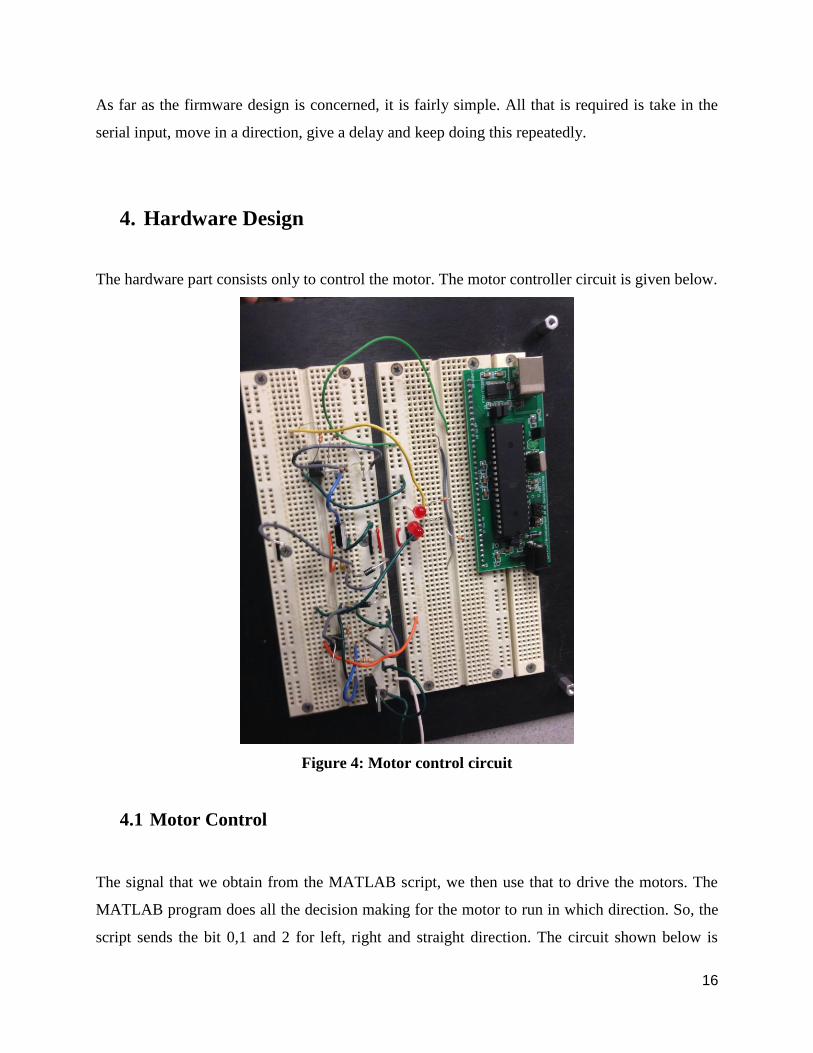
17
fairly safe and used to drive the motors. An optoisolator completely isolates the microcontroller
from the motor. The diode placed across the motor shorts out spikes when the motor is turned
off. The resistor grounding the base of the phototransistor is set for best fall time, probably
around 1Mohm. The motor capacitor should start around 0.1uf. The pinout of the 4N35
optoisolator and BUZ73 are also shown. Note that the bandwidth of the 4N35 is very small, so
we use a low PWM frequency, perhaps about 1000 Hz.
Figure 5: Circuit diagram[4]
18
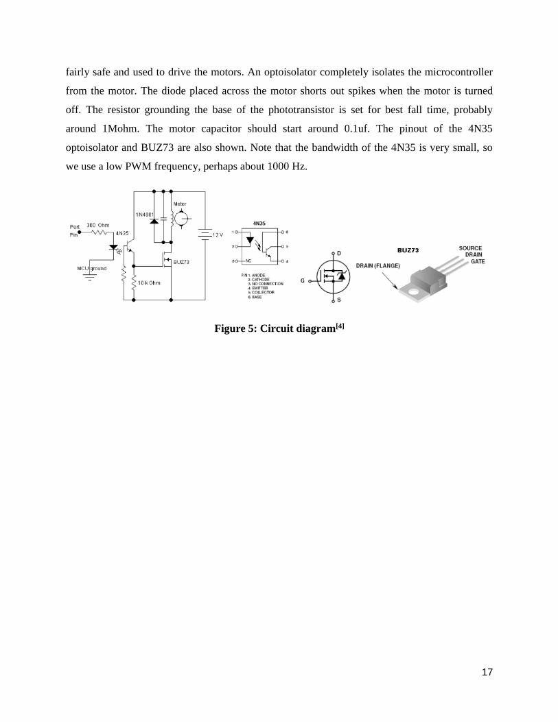
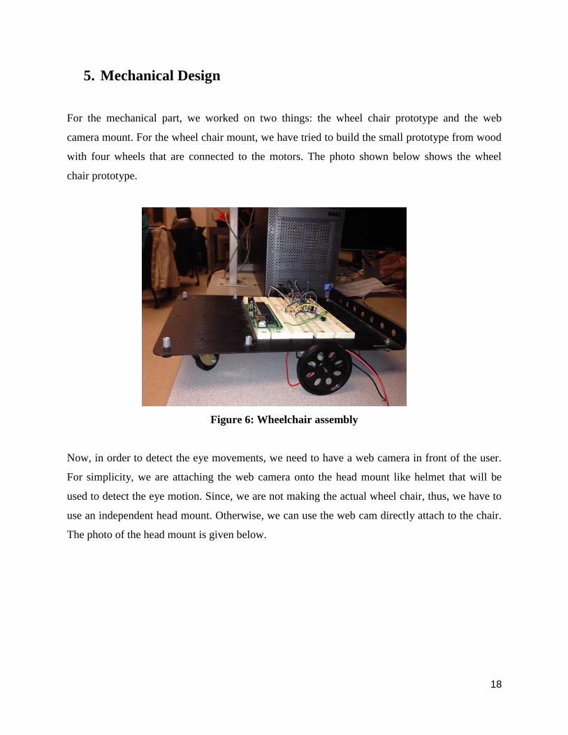
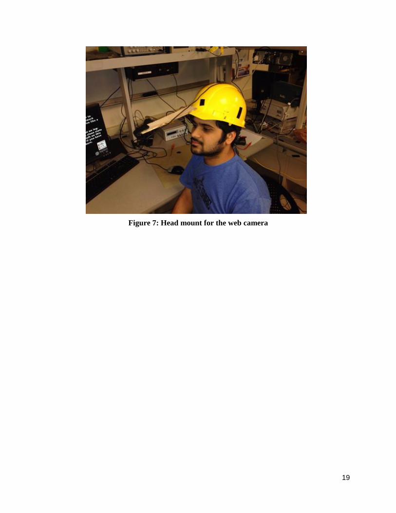
5. Mechanical Design
For the mechanical part, we worked on two things: the wheel chair prototype and the web
camera mount. For the wheel chair mount, we have tried to build the small prototype from wood
with four wheels that are connected to the motors. The photo shown below shows the wheel
chair prototype.
Figure 6: Wheelchair assembly
Now, in order to detect the eye movements, we need to have a web camera in front of the user.
For simplicity, we are attaching the web camera onto the head mount like helmet that will be
used to detect the eye motion. Since, we are not making the actual wheel chair, thus, we have to
use an independent head mount. Otherwise, we can use the web cam directly attach to the chair.
The photo of the head mount is given below.
19
Figure 7: Head mount for the web camera
20
6. Testing and Results
6.1 Testing Strategy
The debug screen was the most useful aspect of our testing strategy. The debug screen showed
whenever nothing was detected as a valid eye by the cascade object detector. When a valid eye is
seen, the length, height, x and y pixel co-ordinates are displayed on the debug screen. This is
done for every snapshot. After taking the difference between two snapshots, a tilt movement is
indicated by either saying ‘moved right’ or ‘moved left’.
Figure 8: MATLAB Debug Screen
After determining if the motor has to be moved or not and before transmitting the serial signal,
on the debug screen, we indicate the intended motion of the motor. This allows us to debug if
21
any error. If the movement suggested on the debug screen and then movement of the wheel chair
are in conjunction. This allowed us to test consistently with ease.
6.2 Speed of Execution
We were never actually limited by the speed of execution. We could go upto 15 frames a second,
evaluating and determining the face tilt. But there were couple of issues because of which we
limited the speed of execution. One being, we do not want the person to get a jerk whenever he
wants to move. Hence we compute and drive the motor at a slow pace, as compared to the ability
we can escalate the speed to. Also, we want to keep the system secure by taking a while to
evaluate the movement and thereafter making a decision, given the criticality of the application.
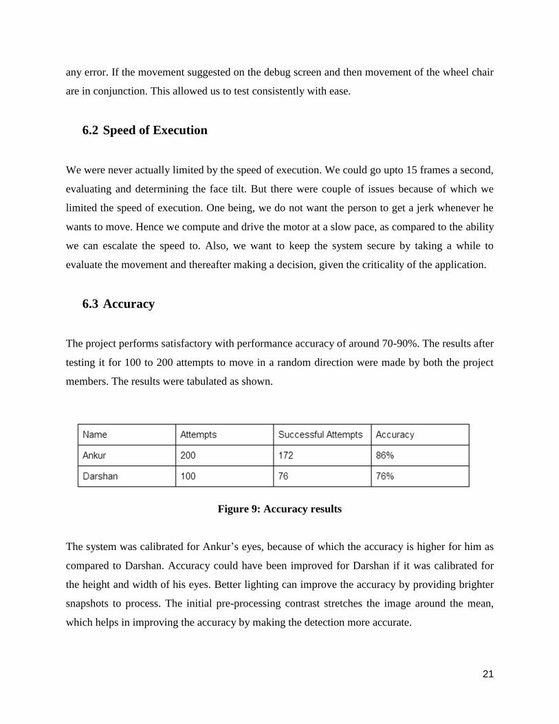
6.3 Accuracy
The project performs satisfactory with performance accuracy of around 70-90%. The results after
testing it for 100 to 200 attempts to move in a random direction were made by both the project
members. The results were tabulated as shown.
Figure 9: Accuracy results
The system was calibrated for Ankur’s eyes, because of which the accuracy is higher for him as
compared to Darshan. Accuracy could have been improved for Darshan if it was calibrated for
the height and width of his eyes. Better lighting can improve the accuracy by providing brighter
snapshots to process. The initial pre-processing contrast stretches the image around the mean,
which helps in improving the accuracy by making the detection more accurate.
22
Successful attempts were counted as all those attempts which resulted in movement of the wheel
chair in the desired direction. For the system to be accurate, each time a system is configured for
a person, alter the height and length of the specified eye so that the system recognizes the eye of
the person with high precision.
6.4 Safety Features
The safety features incorporated in the system were -
a) Controlled speed of detection and wheel chair drive.
b) Eye height and width threshold.
c) Controlled movement in either direction for limited time period.
d) Less jerk by incorporating delay in the wheel chair drive.
e) Halt control using blink detection.
23
7. Conclusions
7.1 Performance
The system functions with an accuracy rate of 70-90 % which was above our expectations. The
image capture, eye movement detection and the algorithm for validating movement attempts
perform very reliably as our results suggest.
The aim of this project is to contribute to the society in our small way by setting out an idea for a
system which could actually better the lives of millions of people across the globe. We believe
we have done great justice to the idea, and ended up getting more than satisfying results.
7.2 Future Modifications
Though our prototype performs satisfactorily, but a lot of work needs to be done before making
the product commercially viable. Some sort of sequence of events should trigger start of
detection, because we do not want the wheel chair to move when the person is just casually
glaring in different directions. Similarly, we can incorporate certain sequence for turning ON and
OFF electrical devices, or door locks.
Also since the criticality of the application is so high, lot of safety precautions need to be
incorporated. It needs to be made sure that the system is not fatal to the health of the person. A
lot of testing needs to be done before making such a product a reality.
24
Appendix A - User Manual
STEP 1: Install the webcam that is mounted on the helmet.
STEP 2: Connect the hardware circuit (motors connected to the controller) to the 6 volt supply
and also power the micro controller.
STEP 3: Wear the helmet on the head that will have the camera attached to it.
STEP 4: Program the microcontroller with the code given and also run the MATLAB script.
This will initiate the serial communication between the MATLAB script and the microcontroller.
STEP 5: Make the head movements that will be tracked which thereby will control the motors to
move in the expected direction.
25
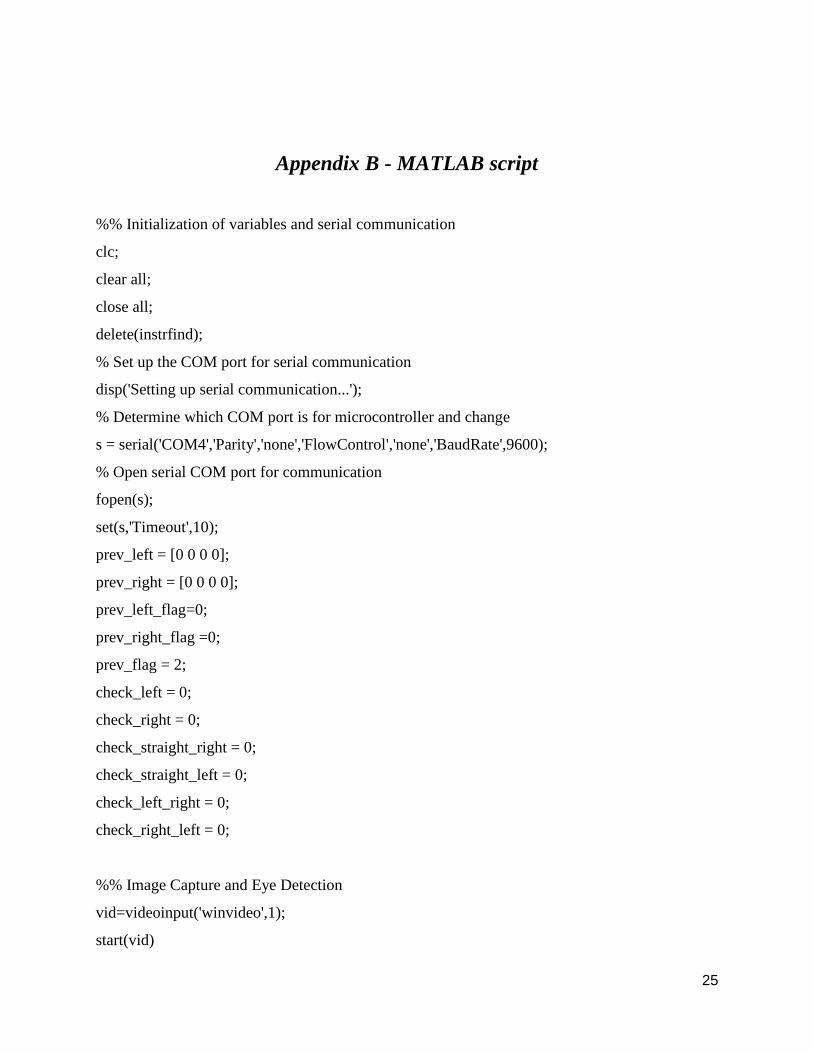
Appendix B - MATLAB script
%% Initialization of variables and serial communication
clc;
clear all;
close all;
delete(instrfind);
% Set up the COM port for serial communication
disp('Setting up serial communication...');
% Determine which COM port is for microcontroller and change
s = serial('COM4','Parity','none','FlowControl','none','BaudRate',9600);