MODEL XL-21 EYELET BUTTONHOLE MACHINE PARTS AND SERVICE MANUAL MACHINE SERIAL No. PART NUMBER 97. 1800.2.002 AMF is trademark of AMF Group, Inc. This manual is valid from the machine serial No.: F180291
Transcript
MODEL XL-21
EYELET BUTTONHOLE MACHINE
PARTS AND SERVICE MANUAL
MACHINE SERIAL No.
PART NUMBER 97. 1800.2.002
AMF is trademark of AMF Group,Inc.
This manual is valid from the machine serial No.: F180291
XL
-21EY
ELET BUTTO
NH
OLE
PARTS A
ND
SERVIC
E MA
NU
AL
P/N 97.1800.2.002
XL
-21EY
ELET BUTTO
NH
OLE
PARTS A
ND
SERVIC
E MA
NU
AL
P/N 97.1800.2.002
XL
-21EY
ELET BUTTO
NH
OLE
PARTS A
ND
SERVIC
E MA
NU
AL
P/N 97.1800.2.002
XL
-21EY
ELET BUTTO
NH
OLE
PARTS A
ND
SERVIC
E MA
NU
AL
P/N 97.1800.2.002
XL
-21EY
ELET BUTTO
NH
OLE
PARTS A
ND
SERVIC
E MA
NU
AL
P/N 97.1800.2.002
XL
-21EY
ELET BUTTO
NH
OLE
PARTS A
ND
SERVIC
E MA
NU
AL
P/N 97.1800.2.002
XL
-21EY
ELET BUTTO
NH
OLE
PARTS A
ND
SERVIC
E MA
NU
AL
P/N 97.1800.2.002
LIMITED WARRANTY ON NEW AMF REECE EQUIPMENT
Warranty provisions:
A ninety (90) day limited service labor warranty to correct defects in installation, workmanship, or material without charge forlabor. This portion of the warranty applies to machines sold as ”installed” only.
A one (1) year limited material warranty on major component parts to replace materials with defects. Any new part believeddefective must be returned freight prepaid to AMF Reece, Inc. for inspection. If, upon inspection, the part or material is deter-mined to be defective, AMF Reece, Inc. will replace it without charge to the customer for parts or material.
Service labor warranty period shall begin on the completed installation date. Material warranty shall begin on the date theequipment is shipped from AMF Reece, Inc.
Exclusions:
Excluded from both service labor warranty and material warranty are: (1) Consumable parts which would be normally consideredreplaceable in day-to-day operations. These include parts such as needles, knives, loopers and spreaders. (2) Normal adjustmentand routine maintenance. This is the sole responsibility of the customer. (3) Cleaning and lubrication of equipment. (4) Partsfound to be altered, broken or damaged due to neglect or improper installation or application. (5) Damage caused by the use ofnon-Genuine AMF Reece parts. (6) Shipping or delivery charges.
There is no service labor warranty for machines sold as ”uninstalled”.
Equipment installed without the assistance of a certified technician (either an AMF Reece Employee, a Certified Contractor, orthat of an Authorized Distributor) will have the limited material warranty only. Only the defective material will be covered. Anycharges associated with the use of an AMF Reece Technician or that of a Distributor to replace the defective part will be thecustomer’s responsibility.
NO OTHER WARRANTY, EXPRESS OR IMPLIED, AS TO DESCRIPTION, QUALITY, MERCHANTABILITY, and FITNESS FORA PARTICULAR PURPOSE, OR ANY OTHER MATTER IS GIVEN BY SELLER OR SELLER’S AGENT IN CONNECTION HERE-WITH. UNDER NO CIRCUMSTANCES SHALL SELLER OR SELLER’S AGENT BE LIABLE FOR LOSS OF PROFITS OR ANYOTHER DIRECT OR INDIRECT COSTS, EXPENSES, LOSSES OR DAMAGES ARISING OUT OF DEFECTS IN OR FAILURE OFTHE EQUIPMENT OR ANY PART THEREOF.
WHAT TO DO IF THERE IS A QUESTION REGARDING WARRANTY
If a machine is purchased through an authorized AMF Reece, Inc. distributor, warranty questions should be first directed to thatdistributor. However, the satisfaction and goodwill of our customers are of primary concern to AMF Reece, Inc. In the event thata warranty matter is not handled to your satisfaction, please contact the appropriate AMF Reece office:
INSTALLATIONStitch Drive Belt Tension ............................................................................................... 1-7Table Move Drive Belt Tension ..................................................................................... 1-7Thread Stand and Preparation to Sew ......................................................................... 1-8
ADJUSTMENTLateral Cam For the Eye Shape .................................................................................... 1-59Changing the Stitch Bite Width ...................................................................................... 1-60Last Stitch Stop ............................................................................................................ 1-61Cutting Space ............................................................................................................... 1-62Buttonhole Shape and the Inside Cut Length .................................................................. 1-63Elements for Buttonhole Length ..................................................................................... 1-64Needle Bar Height ........................................................................................................ 1-68Loopers and Needle Timing .......................................................................................... 1-69Spreader Open/Close Timing ........................................................................................ 1-73Knife and Cutting Lever ................................................................................................ 1-74Cutting Knives .............................................................................................................. 1-74Changing the Knife and Cutting Steel ............................................................................. 1-75Top Thread Picker Mechanism and Trimming ................................................................ 1-76Gimp Control Mechanism ............................................................................................. 1-77Cord Trim Mechanism Adjustment ................................................................................ 1-77Clamp Plate Installation ................................................................................................. 1-82Trim Delay .................................................................................................................... 1-83Lateral Cam Blocks Cut Before and Cut After .............................................................. 1-84Adjustment of the Height of the Upper Thread Trim Knife .............................................. 1-85Adjustment of the Thread Retainer ................................................................................ 1-85Trim Knife Travel .......................................................................................................... 1-86Thread Trimming Timing ................................................................................................ 1-89
ELECTRICAL DIAGRAM XL-21, XL-21 ST ........................................................................ 1-90
PNEUMATIC DIAGRAMPower and air connection .............................................................................................. 1-91Pneumatic diagram XL-21 ............................................................................................ 1-91Pneumatic diagram XL-21 ST ....................................................................................... 1-92
MACHINE MAINTENANCEPreventive Maintenance ................................................................................................ 1-93Recommendation for Machine Maintenance .................................................................. 1-94
SPECIAL PARTSClamp Feet for Sewing Heavy or Thin Fabrics .............................................................. 1-95Changing the Manual Start-Up for the Pedal Start-Up ................................................... 1-96Upper Thread Draw-Off ............................................................................................... 1-97
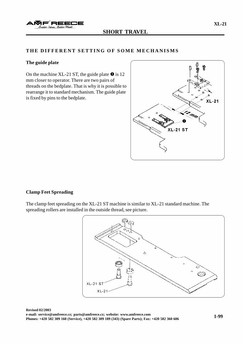
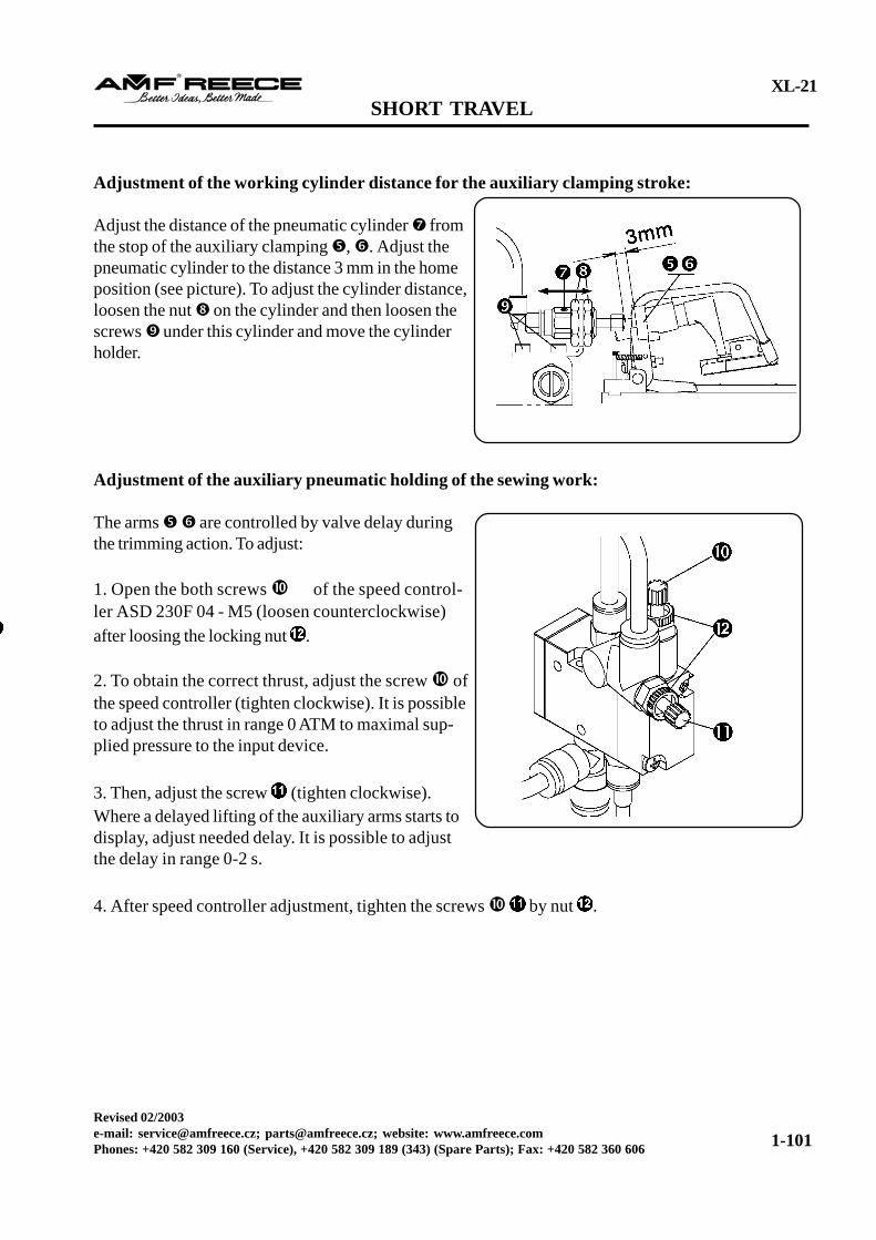
SHORT TRAVELIntroduction .................................................................................................................. 1-98The different setting of some mechanisms ....................................................................... 1-99The auxiliary fabric clamping adjustment ........................................................................ 1-100
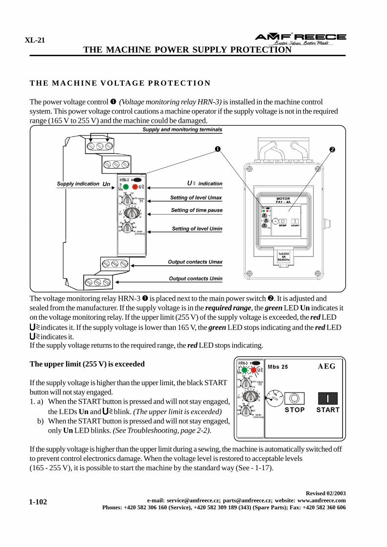
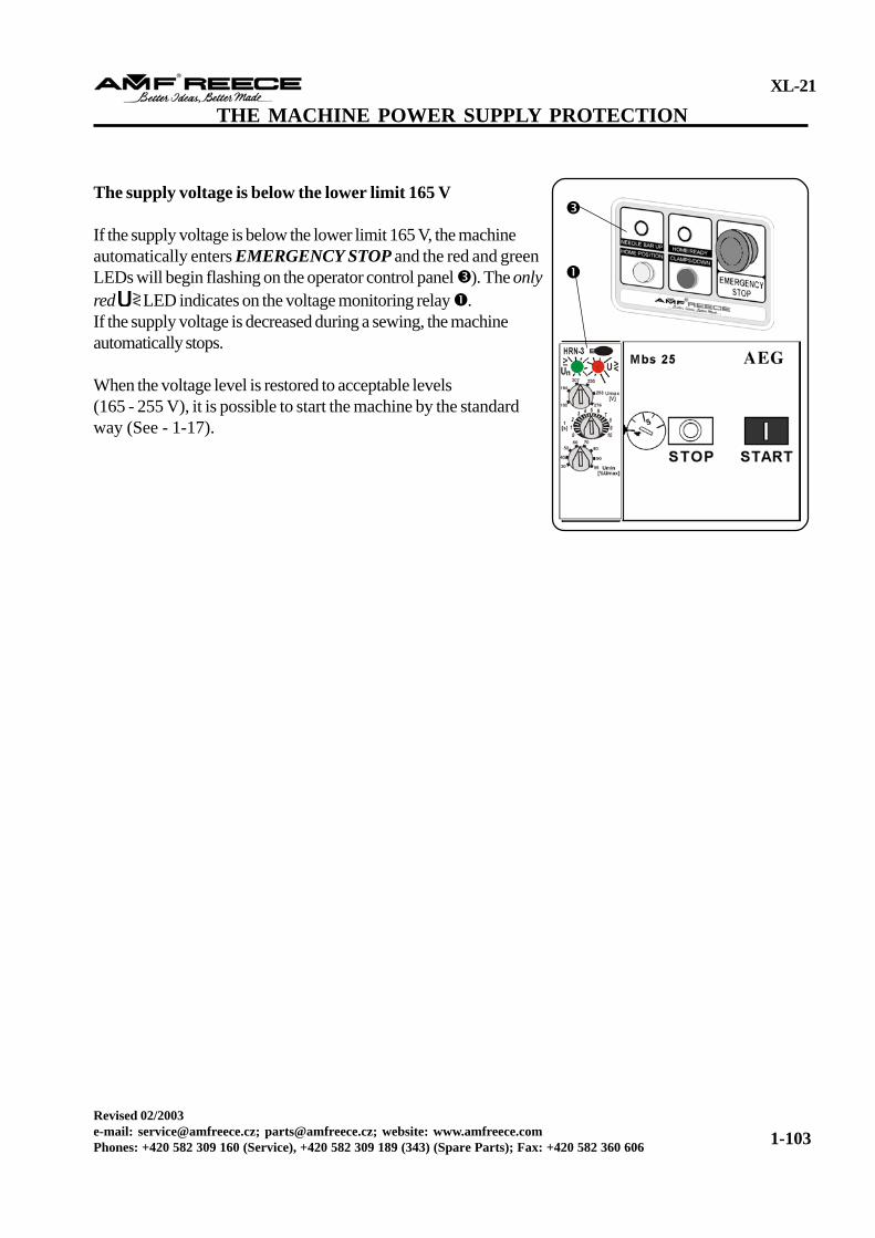
THE MACHINE POWER SUPPLY PROTECTIONThe machine voltage protection ..................................................................................... 1-102
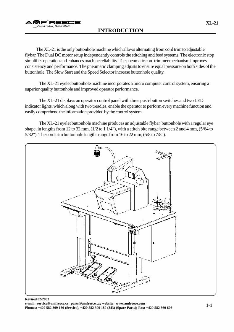
The XL-21 is the only buttonhole machine which allows alternating from cord trim to adjustableflybar. The Dual DC motor setup independently controls the stitching and feed systems. The electronic stopsimplifies operation and enhances machine reliability. The pneumatic cord trimmer mechanism improvesconsistency and performance. The pneumatic clamping adjusts to ensure equal pressure on both sides of thebuttonhole. The Slow Start and the Speed Selector increase buttonhole quality.
The XL-21 eyelet buttonhole machine incorporates a micro computer control system, ensuring asuperior quality buttonhole and improved operator performance.
The XL-21 displays an operator control panel with three push-button switches and two LEDindicator lights, which along with two treadles, enable the operator to perform every machine function andeasily comprehend the information provided by the control system.
The XL-21 eyelet buttonhole machine produces an adjustable flybar buttonhole with a regular eyeshape, in lengths from 12 to 32 mm, (1/2 to 1 1/4"), with a stitch bite range between 2 and 4 mm, (5/64 to5/32"). The cord trim buttonhole lengths range from 16 to 22 mm, (5/8 to 7/8").
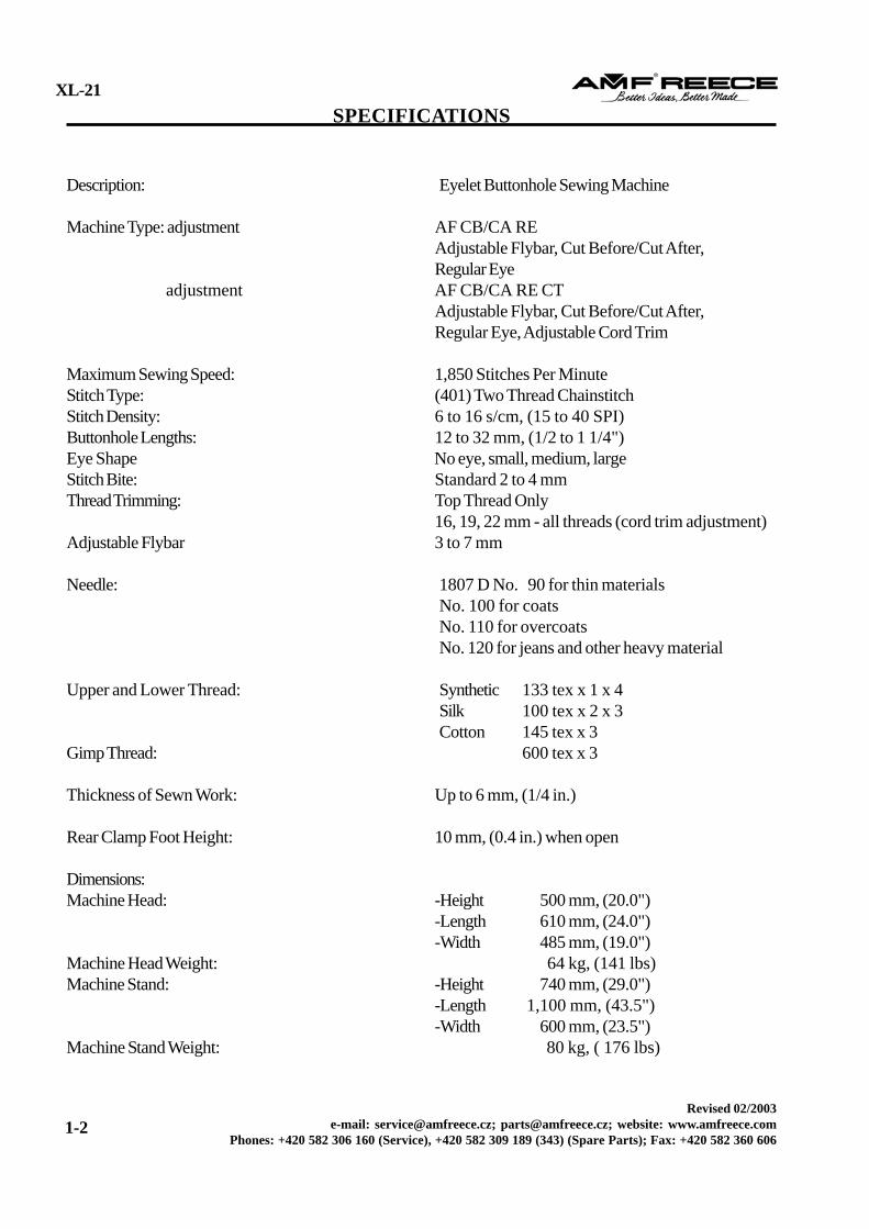
adjustment AF CB/CA RE CTAdjustable Flybar, Cut Before/Cut After,Regular Eye, Adjustable Cord Trim
Maximum Sewing Speed: 1,850 Stitches Per MinuteStitch Type: (401) Two Thread ChainstitchStitch Density: 6 to 16 s/cm, (15 to 40 SPI)Buttonhole Lengths: 12 to 32 mm, (1/2 to 1 1/4")Eye Shape No eye, small, medium, largeStitch Bite: Standard 2 to 4 mmThread Trimming: Top Thread Only
16, 19, 22 mm - all threads (cord trim adjustment)Adjustable Flybar 3 to 7 mm
Needle: 1807 D No. 90 for thin materialsNo. 100 for coatsNo. 110 for overcoatsNo. 120 for jeans and other heavy material
Upper and Lower Thread: Synthetic 133 tex x 1 x 4Silk 100 tex x 2 x 3Cotton 145 tex x 3
Gimp Thread: 600 tex x 3
Thickness of Sewn Work: Up to 6 mm, (1/4 in.)
Rear Clamp Foot Height: 10 mm, (0.4 in.) when open
Dimensions:Machine Head: -Height 500 mm, (20.0")
-Length 610 mm, (24.0")-Width 485 mm, (19.0")
Machine Head Weight: 64 kg, (141 lbs)Machine Stand: -Height 740 mm, (29.0")
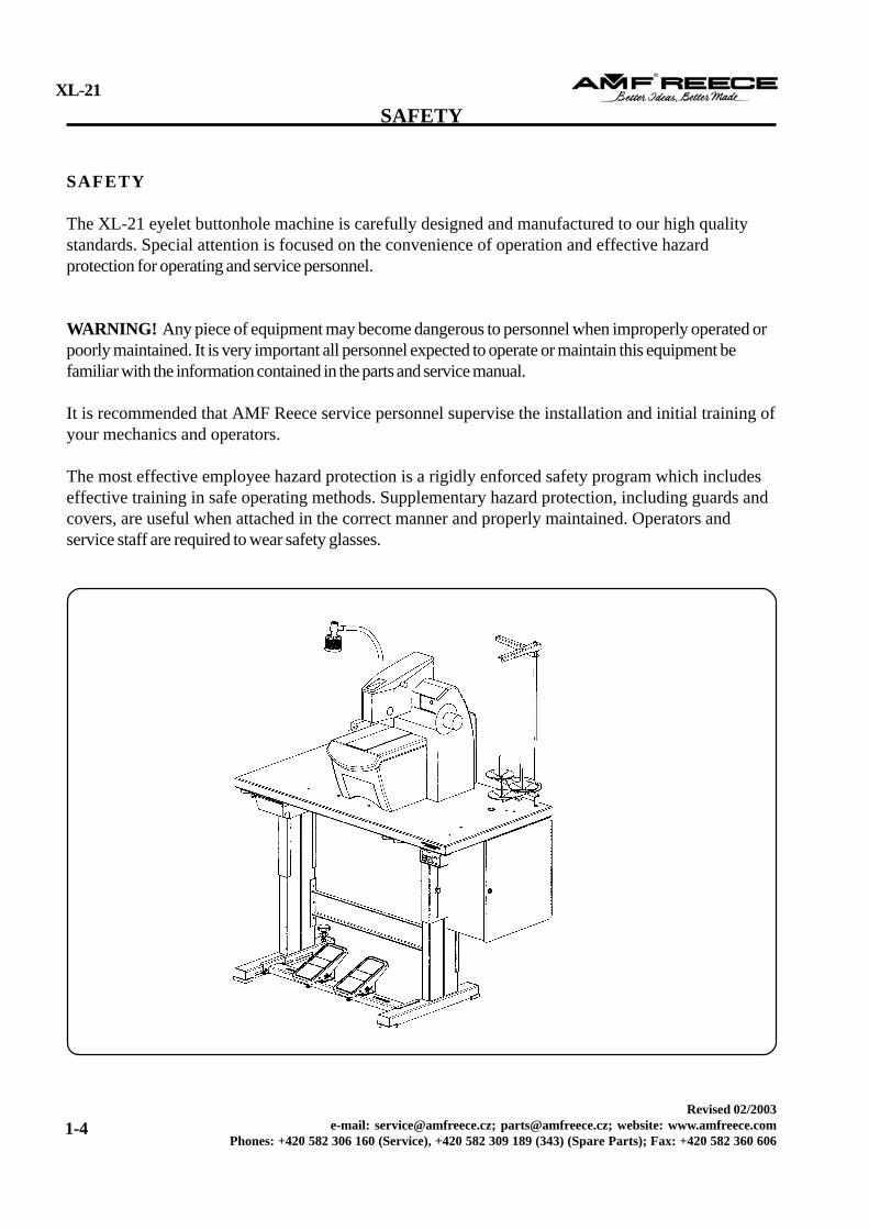
The XL-21 eyelet buttonhole machine is carefully designed and manufactured to our high qualitystandards. Special attention is focused on the convenience of operation and effective hazardprotection for operating and service personnel.
WARNING! Any piece of equipment may become dangerous to personnel when improperly operated orpoorly maintained. It is very important all personnel expected to operate or maintain this equipment befamiliar with the information contained in the parts and service manual.
It is recommended that AMF Reece service personnel supervise the installation and initial training ofyour mechanics and operators.
The most effective employee hazard protection is a rigidly enforced safety program which includeseffective training in safe operating methods. Supplementary hazard protection, including guards andcovers, are useful when attached in the correct manner and properly maintained. Operators andservice staff are required to wear safety glasses.
1. Put the thread stand togetheraccording to the drawing.
2. Position of the locking ring allows assembly of the threadstand for various thickness ofthe bedplate. Threading end ofthe rod can not overlap thenut more than 1 mm (0,039“).
3. After adjustment of the lockingring , insert the washer byrecess to the locking ring andinsert the rod to the right rearhole in the bedplate Tightenthe nut, under which is washer .
P R E PA R AT I O N TO S E W
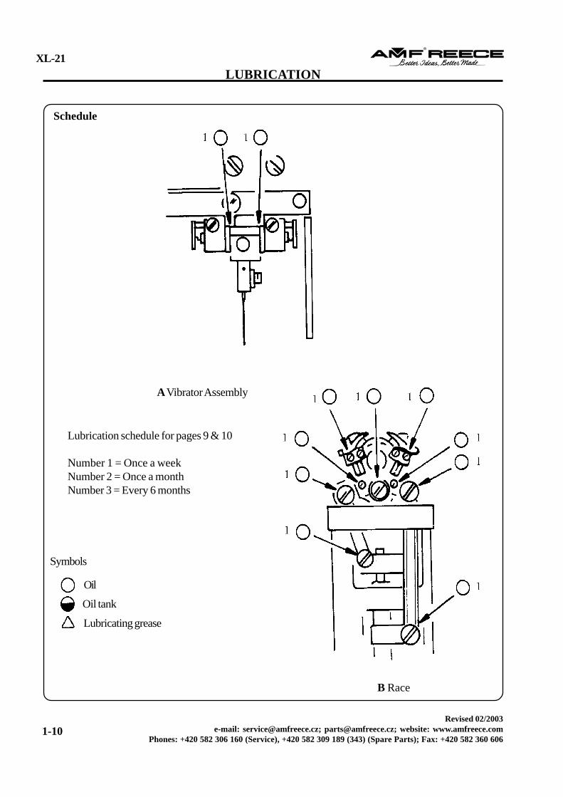
Observe all safety requirements and ensure all covers are installed.Check for the proper operation of each machine control switch.Ensure the sewing head is properly lubricated.Check for correct needle installation, size, condition, and ensure proper thread tension and type.Perform a final check for correct sewing performance and operation of all machine components.Ensure the display indicates the machine is in the correct home position.
Ensure the areas illustrated are properly lubricated.The correct amount of oil required for the oil tank, on the right-hand side of the machine, must not exceedthe red mark level indicator, located in the center of the gauge. Too much oil added, may leak around theneedle bar.The correct amount of oil required for the oil reservoir, located inside the right cover, is 5 mm.Too much oil may leak.Using a scrap piece of fabric, cycle the machine 20 times to eliminate any excess oil.
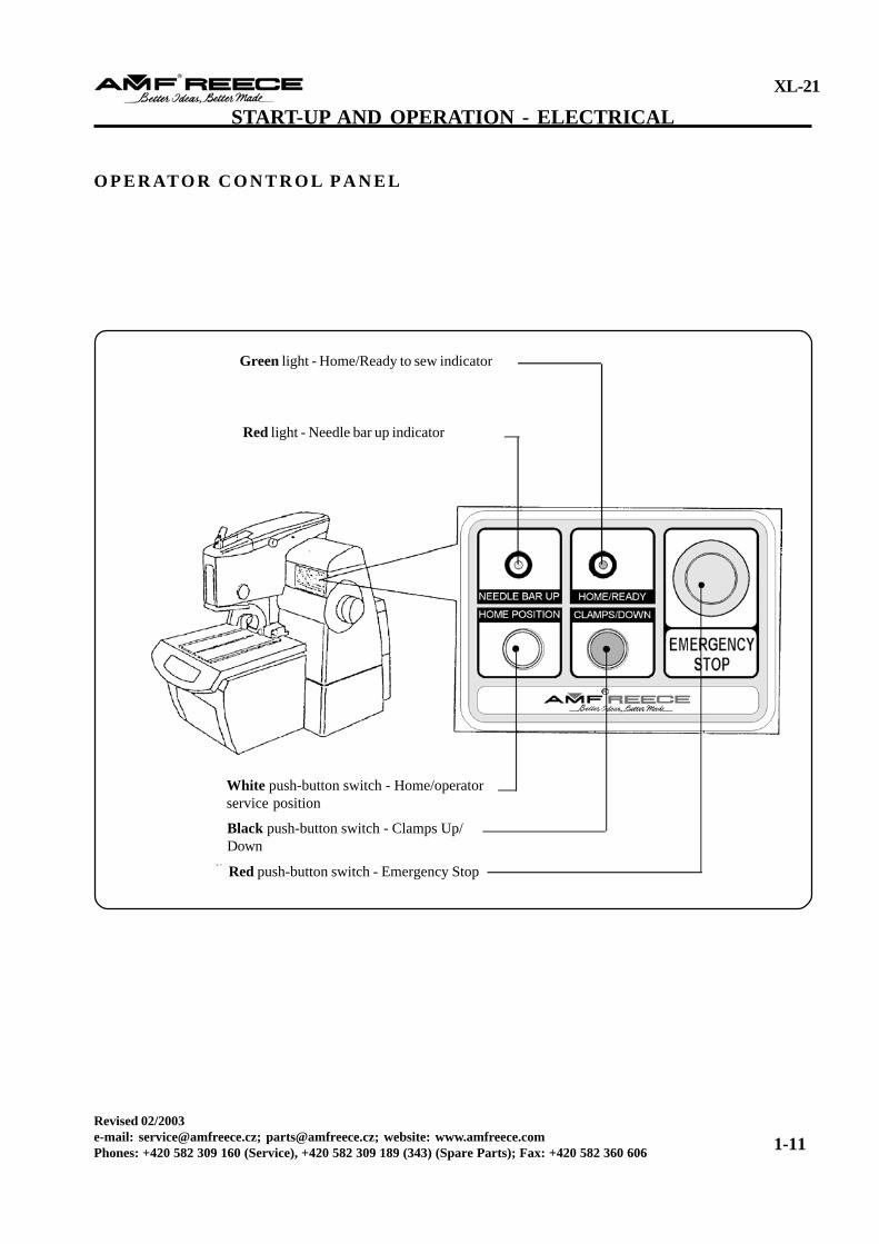
The AMF Reece XL-21 is equipped with a micro computer control system designed to improveperformance and drastically reduce the maintenance required to operate an eyelet buttonhole machine.Three switches, two treadles, and two indicator lights make it easy to control every function and understandthe information provided by the system.
T R E A D L E F U N C T I O N SThe right start treadle incorporates two different modes of operation. The first mode controls lowering andlifting the clamps, the second mode starts the sewing cycle. The start treadle has 2 stages. Lightly toed downto the first stage, the clamps are lowered, if the treadle is released to the home position, the clamps arerisen. Toed all the way down, the material is automatically clamped and the sewing cycle begins.
The left Emergency treadle, when toed all the way down, does not release the clamps after finishing thesewing cycle. Before sewing the next buttonhole release the emergency treadle, or damage may occur to theneedle/sewing mechanism.
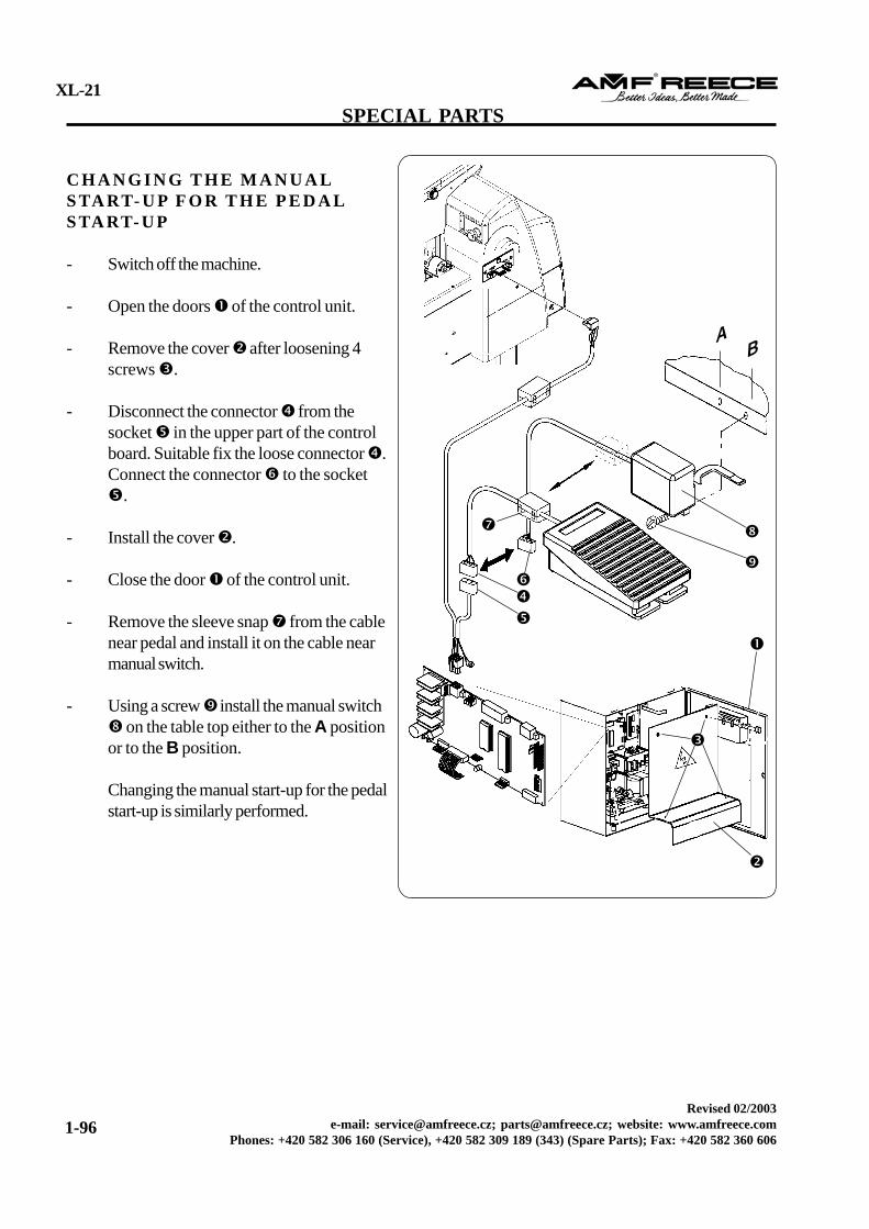
Manual start-upIt compensates for the right pedal. The manual switch “Start” has two functions. Thefirst function starts and lifts the clamp feet and the second starts sewing. The Startswitch has two positions. If the switch lever is pressed to the first position, the clampfeet are lowered. If the switch lever is returned to the home position, the clamp feet
return to the upper position. If the lever is pressed maximum down, the material is clamped and the sewingstarts. Manual start-up is supplied as a special acessories on a special order.N o t e : Either pedal or manual switch can be connected. Changing the manual start-up for the pedal start-up - see page 1-96.O P E R ATO R P U S H - B U T TO N S W I T C H E SHome/Operator Service Position Switch
When pressed, the white Home Switch, located on the operator control panel, moves themachine table back to the home position and eliminates accidental machine starting duringthreading, a needle change, and clamp plate installation. When pressed in the home position, themachine travels to the operator service position and stops, pressed a second time, the machinewill travel to the home position. The machine will not operate until the white push-button isengaged the second time.
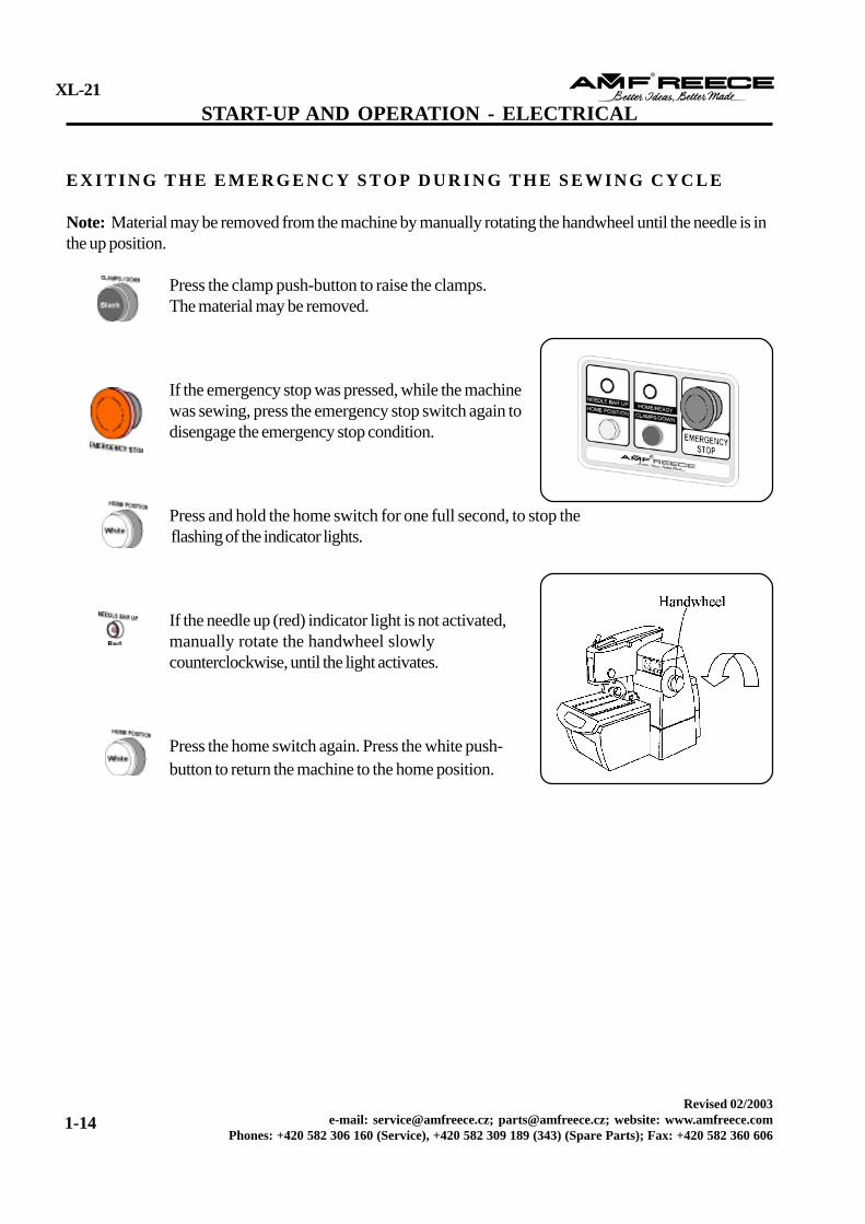
Clamp SwitchWhen pressed, the black Clamp Switch, located on the operator control panel, manually raisesand lowers the clamps holding the material. A toggle switch, pressing it once lowers the clamps,pressing again raises the clamps.
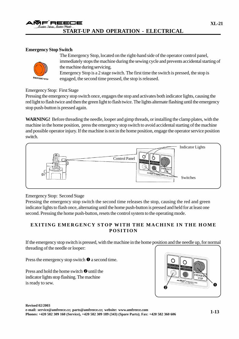
Emergency Stop SwitchThe Emergency Stop, located on the right-hand side of the operator control panel,immediately stops the machine during the sewing cycle and prevents accidental starting ofthe machine during servicing.Emergency Stop is a 2 stage switch. The first time the switch is pressed, the stop isengaged, the second time pressed, the stop is released.
Emergency Stop: First StagePressing the emergency stop switch once, engages the stop and activates both indicator lights, causing thered light to flash twice and then the green light to flash twice. The lights alternate flashing until the emergencystop push-button is pressed again.
WARNING! Before threading the needle, looper and gimp threads, or installing the clamp plates, with themachine in the home position, press the emergency stop switch to avoid accidental starting of the machineand possible operator injury. If the machine is not in the home position, engage the operator service positionswitch.
Indicator Lights
Switches
Emergency Stop: Second StagePressing the emergency stop switch the second time releases the stop, causing the red and greenindicator lights to flash once, alternating until the home push-button is pressed and held for at least onesecond. Pressing the home push-button, resets the control system to the operating mode.
E X I T I N G E M E R G E N C Y S T O P W I T H T H E M A C H I N E I N T H E H O M EP O S I T I O N
If the emergency stop switch is pressed, with the machine in the home position and the needle up, for normalthreading of the needle or looper:
Press the emergency stop switch a second time.
Press and hold the home switch until theindicator lights stop flashing. The machineis ready to sew.
The red Needle Up light, located on the control panel, indicates the needle bar is in the correct upposition.
Note: The machine will not operate unless the needle bar is in the up position. If the light is notactivated, manually rotate the handwheel slowly counterclockwise, until it activates. The machine is nowready to sew.
The green Home/Ready to Sew light, located on the control panel, indicates the machine is in the homeposition and ready for normal sewing.
Note: If both the red and green lights are flashing at the same time, a system error has occurred, calla technician to reset the machine.
S TA RT / S TO P S W I T C H E S
The Start and Stop switches, located beneath the tabletop on the right-hand side, regulate the main electricalpower to the XL-21.
Press the black switch to engage the power.
Press the red switch to disengage the power.
WARNING! Ensure the main power is off when threading the machine, the looper, and the gimp.
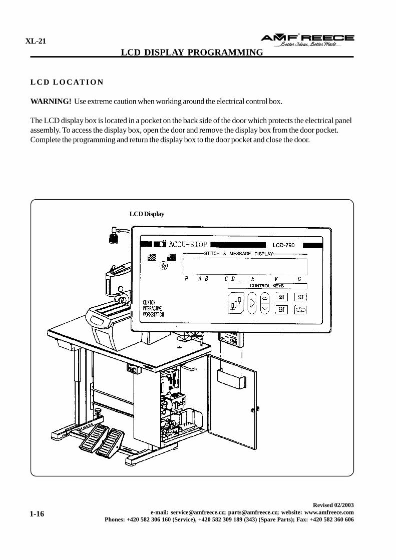
WARNING! Use extreme caution when working around the electrical control box.
The LCD display box is located in a pocket on the back side of the door which protects the electrical panelassembly. To access the display box, open the door and remove the display box from the door pocket.Complete the programming and return the display box to the door pocket and close the door.
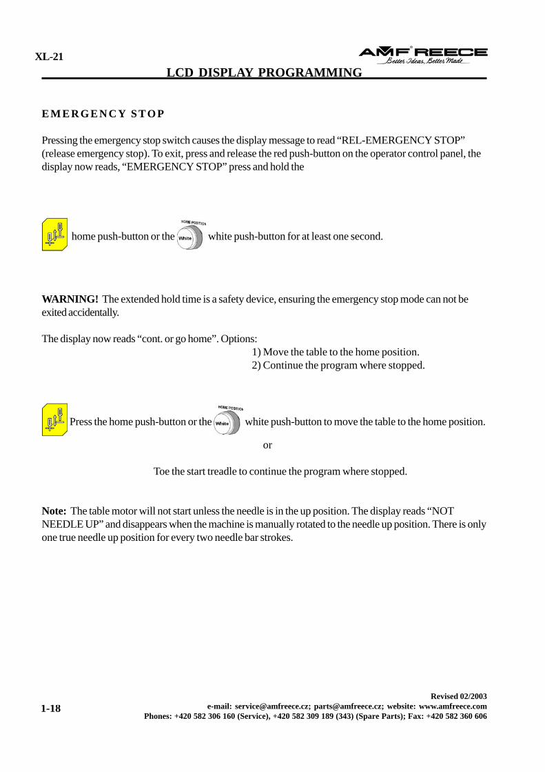
Pressing the emergency stop switch causes the display message to read “REL-EMERGENCY STOP”(release emergency stop). To exit, press and release the red push-button on the operator control panel, thedisplay now reads, “EMERGENCY STOP” press and hold the
home push-button or the white push-button for at least one second.
WARNING! The extended hold time is a safety device, ensuring the emergency stop mode can not beexited accidentally.
The display now reads “cont. or go home”. Options: 1) Move the table to the home position. 2) Continue the program where stopped.
Press the home push-button or the white push-button to move the table to the home position.
or
Toe the start treadle to continue the program where stopped.
Note: The table motor will not start unless the needle is in the up position. The display reads “NOTNEEDLE UP” and disappears when the machine is manually rotated to the needle up position. There is onlyone true needle up position for every two needle bar strokes.
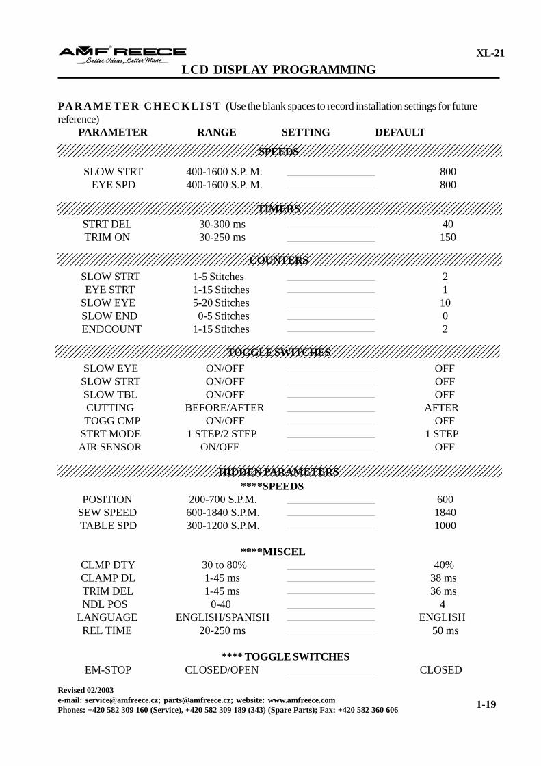
SLOW EYE ON/OFF OFF SLOW STRT ON/OFF OFF SLOW TBL ON/OFF OFF CUTTING BEFORE/AFTER AFTER TOGG CMP ON/OFF OFF STRT MODE 1 STEP/2 STEP 1 STEP AIR SENSOR ON/OFF OFF
****SPEEDS POSITION 200-700 S.P.M. 600 SEW SPEED 600-1840 S.P.M. 1840 TABLE SPD 300-1200 S.P.M. 1000
****MISCEL CLMP DTY 30 to 80% 40% CLAMP DL 1-45 ms 38 ms TRIM DEL 1-45 ms 36 ms NDL POS 0-40 4 LANGUAGE ENGLISH/SPANISH ENGLISH REL TIME 20-250 ms 50 ms
When the display is set to Full Cycle, the machine is ready to automatically sew a complete buttonhole. Toethe start treadle to begin the sewing cycle and the table motor will move the table from the home position tothe sew position.
Note: Sewing speed may be adjusted up to 1,850 spm.
In the sew position, the table motor stops, the sew motor starts, and the following options may be selected:
1) Slow start 2) Slow end
To overlap the last stitch with the first stitch, use the adjustable stitch counter.The table motor starts again and moves the table back to the home position. While moving to home,the hole is punched. Once the hole is punched, the clamps may be raised before the table reaches thehome position.
The Single Step mode provides the option of stepping through each operation for easy adjustmentsand maintenance. To access:Toe the Start treadle and the table moves to the sew position.Toe the Start treadle again to sew the buttonhole.Toe the Start treadle a third time and the table moves back to the home position, after punching the hole andlifting the clamps.
The Move Table Only mode, primarily for adjusting the buttonhole puncher, moves the table onlyfrom home to home position.
Toe and fully release the Start treadle. The table moves to the sew position and stops. Slowly toe theStart treadle to the first stage, until the clamps lower into the normal operating mode. The tablemoves very slowly through the cycle. Release the treadle and the machine stops. Toe the treadlefully down and the machine begins sewing and completes the cycle.
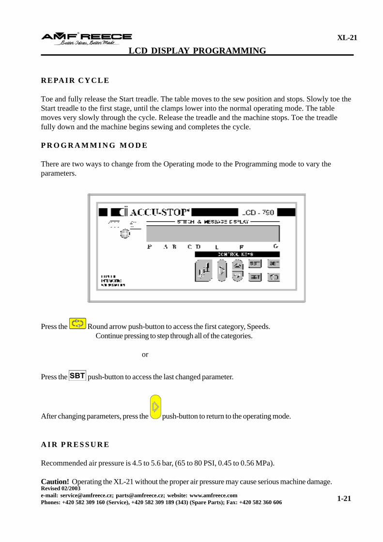
P R O G R A M M I N G M O D E
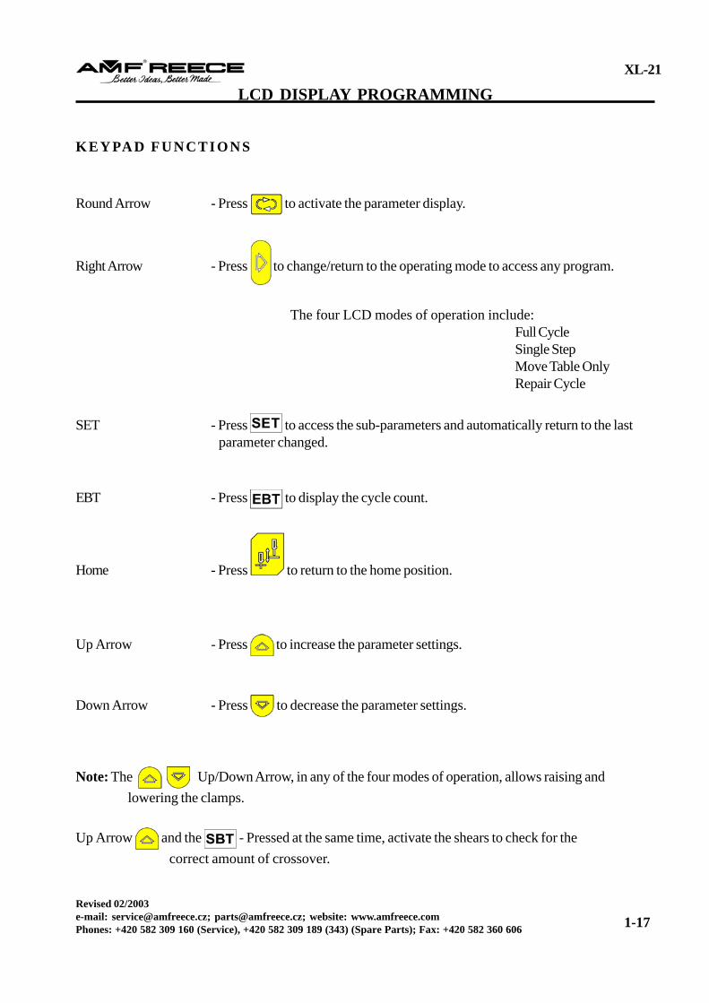
There are two ways to change from the Operating mode to the Programming mode to vary theparameters.
Press the Round arrow push-button to access the first category, Speeds.Continue pressing to step through all of the categories.
or
Press the push-button to access the last changed parameter.
After changing parameters, press the push-button to return to the operating mode.
A I R P R E S S U R E
Recommended air pressure is 4.5 to 5.6 bar, (65 to 80 PSI, 0.45 to 0.56 MPa).
Caution! Operating the XL-21 without the proper air pressure may cause serious machine damage.
SLOW STRT - Allows sewing the first stitches at the beginning and the last stitches at the end of thebuttonhole in a slower speed. To vary the number of stitches, see the parameter group Counters. To enableor disable this function, see the parameter group Toggle Switches, set by the software.
Ranges: 400 to 1,600 spmSteps: 10 spmDefault Setting: 800 spm
EYE SPD - The slow eye function determines the number of stitches/speed, the eye will be sewn.Not presently available. To enable or disable, select the parameter group Toggle Switches.To vary the number of stitches, select the parameter group Counters.
Ranges: 400 to 1,600 spmSteps: 10 spmDefault Setting: 800 spm
TIMERS (ms, Milliseconds)
STRT DEL (Start Delay) - Delays the start (motor) after toeing the Start treadle fully down with theclamps in the Up position, allows the clamps time to lower and hold the material before the machine startssewing. If the clamp is Down, this time delay will have no affect.
Range: 30 to 300 msSteps: 10 msDefault Setting: 40 ms
TRIM ON (Pneumatic shears only) - Establishes the amount of time the shears solenoid is energized.
Range: 30 to 300 msSteps: 10 msDefault Setting: 150 ms
Note: When the range selected is 260 ms, the trim on function will not activate.
SLOWSTRT (Soft or Slow Start) - The number of stitches sewn with limited speed, after starting thesewing mode.
Range: 1 to 5 stitchesSteps: 1 stitchDefault Setting: 2 stitches
EYE STRT (Eye Start) - The Slow Eye sensor is stationary, no mechanical adjustments are available. Thenumber of stitches selected, determines the beginning of the slow eye. Increasing the number makes theslow eye start later.
Range: 1 to 15 stitchesSteps: 1 stitchDefault Setting: 1 stitch
SLOW END - The number of end stitches sew in the slow speed mode.
Range: 0 to 15 stitchesSteps: 1 stitchDefault Setting: 0 stitches
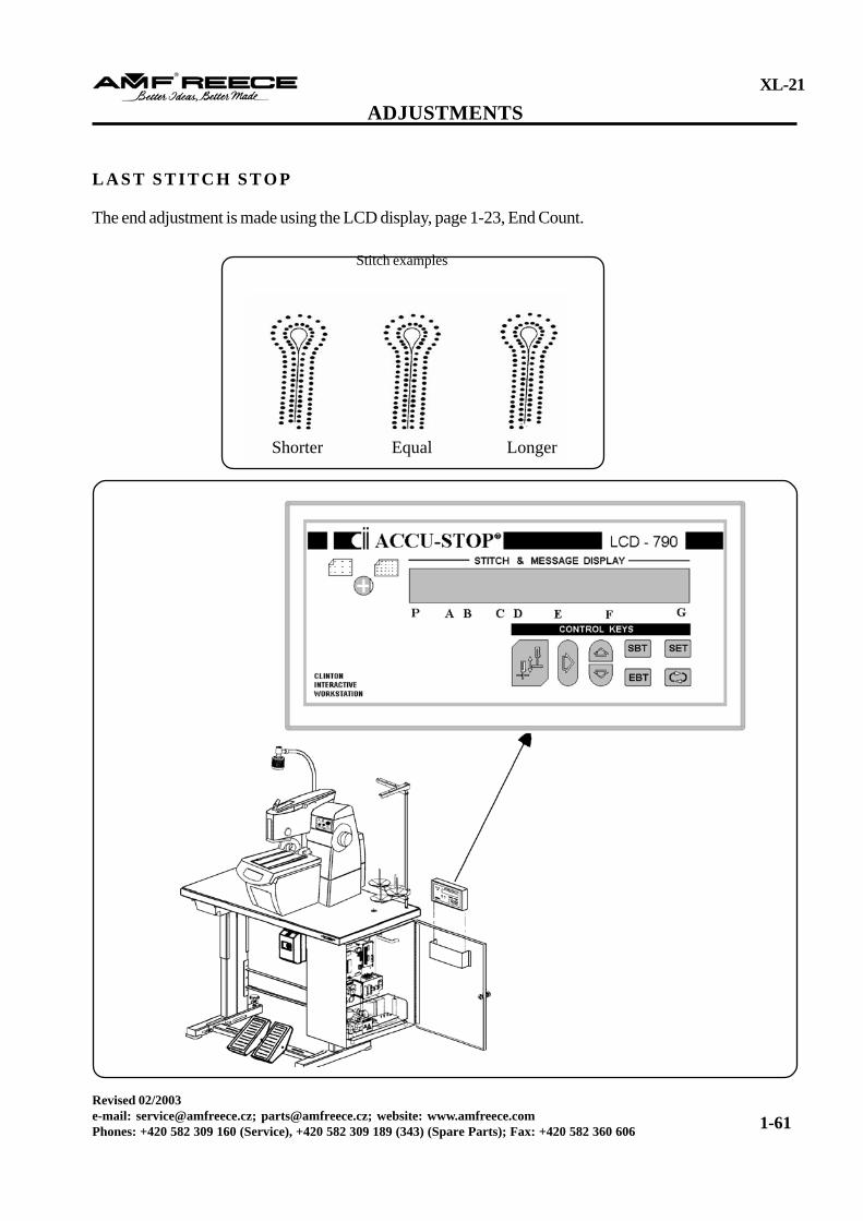
ENDCOUNT - The number of stitches sewn after sensing the last stitch.
Range: 1 to 15 stitchesSteps: 1 stitchDefault Setting: 2 stitches
Caution! To keep the knives from breaking the needle, the minimum setting for cord trimming is 3 stitches.
SLOWSTRT (Slow Start) - Switches the Slow Start mode on or off.
Default Setting: Off
SLOW TBL (Slow Table) -
Note: This parameter is ONLY used in the three sensor version.
On: The first edge of the sew sensor slows the table to half speed.Off: The table goes full speed to stop.Default Setting: Off
CUTTING - This function sets the system for Cut Before or Cut After stitching.
Default Setting: After
TOGG CMP (Toggle Clamp) - On, causes the clamps to remain in the Down position even if the Startswitch is released, the clamps remain down until the Start switch is depressed a second time. Off, the clampwill feather with the Start switch.
Default Setting: Off
STRT MODE (Toggle Switches) - For the “Full Cycle” mode only.
1 Step: First stage of the Start switch automatically starts the sewing cycle.2 Step: First stage of the Start switch operates the clamps, the second stage starts the new cycle.
Default Setting: 1 Step
NO AIR PRESSURE (Air Pressure Sensor) - When insufficient air pressure is detected, the red indicatorlight on the pressure gauge activates. To avoid machine damage, the machine will not operate, until aminimum 4.2 bar, (60 PSI) air pressure is detected.
CLMP DTY (Clamp Duty Cycle) - Based on the percentage of current applied to keep the solenoidenergized, the duty cycle must be set to the minimum value required, when the solenoid is energized.
Caution! Set too high, the solenoid may turn hot and the de-energized time will be too long. Set too low,the solenoid vibrates (creating noise) and the clamps may drop.
Range: 30% to 80%Steps: 1Default Setting: 40%
CLMP DL (Clamp Delay) - The set time the clamps release. When the number is decreased, the clampslift quicker. If the number selected, is too low, the clamps lift before trimming. When sewing thicker fabrics,the selected time must be reduced, (example: jeans 29 ms), otherwise the thread trim knife will cut thefabric.
Note: The lower the number, the quicker the clamps will lift.
Range: 1 to 45 msSteps: 1Default Setting: 38 ms
TRIM DEL (Trim Delay) - Determines when the cutter activates. 1-14 ms: trims before the cut, (this scale if not always functional)15-33 ms: shears are contacting the knife34-41 ms: trims after the cut
Note: This parameter is important to the delay time.
NDL POS (Needle Position) - The amount of power applied to the motor (in the reverse mode) duringstopping for accurate needle positioning. If the braking current number is too low, the machine mayovershoot, if too high, the machine may bounce back.
Note: The higher the number, the stronger the brake force.
Range: 0 to 40Steps: 1Default Setting: 4
Caution! If the table overshoots the “HOME POSITION” (and the display reads “not home”), do not tryto correct the problem by adjusting the “NEEDLE POS” parameter. (The parameter does not affect thetable motor because of the one-way bearing in the table pulley). Adjust the HOME SENSOR, lower theTABLE SPEED, or choose the SLOW TABLE function, page 1-24.
LANGUAGE - The languages available are English and Spanish.
Default Setting: English
REL TIME (Relay Time) - delays the start of the table motor after the sew head has been positioned tocompensate for the delay of the relay. If the time delay is too short, the relay may arc (spark) and the needlemay move out of position, if the start pulse for the table motor goes to the sew motor.
Range: 20-250 msSteps: 1Default Setting: 50 ms
****TOGGLE SWITCHES
EM/STOP (Emergency Stop) - Controls the program according to the switch wiring connections.
Normally Open - when the push-button is pressed, the switching contact (C-NO) is connected.Normally Closed - when the push-button is pressed, the switch off contact (C-NC] is disconnected.
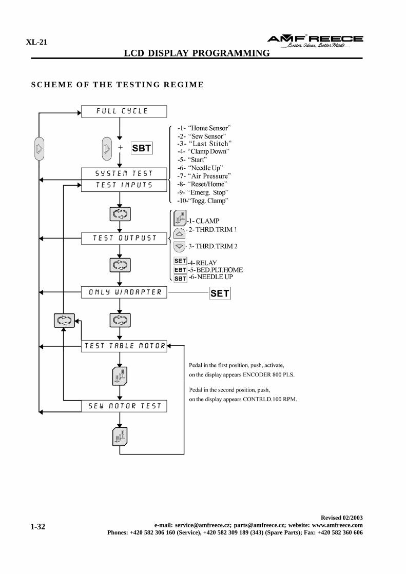
A program is available to test the major input functions, synchronizer, and encoder for correctoperation. To access the test program:
Press the and push-buttons.
Input tests
When the message SYSTEM TEST is displayed, the following may be tested:Needle positionStart pedalHome and sew sensors
With the machine in the home position, the display reads “1-HOMESENSOR”, indicating the processor isreceiving a signal from the home sensor and the table is in the home position.
Note: Any other message indicates a home sensor malfunction.Note: Only one function may be displayed, if two signals are being received the signal with the highestpriority will be displayed.
The order of priorities:-1- Home Senor-2- Sew Sensor-3- Last Stitch-4- Clamp Down-5- Start-6- Needle Up-7- Air Pressure-8- Reset/Home-9- Emerg. Stop-10- Togg. Clamp
Home and Sew Sensor Testing
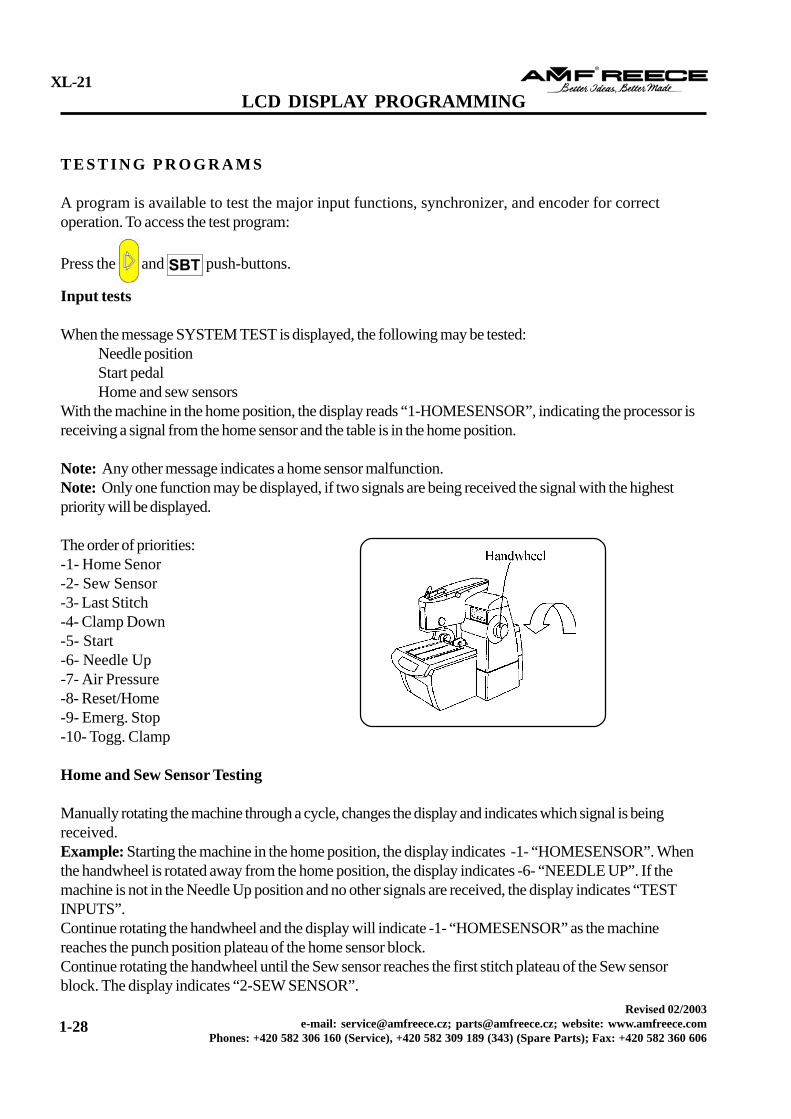
Manually rotating the machine through a cycle, changes the display and indicates which signal is beingreceived.Example: Starting the machine in the home position, the display indicates -1- “HOMESENSOR”. Whenthe handwheel is rotated away from the home position, the display indicates -6- “NEEDLE UP”. If themachine is not in the Needle Up position and no other signals are received, the display indicates “TESTINPUTS”.Continue rotating the handwheel and the display will indicate -1- “HOMESENSOR” as the machinereaches the punch position plateau of the home sensor block.Continue rotating the handwheel until the Sew sensor reaches the first stitch plateau of the Sew sensorblock. The display indicates “2-SEW SENSOR”.
Testing the Clamp Down Switch and the Start Treadle
Use the handwheel to rotate the machine manually until the display message reads “6-NEEDLE UP” or “TESTINPUTS”.Lightly toe the Start treadle to the first position, until the message reads “4-CLAMP DOWN”.Fully toe the START treadle. The message will read “5-START”.
Testing the buttons of the control panel
Push the white button “Home position” - on the display appears -8- RESET/HOME.Push the black button, on the display appears -10- Togg.Clamp.Push the red button Emergency Stop, on the display appears -9- Emerg. Stop.
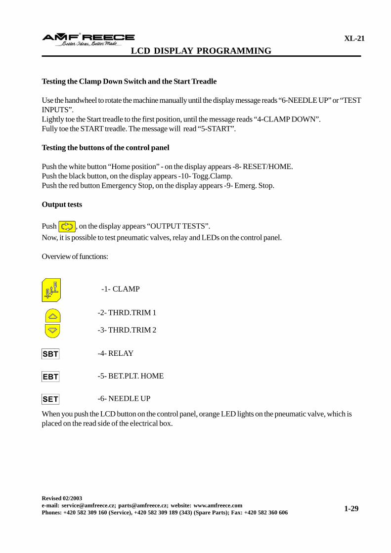
Output tests
Push , on the display appears “OUTPUT TESTS”.Now, it is possible to test pneumatic valves, relay and LEDs on the control panel.
Overview of functions:
-4- RELAY
-5- BET.PLT. HOME
-6- NEEDLE UP
-1- CLAMP
-2- THRD.TRIM 1
-3- THRD.TRIM 2
When you push the LCD button on the control panel, orange LED lights on the pneumatic valve, which isplaced on the read side of the electrical box.
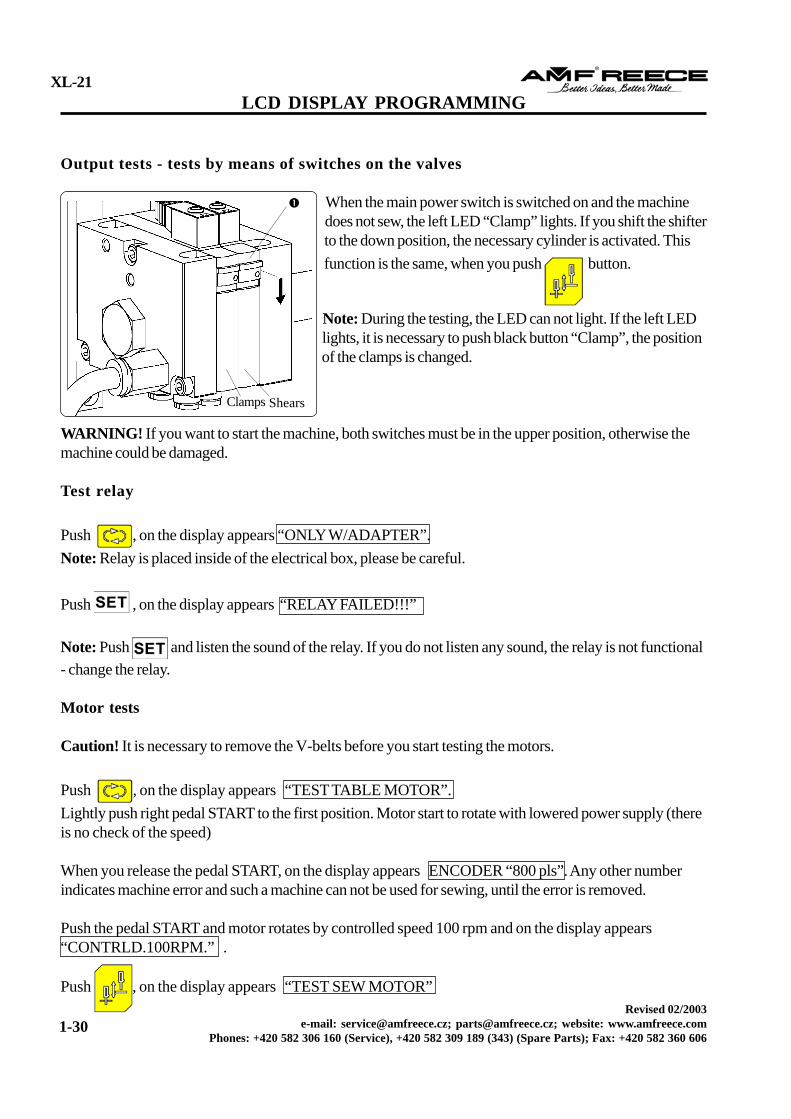
Output tests - tests by means of switches on the valves
When the main power switch is switched on and the machinedoes not sew, the left LED “Clamp” lights. If you shift the shifterto the down position, the necessary cylinder is activated. Thisfunction is the same, when you push button.
Note: During the testing, the LED can not light. If the left LEDlights, it is necessary to push black button “Clamp”, the positionof the clamps is changed.
WARNING! If you want to start the machine, both switches must be in the upper position, otherwise themachine could be damaged.
Test relay
Push , on the display appears “ONLY W/ADAPTER”.Note: Relay is placed inside of the electrical box, please be careful.
Push , on the display appears “RELAY FAILED!!!”
Note: Push and listen the sound of the relay. If you do not listen any sound, the relay is not functional- change the relay.
Motor tests
Caution! It is necessary to remove the V-belts before you start testing the motors.
Push , on the display appears “TEST TABLE MOTOR”.Lightly push right pedal START to the first position. Motor start to rotate with lowered power supply (thereis no check of the speed)
When you release the pedal START, on the display appears ENCODER “800 pls”. Any other numberindicates machine error and such a machine can not be used for sewing, until the error is removed.
Push the pedal START and motor rotates by controlled speed 100 rpm and on the display appears“CONTRLD.100RPM.” .
Note: If you want to move from the “Operating Mode” to the regime Motor Tests, push ,
together and 3 times .Process for this test is the same as previous motor test.
Push for re-entry to the programing regime.
R E S E T PA R A M E T E R R E N E WA L
Caution! Annul the program in memory, which is set from producer.
Switch off the main power switch .
Push , and together.
When all three buttons are pushed, switch on the main power switch.Display will change from “PUSH SET” to “FOR SET” .
Push and hold the button during 10 cycles. On the display appears “PROGRAMMING” .
Note: If the button is not pushed during 10 cycles, program moves to the main menu without“MASTER RESET”.
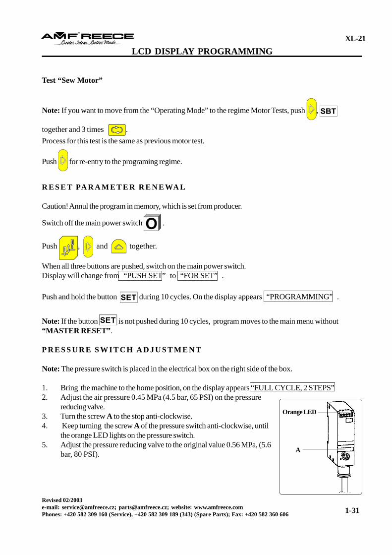
P R E S S U R E S W I T C H A D J U S T M E N T
Note: The pressure switch is placed in the electrical box on the right side of the box.
1. Bring the machine to the home position, on the display appears “FULL CYCLE, 2 STEPS”2. Adjust the air pressure 0.45 MPa (4.5 bar, 65 PSI) on the pressure
reducing valve.3. Turn the screw A to the stop anti-clockwise.4. Keep turning the screw A of the pressure switch anti-clockwise, until
the orange LED lights on the pressure switch.5. Adjust the pressure reducing valve to the original value 0.56 MPa, (5.6
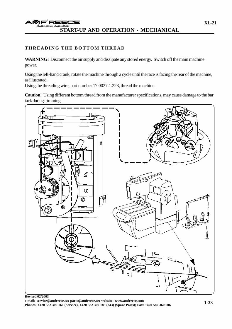
WARNING! Disconnect the air supply and dissipate any stored energy. Switch off the main machinepower.
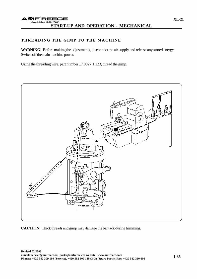
Using the left-hand crank, rotate the machine through a cycle until the race is facing the rear of the machine,as illustrated.Using the threading wire, part number 17.0027.1.223, thread the machine.
Caution! Using different bottom thread from the manufacturer specifications, may cause damage to the bartack during trimming.
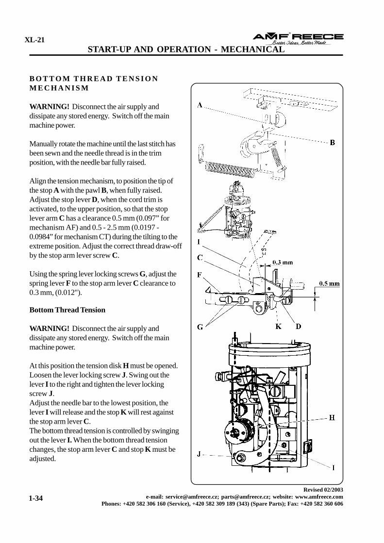
WARNING! Disconnect the air supply anddissipate any stored energy. Switch off the mainmachine power.
At this position the tension disk H must be opened.Loosen the lever locking screw J. Swing out thelever I to the right and tighten the lever lockingscrew J.Adjust the needle bar to the lowest position, thelever I will release and the stop K will rest againstthe stop arm lever C.The bottom thread tension is controlled by swingingout the lever I. When the bottom thread tensionchanges, the stop arm lever C and stop K must beadjusted.
B O T T O M T H R E A D T E N S I O NM E C H A N I S M
WARNING! Disconnect the air supply anddissipate any stored energy. Switch off the mainmachine power.
Manually rotate the machine until the last stitch hasbeen sewn and the needle thread is in the trimposition, with the needle bar fully raised.
Align the tension mechanism, to position the tip ofthe stop A with the pawl B, when fully raised.Adjust the stop lever D, when the cord trim isactivated, to the upper position, so that the stoplever arm C has a clearance 0.5 mm (0.097” formechanism AF) and 0.5 - 2.5 mm (0.0197 -0.0984” for mechanism CT) during the tilting to theextreme position. Adjust the correct thread draw-offby the stop arm lever screw C.
Using the spring lever locking screws G, adjust thespring lever F to the stop arm lever C clearance to0.3 mm, (0.012").
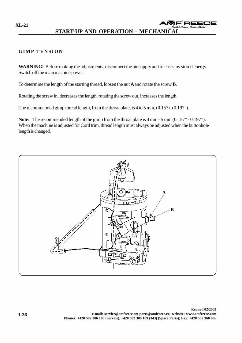
WARNING! Before making the adjustments, disconnect the air supply and release any stored energy.Switch off the main machine power.
To determine the length of the starting thread, loosen the nut A and rotate the screw B.
Rotating the screw in, decreases the length, rotating the screw out, increases the length.
The recommended gimp thread length, from the throat plate, is 4 to 5 mm, (0.157 to 0.197").
Note: The recommended length of the gimp from the throat plate is 4 mm - 5 mm (0.157” - 0.197”).When the machine is adjusted for Cord trim, thread length must always be adjusted when the buttonholelength is changed.
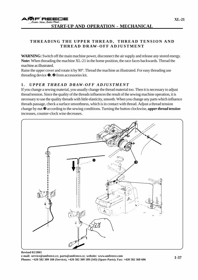
T H R E A D I N G T H E U P P E R T H R E A D , T H R E A D T E N S I O N A N DT H R E A D D R AW - O F F A D J U S T M E N T
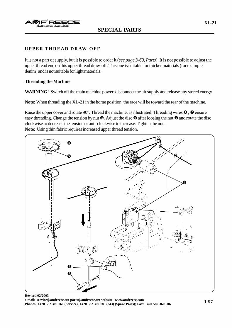
WARNING: Switch off the main machine power, disconnect the air supply and release any stored energy.Note: When threading the machine XL-21 in the home position, the race faces backwards. Thread themachine as illustrated.Raise the upper cover and rotate it by 90°. Thread the machine as illustrated. For easy threading usethreading device , from accessories kit.
1 . U P P E R T H R E A D D R AW- O F F A D J U S T M E N TIf you change a sewing material, you usually change the thread material too. Then it is necessary to adjustthread tension. Since the quality of the threads influences the result of the sewing machine operation, it isnecessary to use the quality threads with little elasticity, smooth. When you change any parts which influencethreads passage, check a surface smoothness, which is in contact with thread. Adjust a thread tensionchange by nut according to the sewing conditions. Turning the button clockwise, upper thread tensionincreases, counter-clock wise decreases.
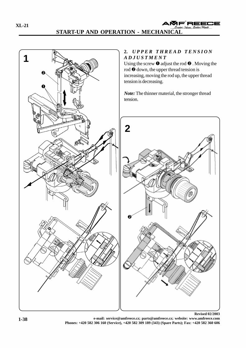
2. U P P E R T H R E A D T E N S I O NA D J U S T M E N TUsing the screw adjust the rod . Moving therod down, the upper thread tension isincreasing, moving the rod up, the upper threadtension is decreasing.
Note: The thinner material, the stronger threadtension.
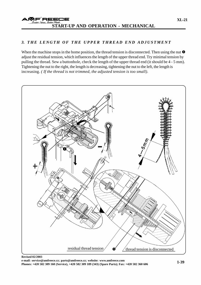
3. T H E L E N G T H O F T H E U P P E R T H R E A D E N D A D J U S T M E N T
When the machine stops in the home position, the thread tension is disconnected. Then using the nut adjust the residual tension, which influences the length of the upper thread end. Try minimal tension bypulling the thread. Sew a buttonhole, check the length of the upper thread end (it should be 4 - 5 mm).Tightening the nut to the right, the length is decreasing, tightening the nut to the left, the length isincreasing. ( If the thread is not trimmed, the adjusted tension is too small).
START-UP AND OPERATION - MECHANICAL
residual thread tension thread tension is disconnected
The movable plastic needle guard is located on the front sideof the head cover.
Note: Before installing the guard, remove the clamp plates.
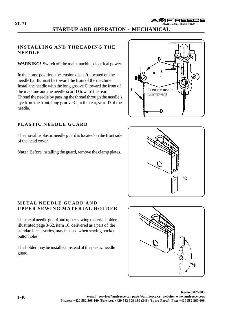
I N S TA L L I N G A N D T H R E A D I N G T H EN E E D L E
WARNING! Switch off the main machine electrical power.
In the home position, the tension disks A, located on theneedle bar B, must be toward the front of the machine.Install the needle with the long groove C toward the front ofthe machine and the needle scarf D toward the rear.Thread the needle by passing the thread through the needle’seye from the front, long groove C, to the rear, scarf D of theneedle.
Insert the needlefully upward
M E TA L N E E D L E G U A R D A N DU P P E R S E W I N G M AT E R I A L H O L D E R
The metal needle guard and upper sewing material holder,illustrated page 3-62, item 16, delivered as a part of thestandard accessories, may be used when sewing pocketbuttonholes.
The holder may be installed, instead of the plastic needleguard.
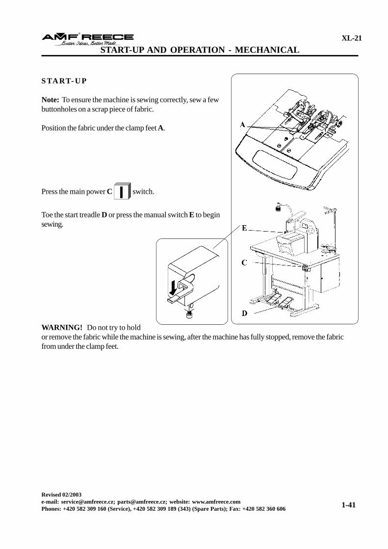
Note: To ensure the machine is sewing correctly, sew a fewbuttonholes on a scrap piece of fabric.
Position the fabric under the clamp feet A.
Press the main power C switch.
Toe the start treadle D or press the manual switch E to beginsewing.
WARNING! Do not try to holdor remove the fabric while the machine is sewing, after the machine has fully stopped, remove the fabricfrom under the clamp feet.
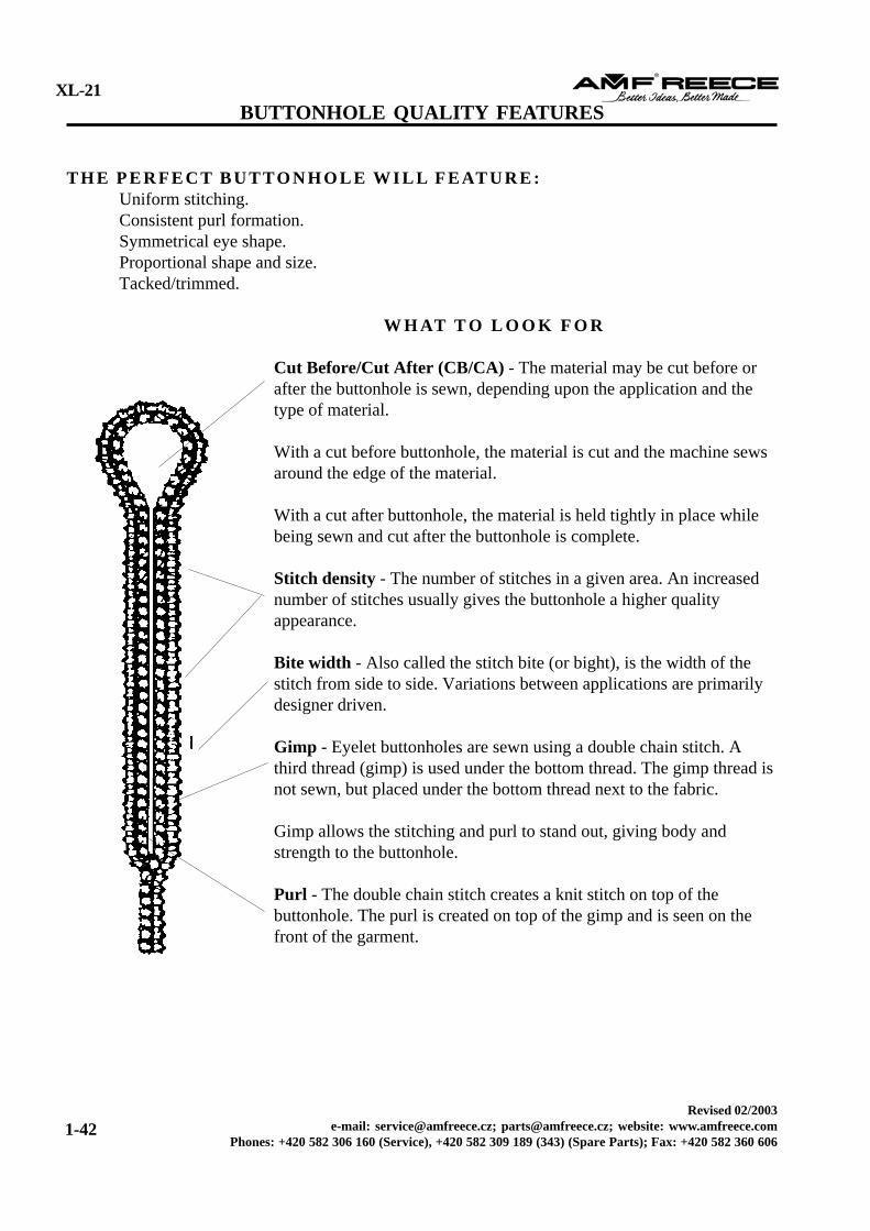
T H E P E R F E C T B U T TO N H O L E W I L L F E AT U R E :Uniform stitching.Consistent purl formation.Symmetrical eye shape.Proportional shape and size.Tacked/trimmed.
W H AT T O L O O K F O R
Cut Before/Cut After (CB/CA) - The material may be cut before orafter the buttonhole is sewn, depending upon the application and thetype of material.
With a cut before buttonhole, the material is cut and the machine sewsaround the edge of the material.
With a cut after buttonhole, the material is held tightly in place whilebeing sewn and cut after the buttonhole is complete.
Stitch density - The number of stitches in a given area. An increasednumber of stitches usually gives the buttonhole a higher qualityappearance.
Bite width - Also called the stitch bite (or bight), is the width of thestitch from side to side. Variations between applications are primarilydesigner driven.
Gimp - Eyelet buttonholes are sewn using a double chain stitch. Athird thread (gimp) is used under the bottom thread. The gimp thread isnot sewn, but placed under the bottom thread next to the fabric.
Gimp allows the stitching and purl to stand out, giving body andstrength to the buttonhole.
Purl - The double chain stitch creates a knit stitch on top of thebuttonhole. The purl is created on top of the gimp and is seen on thefront of the garment.
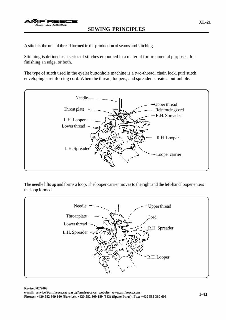
A stitch is the unit of thread formed in the production of seams and stitching.
Stitching is defined as a series of stitches embodied in a material for ornamental purposes, forfinishing an edge, or both.
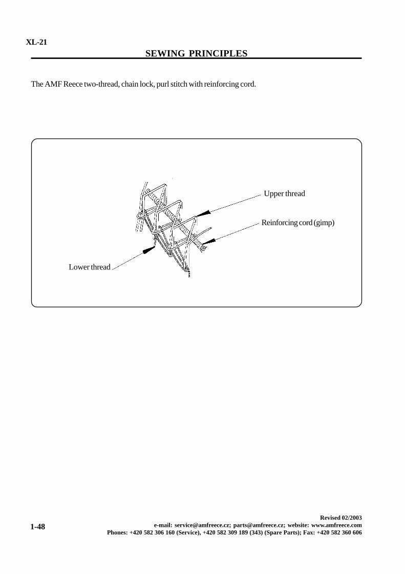
The type of stitch used in the eyelet buttonhole machine is a two-thread, chain lock, purl stitchenveloping a reinforcing cord. When the thread, loopers, and spreaders create a buttonhole:
The needle lifts up and forms a loop. The looper carrier moves to the right and the left-hand looper entersthe loop formed.
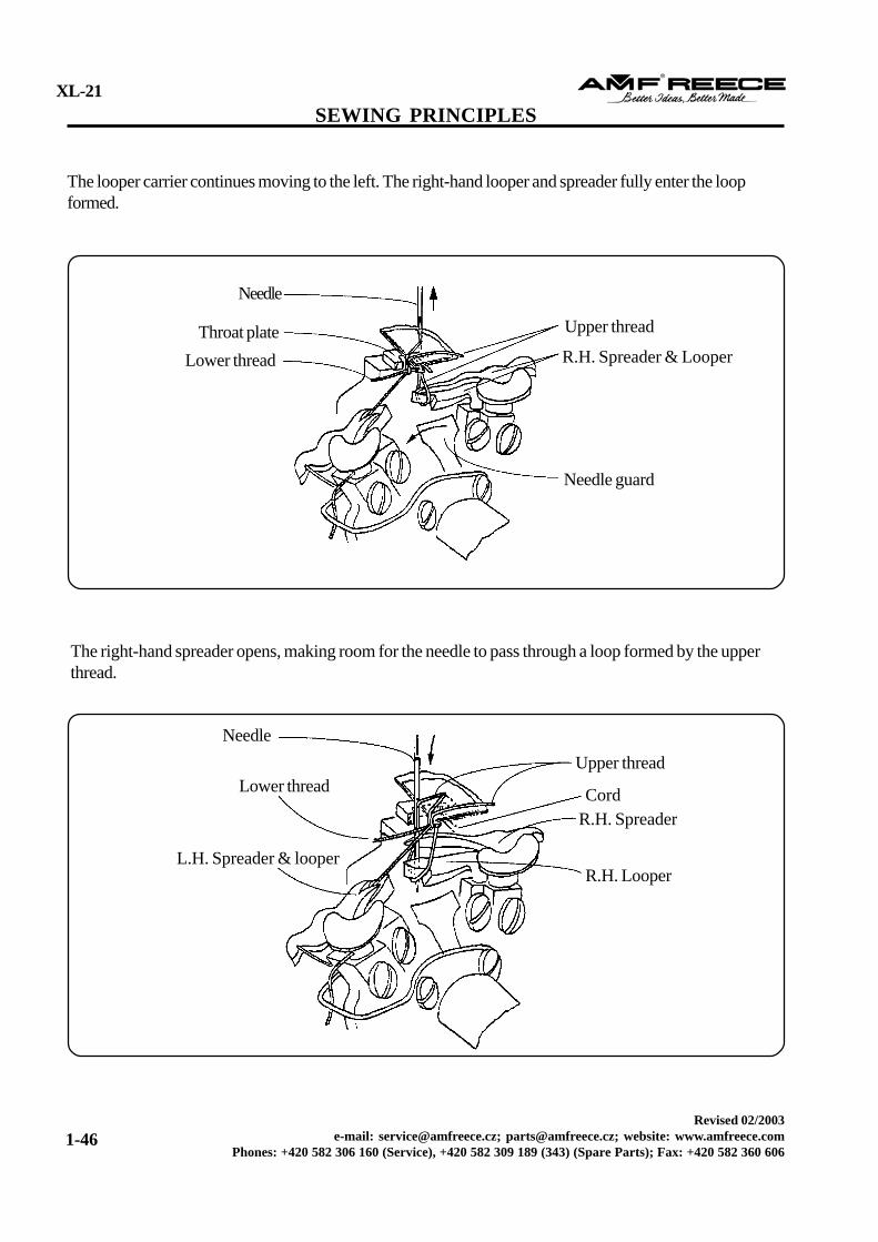
The looper carrier continues moving to the right, carrying the lower thread, the left-hand looper, and thespreader, fully into the loop formed.
The left-hand spreader opens, making room for the needle to pass through the loop formed by the lowerthread. This penetration, allows the needle to encompasses the cord.
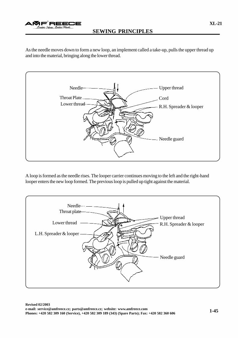
As the needle moves down to form a new loop, an implement called a take-up, pulls the upper thread upand into the material, bringing along the lower thread.
A loop is formed as the needle rises. The looper carrier continues moving to the left and the right-handlooper enters the new loop formed. The previous loop is pulled up tight against the material.
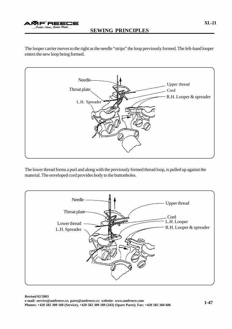
The looper carrier moves to the right as the needle “strips” the loop previously formed. The left-hand looperenters the new loop being formed.
The lower thread forms a purl and along with the previously formed thread loop, is pulled up against thematerial. The enveloped cord provides body to the buttonholes.
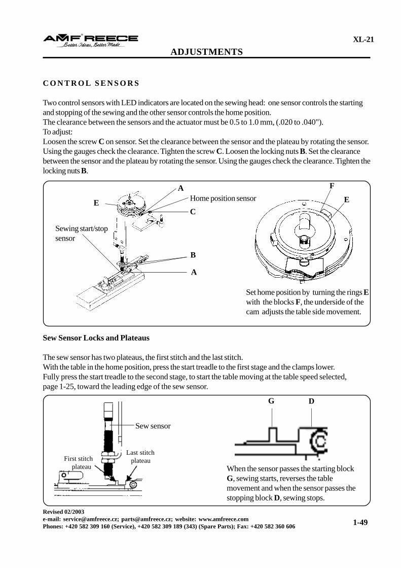
Two control sensors with LED indicators are located on the sewing head: one sensor controls the startingand stopping of the sewing and the other sensor controls the home position.The clearance between the sensors and the actuator must be 0.5 to 1.0 mm, (.020 to .040").To adjust:Loosen the screw C on sensor. Set the clearance between the sensor and the plateau by rotating the sensor.Using the gauges check the clearance. Tighten the screw C. Loosen the locking nuts B. Set the clearancebetween the sensor and the plateau by rotating the sensor. Using the gauges check the clearance. Tighten thelocking nuts B.
Sew Sensor Locks and Plateaus
The sew sensor has two plateaus, the first stitch and the last stitch.With the table in the home position, press the start treadle to the first stage and the clamps lower.Fully press the start treadle to the second stage, to start the table moving at the table speed selected,page 1-25, toward the leading edge of the sew sensor.
F
E
Set home position by turning the rings Ewith the blocks F, the underside of thecam adjusts the table side movement.
Home position sensor
B
A
Sewing start/stopsensor
C
A
E
First stitch plateau
Last stitch plateau
Sew sensor
G D
When the sensor passes the starting blockG, sewing starts, reverses the tablemovement and when the sensor passes thestopping block D, sewing stops.
WARNING! Before making adjustments, disconnect the air supply and dissipate any stored energy.When the table reaches the leading edge, the speed decreases to half the set parameter. At the trailing edgeof the first stitch plateau, table motion stops and the sew motor starts. As the machine begins to sew, theleading edge of the last stitch plateau will be ignored. As sewing continues, the trailing edge of the last stitchplateau starts the final stitch count to complete the buttonhole.
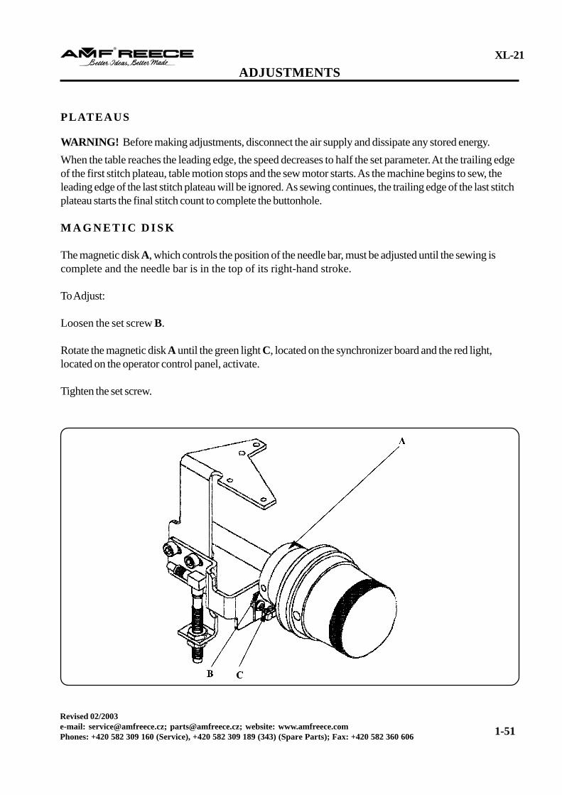
M A G N E T I C D I S K
The magnetic disk A, which controls the position of the needle bar, must be adjusted until the sewing iscomplete and the needle bar is in the top of its right-hand stroke.
To Adjust:
Loosen the set screw B.
Rotate the magnetic disk A until the green light C, located on the synchronizer board and the red light,located on the operator control panel, activate.
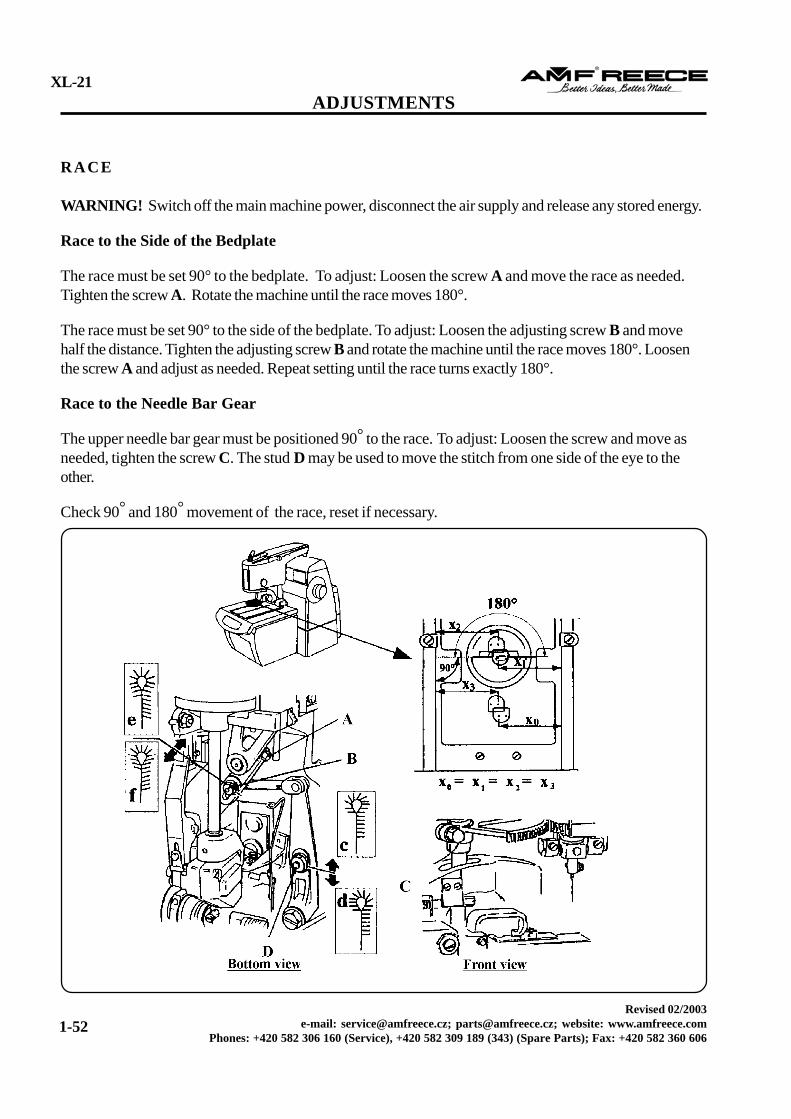
WARNING! Switch off the main machine power, disconnect the air supply and release any stored energy.
Race to the Side of the Bedplate
The race must be set 90° to the bedplate. To adjust: Loosen the screw A and move the race as needed.Tighten the screw A. Rotate the machine until the race moves 180°.
The race must be set 90° to the side of the bedplate. To adjust: Loosen the adjusting screw B and movehalf the distance. Tighten the adjusting screw B and rotate the machine until the race moves 180°. Loosenthe screw A and adjust as needed. Repeat setting until the race turns exactly 180°.
Race to the Needle Bar Gear
The upper needle bar gear must be positioned 90° to the race. To adjust: Loosen the screw and move asneeded, tighten the screw C. The stud D may be used to move the stitch from one side of the eye to theother.
Check 90° and 180° movement of the race, reset if necessary.
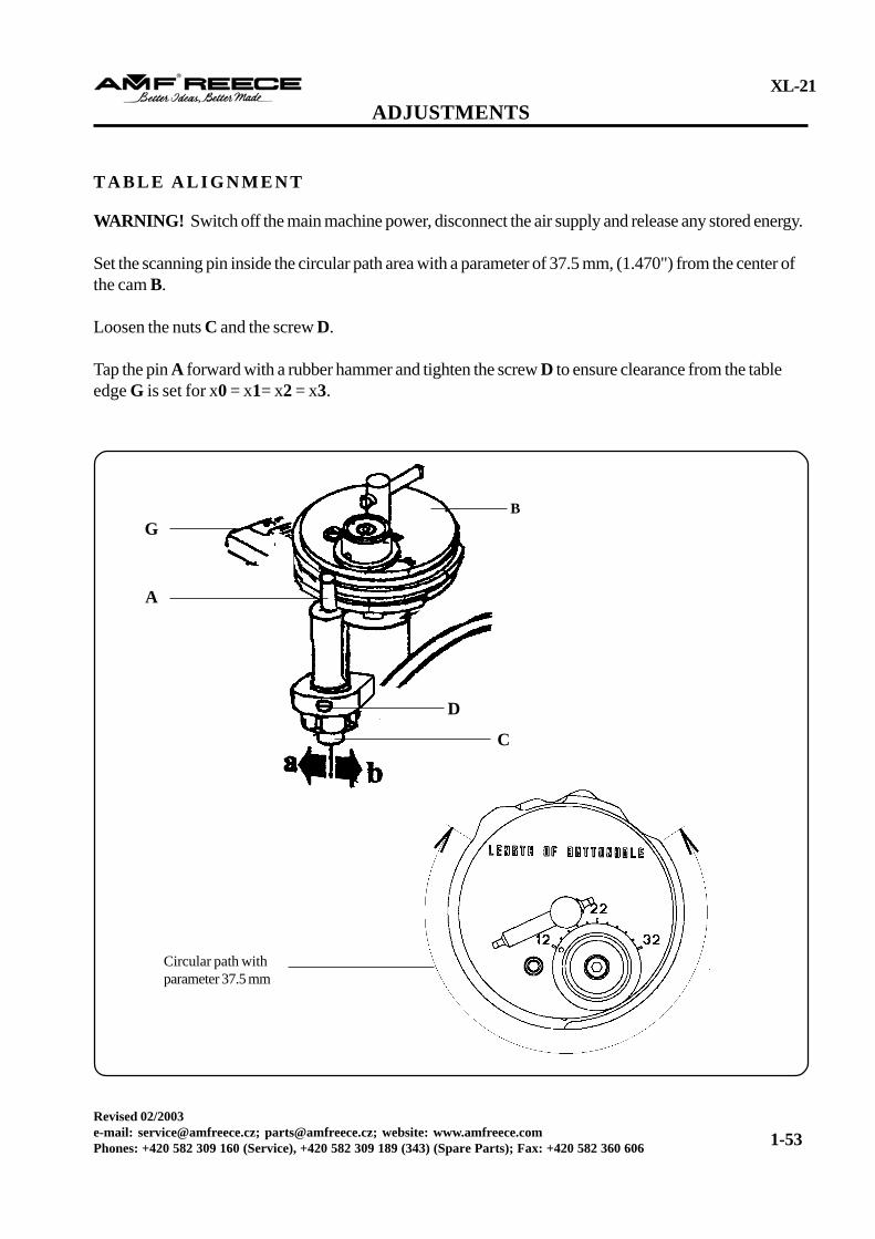
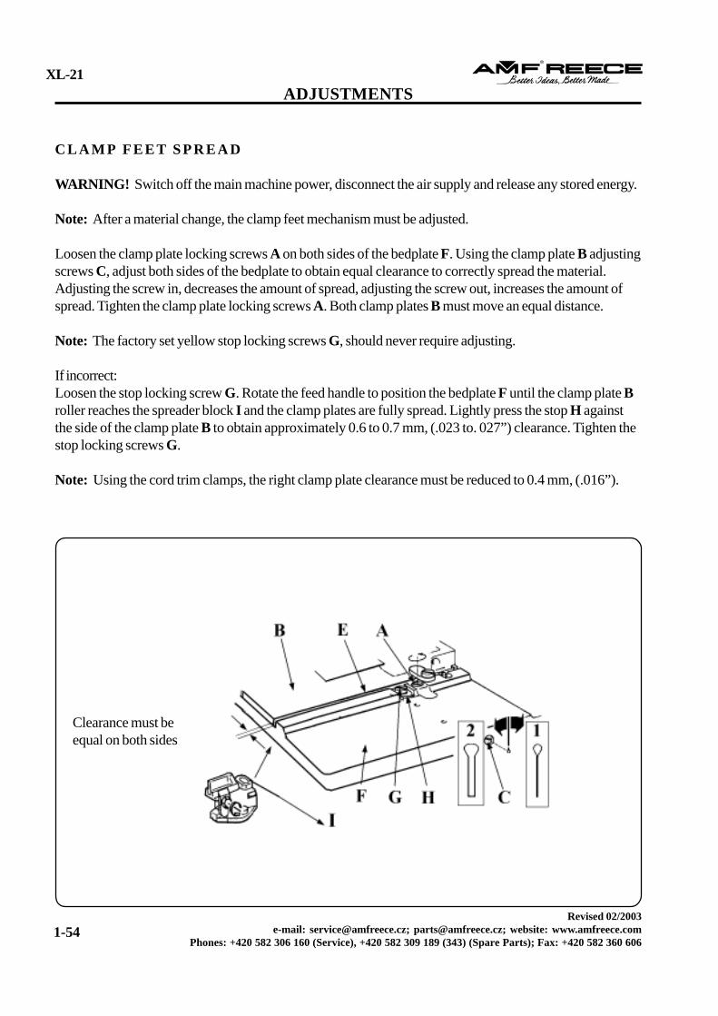
WARNING! Switch off the main machine power, disconnect the air supply and release any stored energy.
Note: After a material change, the clamp feet mechanism must be adjusted.
Loosen the clamp plate locking screws A on both sides of the bedplate F. Using the clamp plate B adjustingscrews C, adjust both sides of the bedplate to obtain equal clearance to correctly spread the material.Adjusting the screw in, decreases the amount of spread, adjusting the screw out, increases the amount ofspread. Tighten the clamp plate locking screws A. Both clamp plates B must move an equal distance.
Note: The factory set yellow stop locking screws G, should never require adjusting.
If incorrect:Loosen the stop locking screw G. Rotate the feed handle to position the bedplate F until the clamp plate Broller reaches the spreader block I and the clamp plates are fully spread. Lightly press the stop H againstthe side of the clamp plate B to obtain approximately 0.6 to 0.7 mm, (.023 to. 027”) clearance. Tighten thestop locking screws G.
Note: Using the cord trim clamps, the right clamp plate clearance must be reduced to 0.4 mm, (.016”).
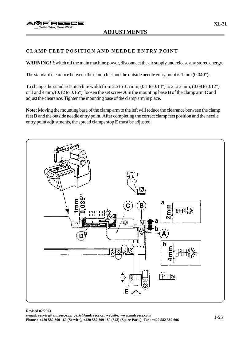
C L A M P F E E T P O S I T I O N A N D N E E D L E E N T RY P O I N T
WARNING! Switch off the main machine power, disconnect the air supply and release any stored energy.
The standard clearance between the clamp feet and the outside needle entry point is 1 mm (0.040").
To change the standard stitch bite width from 2.5 to 3.5 mm, (0.1 to 0.14") to 2 to 3 mm, (0.08 to 0.12")or 3 and 4 mm, (0.12 to 0.16"), loosen the set screw A in the mounting base B of the clamp arm C andadjust the clearance. Tighten the mounting base of the clamp arm in place.
Note: Moving the mounting base of the clamp arm to the left will reduce the clearance between the clampfeet D and the outside needle entry point. After completing the correct clamp feet position and the needleentry point adjustments, the spread clamps stop E must be adjusted.
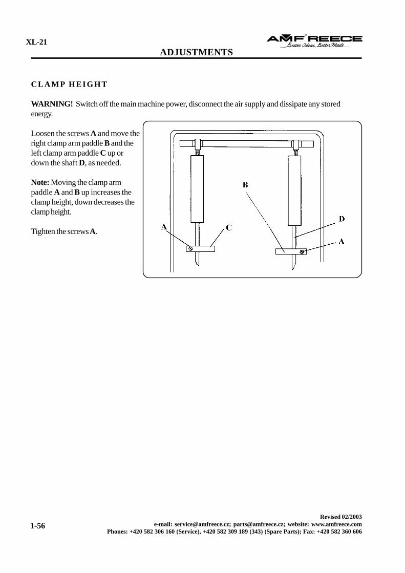
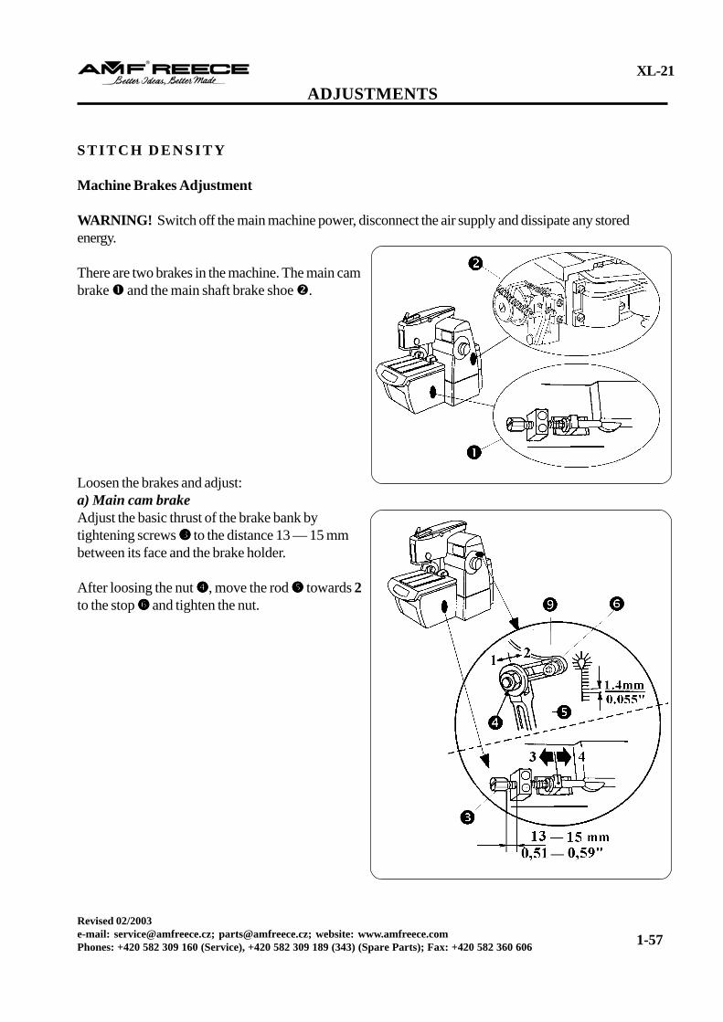
WARNING! Switch off the main machine power, disconnect the air supply and dissipate any storedenergy.
There are two brakes in the machine. The main cambrake and the main shaft brake shoe .
Loosen the brakes and adjust:a) Main cam brakeAdjust the basic thrust of the brake bank bytightening screws to the distance 13 — 15 mmbetween its face and the brake holder.
After loosing the nut , move the rod towards 2to the stop and tighten the nut.
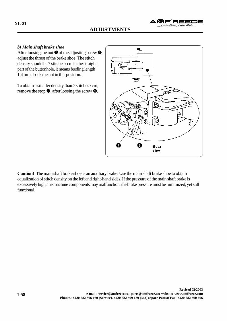
b) Main shaft brake shoeAfter loosing the nut of the adjusting screw ,adjust the thrust of the brake shoe. The stitchdensity should be 7 stitches / cm in the straightpart of the buttonhole, it means feeding length1.4 mm. Lock the nut in this position.
To obtain a smaller density than 7 stitches / cm,remove the stop , after loosing the screw .
Caution! The main shaft brake shoe is an auxiliary brake. Use the main shaft brake shoe to obtainequalization of stitch density on the left and right-hand sides. If the pressure of the main shaft brake isexcessively high, the machine components may malfunction, the brake pressure must be minimized, yet stillfunctional.
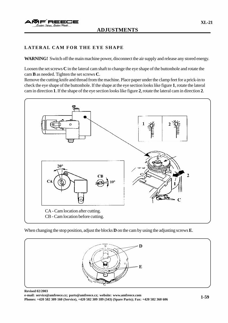
WARNING! Switch off the main machine power, disconnect the air supply and release any stored energy.
Loosen the set screws C in the lateral cam shaft to change the eye shape of the buttonhole and rotate thecam B as needed. Tighten the set screws C.Remove the cutting knife and thread from the machine. Place paper under the clamp feet for a prick-in tocheck the eye shape of the buttonhole. If the shape at the eye section looks like figure 1, rotate the lateralcam in direction 1. If the shape of the eye section looks like figure 2, rotate the lateral cam in direction 2.
When changing the stop position, adjust the blocks D on the cam by using the adjusting screws E.
D
E
CA - Cam location after cutting.CB - Cam location before cutting.
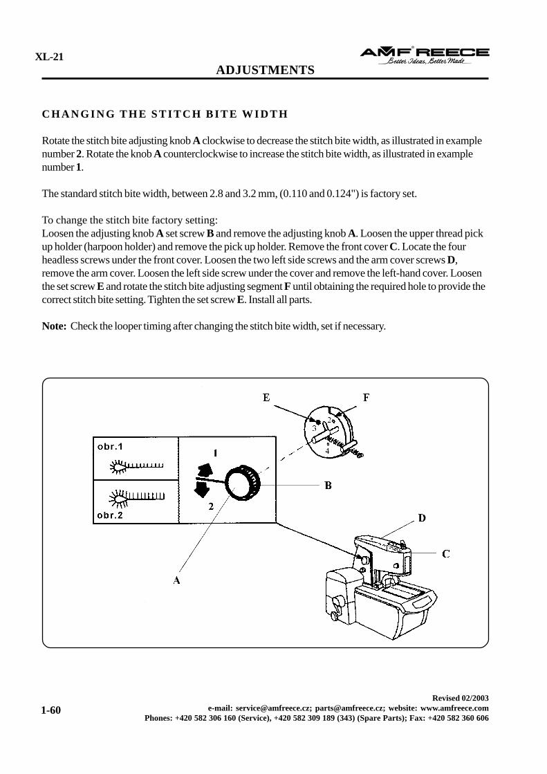
C H A N G I N G T H E S T I T C H B I T E W I D T H
Rotate the stitch bite adjusting knob A clockwise to decrease the stitch bite width, as illustrated in examplenumber 2. Rotate the knob A counterclockwise to increase the stitch bite width, as illustrated in examplenumber 1.
The standard stitch bite width, between 2.8 and 3.2 mm, (0.110 and 0.124") is factory set.
To change the stitch bite factory setting:Loosen the adjusting knob A set screw B and remove the adjusting knob A. Loosen the upper thread pickup holder (harpoon holder) and remove the pick up holder. Remove the front cover C. Locate the fourheadless screws under the front cover. Loosen the two left side screws and the arm cover screws D,remove the arm cover. Loosen the left side screw under the cover and remove the left-hand cover. Loosenthe set screw E and rotate the stitch bite adjusting segment F until obtaining the required hole to provide thecorrect stitch bite setting. Tighten the set screw E. Install all parts.
Note: Check the looper timing after changing the stitch bite width, set if necessary.
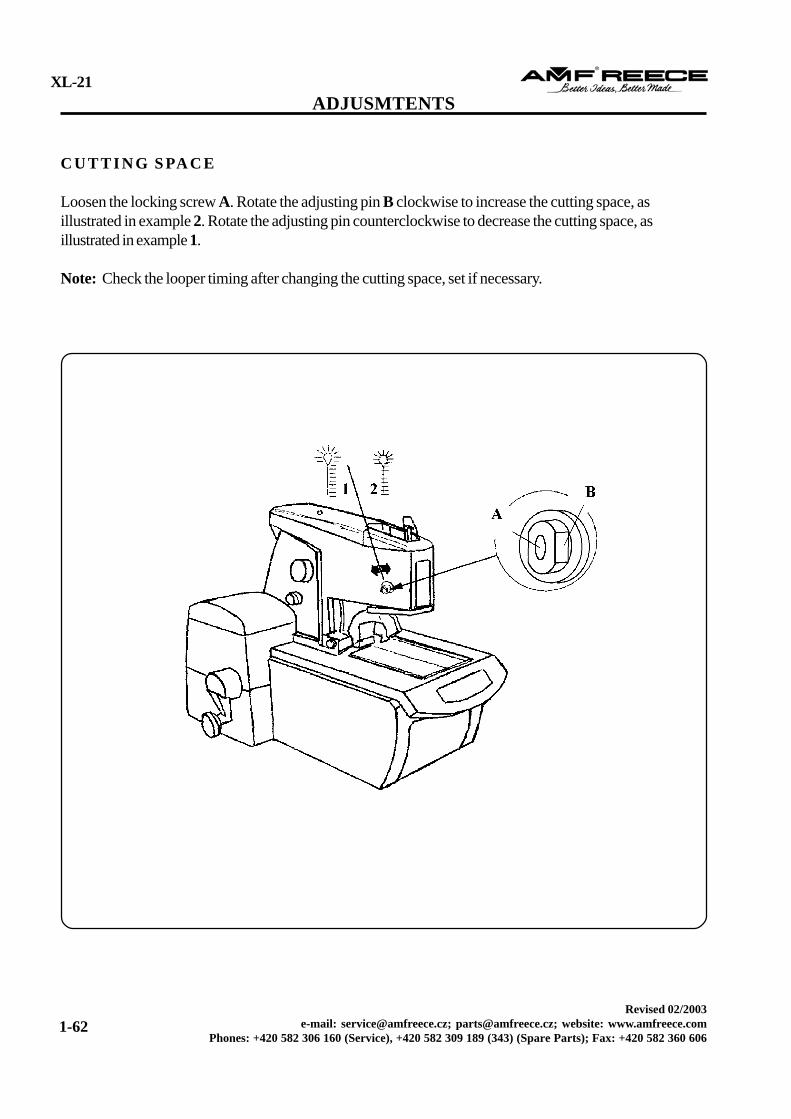
Loosen the locking screw A. Rotate the adjusting pin B clockwise to increase the cutting space, asillustrated in example 2. Rotate the adjusting pin counterclockwise to decrease the cutting space, asillustrated in example 1.
Note: Check the looper timing after changing the cutting space, set if necessary.
B U T T O N H O L E S H A P E A N D T H E I N S I D E C U T L E N G T H
The XL-21 eyelet buttonhole machine is supplied with the capability of producing adjustable fly and cordtrim buttonholes.
Adjustable Fly
AF CB/CA RE, following only AF - with buttonhole lengths from 12 to 32 mm and upper thread trim.Cutting before or cutting after sewing. The buttonhole may be adjusted with the eye shapes (0/0; 2.5/4; 3/5;4/5; - width - height ratio), page 1-65.
Cord Trim
AF CB-CA RE , following CT - with buttonhole lengths of 16 - 22 mm, all threads are trimmed, (upper,bottom, and inserted gimp thread). Trimming of thin materials is only adjusted when the sewn buttonhole hasa eye shape of (0/0; 2.5/4; 3/5; 4/5; - width - height ratio), page 1-65.
The XL-21 eyelet buttonhole machine is supplied with the capability of producing variable eye shapes.
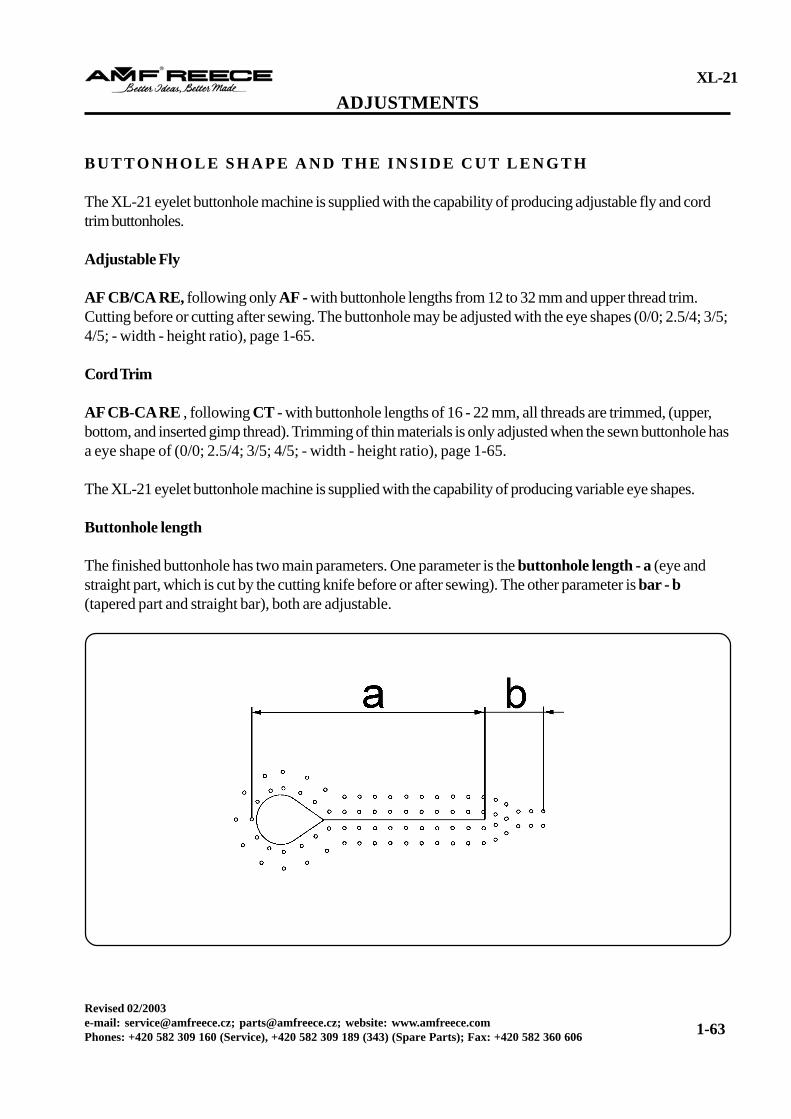
Buttonhole length
The finished buttonhole has two main parameters. One parameter is the buttonhole length - a (eye andstraight part, which is cut by the cutting knife before or after sewing). The other parameter is bar - b(tapered part and straight bar), both are adjustable.
E L E M E N T S F O R B U T T O N H O L E L E N G T H A D J U S T M E N T
Buttonhole length is adjusted by using two mechanical and one electronic element:1. The adjustable cam2. The adjustable pull rod dial3. The LCD display
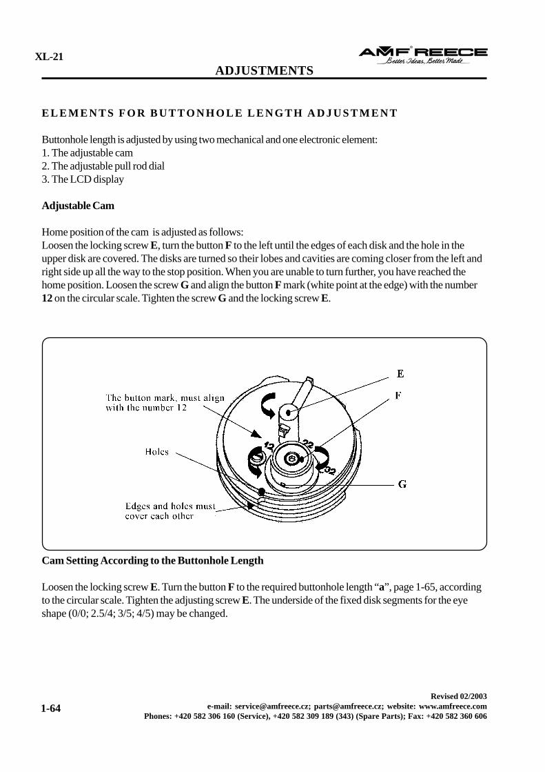
Adjustable Cam
Home position of the cam is adjusted as follows:Loosen the locking screw E, turn the button F to the left until the edges of each disk and the hole in theupper disk are covered. The disks are turned so their lobes and cavities are coming closer from the left andright side up all the way to the stop position. When you are unable to turn further, you have reached thehome position. Loosen the screw G and align the button F mark (white point at the edge) with the number12 on the circular scale. Tighten the screw G and the locking screw E.
Cam Setting According to the Buttonhole Length
Loosen the locking screw E. Turn the button F to the required buttonhole length “a”, page 1-65, accordingto the circular scale. Tighten the adjusting screw E. The underside of the fixed disk segments for the eyeshape (0/0; 2.5/4; 3/5; 4/5) may be changed.
Buttonhole 12-25 mm 26 mm 27 mm 28 mm 29 mm 30 mm 31 mm 32 mm length
Minimum bar length 3 mm 3 mm 3 mm 3 mm 3 mm 0 0 0 for appearance
Maximum bar length 7 mm 6 mm 5 mm 4 mm 3 mm 0 0 0
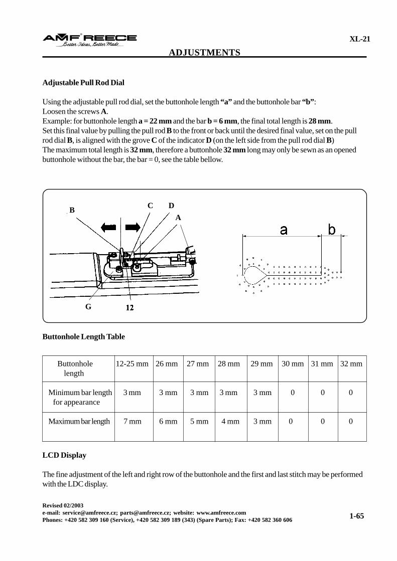
Adjustable Pull Rod Dial
Using the adjustable pull rod dial, set the buttonhole length “a” and the buttonhole bar “b”:Loosen the screws A.Example: for buttonhole length a = 22 mm and the bar b = 6 mm, the final total length is 28 mm.Set this final value by pulling the pull rod B to the front or back until the desired final value, set on the pullrod dial B, is aligned with the grove C of the indicator D (on the left side from the pull rod dial B)The maximum total length is 32 mm, therefore a buttonhole 32 mm long may only be sewn as an openedbuttonhole without the bar, the bar = 0, see the table bellow.
B C DA
G
Buttonhole Length Table
LCD Display
The fine adjustment of the left and right row of the buttonhole and the first and last stitch may be performedwith the LDC display.
All the variable parts for the AF adjustment are marked with a white color. The parts are:- LH clamp plate assembly- RH clamp plate assembly- Throat plate- Cutting steels in lengths 12-32 (only the selected set 12, 16, 19, 22, 26, 29 is delivered with the machine)- Knife with the large eye for cutting before sewing- Knife with the small eye for cutting after sewing- Straight knife for cutting the straight buttonhole- Segments for the eye shape 0/0; 2.5/4; 3/5; 4/5; segment 3.5 is already assembled in the machine, the other segments are delivered with the machine.
Caution! If the parts are changed for the parts marked with a blue color, the machine may be damaged.
When the parts are correctly installed, the buttonhole length adjustment may be performed according to thesteps in the “Buttonhole Shape and inside cut length” and “Elements for Buttonhole Length Adjustment”.There is only one exception from the description, the stop G must be turned 90° to allow free movement ofthe adjustable pull rod dial. The scale, 12 - 32 mm is marked with a white color on the pull rod dial.
Cord Trim
All the exchangeable parts for CT adjustment are marked by a blue color. The parts are following:- LH clamp plate assembly- RH clamp plate assembly- Throat plate- Cutting steels in lengths 16, 19 and 22- Shortened knife with the large eye for cutting before sewing- Shortened knife with the small eye for cutting after sewing- Shortened straight knife for cutting the straight buttonhole- Segments for the eye shape 0/0; 2.5/4; 3/5; 4/5; segment 3.5 is already assembled in the machine, another segments are part of delivery
Caution! If parts marked with the white color are incorrectly exchanged, machine damage may occur.
When the parts are correctly fixed, buttonhole length adjustment can be made according already describedsteps in “Buttonhole shape and inside cut length” and “Elements for Buttonhole Length Adjustment”. Thereis only one exception from the description, the stop G must be turned to prevent adjustable pull rod dial Bfrom free movement towards setting the longer buttonhole then 22 mm and bar 7 mm, so the total value 29mm. The scale 16 mm - 32 mm is marked by a blue color on the pull rod dial. If different setting from theabove described is made trim function is not functional or knives can contact needle and some parts wouldbe damaged.
WARNING! Switch off the main machine power, disconnect the air supply and release any stored energy.
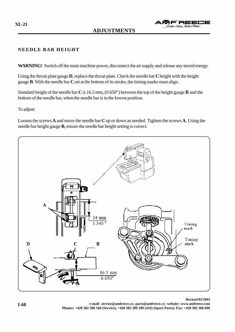
Using the throat plate gauge D, replace the throat plate. Check the needle bar C height with the heightgauge B. With the needle bar C set at the bottom of its stroke, the timing marks must align.
Standard height of the needle bar C is 16.5 mm, (0.650") between the top of the height gauge B and thebottom of the needle bar, when the needle bar is in the lowest position.
To adjust:
Loosen the screws A and move the needle bar C up or down as needed. Tighten the screws A. Using theneedle bar height gauge B, ensure the needle bar height setting is correct.
WARNING! Switch off the main machine power, disconnect the air supply and release any stored energy.
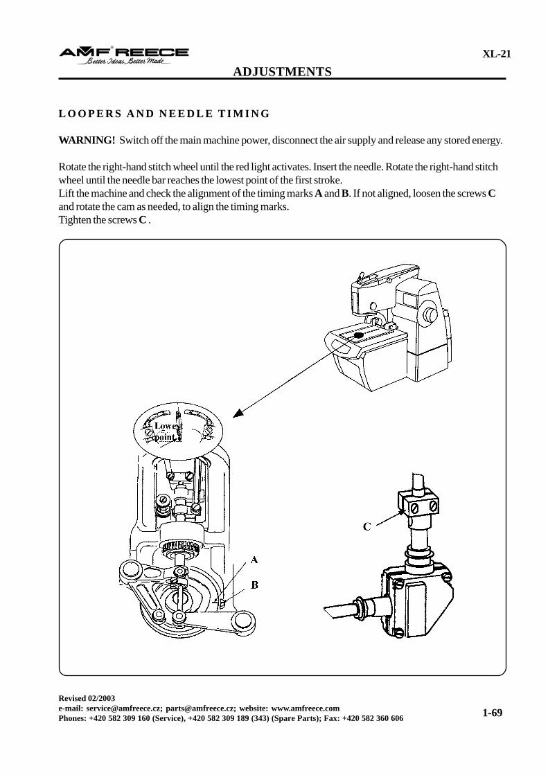
Rotate the right-hand stitch wheel until the red light activates. Insert the needle. Rotate the right-hand stitchwheel until the needle bar reaches the lowest point of the first stroke.Lift the machine and check the alignment of the timing marks A and B. If not aligned, loosen the screws Cand rotate the cam as needed, to align the timing marks.Tighten the screws C .
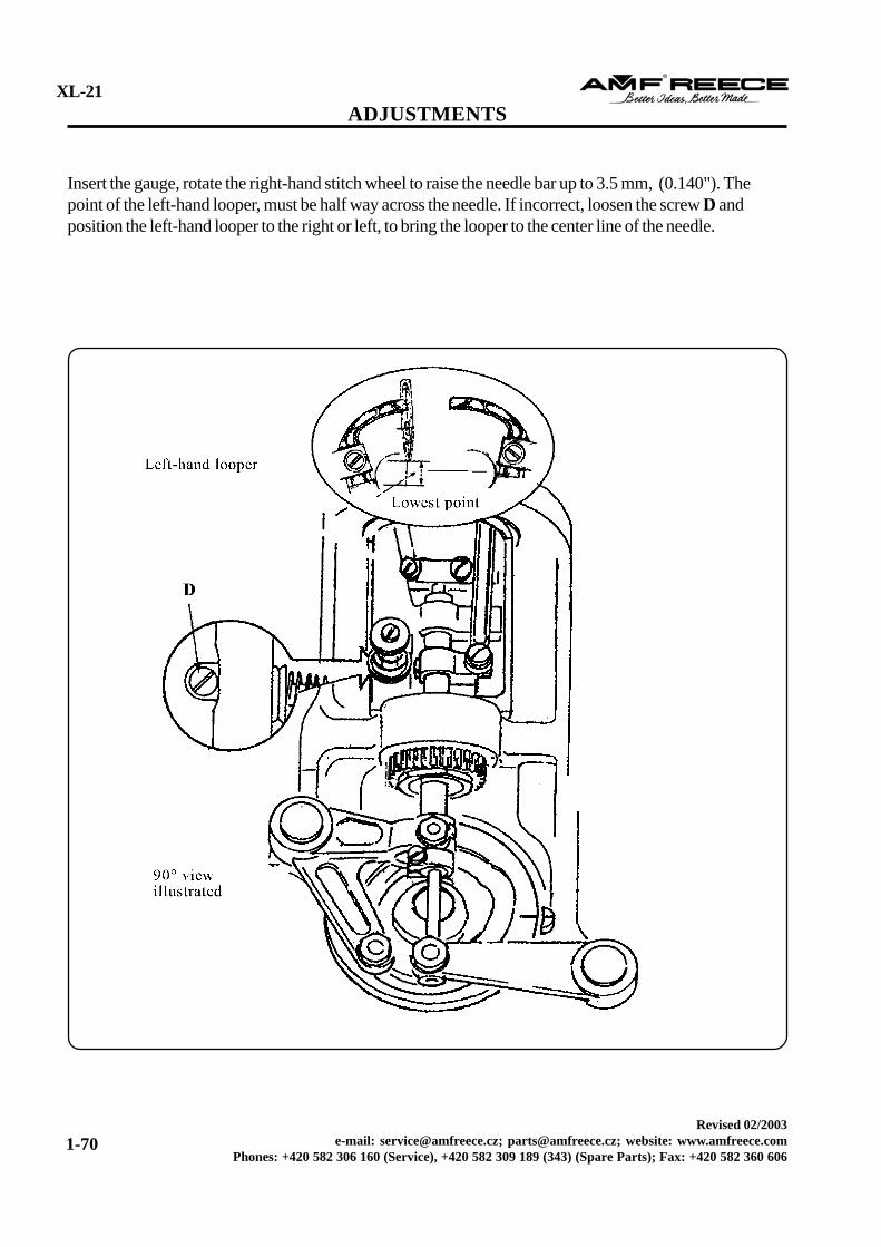
Insert the gauge, rotate the right-hand stitch wheel to raise the needle bar up to 3.5 mm, (0.140"). Thepoint of the left-hand looper, must be half way across the needle. If incorrect, loosen the screw D andposition the left-hand looper to the right or left, to bring the looper to the center line of the needle.
WARNING! Switch off the main machine power, disconnect the air supply and release any stored energy.
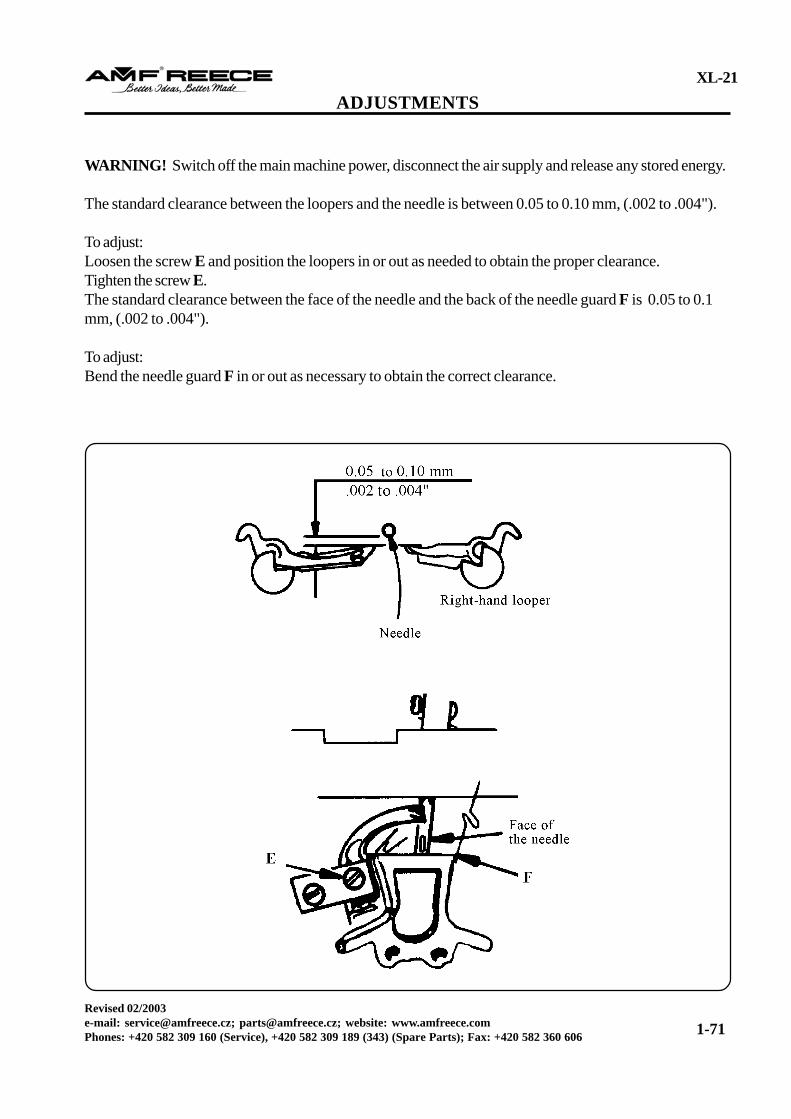
The standard clearance between the loopers and the needle is between 0.05 to 0.10 mm, (.002 to .004").
To adjust:Loosen the screw E and position the loopers in or out as needed to obtain the proper clearance.Tighten the screw E.The standard clearance between the face of the needle and the back of the needle guard F is 0.05 to 0.1mm, (.002 to .004").
To adjust:Bend the needle guard F in or out as necessary to obtain the correct clearance.
WARNING! Switch off the main machine power, disconnect the air supply and release any stored energy.
Rotate the left-hand crank until the needle bar is in the lowest point of the vibrator stroke. Insert the gauge,rotate the right-hand stitch wheel to move the needle bar up to 3.5 mm, (0.140"). The point of the right-hand looper must be halfway across the needle. If incorrect, repeat the setting.
CAUTION! When purchasing new loopers and spreaders, it is imperative only XL-21 AMF Reecedesigned parts be used for this machine. The part numbers are listed in the Parts Section of this manual.
WARNING! Switch off the main machine power, disconnect the air supply and release any stored energy.
Note: The factory set yellow screw A, should never need adjusting.
Note: Adjust until the spreaders open and close equally on the left and right without contacting the needle.
If incorrect:
Loosen the set screw A in the spreader crosshead B, located in the spreader spindle C. Rotate thespreader spindle, by holding the wrench on the flats on the bottom of the spindle, until obtaining the correctposition. Once the adjustment is correct, tighten the set screw A holding the crosshead B in place.
It is very important both the right-hand and left-hand spreaders are on e q u a l distance from the needle.
WARNING! Switch off the main machine power, disconnect the air supply and release any stored energy.
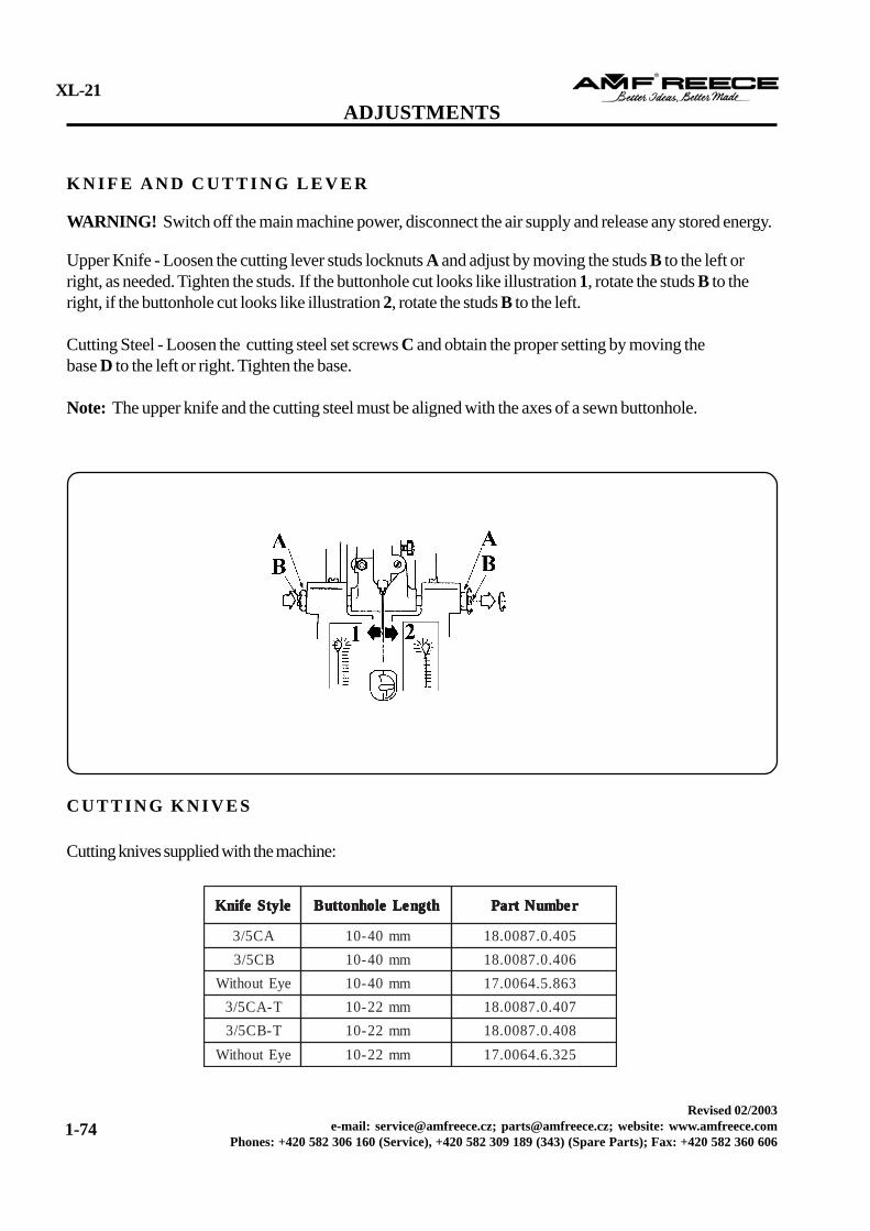
Upper Knife - Loosen the cutting lever studs locknuts A and adjust by moving the studs B to the left orright, as needed. Tighten the studs. If the buttonhole cut looks like illustration 1, rotate the studs B to theright, if the buttonhole cut looks like illustration 2, rotate the studs B to the left.
Cutting Steel - Loosen the cutting steel set screws C and obtain the proper setting by moving thebase D to the left or right. Tighten the base.
Note: The upper knife and the cutting steel must be aligned with the axes of a sewn buttonhole.
C H A N G I N G T H E K N I F E A N D T H E C U T T I N G S T E E L
Note: The cutting pressure must be adjusted when the cutting steel or the knife is replaced, or when thetype of fabric being sewn changes. The cutting steel varies according to the buttonhole length.
Caution! To obtain correct buttonhole cuts perform each step of the following procedure. Failure to followthese steps may cause knife breakage and possible machine damage.
WARNING! Switch off the main machine power, disconnect the air supply and release any stored energy.
Remove the knife G and the cutting steel H. Ensure the contact surface of the cutting lever J and the knifeholder are not damaged. Install the new cutting steel H. Install the new knife G against the stop I and lightlytighten the knife locking screw F. Manually lower the knife G against the cutting steel H to seat the knife Gin the holder and fully tighten the knife locking screw F. Manually position the cutting lever toward the knifeholder and ensure the knife G and the cutting steel H are correctly aligned. Decrease the cutting leverpressure by rotating the pressure adjusting screw E counterclockwise three revolutions. Position a piece ofpaper between the knife G and the cutting steel H. Manually rotate the handwheel through a cycle to lowerthe knife and create a knife impression on the paper. Increase the cutting pressure screw E one revolution ata time, until the entire length of the impression mark is obtained. Position a piece of fabric between the knifeG and the cutting steel H. Manually rotate the handwheel through a cycle to lower the knife, cut the fabricand ensure the entire length of the cut is correct. Increase the cutting pressure screw, one revolution at atime, until the entire length of the fabric cut is correct.
Caution! Using the lightest cutting pressure possible to obtain a correct cut will greatly decrease the possi-bilities of damaging the casting or the cutting lever. After installing a new cutting steel, decrease the cuttingpressure, activate the knife and ensure proper clearance between the knife and the cutting steel. Graduallyincrease the pressure to obtain a correct cut and maintain proper clearance..
T O P T H R E A D P I C K E R M E C H A N I S M A N D T R I M T I M I N G
WARNING! Switch off the main machine power and disconnect the air supply and release any storedenergy.
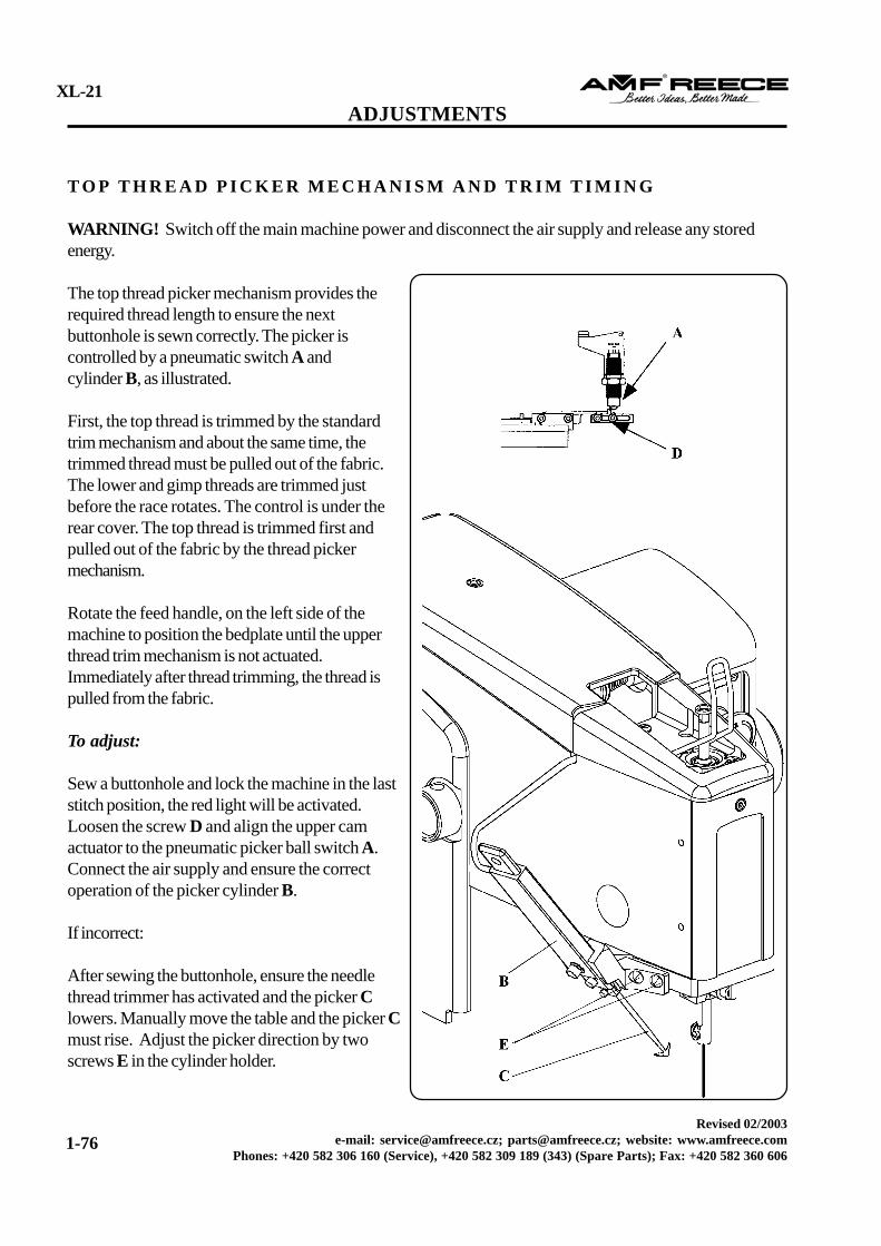
The top thread picker mechanism provides therequired thread length to ensure the nextbuttonhole is sewn correctly. The picker iscontrolled by a pneumatic switch A andcylinder B, as illustrated.
First, the top thread is trimmed by the standardtrim mechanism and about the same time, thetrimmed thread must be pulled out of the fabric.The lower and gimp threads are trimmed justbefore the race rotates. The control is under therear cover. The top thread is trimmed first andpulled out of the fabric by the thread pickermechanism.
Rotate the feed handle, on the left side of themachine to position the bedplate until the upperthread trim mechanism is not actuated.Immediately after thread trimming, the thread ispulled from the fabric.
To adjust:
Sew a buttonhole and lock the machine in the laststitch position, the red light will be activated.Loosen the screw D and align the upper camactuator to the pneumatic picker ball switch A.Connect the air supply and ensure the correctoperation of the picker cylinder B.
If incorrect:
After sewing the buttonhole, ensure the needlethread trimmer has activated and the picker Clowers. Manually move the table and the picker Cmust rise. Adjust the picker direction by twoscrews E in the cylinder holder.
WARNING! Before making the adjustments, disconnect the air supply and release any stored energy andensure the main machine power is off.
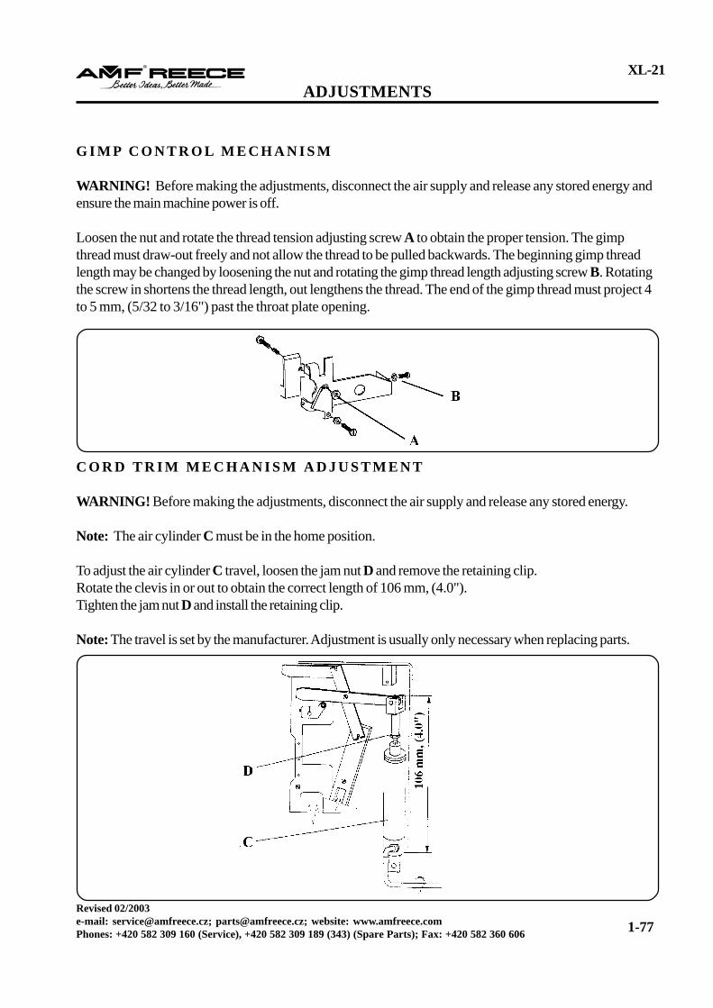
Loosen the nut and rotate the thread tension adjusting screw A to obtain the proper tension. The gimpthread must draw-out freely and not allow the thread to be pulled backwards. The beginning gimp threadlength may be changed by loosening the nut and rotating the gimp thread length adjusting screw B. Rotatingthe screw in shortens the thread length, out lengthens the thread. The end of the gimp thread must project 4to 5 mm, (5/32 to 3/16") past the throat plate opening.
C O R D T R I M M E C H A N I S M A D J U S T M E N T
WARNING! Before making the adjustments, disconnect the air supply and release any stored energy.
Note: The air cylinder C must be in the home position.
To adjust the air cylinder C travel, loosen the jam nut D and remove the retaining clip.Rotate the clevis in or out to obtain the correct length of 106 mm, (4.0").Tighten the jam nut D and install the retaining clip.
Note: The travel is set by the manufacturer. Adjustment is usually only necessary when replacing parts.
Note: View shown is from the underside of the bedplate with the machine in the upright position.
To adjust:
Loosen the actuator B screw and pivot the actuator to obtain a clearance of .635 mm, (.025”) between theroller C and the drive lever A, this is a starting point.
Caution! Shears set with a large amount of cross over may damage the machine and/or parts.
C O R D T R I M M E C H A N I S M A D J U S T M E N T
WARNING! Before making the adjustments, disconnect the air supply and release any stored energy.
WARNING! Before making adjustments, disconnect the air supply and release any stored energy.
Each cord trim model includes a set of shears and a knife for cutting the upper looper thread and all threadtails between the sewn buttonhole end and the stitch plate, eliminating the possibility of dropping stitchesfrom the next buttonhole.
To ensure the shears perform correctly, it is imperative the following are properly adjusted:• Shears set• Lower thread tension• Upper thread trim-off and draw-off• Trimmed off upper thread draw-out
Caution! Failure to maintain these adjustments will result in poor trimming and unnecessary machine downtime. Continued operation of the machine out of adjustment will damage key machine parts, including themain cam.
WARNING! Before making adjustments, disconnect the air supply and release any stored energy.The cord trim shears are designed like a pair of scissors. During trimming, their edges must cross over (0.5 - 1 mm).
Caution! Too much cross over will cause the machine to malfunction and damage key parts. It isimperative the correct adjustment be maintained.
WARNING! Before making adjustments, disconnect the air supply and release any stored energy.
To adjust the shears to the clamp plate installation:
Remove the covers on the right foot plate.
Remove the shears set, sliding the pressure springs I and the nut J. Check the condition of the shears,replace if necessary.
Holding the clamp plate, projections pointing up, insert the shear spring E into the circle cutout area of theclamp plate and place the lower shear F. Place the upper shear G on top of the lower shear.
Insert the shoulder screw H in the circle cutout area of the clamp plate, through the upper and lower shears,spacer, and spring. Add a few drops of oil to the shears.
Rotate the upper and lower shears to ensure the center shoulder screw H has gone through all the partswithout binding.
Tighten the center shoulder screw H and attach the springs I to the outside edges of the upper and lowershears.
Turn the clamp plate upside down and install the shears nut J onto the center shoulder screw H. Using yourfingers, rotate the nut J as far as possible, without tightening.
Position the clamp plate top up and facing forward, use your thumb to move the actuator K to the left,closing the shears.
If the shears are locked into position, adjust the center shoulder screw H just enough to allow the shears toopen, rotate the screw H counterclockwise 1/4 of a turn.
Hold the center shoulder screw H, not allowing it to rotate, turn the plate over and tighten the shears nut J.Ensure the shears cross over each other and return to the open position. If incorrect: repeat steps.
Install the cover plate. Ensure the shears cross over each other and return to the open position. If incorrect,repeat previous steps.
To adjust the clearance:
Loosen the knife holder screws C and adjust the knife holder D, as needed, ensuring the shears movementis not restricted by the clamp mat B. Tighten the knife holder screws C. This adjustment is required onlyafter a knife support D change. Install the spacer only for enlargement of the clearance between uppershears and throat plate.
Caution! The shears must move easily. To prevent damage, do not increase the amount of shear cross overif the shears are not cutting correctly. Do not use the center shoulder screw to increase the shear knifepressure. Check the knife edges and clearances by manually cutting at least 3 threads, replace if needed.
WARNING! Before making adjustments, disconnect the air supply and release any stored energy.
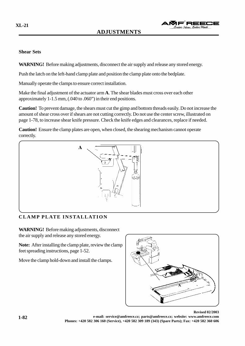
Push the latch on the left-hand clamp plate and position the clamp plate onto the bedplate.
Manually operate the clamps to ensure correct installation.
Make the final adjustment of the actuator arm A. The shear blades must cross over each otherapproximately 1-1.5 mm, (.040 to .060”) in their end positions.
Caution! To prevent damage, the shears must cut the gimp and bottom threads easily. Do not increase theamount of shear cross over if shears are not cutting correctly. Do not use the center screw, illustrated onpage 1-78, to increase shear knife pressure. Check the knife edges and clearances, replace if needed.
Caution! Ensure the clamp plates are open, when closed, the shearing mechanism cannot operatecorrectly.
C L A M P P L AT E I N S TA L L AT I O N
WARNING! Before making adjustments, disconnectthe air supply and release any stored energy.
Note: After installing the clamp plate, review the clampfeet spreading instructions, page 1-52.
WARNING! Before making adjustments, disconnect the air supply and release any stored energy.Using heavy material may cause excessive and incorrectly cut tails.
To correct:Increase the trim delay.
To adjust:Press the push-button to switch off the main machine electrical power.
Press and hold the and push-buttons.
Press the push-button to supply power to the machine.
The LCD display indicates WAIT ! then *************
Release the two push-buttons and press the push-button before the stars disappear.
The LCD display indicates FULL CYCLE 2 step .
Press the sequence push-button to access the hidden parameters.
The LCD display indicates **** MISCEL .
Press the push-button to access the TRIM DEL ( ) LCD display.
To change the number, scroll up or down with the push-buttons.
To set a new number, press the push-button.
The LCD display indicates ******** WAIT when the display indicates FULL CYCLE 2 step
the machine is ready to run. If change is needed, press the push-button to return to the last changed
parameter, in this instance, TRIM DEL ( ) LCD display.
To return to the full menu, press the push-button to switch off the main machine power, then press the
push-button to switch the main machine power on and prepare the machine for operation.
L AT E R A L C A M B L O C K S C U T B E F O R E A N D C U T A F T E R
WARNING! Before making adjustments, disconnect the air supply and release any stored energy.
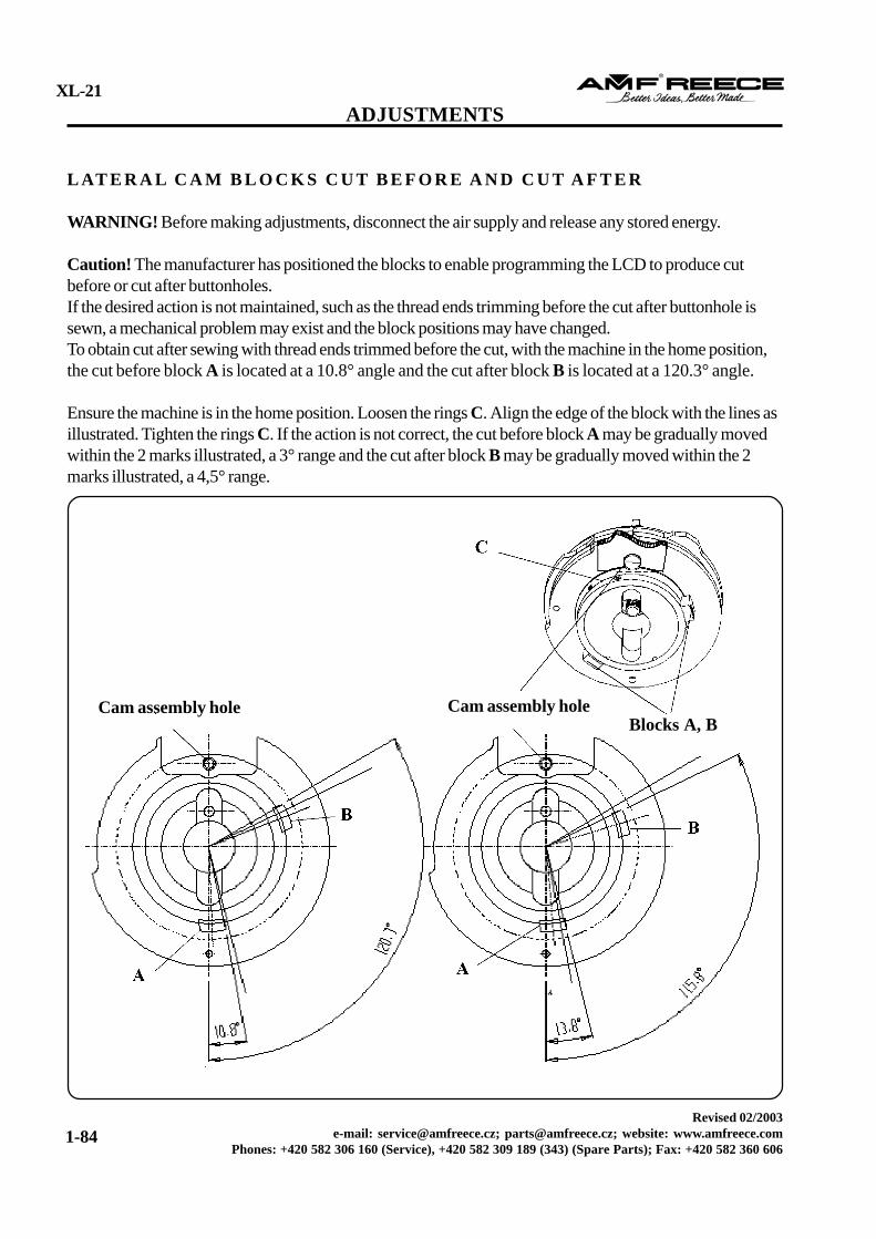
Caution! The manufacturer has positioned the blocks to enable programming the LCD to produce cutbefore or cut after buttonholes.If the desired action is not maintained, such as the thread ends trimming before the cut after buttonhole issewn, a mechanical problem may exist and the block positions may have changed.To obtain cut after sewing with thread ends trimmed before the cut, with the machine in the home position,the cut before block A is located at a 10.8° angle and the cut after block B is located at a 120.3° angle.
Ensure the machine is in the home position. Loosen the rings C. Align the edge of the block with the lines asillustrated. Tighten the rings C. If the action is not correct, the cut before block A may be gradually movedwithin the 2 marks illustrated, a 3° range and the cut after block B may be gradually moved within the 2marks illustrated, a 4,5° range.
A D J U S T M E N T O F T H E H E I G H T O F T H E U P P E R T H R E A D T R I MK N I F E
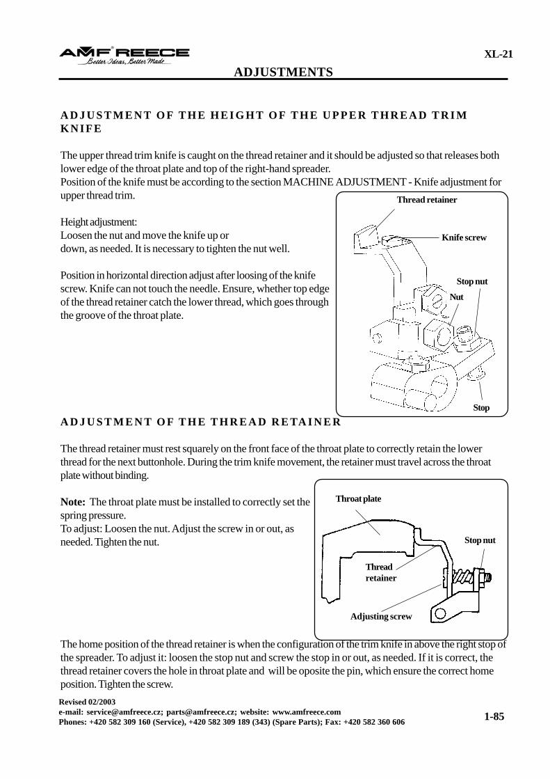
The upper thread trim knife is caught on the thread retainer and it should be adjusted so that releases bothlower edge of the throat plate and top of the right-hand spreader.Position of the knife must be according to the section MACHINE ADJUSTMENT - Knife adjustment forupper thread trim.
Height adjustment:Loosen the nut and move the knife up ordown, as needed. It is necessary to tighten the nut well.
Position in horizontal direction adjust after loosing of the knifescrew. Knife can not touch the needle. Ensure, whether top edgeof the thread retainer catch the lower thread, which goes throughthe groove of the throat plate.
A D J U S T M E N T O F T H E T H R E A D R E TA I N E R
The thread retainer must rest squarely on the front face of the throat plate to correctly retain the lowerthread for the next buttonhole. During the trim knife movement, the retainer must travel across the throatplate without binding.
Note: The throat plate must be installed to correctly set thespring pressure.To adjust: Loosen the nut. Adjust the screw in or out, asneeded. Tighten the nut.
The home position of the thread retainer is when the configuration of the trim knife in above the right stop ofthe spreader. To adjust it: loosen the stop nut and screw the stop in or out, as needed. If it is correct, thethread retainer covers the hole in throat plate and will be oposite the pin, which ensure the correct homeposition. Tighten the screw.
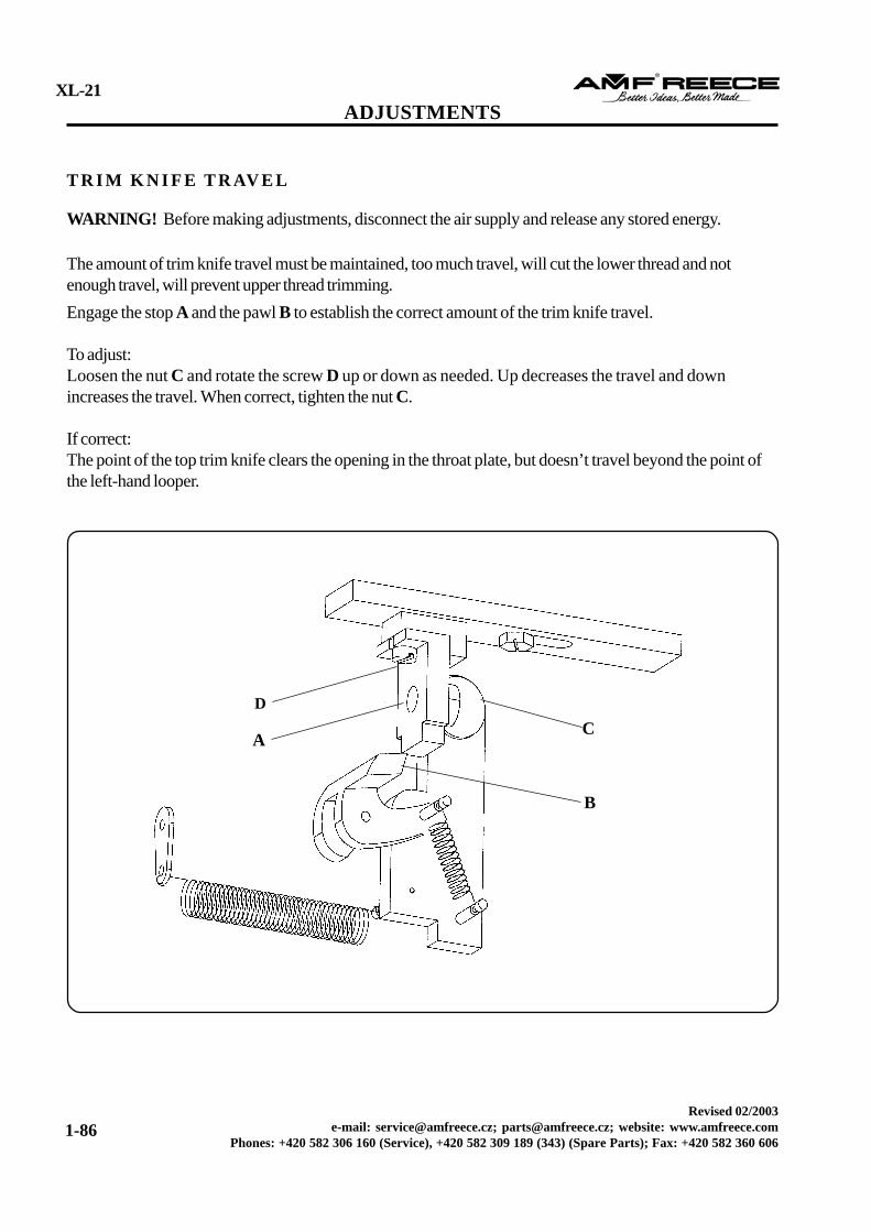
WARNING! Before making adjustments, disconnect the air supply and release any stored energy.
The amount of trim knife travel must be maintained, too much travel, will cut the lower thread and notenough travel, will prevent upper thread trimming.Engage the stop A and the pawl B to establish the correct amount of the trim knife travel.
To adjust:Loosen the nut C and rotate the screw D up or down as needed. Up decreases the travel and downincreases the travel. When correct, tighten the nut C.
If correct:The point of the top trim knife clears the opening in the throat plate, but doesn’t travel beyond the point ofthe left-hand looper.
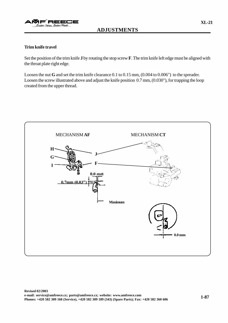
Set the position of the trim knife J by rotating the stop screw F. The trim knife left edge must be aligned withthe throat plate right edge.
Loosen the nut G and set the trim knife clearance 0.1 to 0.15 mm, (0.004 to 0.006") to the spreader.Loosen the screw illustrated above and adjust the knife position 0.7 mm, (0.030"), for trapping the loopcreated from the upper thread.
Caution! If the small play is not observed, a risk of trapping and trimming the bottom thread exists.
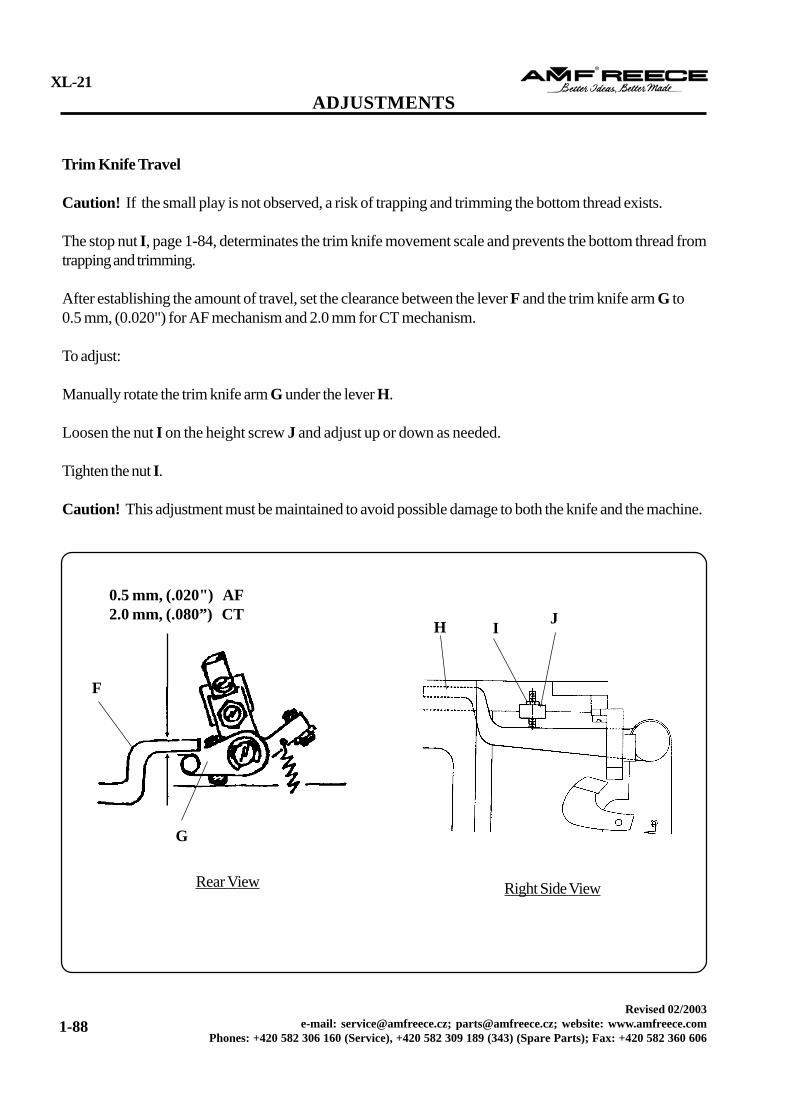
The stop nut I, page 1-84, determinates the trim knife movement scale and prevents the bottom thread fromtrapping and trimming.
After establishing the amount of travel, set the clearance between the lever F and the trim knife arm G to0.5 mm, (0.020") for AF mechanism and 2.0 mm for CT mechanism.
To adjust:
Manually rotate the trim knife arm G under the lever H.
Loosen the nut I on the height screw J and adjust up or down as needed.
Tighten the nut I.
Caution! This adjustment must be maintained to avoid possible damage to both the knife and the machine.
WARNING! Before making adjustments, disconnect the air supply and release any stored energy.
Note: This adjustment corresponds to the buttonhole length and must be performed immediately before thetop thread picker activates.
To adjust:With the machine in the home position, loosen the screw A and adjust the clearance between the stop B andthe pawl C from 18 to 19 mm, (45/64 to 3/4", 0.700 to 0.750").Move the holder D to the front or rear as needed.When the distance is correct, tighten the screw A.
Caution! This adjustment must be maintained, the tip of the knife must clear the throat plate hole and notmove behind the tip of the left looper. Failure to maintain the proper clearance may result in damage to theknife and/or machine.
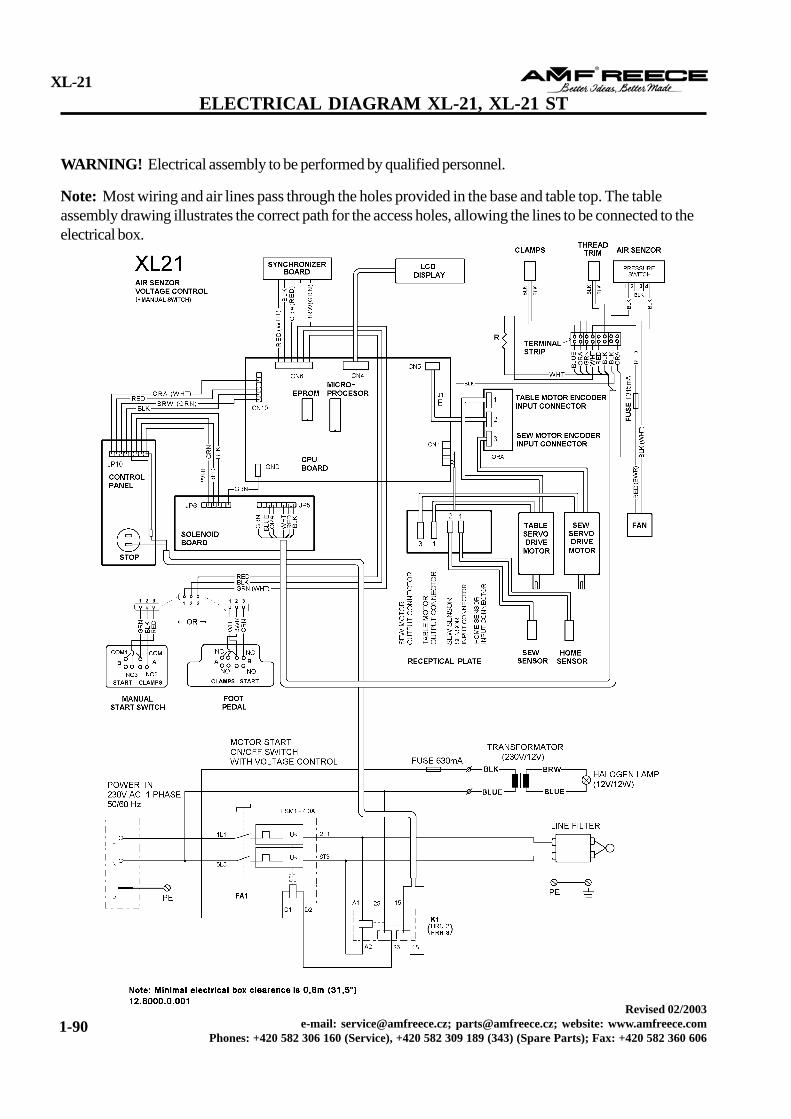
WARNING! Electrical assembly to be performed by qualified personnel.
Note: Most wiring and air lines pass through the holes provided in the base and table top. The tableassembly drawing illustrates the correct path for the access holes, allowing the lines to be connected to theelectrical box.
WARNING! Before performing any maintenance, switch off the main machine power to preventaccidental starting of the machine. Disconnect the air supply and release any stored energy.
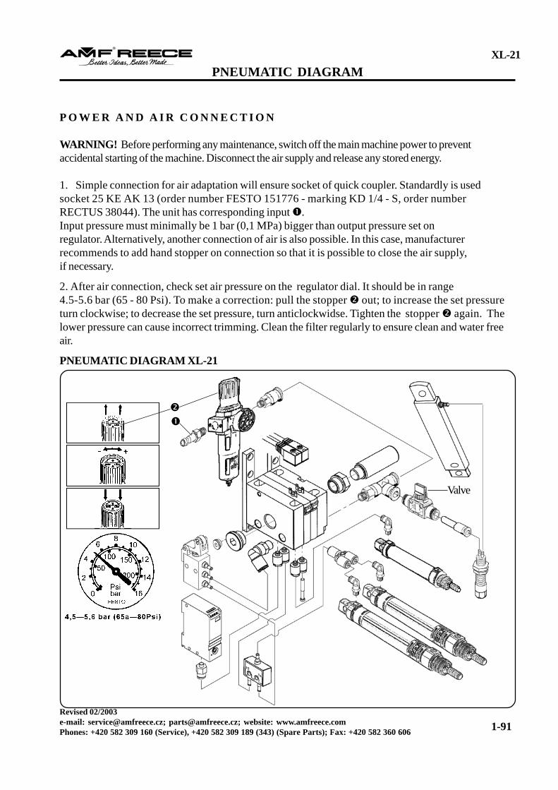
1. Simple connection for air adaptation will ensure socket of quick coupler. Standardly is usedsocket 25 KE AK 13 (order number FESTO 151776 - marking KD 1/4 - S, order numberRECTUS 38044). The unit has corresponding input .Input pressure must minimally be 1 bar (0,1 MPa) bigger than output pressure set onregulator. Alternatively, another connection of air is also possible. In this case, manufacturerrecommends to add hand stopper on connection so that it is possible to close the air supply,if necessary.
2. After air connection, check set air pressure on the regulator dial. It should be in range4.5-5.6 bar (65 - 80 Psi). To make a correction: pull the stopper out; to increase the set pressureturn clockwise; to decrease the set pressure, turn anticlockwidse. Tighten the stopper again. Thelower pressure can cause incorrect trimming. Clean the filter regularly to ensure clean and water freeair.
WARNING! Before performing any maintenance, switch off the main machine power to preventaccidental starting of the machine. Disconnect the air supply and release any stored energy.
To obtain the maximum quality product with the least amount of machine down time and cost, a goodpreventive maintenance program must be regularly enforced.
Routine cleaning and upkeep requires: oilvacuum cleanerpaint brushparts brush
WARNING! Never use an air pressure hose instead of a vacuum. Dirt particles may contaminate the camcausing possible machine damage or personal injury.
Periodic Maintenance Checklist:
Daily:Remove lint from the loopers and spreaders.Clean the oil pan.
Weekly:Visual inspection of internal and external mechanisms.Inspect and replace the knife and block, if needed.Oil the machine according to the lubrication diagram, page 1-9.Ensure correct belt tension.
Monthly:Check for loose fasteners and tighten, if necessary.Inspect for worn and damaged parts and replace, if needed.Check throat plate wear and replace, if needed.
6 Months:Perform complete machine parts inspection.Ensure the correct stitch drive clearance.Ensure all machine adjustments are accurate.Perform complete wiring inspection.Change lubricant in the ball bearings.Clean the dirt and water from the air pressure regulator filter.
R E C O M M E N D AT I O N F O R M A C H I N E M A I N T E N A N C E
Gearings dismantlingThe machine is operated for 8 hours in a company to modify all machine gears for optimal machine liveness.During the assembly, the manufacturer recommands to make the colour marks on the appropriate teeth andteeth blank of the gearings and assemble the parts according to these marks.
The bearing (see page 3-26, det. 32) of the rear drive shaft is dismantled with its bushing:- after head and bedplate dismantling- after drive shaft removing- after loosing the screw M8 from the base bottom- change the bearing outside the machine and then assmeble the bushing with new bearing to the machine
Machine noisinessRolls (17.0041.8.003, 17.0041.8.096) in the stitch cam (page 3-52) and the round key (see page 3-18)should not have any clearance to protect against machine noisiness. Therefore, change the rolls during everydismantling and check a clearance of the drive lever stud.
C L A M P F E E T F O R S E W I N G H E AV Y O R T H I N FA B R I C
The accessories CT is mentioned in manual on page 3-64.
This accessory contains clamp feet for sewing on heavy fabrics, especially denim (18.0066.7.408-9 widthof teeth 1.4 mm) and clamp feet for sewing on thin fabrics (18.066.7.412-13 width of teeth 5.8 mm).
Narrow clamp feet for sewing on the heavy, folded fabrics, is possible to adjust according to the sewingneeds (according to the picture by the whole surface against the short clamp mat or only part of the edgeagainst the short clamp mat according to the fabric elasticity.)
Clamp feet for sewing on the thin fabric clamp sewn fabrics by the whole surface, which isadvantageous for thin fabric sewing.
Caution!When you individually adjust the clamp feet, the clamp plate can not touch the needle during sewing. Afterclamp feet mounting, it is necessary by slow hand turning of the hand wheel try if there is a clearancebetween the needle and the right and left clamp feet.
It is not a part of supply, but it is possible to order it (see page 3-69, Parts). It is not possible to adjust theupper thread end on this upper thread draw-off. This one is suitable for thicker materials (for exampledenim) and is not suitable for light materials.
Threading the Machine
WARNING! Switch off the main machine power, disconnect the air supply and release any stored energy.
Note: When threading the XL-21 in the home position, the race will be toward the rear of the machine.
Raise the upper cover and rotate 90°. Thread the machine, as illustrated. Threading wires , ensureeasy threading. Change the tension by nut . Adjust the disc after loosing the nut and rotate the discclockwise to decrease the tension or anti-clockwise to increase. Tighten the nut.Note: Using thin fabric requires increased upper thread tension.
The XL-21 ST machine is only supplied in the modification CT, which mean all threads trimming,cutting after sewing and with the auxiliary pneumatic clamping of the sewn work, which disallow earlyextraction of the sewn work. It avoids incorrect trimming of the thread ends and possible fabrictrimming.
It is used for buttonhole sewing in a small pockets, especially on denim. The buttonholes sewing in asmall pockets is allowed by:- the short travel of the table, which is 12 mm shorter in this mechanism than in standard machine- the possibility to hold the outer material of the pocket to avoid its incorrect sewing.
The XL-21 ST allows the buttonholes sewing from 16 to 22 mm. The buttonhole sewing without cordtrim and with short ends is also possible on this machine type, but after changing the clamp plates(however, the maximal buttonhole length is 12 to 22 mm).
T H E D I F F E R E N T S E T T I N G O F S O M E M E C H A N I S M S
The guide plate
On the machine XL-21 ST, the guide plate is 12mm closer to operator. There are two pairs ofthreads on the bedplate. That is why it is possible torearrange it to standard mechanism. The guide plateis fixed by pins to the bedplate.
Clamp Feet Spreading
The clamp feet spreading on the XL-21 ST machine is similar to XL-21 standard machine. Thespreading rollers are installed in the outside thread, see picture.
T H E A U X I L I A R Y FA B R I C C L A M P I N G A D J U S T M E N T
Adjustment of the auxiliary clamping stroke in connection of clamp feet:
Insert a piece of material under the clamp feet and press the black push-button CLAMPS DOWN.By pressing the white push-button HOME POSITION, the table moves to the operator serviceposition (see page 1-12 Operator push-button switches). Loosen the locking nut on the arms ,
and adjust the auxiliary arms , by screw . The auxiliary arms must properly hold the materialwithout pneumatic cylinders . Press the HOME POSITION push-button to bring the machine to thehome position.
Adjustment of the working cylinder distance for the auxiliary clamping stroke:
Adjust the distance of the pneumatic cylinder fromthe stop of the auxiliary clamping , . Adjust thepneumatic cylinder to the distance 3 mm in the homeposition (see picture). To adjust the cylinder distance,loosen the nut on the cylinder and then loosen thescrews under this cylinder and move the cylinderholder.
Adjustment of the auxiliary pneumatic holding of the sewing work:
The arms are controlled by valve delay duringthe trimming action. To adjust:
1. Open the both screws of the speed control-ler ASD 230F 04 - M5 (loosen counterclockwise)after loosing the locking nut .
2. To obtain the correct thrust, adjust the screw ofthe speed controller (tighten clockwise). It is possibleto adjust the thrust in range 0 ATM to maximal sup-plied pressure to the input device.
3. Then, adjust the screw (tighten clockwise).Where a delayed lifting of the auxiliary arms starts todisplay, adjust needed delay. It is possible to adjustthe delay in range 0-2 s.
4. After speed controller adjustment, tighten the screws by nut .
T H E M A C H I N E VO LTA G E P R O T E C T I O N
The power voltage control (Voltage monitoring relay HRN-3) is installed in the machine controlsystem. This power voltage control cautions a machine operator if the supply voltage is not in the requiredrange (165 V to 255 V) and the machine could be damaged.
The voltage monitoring relay HRN-3 is placed next to the main power switch . It is adjusted andsealed from the manufacturer. If the supply voltage is in the required range, the green LED Un indicates iton the voltage monitoring relay. If the upper limit (255 V) of the supply voltage is exceeded, the red LED
indicates it. If the supply voltage is lower than 165 V, the green LED stops indicating and the red LED indicates it.
If the supply voltage returns to the required range, the red LED stops indicating.
The upper limit (255 V) is exceeded
If the supply voltage is higher than the upper limit, the black STARTbutton will not stay engaged.1. a) When the START button is pressed and will not stay engaged,
the LEDs Un and blink. (The upper limit is exceeded) b) When the START button is pressed and will not stay engaged,
only Un LED blinks. (See Troubleshooting, page 2-2).
If the supply voltage is higher than the upper limit during a sewing, the machine is automatically switched offto prevent control electronics damage. When the voltage level is restored to acceptable levels(165 - 255 V), it is possible to start the machine by the standard way (See - 1-17).
If the supply voltage is below the lower limit 165 V, the machineautomatically enters EMERGENCY STOP and the red and greenLEDs will begin flashing on the operator control panel ). The onlyred LED indicates on the voltage monitoring relay .If the supply voltage is decreased during a sewing, the machineautomatically stops.
When the voltage level is restored to acceptable levels(165 - 255 V), it is possible to start the machine by the standardway (See - 1-17).
Motors started and operated fora short time, then stopped.
The machine fails to cycle.
Uneven feeding.
Machine rotating hard at the eye.
Machine fails to stop stitching.
Machine does not reach homeposition.
Machine fails to stop.
No power to the electrical panel.
The message, Air sensor yes, isdisplayed.Defective starter switch.The upper limit (255V) of thesupply voltage is exceededThe supply voltage is lower than165V
Incorrect voltage.
Excessive cutting pressure.
Incorrect belt tension.
Dirt in the sector teeth.
Belt has fallen off.
Main cam friction is too tight ortoo loose.Improperly set main shaft brake.
Worn feed clutch.
Dirt lodged between the upperand lower sector teeth.
Relays not functioning correctly.
Worn or incorrectly adjusteddrive belt.Excessive cutting pressure.
Home sensor not activating.
Check the electrical plug andwiring.Change the Air sensor parameterto no.Replace the starter switch.See page 1-102
See page 1-103
Check the electrical plug andwiring connections.Decrease the cutting pressure,page 1-75Correct the belt tension, page1-7.Clean the sector teeth and test byfreely rotating the completeassembly forward and backward.
Install the belt.
Adjust for proper friction, page1-57.Adjust for proper compression,page 1-58.Replace the feed clutch.
Remove the dirt.
Repair or replace the relays.
Replace and adjust the drive belt.
Decrease the cutting knife and theblock pressure, page 1-75.
Set clearance between the sensorand the sensor block, page 1-49.
Machine does not grip the fabric,or releases to soon.
Machine does not release thefabric.
Machine fails to cut the fabric.
Cutting lever sticks and fails toreturn.
Uneven cutting.
Cutting stitches, on a Cut Aftermachine.
Clamp feet incorrectly adjusted.Incorrect or insufficient airpressure.
Machine is not reaching the homeposition.Incorrect clamp disengagement.
Damaged knife.Damaged cutting block.
Insufficient cutting pressure.
Damaged cutting lever.Damaged cutting cam.Damaged cutting lever camfollower.
Faulty extension spring.Pins sticking.Excessive cutting lever pressure.
Uneven clamp spread.
Cutter is not centered.Incorrectly installed cutting steels.Cutting steel is not fitted to theknife.
Loose upper thread tension.
Insufficient clamp spread.
Clamps not holding the fabriccorrectly.Cutting knife is not centered.
Adjust the clamp feet, page 1-54.Ensure the air pressure indicatesthe minimum 4.5 bar, (65 PSI),increase pressure if needed.
Check the sensors, page 1-47.
Check the air supply line.
Replace the knife.Repair or replace the cuttingblock, page 1-73.Increase the cutting knife andblock pressure, page 1-73.Replace the cutting lever.Replace the cutting cam.Replace the cam follower.
Replace the spring, page 1-73.Adjust and/or lubricate the pins.Decrease the cutting leverpressure.
Adjust the clamp spread, page 1-52.Center the cutter, page 1-73.Correctly install the cutting steels.Perform the replacement of thecutting steel adjustment, page1-73.
Increase the upper thread tension,page 1-36.Increase the clamp spread, page1-52.Adjust the clamp grippingpressure, page 1-54.Center the cutting knife, page 1-73.
Center the cutting steel to theknife, page 1-73.Adjust the bite and cutting space,page 1-60.Ensure the correct looper andspreader timing.Adjust for the proper lengthbuttonhole, page 1-61.
Correctly install the needle.Replace the needle.Ensure the needle does notcontact any object.Decrease the looper to the needleclearance, page 1-67.Correct the looper timing, page1-67 to 1-70.Replace worn parts.Ensure correct looper carrieradjustment.Replace loopers.Correctly adjust the spreadertiming.Decrease the clamp foot toneedle entry point clearance, page1-53.Correctly adjust the clampspread, page 1-52.Correctly thread the machine,page 1-31 to 1-37.Correctly adjust the tensionsettings, pages 1-32 to 1-36
Adjust for the proper cuttingspace, page 1-60.Slightly increase the bite size andset the loopers and spreaders.
Cutting steel is not centered to theknife.Stitches are being cut on bothsides.
Incorrect buttonhole length.
Incorrect needle installation.Bent or burred needle point.Needle deflection.
Excessive looper to needleclearance.Incorrect looper and needletiming.Excessive looper carrier end play.
Bent or worn loopers.Incorrect spreader timing.
Excessive clamp foot to needleentry point clearance.
Sew start thread lenght is tooshort.Fork spreader is not positionedover the eye looper hole.Incorrect right hand looper timing.
Excessive clamp foot to needleentry point clearance.
Damaged loopers and/orspreaders.
Excessive upper thread tension.
Incorrect needle to looperclearance.Incorrect looper to spreadertiming.Sharp edges along the threadpath.Incorrect needle insertion, or bentneedle.Incorrect threading.
Excessive lower thread tension.
Incorrect left-hand spreadersetting.Refer to the breakage of theupper thread possible causes.
Adjust the upper tension startrelease, page 1-36.Position the fork spreader overthe eye looper hole.Properly adjust the looper timing,page 1-49 to 1-71.Decrease the clamp foot toneedle entry point clearance, page1-53.Replace the loopers and/orspreaders.
Decrease the upper threadtension, page 1-36.Adjust the needle to looperclearance, page 1-67.Correct the looper to spreadertiming, pages 1-66 to 1-71.Eliminate the sharp edges alongthe thread path.Replace or correctly insert theneedle.Correct the machine threading,page 1-31 to 1-37.
Decrease the lower threadtension, page 1-32.Correct the left-hand spreadersetting, page 1-71.Refer to the breakage of theupper thread possible solutions.
Thread breaking and runningback out of the needle bar.
Incorrect eye shape.
Inconsistent stitching on thestraight portion of the buttonhole.
Thread is incorrectly positionedin the troatplate:Lints in the troatplateBroken springIncorrectly loosened lowerthread.Thread ends drawn into thetroatpate.Refer to the breakage of theupper thread possible causes.
Incorrect trimming.
Incorrect tension.Incorrect threading.
Incorrect lateral cam timing.Incorrect cutting lever adjustment.
Row of stitching is cut by theknife after the sewing cycle iscomplete.
Uneven stitch density.
Noisy brakes
Decreased buttonhole quality.
Stitches are pulling up.
Incorrect cutting width.
Incorrect cutting lever setting.
Incorrect clamp spread.
Buttonhole length too short.
Main shaft brake shoe or brakeband is loose.
Main shaft brake shoe or brakeband is overtightened.
The functional and aestheticquality of a buttonhole isinfluenced by:Stitch density.Number of buttonhole eyestitches.Incorrect amount of fabricspread.Incorrect distance between thestitch line and the buttonhole axis.Incorrect loopers and spreaderstiming.
The type of thread and fabric willaffect the buttonhole appearance.Incorrect upper and lower threadtensions.
Incorrect loopers and spreaderstiming.
Correct the cutting widthpage1-60.Correct the cutting lever setting,page 1-73.Correct the clamp spread setting,page 1-52.Correctly adjust the length gauge,page 1-63.
Tighten main shaft brake shoe ,page 1-56.If even stits density is notobtained, you may need to tightenthe brake band, page 1-56.
Reduce high thrust, page 1-56,otherwise machine could bedamaged.
Adjustments, pages 1-45 to 1-87.
Correct the stitch density.Correct the number of buttonholeeye stitches.Correct the amount of fabricspread.Correct the distance between thestitch line and the buttonhole axis.Correct the loopers andspreaders timing.
Adjust settings to accommodatethread and fabric.Correct the upper and lowerthread tensions,pages 1-32 to 1-36.Correct the looper and spreadertiming, page 1-66 to 1-71.
Machine power is switched on,but the LCD screen is blank.
Machine power is switched on,but the LCD screen only displaysblank boxes.
Machine power is switched on,the display indicates “full cycle”,the start treadle is pressed to thefirst stage, (clamps down), but theclamps do not lower.
Lights and switches on theoperator control panel are notoperating. The machine will notcycle and the display indicates“Not Needle Up”.
The LCD is not properlyconnected to the control box.The power supply is not properlyconnected to the control box.The LCD unit has failed.
The LCD is not properlyconnected to the control box.The LCD unit has failed.
Malfunctioning treadle switch.
Incorrect DC solenoid valveconnection.
Incorrect wiring.
Needle is not in the up position.
No power on the synchronizerboard.
Ensure the correct connectionaccording to the diagram.Ensure the correct connectionaccording to the diagram..Ensure the synchronizer boardred LED is activated, if notactivated, the LCD has failed.Replace the LCD.
Switch off the main power andunplug the LCD from the controlbox. Insert the LCD connectionagain, switch on the main powerand check the display for correctoperation.If problem still exists, replace thefailed LCD.
Using the “System Test” ensurethe start treadle is operatingcorrectly.Check the clamp solenoid valveconnection inside the control boxand ensure tle valve connectorlight is activated and if thisconnector is connected to thevalve, the valve must beactivated.
Using the operator panel wiringdiagram, correct the wiring.Manually rotate the handwheeluntil the machine is in the needleup position, and the red indicatorlight is activated.Ensure the synchronizer boardhas power and the red LED isactivated.
Lights and switches on theoperator control panel are notoperating. The machine will notcycle and the display indicates“Not Needle Up”.
Lights/switches are activated.
The machine will not cycle andthe display indicates “not home”.
The machine will not cycle andthe display indicates “watch dogerror”.
Align the synchronizer diskmagnetwith the board sensor. If the greenLED is activated, a signal isreceived. If the green LED is notactivated, adjust the synchronizerto obtain a 3 mm, (.118") clearancebetween the disk and the sensor.
Reverse the magnet, if no signalreceived, replace the synchronizerboard.
Press the home push button on the LCD, or press the whitecontrol panel push-button..
Ensure the home sensor height is0.5 to 1 mm (.020 to .040"),above the home position sensorblock.Using the “System Test”, check thehome sensor operation.Check the connection from theterminal board to the control box.
Ensure proper cable connections.Remove the drive belt and performthe table test in the “Systems Test”.
The synchronizer disk is too farfrom the sensor to interpret thesignal.
Synchronizer disk magnet isinstalled backwards.
The machine is not in the homeposition.
Incorrect home sensor clearance.
The home sensor signal is notbeing received.
The motor cables are notproperly connected to the controlbox.
Pressing the start treadle movesthe machine bedplate, but themachine does not sew and thebedplate continuously cycles.
The machine moves from thehome position to the sew positionand stops. The display indicates“watch dog error”.
The machine sews a buttonhole,then stops and does not completethe cycle. The display indicates“not needle up”.
The machine sews a buttonhole,then stops and does not completethe cycle. The display indicates“watch dog error”.
The machine sews a buttonhole,and stops while punching thebuttonhole slot. The displayindicates “watch dog error”.
The first stitch sensor is notreceiving a first stitch sensorblock signal.
Incorrect start treadleconnections.
The cables are not properlyconnected to the control box.
Loose sewing motor drive belt.
Incorrect positioning speed andbrake force parameters.
Malfunctioning control box relay.
Loose table motor drive belt.
Switch on the machine power andensure the red first stitch sensorLED is activated, (the metalobject must be close to thesensor).Ensure the sensor and the sensorblock clearance is 0.5 to 1 mm(.020 to .040").Check the connection from theterminal board to the control box.Perform the “Systems Test”.Using the start treadle wiringdiagram, or the Test Menu,correct the connections
Ensure proper connections fromthe sew motor to the control box.Remove the V-belt and performthe “Systems Test”.
Properly tension the drive belt,page 1-7.Correct the parameter settings.
Perform the “Relay Test” toensure correct mechanicaloperation.
Disconnected or incorrect airpressure.Incorrect LCD parameters.Mechanism binding.
Clamping air cylinder notoperating.
Solenoid valve not operating.
Damaged supply line.Restricted air flow.Disconnected or incorrect airpressure.
Incorrect LCD parameters.Solenoid valve not operating.
Damaged supply line.Restricted air flow.Shearing air cylinder notoperating.
Check function of pressure switch
Check all connections and ensureproper 4.5 bar, (65 PSI) ofminimal air pressure.Check parameter settings.Ensure free movement of theclamp arm assembly.
Press the arrow up/down
push button on the LCD, oruse the black button on theoperator control panel to checkfor proper operation.Replace cylinder if needed.Ensure the valve connector light isactivated,the valve must beactivated. Ensure this connector isconnected to the valve.Replace supply line.Correct air flow.Check all connections and ensureproper 4.5 bar, (65 PSI) ofminimal air pressure.Check parameter settings.Ensure the valve connector lightis activated, the valve must beactivated. Ensure this connector isconnected to valve.Replace supply line.Correct air flow.Press the SBT and the arrow
up push button on theLCD to ensure proper cylinderoperation. Replace the cylinder ifneeded
A program is available to test the major input functions, synchronizer, and encoder for correct operation.To access the test program:
Press the and push buttons at the same time.
When the message SYSTEM TEST is displayed, the following may be tested:
Needle positionStart treadleHome and sew sensors
With the machine in the home position, the display reads “1-HOMESENSOR”, indicating theprocessor is receiving a signal from the home sensor.
Note: Any other message indicates a home sensor malfunction.
Note: Only one function may be displayed, if two signals are being received the signal with thehighest priority will be displayed.
The order of priorities:-1- Home sensor-2- Sew sensor-4- Clamp down-5- Start treadle-6- Needle up
Home and Sew Sensor Testing
Manually rotating the machine through a cycle, changes the display and indicates which signal is beingreceived.Example: Starting the machine in the home position, the display indicates “HOMESENSOR”. When thehandwheel is rotated away from the home position, the display indicates “NEEDLE UP”. If the machine isnot in the Needle Up position and no other signals are received, the display will indicate “TEST INPUTS”.Continue rotating the handwheel and the display will indicate “HOMESENSOR” as the machine reaches thepunch position plateau of the home sensor block.Continue rotating the handwheel until the Sew sensor reaches the first stitch plateau of the Sew sensorblock, page 1-44. The display indicates “2-SEW SENSOR”.
Use the handwheel to rotate the machine manually until the display message reads “NEEDLE UP” or“TEST INPUTS”.Lightly toe the start treadle until the message reads “4-CLAMP DOWN”.Fully toe the start treadle. The message should now read “5-START”.
Motors Belt Tension
Caution! To avoid damage to the machine, remove the belts before performing this test.
Testing the Motors
Press the Round arrow push button, the displays indicates “ONLY w/adapter”.
Press the Round arrow push button again, the display indicates “TEST TABLE MOTOR”.
Lightly toe the right-hand start treadle to the first position. The motor will begin to rotate with a fixed lowcurrent (no speed control).
Fully release the start treadle. The message now reads 800 pls (pulses). Any number other than 800indicates a failure in the system and the machine must not be used until the failure is corrected.
Fully toe the start treadle. The message now reads 100 pls (pulses). Any number other than 100 indicates afailure in the system, and the machine must not be used until this failure is corrected.
Sew Motor Test
Press the home push button, the display indicates “TEST SEW MOTOR”.
Test the sew motor by following the same procedure to test the table motor.