EZ-Set Torsion Spring System™ Assembly Installation Instructions EZ-Set Torsion Spring System™ Assembly Installation Instructions These instructions are to be used in conjunction with your standard installation manual. Follow the manual up through “Assembling & Installing the Track” — except leave a minimum of 1 /2" per side between track and door, and just loosely (temporarily) attach 3 /8"-16 x 3 /4" carriage bolt in flag bracket. Please read and understand these instructions completely before proceeding with the instal- lation of the EZ-Set Torsion Spring System™. Carefully follow these instructions to avoid personal injury or property damage. Use these instructions for the EZ-Set Torsion Spring System™ only. (If you have regular torsion springs, extension springs, or the EZ-Set Extension Spring System™ see the standard Installation Manual.) Tools Needed • 3 /8" Medium duty reversible power drill • 3 /8" Open end wrench • 3 /16" Hex wrench • 1 /8" Drill bit • 1 /4" Insert bit (included) In the interest of safety this symbol means WARNING or CAUTION. Personal injury and/or property damage may occur unless instructions are followed carefully. ALL REFERENCES TO LEFT HAND AND RIGHT HAND ARE MADE ASSUMING THAT YOU ARE INSIDE THE GARAGE LOOKING OUT.
Transcript
EZ-Set Torsion Spring System™Assembly Installation Instructions
These instructions are to be used in conjunctionwith your standard installation manual. Followthe manual up through “Assembling & Installingthe Track” — except leave a minimum of 1/2" perside between track and door, and just loosely(temporarily) attach 3/8"-16 x 3/4" carriage boltin flag bracket.
Please read and understand these instructionscompletely before proceeding with the instal-lation of the EZ-Set Torsion Spring System™.Carefully follow these instructions to avoidpersonal injury or property damage.
Use these instructions for the EZ-Set TorsionSpring System™ only. (If you have regulartorsion springs, extension springs, or the EZ-SetExtension Spring System™ see the standardInstallation Manual.)
Tools Needed
• 3/8" Medium duty reversible power drill• 3/8" Open end wrench• 3/16" Hex wrench• 1/8" Drill bit• 1/4" Insert bit (included)
In the interest of safety this symbol meansWARNING or CAUTION. Personal injuryand/or property damage may occur unlessinstructions are followed carefully.
ALL REFERENCES TO LEFT HAND AND RIGHT HAND ARE MADE ASSUMINGTHAT YOU ARE INSIDE THE GARAGE LOOKING OUT.
2
Parts List
TORSIONTUBE(Full Length)(If so equipped)
DESCRIPTION DOOR TYPE QTY.
WINDINGUNIT
BRACKET
DRUMS
TORSIONTUBE(Half Length)(If so equipped)
TUBECOUPLER(If so equipped)
ENDBEARINGSUPPORT
Sngl. Car, Sngl. Spring
Dbl. Car, Sngl. Spring
Dbl. Car, Dbl. Spring
Sngl. Car, Sngl. Spring
Dbl. Car, Sngl. Spring
Dbl. Car, Dbl. Spring
Sngl. Car, Sngl. Spring
Dbl. Car, Sngl. Spring
Dbl. Car, Dbl. Spring
Sngl. Car, Sngl. Spring
Dbl. Car, Sngl. Spring
Dbl. Car, Dbl. Spring
Sngl. Car, Sngl. Spring
Dbl. Car, Sngl. Spring
Dbl. Car, Dbl. Spring
Sngl. Car, Sngl. Spring
Dbl. Car, Sngl. Spring
Dbl. Car, Dbl. Spring
Sngl. Car, Sngl. Spring
Dbl. Car, Sngl. Spring
Dbl. Car, Dbl. Spring
11222222211122211111——11
DESCRIPTION DOOR TYPE QTY.
LEFT SIDETORSIONSPRING
RIGHT SIDETORSIONSPRING
LAG SCREW1⁄4" X 1"
SHEETMETALSCREW#14 X 5⁄8"
CARRIAGEBOLT3/8" - 16 X 3/4"
FLANGENUT3/8" X 16
Sngl. Car, Sngl. Spring
Dbl. Car, Sngl. Spring
Dbl. Car, Dbl. Spring
Sngl. Car, Sngl. Spring
Dbl. Car, Sngl. Spring
Dbl. Car, Dbl. Spring
Sngl. Car, Sngl. Spring
Dbl. Car, Sngl. Spring
Dbl. Car, Dbl. Spring
Sngl. Car, Sngl. Spring
Dbl. Car, Sngl. Spring
Dbl. Car, Dbl. Spring
Sngl. Car, Sngl. Spring
Dbl. Car, Sngl. Spring
Dbl. Car, Dbl. Spring
Sngl. Car, Sngl. Spring
Dbl. Car, Sngl. Spring
Dbl. Car, Dbl. Spring
Sngl. Car, Sngl. Spring
Dbl. Car, Sngl. Spring
Dbl. Car, Dbl. Spring
111——1222444222444444222
NOTE: Doors greater than 10 feet in width aredouble car doors.
LAG SCREW5⁄16" X 15⁄8"
CENTER SUPPORT
Sngl. Car, Sngl. Spring
Dbl. Car, Sngl. Spring
Dbl. Car, Dbl. Spring
S C A L E
1⁄4 1⁄2 3⁄4 1" 2" 3"
Sngl. Car, Sngl. Spring
Dbl. Car, Sngl. Spring
Dbl. Car, Dbl. Spring
TUBERETAINER
NOTE: If you are missing any parts fromthe parts list, do not return it to the store.Please call the consumer support numberlisted on the front page of your standardinstallation manual.
3
Installing The EZ-SetTorsion Spring System™
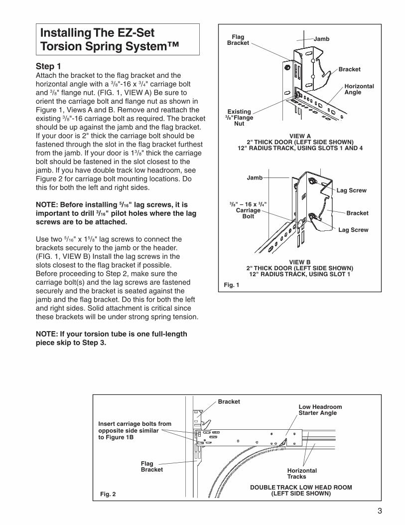
Step 1Attach the bracket to the flag bracket and thehorizontal angle with a 3/8"-16 x 3/4" carriage boltand 3/8" flange nut. (FIG. 1, VIEW A) Be sure toorient the carriage bolt and flange nut as shown inFigure 1, Views A and B. Remove and reattach theexisting 3/8"-16 carriage bolt as required. The bracketshould be up against the jamb and the flag bracket.If your door is 2" thick the carriage bolt should befastened through the slot in the flag bracket furthestfrom the jamb. If your door is 13/8" thick the carriagebolt should be fastened in the slot closest to thejamb. If you have double track low headroom, seeFigure 2 for carriage bolt mounting locations. Dothis for both the left and right sides.
NOTE: Before installing 5/16" lag screws, it isimportant to drill 3/16" pilot holes where the lagscrews are to be attached.
Use two 5/16" x 15/8" lag screws to connect thebrackets securely to the jamb or the header.(FIG. 1, VIEW B) Install the lag screws in theslots closest to the flag bracket if possible.Before proceeding to Step 2, make sure thecarriage bolt(s) and the lag screws are fastenedsecurely and the bracket is seated against thejamb and the flag bracket. Do this for both the leftand right sides. Solid attachment is critical sincethese brackets will be under strong spring tension.
NOTE: If your torsion tube is one full-lengthpiece skip to Step 3.
Fig. 1
FlagBracket
Jamb
Bracket
HorizontalAngle
VIEW A2" THICK DOOR (LEFT SIDE SHOWN)
12" RADIUS TRACK, USING SLOTS 1 AND 4
VIEW B2" THICK DOOR (LEFT SIDE SHOWN)12" RADIUS TRACK, USING SLOT 1
Existing3/8"Flange
Nut
3/8" – 16 x 3/4"Carriage
Bolt Bracket
Lag Screw
Jamb
Lag Screw
Fig. 2
Low HeadroomStarter Angle
HorizontalTracks
Bracket
Insert carriage bolts fromopposite side similarto Figure 1B
FlagBracket
DOUBLE TRACK LOW HEAD ROOM(LEFT SIDE SHOWN)
4
NOTE: Refer to standard instruction manual todetermine the radius of your track.
Step 2Push the two torsion tube sections firmly into thecoupler.
NOTE: There are sets of two opposing holes ineach end of the coupler. When attaching thecoupler to each tube be sure to use the twoholes that are on the same side of the coupleras shown in Figure 4.
After the tubes are inserted completely into thecoupler, drill one 3/16" pilot hole in each torsiontube using the coupler holes as a guide. Fastenthe coupler to the tube with (2) #14 x 5/8" sheetmetal screws. (FIG. 4) Make sure the screws aresecure. Be careful not to over tighten screws, asthis could cause the hole to be stripped out.
Step 3Lay the spring(s) flat on the floor. Measure thelength of each spring as shown in Figure 5, andrecord each length in the space provided. You willneed to refer to this length in Step 7.
Fig. 4 TUBE COUPLER (IF SUPPLIED)
TubeCoupler
TorsionTubes
#14 x 5/8" SheetMetal Screw
Fig. 5
GreenSpring Plug
Left Side Spring Length
OrangeSpring Plug
Right Side Spring Length
(RECORD LENGTH HERE)
(RECORD LENGTH HERE)
Left Spring
Right Spring
Fig. 5A DETAIL VIEW
Set Cone
End ofSpring
End ofSpring
Spring Plug
Spring Plug
End ofSpring
End ofSpring
5
TWO SPRING SYSTEM
Slide the spring(s), drums, winding unit(s), andend bearing support (if supplied) onto the torsiontube as shown in Figures 6 and 7. Alignment maybe required before the tube will pass throughspring spacer inside the spring.
If you have one spring see Figure 6 for theconfiguration of the components on the torsiontube. All “green” components MUST be put on theleft side of the tube. Make sure the end bearingsupport is oriented so that the bearing is facingtoward the right drum.
If you have two springs see Figure 7 for theconfiguration of the components on the torsiontube. All “green” components MUST be put on theleft side of the tube and all “orange” componentsMUST be put on the right side of the tube. Thetorsion tube coupler will be located between thetwo springs if so equipped.
The drums should be oriented so that the slotsare facing away from the winding unit(s) and theend bearing support (if supplied) as shown inFigure 8, Views A and B. The drums are desig-nated as left side and right side by the letters “L”and “R” respectively found near the cable slot.
Fig. 7
TorsionTube
Right Side WindingUnit (Orange Label)
Left Side Torsion Spring(Green Spring Plug)
Left SideDrum (Green)
Right SideDrum (Orange)
Right SideTorsion Spring(Orange Spring
Plug)Left Side Winding Unit
(Green Label)
VIEW BRIGHT SIDE SHOWNFig. 8
View ALeft side shown
Letter “L”
Left Side Drum(Marked with Green Paint)
Cable Slot
Left SideWinding Unit
Letter “R”
Right Side Drum(Marked with Orange Paint)
Cable Slot
Right SideWinding Unit
ONE SPRING SYSTEM
Right HandDrum (Orange)
SetCone
EndBearingSupport
Fig. 6
Left SideDrum (Green)
TorsionTube
Left SideWinding Unit(Green Label)
Left Side TorsionSpring (GreenSpring Plug)
6
NOTE: IF YOU NEED TO DISCONNECT THESPRING PLUG FROM THE WINDING UNITTAKE EXTRA CARE. To remove the springfrom the winding unit, two small flat-headedscrewdrivers will be required. Two tabs mustbe released, but only one tab is accessible ata time. Depress the accessible tab with a smallscrewdriver. To prevent the tab from re-locking,place a second screwdriver between the springplug and winding unit near the released tab.Wind the winding unit until the other tab canbe accessed. Depress the second tab with asmall screwdriver. Make sure both tabs havebeen released. Gently pull the spring fromthe winding unit.
After all of the components are on the tube, thespring plug should be inserted into the windingunit. Ensure that the spring plug and the windingunit have the same color code before snappingthem together. Line up both ears on the springplug with the two slots in the winding unit andpush them together. (Figure 9, Views B, C and D)Slide the components toward the center ofthe tube to expose 12" of each end of the tube.
Make sure that both ears of the spring plugare fully intact and engaged into the windingunit slots. Be certain that both of the tabs inthe winding unit slot engage with the springplug and that the connection between thespring plug and the winding unit is securebefore proceeding.
Fig. 9
VIEW B
VIEW C
Winding Unit LabelLeft Side (Green)
Left Side SpringPlug Ear (Green)
VIEW D
Winding UnitSlots & Tabs
Winding Unit LabelRight Side (Orange)
Right Side SpringPlug Ear (Orange)
Winding UnitSlots & Tabs
LEFT SIDE SHOWNAFTER INSERTION
RIGHT SIDE SHOWNBEFORE INSERTION
LEFT SIDE SHOWNBEFORE INSERTION
Tabs(Press Hereto Remove Spring
PlugWinding
Unit
Spring
VIEW A
7
Step 4Carefully lift up the torsion tube and componentsand place the ends of the tube in the cradle ofeach bracket. Pull the tube away from the bracketto slide the drum in between the bracket legs, andengage the winding unit rails in the bracket slot.(FIG. 10, VIEW A) Push the winding unit rails intothe bracket until the unit bottoms out.
If you have a door with two springs, go to the rightside and repeat the procedure for installing thewinding unit in the bracket.
If you have a door with only one spring, go to theright side and install the end bearing support. Theend bearing support is installed in the samemanner as the winding unit. Pull the tube back justfar enough to place the drum between the legs ofthe bracket. Do not pull the tube further thanneeded to move the end bearing support anddrum into place, as damage may occur to a unitthat is engaged on the other side. Line up theend bearing support rails (making sure that theorientation feature is facing away from thebracket) and push it into the bracket until itbottoms out. (FIG. 10, VIEW B)
Center the tube as equally as possible betweenthe brackets, so that an equal amount of the tubeis extending from each side.
Step 5 (Doors over 10' wide only)
NOTE: Before installing 1/4" lag screws, it isimportant to drill 1/8" pilot holes where the lagscrews are to be attached.
Snap the center support onto the center of thetorsion tube (or coupler if present). Fasten thesupport with two 1/4" x 1" lag screws to the headerabove the center of the door. The lag screwsshould be located at opposite corners of thecenter support as shown in Figure 11. Positionand shim the mounting location as required tomake the tube straight. Check the distance fromthe top of the door and the wall or header to thetube along the length of the door to make sure thetube is straight and level.
Fig. 11
TorsionTubeLag
Screws
Header or WoodAnchor pad
CouplerTorsionTube
Fig. 10
VIEW ALEFT SIDE SHOWN
Winding Unit
VIEW BSINGLE SPRING – RIGHT SIDE SHOWN
Bracket
Bearing
Rails
Orientation FeaturesEnd Bearing
Support
Bracket
Bearing
Rails
NOTE: The drums and torsion tube are removedfrom Figure 10, View A and Figure 10, View Bfor clarity.
Center Support(Required on doorsover 10' wide only)
8
Step 6Install the included 1/4" insert bit (or a 7/16" socket)in a medium duty drill: 1000-2500 RPM, (2-4 AMP)variable-speed and reversible. Set the drill toFORWARD (clockwise as you point the drill awayfrom you). Keep this drill and a 3/16" hex key handyfor Steps 8 and 9.
If the stripe on each spring is not facing towardyou as shown in Figure 12, engage the drill withthe 1/4" insert bit (or 7/16" socket) into drive shaft ofthe winding unit to rotate the spring until the stripeis facing you. (FIG. 12)
NOTE: The 1/4" insert bit shown in Figure 12 issecured in a drill chuck, but the drill is notshown.
Step 7Holding the tube in place, compress the left sidespring completely against the winding unit, andthen release the spring. Measure and adjust thelength of the spring and match the length yourecorded in Figure 5.
DO NOT STRETCH SPRING(S) BEFORETIGHTENING SET SCREWS. Stretching thesprings could cause the loss of spring tensionand possibly allow the door to fall. The lengthof the spring on the shaft should NOT exceedthe relaxed spring length recorded in Step 3on page 4 of the EZ-Set Torsion Spring System™Instructions.
NOTE: Be sure to hold the tube in position afteryou have tightened the spring set screws. Anysliding of the tube from this point on will affectthe length of the springs.
Tighten both set screws in the set cone to thetorsion tube. Use a 3/8" wrench if the springs aresupplied with square head set screws as shownin Figure 13, View A. Use a 3/16" hex wrench ifsupplied with internal set screws as shown inFigure 13, View B. CAUTION: When resistance isencountered while tightening the set screw, thescrew has made contact with the tube. Set screwsshould be turned from 3/4 to one full turn after theyhave made contact with the tube. Additional turnsmay damage the tube.
Fig. 13
View Bset cone shown withinternal set screws
View Aset cone shown with
square head set screws
External SetScrews
Torsion Spring
Set Cone
TorsionTube
Internal SetScrews
Torsion Spring
Set Cone
TorsionTube
Fig. 12
If you have a door with two springs, repeat theabove procedure for the right side spring.
NOTE: If you will be installing the optionalspring cover, you will need to have torsionsprings equipped with internal set screws.See Step 10 for more information.
ClockwiseWindingDirection
9
Step 8NOTE: Be careful not to shift the tube left orright during this step as this will disturb thegap set in the spring(s).
Starting with the left side, pull the lift cable up fromthe safety bottom bracket behind the rollers andinside of the jamb brackets. Bring it between thelegs of the bracket and behind the drum and insertthe cable lug into the drum slot. (FIG. 14, VIEWSA & B) Make sure that both set screws are flush orbelow the surface of the cable grooves BEFOREsecuring the drum. Take up the cable slack byturning the drum by hand. Make sure the cable ispulled tightly into the drum grooves and the drumis against the bearing in the winding unit, thentighten the most accessible set screw in the drum(only one of two need to be tightened) using a 3/16"hex wrench. CAUTION: When resistance isencountered while tightening the set screw, thescrew has made contact with the tube. Set screwsshould be turned from 3/4 to one full turn after theyhave made contact with the tube. Additional turnsmay damage the tube. While maintaining cabletension, use the drill (turning clockwise as inFigure 12) to wind the spring 1 or 2 turns. Thespring tension will maintain the proper cabletension when you let go.
Go to the right side to secure the right side drum.Pull the cable up between the legs of the bracket,insert the cable lug in the drum slot, and take upthe cable slack by turning the drum. Before secur-ing the right side drum, pull the tube toward theright side to make sure there is no gap betweenthe left drum and left bearing. Slide the right drumagainst the right bearing and secure the drum.There should be 1/16" maximum gap between thedrums and the bearings on each side. Tighten themost accessible set screw down to secure theright drum using a 3/16" hex wrench. CAUTION:When resistance is encountered while tighteningthe set screw, the screw has made contact withthe tube. Set screws should be turned from 3/4 toone full turn after they have made contact with thetube. Additional turns may damage the tube.
NOTE: Verify that the drum marked with theletter “L” is on the left side (FIG. 14, VIEW A)and the drum marked with the letter “R” is onthe right side. (FIG. 14, VIEW B)
Fig. 14
VIEW BRIGHT SIDE SHOWN
VIEW ALEFT SIDE SHOWN
Cable Lug
Letter “L”
Drum Slot
Drum Slot
CableLug
Letter “R”
Set ScrewLocation
10
Step 9:Install the tube retainer as shown in Figure 15.Attach the tube retainer to the EZ-Set TorsionSpring System™ bracket with a 3/8" - 16 x 3/4"carriage bolt. Be sure to position the carriage boltand flange nut as shown in Figure 15. Be sure toinstall a tube retainer on both the left and rightsides of the door.
To avoid personal injury, do not rest handor any other part of your body on the springor any part of the EZ-Set Torsion SpringSystem™ while tensioning or untensioningthe spring.
During winding, operate the drill at HALFSPEED until the required number of windsis reached. If additional winding is requiredor the system has to be completely unwound,wait AT LEAST FIVE MINUTES betweenconsecutive winds/unwinds. If for any reasonthe unit begins to resist winding STOP windingat once and wait AT LEAST FIVE MINUTESbefore continuing. Failure to follow theseinstructions may result in damage to theunit, the rapid release of spring energy, orpersonal injury.
To remove ALL tension from the spring,unwind (drill in reverse/counterclockwise)until the spring paint stripe is a singlestraight line and the lift cables are slack.
Only adjust the number of spring winds whenthe door is completely closed.
Fig. 15
TubeRetainer
Bracket
CarriageBolt and
Flange Nut
LEFT SIDE SHOWN
11
Step 10:Engage the drill with the 1/4" insert bit (or 7/16"socket) into the drive shaft of the winding unit towind the spring. See Table C for the total numberof winds required for your spring(s).
If you have a door with one spring:After securing the left and right drums, finishwinding the left spring to the specified number ofwinds.
If you have a door with two springs:After securing the left and right drums, there willbe one or two winds on the left spring. Proceedwith winding the right side to the specified numberof winds. Go to the left side and finish windingthe spring to the specified number of winds.
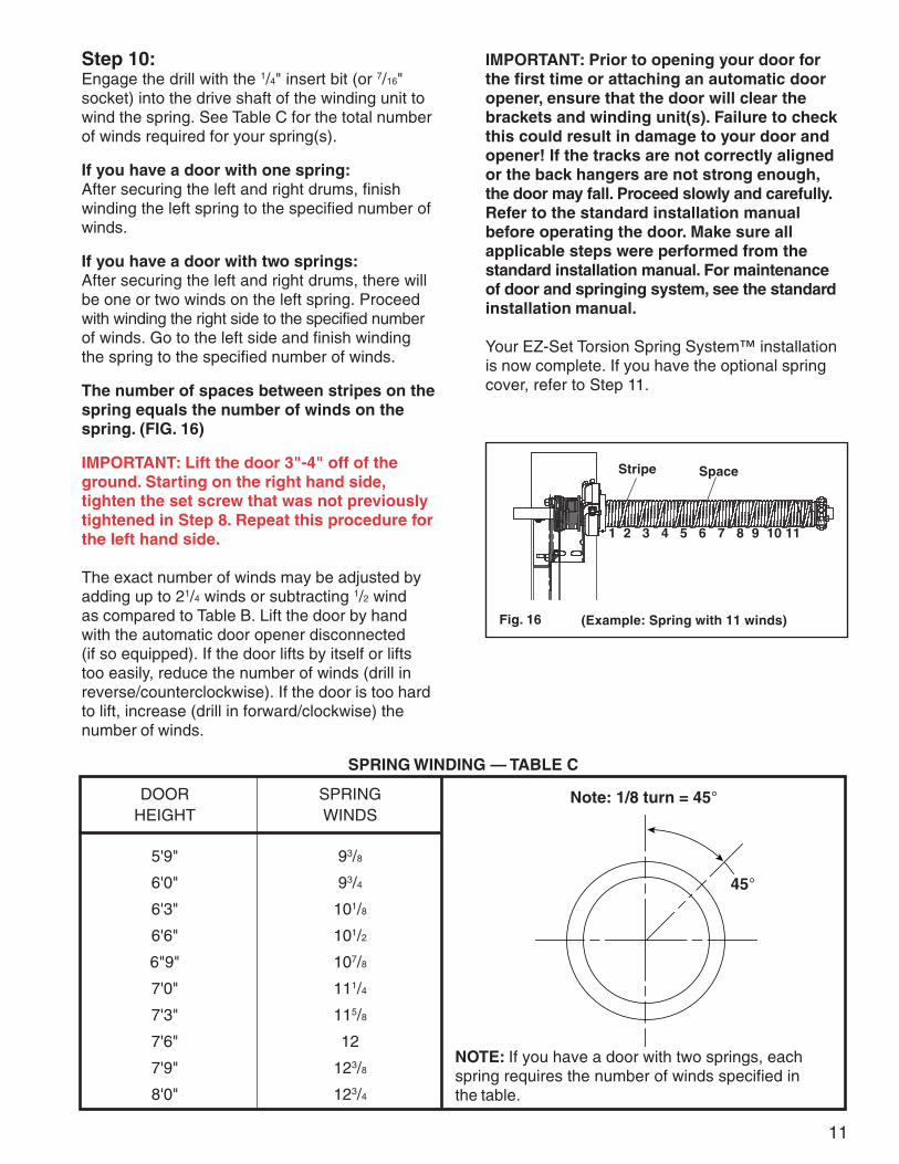
The number of spaces between stripes on thespring equals the number of winds on thespring. (FIG. 16)
IMPORTANT: Lift the door 3"-4" off of theground. Starting on the right hand side,tighten the set screw that was not previouslytightened in Step 8. Repeat this procedure forthe left hand side.
The exact number of winds may be adjusted byadding up to 21/4 winds or subtracting 1/2 windas compared to Table B. Lift the door by handwith the automatic door opener disconnected(if so equipped). If the door lifts by itself or liftstoo easily, reduce the number of winds (drill inreverse/counterclockwise). If the door is too hardto lift, increase (drill in forward/clockwise) thenumber of winds.
Fig. 16
Stripe Space
(Example: Spring with 11 winds)
1 2 3 4 5 6 7 8 9 10 11
DOOR SPRINGHEIGHT WINDS
5'9" 93/8
6'0" 93/4
6'3" 101/8
6'6" 101/2
6"9" 107/8
7'0" 111/4
7'3" 115/8
7'6" 12
7'9" 123/8
8'0" 123/4
Note: 1/8 turn = 45°
45°
NOTE: If you have a door with two springs, eachspring requires the number of winds specified inthe table.
SPRING WINDING — TABLE C
IMPORTANT: Prior to opening your door forthe first time or attaching an automatic dooropener, ensure that the door will clear thebrackets and winding unit(s). Failure to checkthis could result in damage to your door andopener! If the tracks are not correctly alignedor the back hangers are not strong enough,the door may fall. Proceed slowly and carefully.Refer to the standard installation manualbefore operating the door. Make sure allapplicable steps were performed from thestandard installation manual. For maintenanceof door and springing system, see the standardinstallation manual.
Your EZ-Set Torsion Spring System™ installationis now complete. If you have the optional springcover, refer to Step 11.
12
VIEW BSNAP CLOSED
Step 11 Optional Cover InstallationSnap the cover support over the torsion tube nextto the set cone with the open ribbed end facingtoward the set cone. (FIG. 17) If not already done,snap one edge of the two halves of the covertogether. (FIG. 18, VIEWS A & B) Spread the twohalves of the cover to go over the spring. Engagethe projections on the winding unit and the coversupport with the cover tube. Snap the open edgeof the cover closed by pinching the locking featurebetween your fingers and running them down thelength of the cover. (FIG. 19) If your door has twosprings, repeat the same procedure for the rightside.
IMPORTANT: In order to install the springcover, the set cone must be equipped withinternal set screws as shown in Figure 13,View B. If your spring has square head setscrews, you must remove all spring tensionand replace them with internal set screws. Ifyou did not receive screws with your springcover, please call the consumer hotline.