Page 1
EZ BarSmall Internal Machining
Easy Adjustment and High Precision for a Wide Range of Machining Applications
EZB EZ Bar PLUS
Internal Turning
Internal Grooving Internal Threading
EZB
EZG EZTEZFG
EZBF
EZBT EZBP
EZVB EZBC
EZ Bar PLUSNew PVD CoatingPR1725Boring
Internal Grooving Internal ThreadingFace Grooving
90 Degree Lead Angle
Back Boring Copying
Internal Facing Internal Prof iling
45 Degree Chamfering
EZ Bar SeriesSmall Internal Machining
The EZ Bar prevents deviation with high-rigidity clamping
Unique design provides a smooth supply of coolant
Large tooling lineup for a wide application range
NEW
NEW
NEW
Page 2
1
P19 ~ 20
Chipbreakers for Various Applications
Bar Tolerance Off set (WF) Longitudinal Direction (L)
Cutting Edge Height (Y) Min. Bore Dia.
HP 0.025 mm 0.05 mm 0.05 mm / 0 mm
Same as Shank Dia.
ST 0.06 mm 0.1 mm 0.06 mm / 0 mm
Different from Shank Dia.
Chipbreakers
H 1st Recommendation General PurposeLong type available
GW05 Insert Grade for Aluminum Machining Available
P5 ~ 7
P8
P5 , 7
ap = 0.2 mm or greater
FFinishing Sharpness Oriented
ap = 0.2 mm or less
Without Chipbreaker
NBHigh Precision Solid Bar with Convenience of Indexable InsertsReduce Machining Costs
EZ Bar PLUS
Minimum Bore Diameter 5 mm
Indexable EZ Bar
L
30°W
FY
ST (Cost-oriented)HP (Precision-oriented)
Large Tooling Lineup for a Wide Application Range1
Can be used for boring, back boring, internal profiling, internal grooving, face grooving and threading
Large lineup of sleeves for various tooling applications
Internal Turning
Small Internal Machining
EZ Bar SeriesMin. Bore Dia. ø2- Easy Adjustment and High PrecisionLarge Tooling Lineup for a Wide Application Range
EZB P5 ~ 8
Select the HP bar for high precision and the ST bar for cost reduction(tolerances are dif ferent)
Boring
Page 3
2
EZBT P10EZVB P10
EZBP P11 EZBC P12
45°
45°
EZBF P9
Internal Turning
Back BoringInternal Facing Internal Prof iling
Copying 45 Degree Chamfering
90 Degree Lead Angle
AlTiN/AlCrN Nano laminated f ilm with superior wear resistance and adhesion resistance Excellent surface f inish and long tool life
Applicable to various workpiece materials High machining stability
Excellent oxidation resistance. Superior high temperature properties maintains good performance in steel, stainless steel and free-cutting steel
Tough micro-grain carbide substrate provides stable machining
Superior Wear and Chipping Resistance Excellent Surface Finish
High hardness with nano laminated f ilm layer propertiesInternal stress optimization reduces chipping
Special surface layer with great lubricity reduces adhesion
Newly developed PVD coating PR1725 added to EZB boring bar
High-lubricity uniquesurface layerHigh aluminum content AlTiN layerHigh hardness / Oxidation resistance
Optimized AlCrN layerSuperior adhesion resistance
Tough micro-grain carbide substrateHigh stability
Wear Coefficient Comparison(Internal evaluation)
DOWN
37%
Conventional A Conventional BPR1725
Wea
r Coe
f f ic
ient
0.80.70.6
0.40.5
0.20.3
0.10
<Reduces cracking>Reduces abnormal damages such as chipping because of increased lamination layer with a thinner gap than conventional coatings
NEW
NEW NEW
MEGACOAT NANO PLUS Provides Better Solutions
PR1725
CustomerChallenges
Cost Reduction with Longer
Tool Life
Integrating Tools for Steel and
Stainless Steel
Requires Better Surface Finish
Vc = 50 m/minap = 0.2 mmf = 0.045 mm/revWetEZBR035035HP-015F PR1725
EZ Bar PR1725
Conventional C
SOLUTION
Conventional
18,000 pcs/edge
6,300 pcs/edge
SOLUTION 1 Improved machining efficiency. 2.8 times longer tool life
(User Evaluation)
The EZ bar (PR1725) showed 2.8 times longer tool life than the conventional C
Automotive Parts (S45C) x2.8Tool Life
Creates a f inished surface against the bore face
No up facingUnmachined portion Up facing is required
Flat 90°surface90°
General Boring 90°Lead Angle Boring
Max. D.O.C. : 1.0 mm (ø 3.0)
Page 4
3
EZG P15
EZFG P16 EZT P17 ~ 18
Internal Grooving and Threading
Sleeves
Internal Grooving
Face Grooving Internal Threading
EZGEZGR040040-200
(Groove Width 2mm)
f (mm/rev) 0.01 0.02 0.03
EZGEZGR040040-200
(Groove Width 2mm)
f (mm/rev) 0.01 0.02
S45C
SUS304
Cutting Conditions : Vc = 80 m/min, Groove depth 1.0 mm (ap = 0.2 x 5 times), Wet
Cutting Conditions : Vc = 60 m/min, Groove depth 1.0 mm (ap = 0.2 x 5 times), Wet
Chip Evacuation (Internal evaluation)
Select between three types of sleeves
EZH-CTWith EZ Adjust Structure Coolant-Through
EZH-HPWith EZ Adjust Structure
EZH-STWithout EZ Adjust StructureFor Cost Oriented Machining
How to Select Sleeves
Minimum Bore Diameter 3 mmAvailable for Threading M4 Metric Screw Threads
Two diff erent overhang lengths (LU) are available
Short type with higher rigidity andchattering resistance
Short Type (Indicated with "S" at the end of description)
Standard Type (Description: - )
Smooth coolant flow due to special head design
Coolant
Coolant
Page 5
4
Adjustable Overhang Length (EZ Adjust Structure)2
For CT sleeves with coolant holes and HP sleeves with positioning function, the overhang length can be set by moving adjustment pins
Overhang Length
Adjustment Pin is Moveable
Bar End (Slant)
Adjustment Pin
Minimized Deviation of Cutting Diameter3
The adjustment pin prevents the bar from rotating during machining
EZ Bar Competitor
Cutt
ing
Dia
met
er D
evia
tion (μm) 5
0
−5
−10
−15
−20
Cutting Time (min)0 5 10 15 20 25 30 35
2nd Time3rd Time
1st Time
4th Time
Large def lection after replacing bar four times
Cutt
ing
Dia
met
er D
evia
tion (μm) 5
0
−5
−10
−15
−20
Cutting Time (min)0 5 10 15 20 25 30 35
2nd Time3rd Time
1st Time
4th Time
Competitor AEZ Bar
Cutting Conditions : Vc = 66 m/min, ap = 0.1 mm, f = 0.02 mm/rev, Wet (oil) Workpiece : SK4
Cutting Diameter Deviation Comparison (Internal evaluation)
Fixed by screws from above
Adjustment pin prevents bar rotation
Fixed by screws from above
Page 6
5°
11° 7°
14°RE 1
5° 5°
LFLU
30°
RE DCONDCON
H
WF2
WFDM
IN
0°
31°
18°
7°5°
RE 1
5°5°
LFLU
30°
WF2RE
H
DMIN
WF
0°
Chipbreaker Detail
Chipbreaker Detail
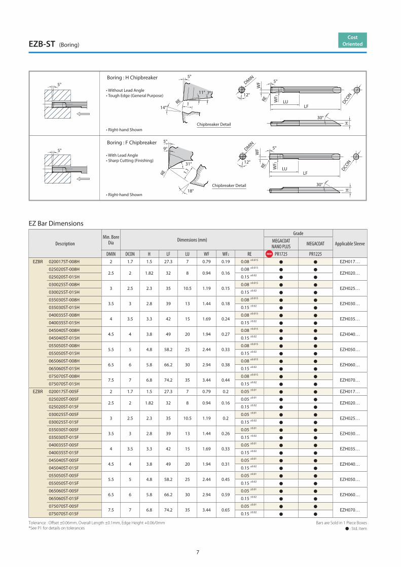
Boring : H Chipbreaker
Boring : F Chipbreaker
• Right-hand Shown
• Right-hand Shown
• Without Lead Angle• Tough Edge (General Purpose)
• With Lead Angle• Sharp Cutting (Finishing)
5
EZ Bar Dimensions
Description
Min. Bore Dia. Dimensions (mm)
Grade
Applicable SleeveMEGACOATNANO PLUS MEGACOAT Carbide
DMIN DCON H LF LU WF WF2 REPR1725 PR1225 GW05
R L R L R LEZB R/L 020020HP-008H 2 2 1.8 32 8 0.85 0.25 0.08 ±0.015 EZH020…
025025HP-008H2.5 2.5 2.3 35 10.5 1.1 0.25
0.08 ±0.015
EZH025…025025HP-015H 0.15 ±0.02
030030HP-008H3 3 2.7 38.9 13 1.35 0.3
0.08 ±0.015
EZH030…030030HP-015H 0.15 ±0.02
035035HP-008H3.5 3.5 3.2 41.9 15 1.6 0.4
0.08 ±0.015
EZH035…035035HP-015H 0.15 ±0.02
040040HP-008H4 4 3.6 48.8 20 1.85 0.4
0.08 ±0.015
EZH040…040040HP-015H 0.15 ±0.02
045045HP-008H4.5 4.5 4.1 51.1 22.5 2.1 0.5
0.08 ±0.015
EZH045…045045HP-015H 0.15 ±0.02
050050HP-008H5 5 4.6 58.1 25 2.35 0.5
0.08 ±0.015
EZH050…050050HP-015H 0.15 ±0.02
060060HP-008H6 6 5.6 66.1 30 2.85 0.6
0.08 ±0.015
EZH060…060060HP-015H 0.15 ±0.02
070070HP-008H7 7 6.3 73.8 35 3.3 0.7
0.08 ±0.015
EZH070…070070HP-015H 0.15 ±0.02
080080HP-008H8 8 7.2 84.8 40 3.75 0.8
0.08 ±0.015
EZH080…080080HP-015H 0.15 ±0.02
EZBR 020020HP-005F 2 2 1.8 32 8 0.85 0.25 0.05 ±0.01 EZH020…
025025HP-005F2.5 2.5 2.3 35 10.5 1.1 0.3
0.05 ±0.01
EZH025…025025HP-015F 0.15 ±0.02
030030HP-005F3 3 2.7 38.9 13 1.35 0.4
0.05 ±0.01
EZH030…030030HP-015F 0.15 ±0.02
035035HP-005F3.5 3.5 3.2 41.9 15 1.6 0.5
0.05 ±0.01
EZH035…035035HP-015F 0.15 ±0.02
040040HP-005F4 4 3.6 48.8 20 1.85 0.5
0.05 ±0.01
EZH040…040040HP-015F 0.15 ±0.02
045045HP-005F4.5 4.5 4.1 51.1 22.5 2.1 0.7
0.05 ±0.01
EZH045…045045HP-015F 0.15 ±0.02
050050HP-005F5 5 4.6 58.1 25 2.35 0.7
0.05 ±0.01
EZH050…050050HP-015F 0.15 ±0.02
060060HP-005F6 6 5.6 66.1 30 2.85 0.9
0.05 ±0.01
EZH060…060060HP-015F 0.15 ±0.02
070070HP-005F7 7 6.3 73.8 35 3.3 1
0.05 ±0.01
EZH070…070070HP-015F 0.15 ±0.02
080080HP-005F8 8 7.2 84.8 40 3.75 1
0.05 ±0.01
EZH080…080080HP-015F 0.15 ±0.02
High PrecisionEZB-HP (Boring)
NEW
Bars are Sold in 1 Piece Boxes : Std. Item
Tolerance (of the reference pin) : Offset ±0.025mm, Overall Length ±0.05mm, Edge Height +0.05/0mm*See P1 for details on tolerances
Page 7
6
EZ B R 020 020 HP - 008 H
EZ Bar Dimensions
Extended Reach (…HP…-LT) Bar Overhang Length T (mm)
Bars are Sold in 1 Piece Boxes : Std. Item
Tolerance : Offset ±0.025mm, Overall Length ±0.05mm, Edge Height +0.05/0mm*See P1 for details on tolerances. * In case of overhang length mentioned in italics, modified insert is required
BarSleeve
EZB ••• HP EZB ••• ST HPB ••• (EOL)
EZH ••• CT*1
(Compatible)
EZH ••• HP*1
(Compatible)
EZH ••• ST*1 *2
(Compatible)
PSH ••• (EOL)*1
(Compatible)*1
(Compatible)
*1 : Some diameters of conventional tip bars are incompatible*2 : Use conventional tip bars without adjustment pins. The overhang length of bar is not adjustable
Description
Min. BoreDia. Dimensions (mm)
Grade
Applicable SleeveMEGACOAT
DMIN DCON H LF LU*Overhang Length
WF WF2 RE PR1225No.1 No.2 No.3 No.4
EZBR 020020HP-008H-LT 2 2 1.8 36 12 12.5 8.5 - - 0.850.25
0.08 ±0.015
EZH020…
025025HP-008H-LT 2.5 2.5 2.3 39.5 15 15.5 11.5 - - 1.1 EZH025…
030030HP-008H-LT 3 3 2.7 47.9 18 22.5 18.5 14.5 - 1.35 0.3 EZH030…
035035HP-008H-LT 3.5 3.5 3.2 51.9 21 25.5 21.5 17.5 - 1.60.4
EZH035…
040040HP-008H-LT 4 4 3.6 60.8 28 32.5 28.5 24.5 20.5 1.85 EZH040…
050050HP-008H-LT 5 5 4.6 73.1 35 40.5 35.5 30.5 25.5 2.35 0.5 EZH050…
060060HP-008H-LT 6 6 5.6 83.1 42 47.5 42.5 37.5 32.5 2.85 0.6 EZH060…
5°
11° 7°
14°RE
1
5°
DCON
5°
LFLU
WF
RE WF2
DMIN
0°
30°
H
Boring : H Chipbreaker
• Right-hand Shown
• Without Lead Angle• Tough Edge (General Purpose)
Chipbreaker Detail
5°
How to Distinguish Bars EZ Bar Compatibility
DescriptionAdjustment Pin Setting
No.1 No.2 No.3 No.4EZBR 020020HP-008H-LT 12.5 8.5 - -
025025HP-008H-LT 15.5 11.5 - -
030030HP-008H-LT 22.5 18.5 14.5 -
035035HP-008H-LT 25.5 21.5 17.5 -
040040HP-008H-LT 32.5 28.5 24.5 20.5
050050HP-008H-LT 40.5 35.5 30.5 25.5
060060HP-008H-LT 47.5 42.5 37.5 32.5
* In case of overhang length mentioned in italics, modified insert is required
No.1 No.3No.2 No.4
T
Chip Pocket Angles are Different EZ Bar Compatible with Conventional Tip Bars
HP (EZB-HP) ST (EZB-ST)
Chip Pocket
Flat Portion of the Shank0°
Chip Pocket
Flat Portion of the Shank
12°
High Precision
Extended Reach(...HP...-LT)EZB-HP (Boring, Long Type)
ChipbreakerH Chipbreaker
(Without Lead Angle)H-LT : Chipbreaker (Extended Reach)
F Chipbreaker (With Lead Angle)
NB : Without Chipbreaker
Min. Bore Dia.
020 : 2 mm
025 : 2.5 mm
Shank Dia.
020 : 2 mm
025 : 2.5 mm
Precision
HP : High Precision
ST : Standard
Corner-R(RE)
008 : 0.08 mm
015 : 0.15 mm
Application
B : Boring Bar
Bar Hand
R : Right-hand
L : Left-hand
Bar Symbol (EZ Bar)
EZ Bar Identification System
Page 8
5°
30°
WF2
5°
RE DCONH
WF
LULF
DMIN
12°
5°
11° 7°
14°RE
1
5°
LU
30°
5°
RE DCONH
WF2
WF
LF
DMIN
12°
31°
18°
9°
5°
RE 1.1
Boring : H Chipbreaker
Boring : F Chipbreaker
• Right-hand Shown
• Right-hand Shown
• Without Lead Angle• Tough Edge (General Purpose)
• With Lead Angle• Sharp Cutting (Finishing)
Chipbreaker Detail
Chipbreaker Detail
7
DescriptionMin. Bore
Dia Dimensions (mm)Grade
Applicable SleeveMEGACOATNANO PLUS MEGACOAT
DMIN DCON H LF LU WF WF2 RE PR1725 PR1225EZBR 020017ST-008H 2 1.7 1.5 27.3 7 0.79 0.19 0.08 ±0.015 EZH017…
025020ST-008H2.5 2 1.82 32 8 0.94 0.16
0.08 ±0.015
EZH020…025020ST-015H 0.15 ±0.02
030025ST-008H3 2.5 2.3 35 10.5 1.19 0.15
0.08 ±0.015
EZH025…030025ST-015H 0.15 ±0.02
035030ST-008H3.5 3 2.8 39 13 1.44 0.18
0.08 ±0.015
EZH030…035030ST-015H 0.15 ±0.02
040035ST-008H4 3.5 3.3 42 15 1.69 0.24
0.08 ±0.015
EZH035…040035ST-015H 0.15 ±0.02
045040ST-008H4.5 4 3.8 49 20 1.94 0.27
0.08 ±0.015
EZH040…045040ST-015H 0.15 ±0.02
055050ST-008H5.5 5 4.8 58.2 25 2.44 0.33
0.08 ±0.015
EZH050…055050ST-015H 0.15 ±0.02
065060ST-008H6.5 6 5.8 66.2 30 2.94 0.38
0.08 ±0.015
EZH060…065060ST-015H 0.15 ±0.02
075070ST-008H7.5 7 6.8 74.2 35 3.44 0.44
0.08 ±0.015
EZH070…075070ST-015H 0.15 ±0.02
EZBR 020017ST-005F 2 1.7 1.5 27.3 7 0.79 0.2 0.05 ±0.01 EZH017…
025020ST-005F2.5 2 1.82 32 8 0.94 0.16
0.05 ±0.01
EZH020…025020ST-015F 0.15 ±0.02
030025ST-005F3 2.5 2.3 35 10.5 1.19 0.2
0.05 ±0.01
EZH025…030025ST-015F 0.15 ±0.02
035030ST-005F3.5 3 2.8 39 13 1.44 0.26
0.05 ±0.01
EZH030…035030ST-015F 0.15 ±0.02
040035ST-005F4 3.5 3.3 42 15 1.69 0.33
0.05 ±0.01
EZH035…040035ST-015F 0.15 ±0.02
045040ST-005F4.5 4 3.8 49 20 1.94 0.31
0.05 ±0.01
EZH040…045040ST-015F 0.15 ±0.02
055050ST-005F5.5 5 4.8 58.2 25 2.44 0.45
0.05 ±0.01
EZH050…055050ST-015F 0.15 ±0.02
065060ST-005F6.5 6 5.8 66.2 30 2.94 0.59
0.05 ±0.01
EZH060…065060ST-015F 0.15 ±0.02
075070ST-005F7.5 7 6.8 74.2 35 3.44 0.65
0.05 ±0.01
EZH070…075070ST-015F 0.15 ±0.02
EZ Bar Dimensions
Bars are Sold in 1 Piece Boxes : Std. Item
Tolerance : Offset ±0.06mm, Overall Length ±0.1mm, Edge Height +0.06/0mm*See P1 for details on tolerances
EZB-ST (Boring)Cost
Oriented
NEW
Page 9
5°
30°
H
0°
DMIN 5°
LFLUW
F2
REW
F
DCON
5°
LU
30°
5°
RE DCONH
WF2
WF
LF
DMIN
12°
7°7°
<PR1225•GW05>
<KBN05M•KPD001>
• Right-hand Shown
• Right-hand Shown
EZBR030 TypeFig.2
Fig.3
Fig.1
EZBR040-EZBR070 Type
8
EZ Bar Dimensions
Bars are Sold in 1 Piece Boxes : Std. Item
Description
Min. Bore Dia Dimensions (mm)
Drawing
Grade
Applicable SleeveMEGACOAT Carbide
MEGACOATCBN
PCD
DMIN DCON H LF LU WF WF2 RE
5221RP
50WG
M50NBK
100DPK
EZBR 020017-005NB 2 1.7 1.5 27.3 7 0.79 0.2
0.05 ±0.015 Fig.1
EZH017…
025020-005NB 2.5 2 1.82 32 8 0.94 0.16 EZH020…
030025-005NB 3 2.5 2.3 35 10.5 1.19 0.16 EZH025…
035030-005NB 3.5 3 2.8 39 13 1.44 0.19 EZH030…
040035-005NB 4 3.5 3.3 42 15 1.69 0.25 EZH035…
045040-005NB 4.5 4 3.8 49 20 1.94 0.28 EZH040…
055050-005NB 5.5 5 4.8 58.2 25 2.44 0.33 EZH050…
065060-005NB 6.5 6 5.8 66.2 30 2.94 0.39 EZH060…
075070-005NB 7.5 7 6.8 74.2 35 3.44 0.45 EZH070…
EZBR 030030-003NB 3 3 2.6 38.8 13 1.25 0.3
0.035 ±0.015
Fig.2 EZH030…
040040-003NB 4 4 3.6 48.8 20 1.75
0.5
Fig.3
EZH040…
050050-003NB 5 5 4.6 58.1 25 2.25 EZH050…
060060-003NB 6 6 5.6 66.1 30 2.75 EZH060…
070070-003NB 7 7 6.6 74.1 35 3.25 EZH070…
EZBR 040040-003NB 4 4 3.6 48.8 20 1.75
0.5 0.035 ±0.015
EZH040…
050050-003NB 5 5 4.6 58.1 25 2.25 EZH050…
060060-003NB 6 6 5.6 66.1 30 2.75 EZH060…
070070-003NB 7 7 6.6 74.1 35 3.25 EZH070…
Edge Preparation
Grade Edge Preparation Notes
PR1225 • GW05 Sharp Edge –
KBN05M T00815 0.08 mm × 15° Chamfered Cutting Edge
KPD001 Sharp Edge –
EZB-NB (Boring)Without
Chipbreaker PCD · CBN
Page 10
9
Precautions
EZBF (90 Degree Lead Angle)
DCON
30°
HChipbreaker Detail
WF
90°
LULF
0°DMIN
RE WF2
2°RE
20°90°
LBB
90°
EZ Bar Dimensions
Bars are Sold in 1 Piece Boxes : Std. Item
Tolerance : Offset ±0.05mm, Overall Length ±0.05mm, Edge Height +0.05/0mm*See P1 for details on tolerances
DescriptionMin. Bore
Dia. Dimensions (mm)Grade
Applicable SleeveMEGACOATDMIN DCON H LF LU WF WF2 LBB RE PR1225
EZBFR 030030-008 3 3 2.5 37.7 12 1.2 0.45 1.5 0.08 ±0.015 EZH030…
040040-008 4 4 3.45 44.6 16 1.65 0.55 2.0 0.08 ±0.015 EZH040…
050050-015 5 5 4.3 52.7 20 2.15 0.7 2.4 0.15 ±0.02 EZH050…
060060-015 6 6 5.15 59.6 24 2.55 0.85 2.8 0.15 ±0.02 EZH060…
Min boring diameter of ø 4 : 1.9 mm front cutting edge length
Off-center Boring
Stepped hole Blind hole
1. Machining in blind hole is not recommended
3. Up facing is not recommended
Recommended Not Recommended
2. If front cutting edge exceeds beyond workpiece center line, fracturing may occurFracturing May Occur
Fracturing May Occur
90 Degree Lead Angle
• Right-hand Shown
Page 11
1.4
DCON
30°
H
DMIN
0°
LF
RE
LH
WF2
WF
52°
14°
RE
52°
Chipbreaker Detail
• Right-hand Shown
H
30°
DCON
5°
WF2
RE
LU
LF
1.50°
DMIN5°
14°
1
RE
5°
WF
Chipbreaker Detail
• Right-hand Shown
10
DescriptionMin. Bore
Dia. Dimensions (mm)Grade
Applicable SleeveMEGACOATDMIN DCON H LF LH WF WF2 RE PR1225
EZVBR 035030-010 3.5 3 2.8 38 8
0.17
0.22
0.1 ±0.015
EZH030…
045040-010 4.5 4 3.8 43 10 0.26 EZH040…
055050-010 5.5 5 4.8 50.2 12 0.29 EZH050…
065060-010 6.5 6 5.8 55.2 14 0.32 EZH060…
DescriptionMin. Bore
Dia. Dimensions (mm)Grade
Applicable SleeveMEGACOAT CarbideDMIN DCON H LF LU WF WF2 RE PR1225 GW05
EZBTR 040040-005 4 4 3.45 48.7 20 1.7 1.20.05
EZH040…
050050-005 5 5 4.3 58.7 25 2.15 1.5 EZH050…
EZ Bar Dimensions
EZ Bar Dimensions
Bars are Sold in 1 Piece Boxes : Std. Item
Bars are Sold in 1 Piece Boxes : Std. Item
0 0.02
EZVB (Boring • Internal Facing • Internal Profiling)Internal Profiling
EZBT (Back Boring)Back Boring
Page 12
11
0.6
0.3
0.1
0.02 0.03 0.05
0.6
0.3
0.1
0.02 0.03 0.05
0.6
0.3
0.1
0.02 0.03 0.05
0.6
0.3
0.1
0.02 0.03 0.05
30°
Chipbreaker Detail
APM
X
WF2
WF
RE
DMIN
LF
3°
8°
47°
7°
RE
8°
LBB
H
LU DCON
EZ Bar Dimensions
Bars are Sold in 1 Piece Boxes : Std. Item
EZBP showed better chip breaking in a wide range of machining applications compared to competitor B
EZBP showed better chip control than competitor B
DescriptionMin. Bore
Dia. Dimensions (mm)Grade
Applicable SleeveMEGACOATDMIN DCON H LF LU WF WF2 LBB RE APMX PR1225
EZBPR 020020-005-08
2 2 1.65
31.8 8
0.55 0.35 1.0 0.05±0.01 0.3 EZH020…020020-005-10 33.8 10
020020-005-12 35.8 12
030030-005-123 3 2.5
37.7 121.05 0.45 1.2 0.05±0.01 0.4 EZH030…
030030-005-15 40.7 15
040040-015 4 4 3.45 48.7 20 1.65 0.65 1.5 0.15±0.02 0.6 EZH040…
050050-015 5 5 4.3 57.8 25 2 1.1 2.2 0.15±0.02 0.8 EZH050…
060060-015 6 6 5.15 65.7 30 2.45 1.35 2.5 0.15±0.02 1 EZH060…
Recommended Cutting Conditions
Workpiece
Insert Grade(Vc : m/min)
EZBPR020020-005-08/10/12
EZBPR030030-005-12/15 EZBPR040040-015 EZBPR050050-015 EZBPR060060-015
NotesMEGACOAT ap (mm), f (mm/rev)PR1225 ap f ap f ap f ap f ap f
Carbon Steel • Alloy Steel(S45C • SCM)
30 ~ 100 ~ 0.3 ~ 0.05 ~ 0.4 ~ 0.05 ~ 0.6 ~ 0.05 ~ 0.8 ~ 0.05 ~ 1.0 ~ 0.05Wet
Stainless Steel(SUS304)
30 ~ 80 ~ 0.3 ~ 0.05 ~ 0.4 ~ 0.05 ~ 0.6 ~ 0.05 ~ 0.8 ~ 0.05 ~ 1.0 ~ 0.05
• Right-hand Shown
Cutting Conditions : Vc = 80 m/min, WetWorkpiece : S45C (ø14)EZBPR040040-015 PR1225
Cutting Conditions : Vc = 80 m/min, WetWorkpiece : S45C (ø14)EZBPR040040-015 PR1225
Chip Control Comparison (Internal evaluation)
ap (m
m)
ap (m
m)
ap (m
m)
ap (m
m)
f (mm/rev)
f (mm/rev)
f (mm/rev)
f (mm/rev)
EZBP
EZBP
Competitor B
Competitor B
Copying
Boring
Unstable Chip Control
NEW EZBP (Copying)Internal Profiling
Page 13
12
0.7
0.4
0.2
0.02 0.04 0.06
0.7
0.4
0.2
0.02 0.04 0.06
0.7
0.4
0.2
0.02 0.04 0.06
0.7
0.4
0.2
0.02 0.04 0.06
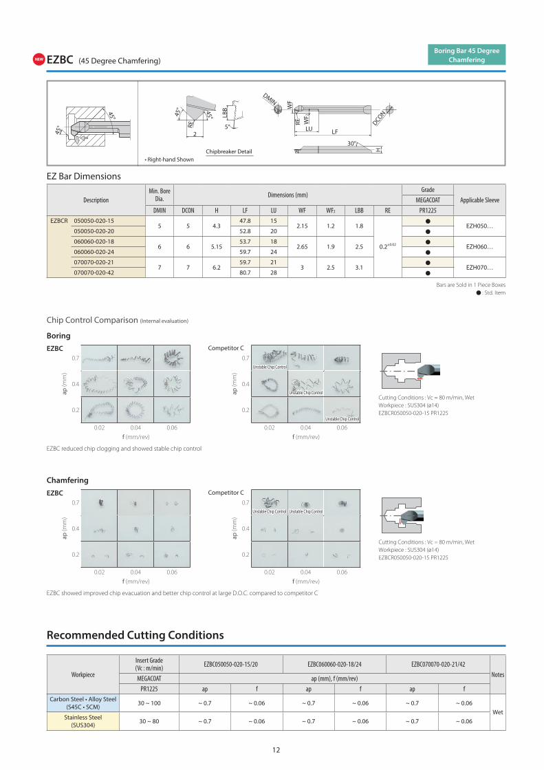
EZBC (45 Degree Chamfering)
Chipbreaker Detail
45°
RE
DMIN
25°
WF
LF
LBB
30°
RE
45°
WF2
HDCON
LU
45°
45°
EZ Bar Dimensions
Bars are Sold in 1 Piece Boxes : Std. Item
EZBC reduced chip clogging and showed stable chip control
EZBC showed improved chip evacuation and better chip control at large D.O.C. compared to competitor C
DescriptionMin. Bore
Dia. Dimensions (mm)Grade
Applicable SleeveMEGACOATDMIN DCON H LF LU WF WF2 LBB RE PR1225
EZBCR 050050-020-155 5 4.3
47.8 152.15 1.2 1.8
0.2±0.02
EZH050…050050-020-20 52.8 20
060060-020-186 6 5.15
53.7 182.65 1.9 2.5 EZH060…
060060-020-24 59.7 24
070070-020-217 7 6.2
59.7 213 2.5 3.1 EZH070…
070070-020-42 80.7 28
Recommended Cutting Conditions
Workpiece
Insert Grade(Vc : m/min) EZBC050050-020-15/20 EZBC060060-020-18/24 EZBC070070-020-21/42
NotesMEGACOAT ap (mm), f (mm/rev)PR1225 ap f ap f ap f
Carbon Steel • Alloy Steel(S45C • SCM)
30 ~ 100 ~ 0.7 ~ 0.06 ~ 0.7 ~ 0.06 ~ 0.7 ~ 0.06Wet
Stainless Steel(SUS304)
30 ~ 80 ~ 0.7 ~ 0.06 ~ 0.7 ~ 0.06 ~ 0.7 ~ 0.06
Boring Bar 45 Degree Chamfering
• Right-hand Shown
Cutting Conditions : Vc = 80 m/min, WetWorkpiece : SUS304 (ø14)EZBCR050050-020-15 PR1225
Cutting Conditions : Vc = 80 m/min, WetWorkpiece : SUS304 (ø14)EZBCR050050-020-15 PR1225
Chip Control Comparison (Internal evaluation)
ap (m
m)
ap (m
m)
ap (m
m)
ap (m
m)
f (mm/rev)
f (mm/rev)
f (mm/rev)
f (mm/rev)
EZBC
EZBC
Competitor C
Competitor C
Boring
Chamfering
Unstable Chip Control
Unstable Chip Control
Unstable Chip Control
Unstable Chip Control Unstable Chip Control
NEW
Page 14
13
Workpiece
Insert Grade(Vc : m/min) EZB020/025 Type EZB030/035 Type
NotesMEGACOATNANO PLUS MEGACOAT Carbide ap (mm), f (mm/rev)
PR1725 PR1225 GW05 ap f ap fCarbon Steel • Alloy Steel
(S45C • SCM)30 ~ 120 30 ~ 100 − ~ 0.3 ~ 0.03 ~ 0.4 ~ 0.04
WetStainless Steel
(SUS304)30 ~ 100 30 ~ 80 − ~ 0.2 ~ 0.02 ~ 0.3 ~ 0.03
Non-ferrous Metals(Aluminum • Brass)
− − ~ 100 ~ 0.3 ~ 0.05 ~ 0.4 ~ 0.06
H Chipbreaker EZB-HP •• H Type EZB-ST •• H Type
Workpiece
Insert Grade(Vc : m/min) EZB040/045 Type EZB050/055/060/
065/070/075/080 TypeNotesMEGACOAT
NANO PLUS MEGACOAT Carbide ap (mm), f (mm/rev)
PR1725 PR1225 GW05 ap f ap fCarbon Steel • Alloy Steel
(S45C • SCM)30 ~ 120 30 ~ 100 − ~ 0.45 ~ 0.07 ~ 0.5 ~ 0.1
WetStainless Steel
(SUS304)30 ~ 100 30 ~ 80 − ~ 0.35 ~ 0.05 ~ 0.4 ~ 0.07
Non-ferrous Metals(Aluminum • Brass)
− − ~ 100 ~ 0.45 ~ 0.1 ~ 0.5 ~ 0.15
Workpiece
Insert Grade(Vc : m/min) EZB020/025/030/035 Type EZB040/050/060 Type
NotesMEGACOAT ap (mm), f (mm/rev)PR1225 ap f ap f
Carbon Steel • Alloy Steel(S45C • SCM)
30 ~ 60 ~ 0.3 ~ 0.05 ~ 0.4 ~ 0.1Wet
Stainless Steel(SUS304)
20 ~ 40 ~ 0.25 ~ 0.05 ~ 0.3 ~ 0.07
H Chipbreaker (Long Type)
Recommended Cutting Conditions
Workpiece
Insert Grade(Vc : m/min)
EZB020/025 Type EZB030/035 Type EZB040/045 Type EZB050/055/060/065/070/075/080 Type
NotesMEGACOATNANO PLUS
MEGACOAT ap (mm), f (mm/rev)
PR1725 PR1225 ap f ap f ap f ap f
Carbon Steel • Alloy Steel(S45C • SCM)
30 ~ 120 30 ~ 100~ 0.2
~ 0.03~ 0.2
~ 0.05 ~ 0.3 ~ 0.07 ~ 0.3 ~ 0.07Wet
Stainless Steel(SUS304)
30 ~ 100 30 ~ 80 ~ 0.02 ~ 0.03 ~ 0.25 ~ 0.05 ~ 0.25 ~ 0.05
F Chipbreaker EZB-HP •• F Type EZB-ST •• F Type
Workpiece
Insert Grade(Vc : m/min) EZB020/025 Type EZB030/035 Type EZB040/045 Type EZB055/
065/075 TypeNotes
MEGACOAT Carbide ap (mm), f (mm/rev)PR1225 GW05 ap f ap f ap f ap f
Carbon Steel • Alloy Steel(S45C • SCM)
30 ~ 100 − ~ 0.3 ~ 0.03 ~ 0.4 ~ 0.04 ~ 0.45 ~ 0.07 ~ 0.5 ~ 0.1
WetStainless Steel
(SUS304)30 ~ 80 − ~ 0.2 ~ 0.02 ~ 0.3 ~ 0.03 ~ 0.35 ~ 0.05 ~ 0.4 ~ 0.07
Non-ferrous Metals(Aluminum • Brass)
− ~ 100 ~ 0.3 ~ 0.05 ~ 0.4 ~ 0.06 ~ 0.45 ~ 0.07 ~ 0.5 ~ 0.1
WorkpieceInsert Grade(Vc : m/min) EZB030 Type EZB040/045 Type EZB050/060/070 Type
NotesMEGACOAT CBN PCD ap (mm), f (mm/rev)KBN05M KPD001 ap f ap f ap f
Non-ferrous Metals(Aluminum • Brass)
− ~ 300 − − ~ 0.45 ~ 0.1 ~ 0.5 ~ 0.15Wet
Hard Materials(Heat-treated Steel) ~ 100 − ~ 0.07 ~ 0.03 ~ 0.10 ~ 0.05 ~ 0.15 ~ 0.07
NB Chipbreaker (without Chipbreaker)
Page 15
14
Workpiece
Insert Grade(Vc : m/min) EZBFR030030-008 EZBFR040040-008 EZBFR050050/
060060-015Notes
MEGACOAT ap (mm), f (mm/rev)PR1225 ap f ap f ap f
Carbon Steel • Alloy Steel(S45C • SCM)
30 ~ 100 ~ 0.2 ~ 0.05 ~ 0.3 ~ 0.05 ~ 0.5 ~ 0.05Wet
Stainless Steel(SUS304)
30 ~ 80 ~ 0.2 ~ 0.05 ~ 0.3 ~ 0.05 ~ 0.5 ~ 0.05
EZBF (90 Degree Lead Angle)
Workpiece
Insert Grade(Vc : m/min) EZBC050050-020-15/20 EZBC060060-020-18/24 EZBC070070-020-21/42
NotesMEGACOAT ap (mm), f (mm/rev)
PR1225 ap f ap f ap fCarbon Steel • Alloy Steel
(S45C • SCM)30 ~ 100 ~ 0.7 ~ 0.06 ~ 0.7 ~ 0.06 ~ 0.7 ~ 0.06
WetStainless Steel
(SUS304)30 ~ 80 ~ 0.7 ~ 0.06 ~ 0.7 ~ 0.06 ~ 0.7 ~ 0.06
EZBC (45 Degree Chamfering)
Workpiece
Insert Grade(Vc : m/min)
EZBPR020020-005-08/10/12
EZBPR030030-005-12/15 EZBPR040040-015 EZBPR050050-015 EZBPR060060-015
NotesMEGACOAT ap (mm), f (mm/rev)
PR1225 ap f ap f ap f ap f ap fCarbon Steel • Alloy Steel
(S45C • SCM)30 ~ 100 ~ 0.3 ~ 0.05 ~ 0.4 ~ 0.05 ~ 0.6 ~ 0.05 ~ 0.8 ~ 0.05 ~ 1.0 ~ 0.05
WetStainless Steel
(SUS304)30 ~ 80 ~ 0.3 ~ 0.05 ~ 0.4 ~ 0.05 ~ 0.6 ~ 0.05 ~ 0.8 ~ 0.05 ~ 1.0 ~ 0.05
EZBP (Copying)
Recommended Cutting Conditions
WorkpieceInsert Grade (Vc : m/min) EZBTR040 Type EZBTR050 Type
NotesMEGACOAT Carbide ap (mm), f (mm/rev)PR1225 GW05 ap f ap f
Carbon Steel • Alloy Steel(S45C • SCM)
30 ~ 100 −
~ 0.45
~ 0.07
~ 0.5
~ 0.1
WetStainless Steel
(SUS304)30 ~ 80 − ~ 0.05 ~ 0.07
Non-ferrous Metals(Aluminum • Brass)
− 30 ~ 100 ~ 0.1 ~ 0.15
EZBT (Back Boring)
WorkpieceInsert Grade (Vc : m/min) EZVB035 Type EZVB045 Type EZVB055/065 Type
NotesMEGACOAT ap (mm), f (mm/rev)PR1225 ap f ap f ap f
Carbon Steel • Alloy Steel(S45C • SCM)
30 ~ 100 ~ 0.05 ~ 0.04 ~ 0.07 ~ 0.07 ~ 0.1 ~ 0.07Wet
Stainless Steel(SUS304)
30 ~ 80 ~ 0.03 ~ 0.03 ~ 0.05 ~ 0.05 ~ 0.07 ~ 0.05
EZVB (Boring • Internal Facing • Internal Profiling)
Page 16
WF
2°
WF2
CWLU
LF
CDX
30°
HDCO
N
CW±0.0316°
DMIN
RE RE
WF
2°
WF2
CWLU
LF
CDX
30°
HDCO
N
DMIN
Fig.1 Fig.2
Chipbreaker Detail• Right-hand Shown
15
DescriptionMin. Bore
Dia. Dimensions (mm)Drawing
MEGACOAT CarbideApplicable SleevePR1225 GW05
DMIN CW±0.03 RE DCON H LF LU WF WF2 CDX R L R LEZG R/L 040040-050
4
0.5
±0.013
0.05
4 3.45 44.7 12 1.7
0
1 Fig.2 EZH040..040040-100 1.0040040-150 1.5040040-200 2.0050050-100
51.0
5 4.3 52.8
20
2.15 1.5
Fig.1
EZH050..050050-150 1.5050050-200 2.0060060-100
61.0
6 5.15 60.7 2.65
2
EZH060..060060-150 1.5060060-200 2.0070070-100
71.0
7 6.2 63.7 25
3.05
EZH070..
070070-150 1.5070070-200 2.0080070-100
81.0
3.45080070-150 1.5080070-200 2.0
EZGR 030030-050S3
0.5
±0.013
0.05
3 2.5 38.7 5 1.25
0
0.8
Fig.2
EZH030..030030-100S 1.0040040-050S
4
0.5
4 3.45 44.7 8 1.7 1 EZH040..040040-100S 1.0040040-150S 1.5040040-200S 2.0050050-100S
51.0
5 4.3 52.8
10
2.15 1.5 EZH050..050050-150S 1.5050050-200S 2.0060060-100S
61.0
6 5.15 60.7 2.65
2
EZH060..060060-150S 1.5060060-200S 2.0070070-100S
71.0
7 6.2 63.7
3.05
EZH070..
070070-150S 1.5070070-200S 2.0080070-100S
81.0
3.45080070-150S 1.5080070-200S 2.0
EZG (Internal Grooving)
Recommended Cutting Conditions
EZ Bar Dimensions
Bars are Sold in 1 Piece Boxes : Std. Item
: 1st Recommendation
Workpiece
Insert Grade(Vc : m/min) EZGR030030-...S
EZGR040040-...EZGR050050-...EZGR040040-...SEZGR050050-...S
EZGR060060-...EZGR070070-...EZGR080070-...EZGR060060-...SEZGR070070-...SEZGR080070-...S
Notes
MEGACOAT CarbidePR1225 GW05 f (mm/rev)
Carbon Steel • Alloy Steel(SxxC • SCM) 30 ~ 100 − ~ 0.02 ~ 0.03 ~ 0.05
WetStainless Steel
(SUS304) 30 ~ 80 − ~ 0.01 ~ 0.02 ~ 0.03
Non-ferrous Metals − ~ 300 − ~ 0.05 ~ 0.08
CDX : Available Grooving DepthDescription : With suffix "S" indicates a short type
Page 17
H
LFLUW
F
DAX
N
CW
CDX
RE
REDAXN
RE
RECDX
DCO
N
15°
30°
CW±0
.03
• Right-hand Shown
Edge Detail
16
EZ G R 030 030 - 050 S
EZFG (Face Grooving)
Description
Face Grooving Dia. (MIN.) Dimensions (mm) MEGACOAT Carbide
Applicable SleeveDAXN CW±0.03 RE DCON H LF LU WF CDX PR1225 GW05
R L R LEZFG R/L 050040-100
51.0
±0.013
0.05
4 3.8 45.0 12 1.91.5
EZH040..050040-150 1.5 2.0
EZFG R/L 060050-100
6
1.0
5 4.8 53.2 25 2.4
1.5
EZH050..060050-150 1.5 2.5
060050-200 2.0 3.0
EZFG R/L 080070-100
8
1.0
7 6.8 64.2 25 3.4
2.0
EZH070..080070-150 1.5 2.5
080070-200 2.03.0
080070-300 3.0
EZ Bar Dimensions
Recommended Cutting Conditions
Bars are Sold in 1 Piece Boxes : Std. Item
CDX : Available Grooving Depth
: 1st Recommendation
Workpiece
Insert Grade(Vc : m/min)
EZFGR050040-100EZFGR060050-100EZFGR080070-100
EZFGR050040-150EZFGR060050-150EZFGR080070-150
EZFGR060050-200EZFGR080070-200 EZFGR080070-300
NotesMEGACOAT CarbidePR1225 GW05 f (mm/rev)
Carbon Steel • Alloy Steel(SxxC • SCM) 30 ~ 100 − ~ 0.02 ~ 0.03 ~ 0.04 ~ 0.05
WetStainless Steel
(SUS304) 30 ~ 80 − ~ 0.01 ~ 0.02 ~ 0.02 ~ 0.03
Non-ferrous Metals − ~ 300 ~ 0.03 ~ 0.05 ~ 0.06 ~ 0.08
EZ Bar Identification System (Internal Grooving, Face Grooving)
Type
S : Short Type(LU Dimension)
Min. Bore Dia.
030 : 3 mm•••
Face Grooving Dia.
050 : 5 mm•••
Shank Dia.
030 : 3 mm•••
Groove Width
050 : 0.5 mm
100 : 1.0 mm
150 : 1.5 mm
200 : 2.0 mm
Application
G : Internal Grooving
FG : Face Grooving
Bar Hand
R : Right-hand
L : Left-hand
Bar Symbol (EZ Bar)
Page 18
0°
DCO
N
H
LFLU
WF2PDX PDX
DMIN
30°
WF
RE
PNA
PDX PDX
WF2
• Right-hand Shown
Edge Detail
17
EZT (Internal Threading)
ap & Number of Passes (Metric)
Pitch(mm)
Total ap(mm)
No. of Passes
(Times)1 Pass 2 Pass 3 Pass 4 Pass 5 Pass 6 Pass 7 Pass 8 Pass 9 Pass 10 Pass 11 Pass 12 Pass 13 Pass 14 Pass 15 Pass 16 Pass 17 Pass 18 Pass 19 Pass 20 Pass
0.5 0.3 9 0.05 0.05 0.04 0.04 0.03 0.03 0.02 0.02 0.020.7 0.42 10 0.06 0.05 0.05 0.05 0.05 0.04 0.04 0.03 0.03 0.02
0.75 0.45 10 0.06 0.06 0.05 0.05 0.05 0.04 0.04 0.04 0.03 0.030.8 0.48 11 0.06 0.06 0.05 0.05 0.05 0.04 0.04 0.04 0.03 0.03 0.03
1.00 0.61 12 0.07 0.07 0.06 0.06 0.06 0.05 0.05 0.05 0.04 0.04 0.03 0.031.25 0.77 14 0.07 0.07 0.07 0.07 0.06 0.06 0.06 0.06 0.05 0.05 0.04 0.04 0.04 0.031.50 0.93 17 0.07 0.07 0.07 0.07 0.07 0.06 0.06 0.06 0.06 0.05 0.05 0.05 0.04 0.04 0.04 0.04 0.031.75 1.1 20 0.07 0.07 0.07 0.07 0.07 0.07 0.06 0.06 0.06 0.06 0.06 0.05 0.05 0.05 0.05 0.04 0.04 0.04 0.03 0.03
ap & Number of Passes (Whitworth)
TPI(TPI/inch)
Total ap(mm)
No. of Passes
(Times)1 Pass 2 Pass 3 Pass 4 Pass 5 Pass 6 Pass 7 Pass 8 Pass 9 Pass 10 Pass 11 Pass 12 Pass 13 Pass 14 Pass 15 Pass 16 Pass 17 Pass
24 0.65 13 0.07 0.07 0.06 0.06 0.06 0.05 0.05 0.05 0.04 0.04 0.04 0.03 0.0320 0.81 15 0.07 0.07 0.07 0.07 0.06 0.06 0.06 0.06 0.05 0.05 0.05 0.04 0.04 0.03 0.0318 0.91 17 0.07 0.07 0.07 0.07 0.07 0.06 0.06 0.06 0.06 0.05 0.05 0.05 0.04 0.04 0.03 0.03 0.03
Description
Min. Bore Dia. Dimensions (mm) MEGA
COAT CarbideApplicable Threads
Metric Unif ied American National Pipe
DMIN DCON H LF LU WF WF2 PDX RE PNA PR1225 GW05 Applicable Thread Pitch (mm) Applicable Thread Pitch (TPI) Applicable
Thread Pitch (TPI)
EZTR 030025-60-002 3.0 2.5 2.3 34.5 6.0 1.19 1.0 0.5±0.01
0.02
60°
M4 or more(M3.5 or more) 0.35 ~ 0.8 No.8-32UNC
No.8-36UNF or more 36 ~ 32 – –
035030-60-002 3.5 3.0 2.8 38.4 8.4 1.44 1.2 0.6 M4.5 or more(M4.5 or more) 0.5 ~ 1.0 No.10-24UNC
No.8-36UNF or more 36 ~ 24 – –
040035-60-004 4.0 3.5 3.3 41.4 10.4 1.69 1.2 0.6
±0.01
0.04
M5 or more(M6 or more) 0.75 ~ 1.25 No.12-24UNC
No.12-28UNF or more 28 ~ 20 – –
050040-60-004 5.0 4.0 3.8 44.35 15.35 1.94 1.3 0.65 M7 or more(M6 or more) 0.75 ~ 1.5 1/4-20UNC
1/4-28UNF or more 28 ~ 18 – –
060050-60-004 6.0 5.0 4.8 52.4 19.2 2.44 1.6 0.8 M8 or more(M7 or more) 0.75 ~ 1.5 5/16-18UNC
5/16-24UNF or more 24 ~ 16 1/4NPT3/8NPT 18
070060-60-004 7.0 6.0 5.8 60.2 24.0 2.94 2.0 1.0 M9 or more(M8 or more) 0.75 ~ 1.75 3/8-16UNC
3/8-24UNF or more 24 ~ 16 1/4NPT or more 18,14
Whitworth Parallel Pipe / Tapered Pipe
EZTR 060050-55-008 6.0 5.0 4.8 52.4 19.2 2.44 1.6 0.8±0.015
0.08555°
W10 TPI 24 or more 24 ~ 20 G1/16 or more
R1/16 or more 28 – –
080070-55-008 8.0 7.0 6.8 63.2 24.0 3.44 2.0 1.0 W11 TPI 20 or more 20 ~ 18 G1/8 or more
R1/8 or more 28,19 – –
EZ Bar Dimensions
For American National Pipe (NPT), use EZTR..-60-004. See Page 18See back cover for applicable sleeves
ap & Number of Passes (Unified)
TPI(TPI/inch)
Total ap(mm)
No. of Passes
(Times)1 Pass 2 Pass 3 Pass 4 Pass 5 Pass 6 Pass 7 Pass 8 Pass 9 Pass 10 Pass 11 Pass 12 Pass 13 Pass 14 Pass 15 Pass 16 Pass 17 Pass 18 Pass
36 0.44 10 0.06 0.06 0.06 0.05 0.05 0.05 0.04 0.03 0.02 0.0232 0.5 11 0.06 0.06 0.06 0.05 0.05 0.05 0.04 0.04 0.03 0.03 0.0328 0.55 12 0.07 0.06 0.05 0.05 0.05 0.05 0.05 0.04 0.04 0.03 0.03 0.0324 0.65 12 0.07 0.07 0.06 0.06 0.06 0.06 0.05 0.05 0.05 0.05 0.04 0.0320 0.78 14 0.07 0.07 0.07 0.06 0.06 0.06 0.06 0.06 0.06 0.05 0.05 0.04 0.04 0.0318 0.88 17 0.07 0.07 0.07 0.06 0.06 0.06 0.06 0.06 0.05 0.05 0.05 0.04 0.04 0.04 0.04 0.03 0.0316 0.99 18 0.07 0.07 0.07 0.07 0.06 0.06 0.06 0.06 0.06 0.06 0.05 0.05 0.05 0.05 0.04 0.04 0.04 0.03
Bars are Sold in 1 Piece Boxes : Std. Item
Page 19
18
Application for NPT
Applicable ThreadTPI
(TPI/inch)
Internal Threading
Toolholder InsertPartial Profile Full Profile
1/16 NPT1/8 NPT 27 No Tools Available
1/4 NPT3/8 NPT 18 EZH Sleeve
EZTR060050-60-004EZTR070060-60-004 −
1/2 NPT3/4 NPT 14 EZH Sleeve EZTR070060-60-004 −
1/2 NPT14
SINR1616S-16− 16IR14NPT
3/4 NPT SINR2016S-16
Application of NPTF ThreadNPTF is the thread for sealing pipes without using any sealing materialThread symbol is similar to NPT but the tolerance is different from that of NPT, therefore the above inserts are not available for NPTF
ap & Number of Passes (Parallel Pipe / Tapered Pipe)
TPI(TPI/inch)
Total ap(mm)
No. of Passes
(Times)1 Pass 2 Pass 3 Pass 4 Pass 5 Pass 6 Pass 7 Pass 8 Pass 9 Pass 10 Pass 11 Pass 12 Pass 13 Pass 14 Pass 15 Pass 16 Pass 17 Pass 18 Pass
28 0.61 12 0.07 0.07 0.06 0.06 0.06 0.05 0.05 0.05 0.04 0.04 0.03 0.0319 0.95 18 0.07 0.07 0.07 0.07 0.06 0.06 0.06 0.06 0.06 0.05 0.05 0.05 0.04 0.04 0.04 0.04 0.03 0.03
ap & Number of Passes (American National Pipe)
TPI(TPI/inch)
Total ap(mm)
No. of Passes
(Times)1 Pass 2 Pass 3 Pass 4 Pass 5 Pass 6 Pass 7 Pass 8 Pass 9 Pass 10 Pass 11 Pass 12 Pass 13 Pass 14 Pass 15 Pass 16 Pass 17 Pass 18 Pass 19 Pass
18 1.23 16 0.18 0.14 0.12 0.12 0.10 0.09 0.08 0.08 0.07 0.06 0.05 0.04 0.03 0.03 0.02 0.02 14 1.56 19 0.18 0.16 0.14 0.14 0.12 0.10 0.09 0.09 0.08 0.07 0.07 0.06 0.05 0.05 0.04 0.04 0.03 0.03 0.02
Application of Parallel Pipe and Tapered Pipe Thread
Applicable Thread
TPI (TPI/inch)
Internal Threading Same Root's Radius External Threading Internal Threading
Symbol(Previous Symbol) Insert Bore
Dia.
G 1/16(–)
28EZTR 060050-55-008 6.56
0.12G 1/8
(PF 1/8) 080070-55-008 8.57
G 1/4(PF 1/4)
19 EZTR 080070-55-00811.45
0.18G 3/8
(PF 3/8) 14.95
Applicable Thread
TPI (TPI/inch)
Internal Threading Same Root's Radius External Threading Internal Threading
Symbol(Previous Symbol) Insert Bore
Dia.
R 1/16, Rc 1/16(–) 28
EZTR 060050-55-008 –0.12
R 1/8, Rc 1/8(PT 1/8) 080070-55-008 –
R 1/4, Rc 1/4(PT 1/4) 19 EZTR 080070-55-008
–0.18
R 3/8, Rc 3/8(PT 3/8) –
Parallel Pipe : G (PF), Rp (PS) Tapered Pipe : R, Rc (PT) (BSPT)
When using “EZT type” for Parallel Pipe / Tapered Pipe threading, thread's corners become sharp edged due to its partial profile, and the shape will not be the same as the standard shape for Parallel Pipe / Tapered Pipe
Recommended Cutting Conditions
WorkpieceRecommended Insert Grade (Vc : m/min)
MEGACOAT CarbidePR1225 GW05
Carbon Steel • Alloy Steel(S45C • SCM435) 30 ~ 50 –
Stainless Steel(SUS304) 30 ~ 50 –
Non-ferrous Metals(Aluminum • Brass) – 30 ~ 50 : 1st Recommendation
<Note>
1) The standard cutting speed is Vc = 30 ~ 50 m/min The table feed may not follow the expected conditions when machining small diameter workpieces at high speeds
2) Coolant is recommended
Page 20
95°95°
95°95°
Fig.1 Fig.3Fig.2
Fig.4 Fig.6Fig.5
Maximum Overhang Length L/D = 3
Maximum Overhang Length L/D = 5
• Right-hand Shown • Left-hand Insert for Right-hand Toolholder
• Right-hand Shown • Left-hand Insert for Right-hand Toolholder
<S-SCLC>
<C-SCLC>
WF
2°
30°
LF
DM
IN
DM
IN
DCO
N
LH
0°
30°
LF
WF
H DCO
N
0°
30°
WF
LF HLH DCO
N
30°
2°W
F
LF
DM
IN
DCO
N
30°
0°
LFLH H DCO
N
LF
0°
30°
95° LH H DCO
N
95°
95° 95°95°
95°
H
H
GAMO
GAMO
WF
DM
IN
GAMO
WF
DM
IN
GAMO
GAMO
DM
IN
GAMO
95°95°
95°95°
Fig.1 Fig.2
Fig.3 Fig.4
<S-STL>
<C-STL>
Maximum Overhang Length L/D = 3
• Right-hand Shown • Left-hand Insert for
Right-hand Toolholder
Maximum Overhang Length L/D = 5
• Right-hand Shown • Left-hand Insert for
Right-hand Toolholder
30°
0°
95°
WF
DM
IN
H
LFLHWF2
WF2
WF2
WF2D
CON
30°
LH LF
H DCO
N
0°W
FD
MIN
HLFLH
DCO
N
5°
30°
LHH
LF
DCO
N95°
95° 95°
5°
30°
GAMO
GAMO
WF
DM
IN
GAMO
WF
DM
IN
GAMO
19
EZ Bar PLUS (Indexable Boring Bar)
Toolholder DimensionsApplicable Inserts : 045X... = CC...03...
060X... = CC...04... 080X... = CC...06...
050X... = CC...03... 070X... = CC...04...
: Std. Item
Description
Stock Min.Bore Dia. Dimensions (mm)
GAMOStd.
Corner-R(RE)
CoolantHole Drawing
Spare Parts
ApplicableSleeve
Clamp Screw Wrench
R DMIN DCON H LF LH WF
Steel
S045X-SCLCR03-050EZP 5 4.5 4.3 42.4 – 2.5 15°
0.2No
Fig.1SB-1635TR
FT-6
EZH045…S050X-SCLCR03-060EZP 6 5 4.7 48.4 9 3
13°Fig.2 EZH050…
S060X-SCLCR04-070EZP 7 6 5.7 54.4 10 3.5Fig.2 SB-2035TR
EZH060…S070X-SCLCR04-080EZP 8 7 6.7 60.4 10.3 4 11° EZH070…S080X-SCLCR06-100EZP 10 8 7.5 69.5 13.3 5 14° 0.4 Fig.3 SB-2545TR FT-8 EZH080…
Carbide
C045X-SCLCR03-050EZP 5 4.5 4.3 51.4 – 2.5 15°
0.2No
Fig.4SB-1635TR
FT-6
EZH045…C050X-SCLCR03-060EZP 6 5 4.7 58.4 9 3
13°Fig.5 EZH050…
C060X-SCLCR04-070EZP 7 6 5.7 66.4 10 3.5Fig.5 SB-2035TR
EZH060…C070X-SCLCR04-080EZP 8 7 6.7 74.4 11 4 11° EZH070…C080X-SCLCR06-100EZP 10 8 7.5 85.5 14 5 14° 0.4 Fig.6 SB-2545TR FT-8 EZH080…
: Std. Item*TB**06**08 Inserts cannot be used
Description
Stock Min.Bore Dia. Dimensions (mm)
GAMOStd.
Corner-R(RE)
Coolant Hole Drawing
Spare Parts
Applicable Sleeve
Clamp Screw Wrench
R DMIN DCON H LF LH WF WF2
SteelS070X-STLBR06-080EZP * 8 7 6.7 60.4 10.3 4 0.4 12° 0.2
No
Fig.1 SB-2035TR FT-6 EZH070…S080X-STLPR09-100EZP 10 8 7.5 69.5 13.3 5 0.5 10° 0.4 Fig.2 SB-2545TR FT-8 EZH080…
CarbideC070X-STLBR06-080EZP * 8 7 6.7 74.4 11 4 0.4 12° 0.2 Fig.3 SB-2035TR FT-6 EZH070…C080X-STLPR09-100EZP 10 8 7.5 85.5 14 5 0.5 10° 0.4 Fig.4 SB-2545TR FT-8 EZH080…
Toolholder DimensionsApplicable Inserts : 070X... = TB...06...
080X... = TP...09...
Page 21
93° 93° 93°93°
Fig.1 Fig.2
Maximum Overhang Length L/D = 3<S-SWUB>
• Right-hand Shown• Left-hand Insert for Right-hand Toolholder
Maximum Overhang Length L/D = 5<C-SWUB>
• Right-hand Shown• Left-hand Insert for Right-hand Toolholder
0°
GAMO
WF
LHLF H
DM
IN
GAMO
WF
DM
IN
DCO
N
0°
30°LF HLH D
CON
30°
20
: Std. Item*1. L3 shows DCB length *2. LPR shows overhang length of the EZB Bar (except for long type) when attached to sleeveChoose sleeves (DCB) to meet with DCON dimension of barA hole on the rear end of sleeve is prepared hole for Rc1/8 threading. Please modify by additional processing if necessary. The body hardness is 42HRC
Sleeve Dimensions
Description Stock Dimensions (mm) Bar Overhang Length*LPR (mm)Drawing Applicable EZ BarAdjustment Pin Setting
DCB DCON HDD DCB2 H LF L1 L2 *1 L3 L4 No.1 No.2 No.3 No.4EZH 01719CT-120
1.7
19.05
13 6
18 120
16 8 16
30.5
7.5 3.5 – – Fig.1 EZBR…017…01720CT-120 20 19 12001722CT-135 22 21 135 41.501725.0CT-135 25 24 135
30.501725.4CT-120 25.4 24.4 120
EZH 02019CT-120
2
19.05
13 6
18 120
16 8 20
30.5
8.5 4.5 – – Fig.1EZB R/L…020…
EZBPR…020…
02020CT-120 20 19 12002022CT-135 22 21 135 41.502025.0CT-135 25 24 135
30.502025.4CT-120 25.4 24.4 120
EZH 02519CT-120
2.5
19.05
13 6
18 120
16 8 20
30.5
11 7 – – Fig.1EZB R/L…025…
EZTR…025…
02520CT-120 20 19 12002522CT-135 22 21 135 41.502525.0CT-135 25 24 135
30.502525.4CT-120 25.4 24.4 120
EZH 03019CT-120
3
19.05
13 6
18 120
16 8 21
30.5
13.5 9.5 5.5 – Fig.2
EZB R/L…030…EZBFR…030…EZVBR…030…EZBPR…030…EZGR…030…EZTR…030…
03020CT-120 20 19 12003022CT-135 22 21 135 41.503025.0CT-135 25 24 135
30.503025.4CT-120 25.4 24.4 120
EZH 03519CT-120
3.5
19.05
13 6
18 120
16 8 21
31.1
15.5 11.5 7.5 – Fig.2EZB R/L…035…
EZTR…035…
03520CT-120 20 19 12003522CT-135 22 21 135 41.503525.0CT-135 25 24 135
31.103525.4CT-120 25.4 24.4 120
Applicable Sleeve
ø8.2
40
H
H
(Outer hole depth)
L1L2
HD
D
LPR
DCON
L4
LF
L3
Fig.1 Fig.2
DCB
2 Coolant Holes
(EZ Bar Installation Side)
ø2.5 hole (for Adjustment Pin) and M3 screw
40 ø8.2
H
H
HD
D
LPR
L1L2
LF
L4
L3
DCB
DCON
(Outer hole depth)
No.1No.2
No.1 No.3No.2
DCB2
DCB2ø2.5 hole (for Adjustment
Pin) and M3 screw
2 Coolant Holes
(EZ Bar Installation Side)
EZ Bar PLUS (Indexable Boring Bar)
Toolholder DimensionsApplicable Inserts : 050X... = WB...06...
070X... = WB...08... 060X... = WB...06...
With Coolant Hole and EZ Adjust Structure
: Std. Item
Description
Stock Min.Bore Dia. Dimensions (mm)
GAMOStd.
Corner-R(RE)
Coolant Hole Drawing
Spare Parts
Applicable Sleeve
Clamp Screw Wrench
R DMIN DCON H LF LH WF
S050X-SWUBR06-060EZP 6 5 4.7 48.4 9 3 15°0.2 No Fig.1 SB-2035TR FT-6
EZH050…Steel S060X-SWUBR06-070EZP 7 6 5.7 54.4 10 3.5 13° EZH060…
S070X-SWUBR08-080EZP 8 7 6.7 60.4 10.3 4 15° EZH070…C050X-SWUBR06-060EZP 6 5 4.7 58.4 9 3 15°
0.2 No Fig.2 SB-2035TR FT-6EZH050…
Carbide C060X-SWUBR06-070EZP 7 6 5.7 66.4 10 3.5 13° EZH060…C070X-SWUBR08-080EZP 8 7 6.7 74.4 11 4 15° EZH070…
Page 22
40
H
ø8.2
(ø8.
6)
H
HD
D
L1L2
LF
LPR
L4
L3
DCB
No.1 No.3No.2 No.4
Fig.3
DCB2
*
DCON
2 Coolant Holes
2 Coolant Holes
EZ Bar (Installation Side)
ø2.5 hole (for Adjustment Pin) and M3 screw
(Outer hole depth) * EZH08..CT only
EZH07..CT coolant hole shape is as shown in the figureabove
21
: Std. Item*1. L3 shows DCB length *2. LPR shows overhang length of the EZB Bar (except for long type) when attached to sleeve. ( ) value indicates the overhang length when installed the steel boring bar (EZ Bar PLUS)Choose sleeves (DCB) to meet with DCON dimension of barA hole on the rear end of sleeve is prepared hole for Rc1/8 threading. Please modify by additional processing if necessary. The body hardness is 42HRC
Sleeve Dimensions
Description StockDimensions (mm)
Bar Overhang Length*2 LPR (mm)Drawing Applicable EZ BarAdjustment Pin Setting
DCB DCON HDD DCB2 H LF L1 L2 *1 L3 L4 No.1 No.2 No.3 No.4
EZH 04019CT-120
4
19.05
13 6
18 120
16 8 22
32.7
20.5 16.5 12.5 8.5 Fig.3
EZB R/L…040…EZBFR…040…EZBTR…040…EZVBR…040…EZBPR…040…EZG R/L…040…EZFG R/L…040…EZTR…040…
04020CT-120 20 19 120
04022CT-135 22 21 135 41.5
04025.0CT-135 25 24 13532.7
04025.4CT-120 25.4 24.4 120
EZH 04519CT-120
4.5
19.05
16 6
18 120
18 9 23
30.023
(14)
18.5
(9.5)
14
(–)
9.5
(–)Fig.3
EZB R/L…045…_045X-…-050EZP
04520CT-120 20 19 12004522CT-135 22 21 135 44.004525.0CT-135 25 24 135
30.004525.4CT-120 25.4 24.4 120
EZH 05019CT-120
5
19.05
16 6
18 120
18 9 26
30.0
25.5(15.5)
20.5(10.5)
15.5(–)
10.5(–)
Fig.3
EZB R/L…050…EZBFR…050…EZBTR…050…EZVBR…050…EZBPR…050…EZBCR…050…EZG R/L…050…EZFG R/L…050…EZTR…050…_050X…-060EZP
05020CT-120 20 19 120
05022CT-135 22 21 135 44.0
05025.0CT-135 25 24 13530.0
05025.4CT-120 25.4 24.4 120
EZH 06019CT-120
6
19.05
16 7.4
18 120
18 9 28
30.0
30.5(18.5)
25.5(13.5)
20.5(–)
15.5(–)
Fig.3
EZB R/L…060…EZBFR…060…EZVBR…060…EZBPR…060… EZBCR…060…EZG R/L…060…EZTR…060…_060X…-070EZP
06020CT-120 20 19 120
06022CT-135 22 21 135 41.5
06025.0CT-135 25 24 13530.0
06025.4CT-120 25.4 24.4 120
EZH 07019CT-120
7
19.05
16 7.4
18 120
18 9 29
30.0
35.5(21.5)
30.5(16.5)
25.5(11.5)
20.5(–)
Fig.3
EZB R/L…070…EZBCR…070…EZG R/L…070…EZFG R/L…070…EZTR…070…_070X…-080EZP
07020CT-120 20 19 120
07022CT-135 22 21 135 44.0
07025.0CT-135 25 24 13530.0
07025.4CT-120 25.4 24.4 120
EZH 08019CT-120
8
19.05
16 8.6
18 120
18 9 33
34.040.5
(24.5)
35.5
(19.5)
30.5
(14.5)25.5(–)
Fig.3EZB R/L…080…_080X-…-100EZP
08020CT-120 20 19 12008022CT-135 22 21 135 44.008025.0CT-135 25 24 135
34.008025.4CT-120 25.4 24.4 120
EZH-CT Internal Structure
Adjustment PinBar End (Slant)
Clamp Screw (for Bar)
EZ Bar
Coolant PathClamp Screw (for Coolant Leak Prevention)
Clamp Screw (for Adjustment Pin)
Applicable SleeveWith Coolant Hole and
EZ Adjust Structure
Page 23
22
EZ H 020 19 CT - 120
Parts (For EZH-CT Sleeves)
Description
Spare Parts
Adjustment Pin Clamp Screw (for Adjustment Pin) Wrench Clamp Screw
(for Bar) Wrench
EZH 017...CT-..
LCP025097
HS3X4P(for adjustment
pin and liquid leak prevention)
LW-1.5
HS3X4P
LW-1.5020...CT-..
025...CT-..
030...CT-..
EZH 035...CT-..
LCP025097
HS3X4P(for adjustment
pin and liquid leak prevention)
LW-1.5
HS4X4P(for bar)
LW-2
040...CT-..
045...CT-..
050...CT-..
060...CT-..
070...CT-..
080...CT-.. LCP025110HS3X3P
(for adjustment pin and liquid leak prevention)
Tightening Torque1N • m
Tightening Torque1N • m
Tightening Torque1N • m
Tightening Torque2N • m
EZ Bar Mounting Procedure (EZH-CT sleeve)
How to use adjustment pin and prevent liquid leak (Fig. 4)(1) Put the adjustment pin into the hole. Push it into the sleeve, using the wrench "LW-1.5"(2) Tighten the clamp screw for the adjustment pin (HS3X4P, HS3X3P) using the wrench (LW-1.5) from the both sides of the sleeve(3) Put the clamp screws (HS3X4P, HS3X3P) into the holes for liquid leak prevention, using the wrench (LW-1.5) and fix them from the both sides of the sleeve
How to Secure Bar (Fig.5)(1) With the chip pocket upward, set the bar in sleeve. Press the slant of the end of the bar against the adjustment pin Make sure that the bar does not rotate (Fig.6)(2) Tighten the clamp screw with wrench "LW-2" and secure the bar (Use "LW-1.5" if shank dia. is 3 mm or less)
1) If shank dia. is ø2.5mm or less, use clamp screw (HS3X4P)
For Adjustment Pin ......................... 2 pcsFor liquid leak prevention ............ 2 pcsFor EZ Bar ............................................ 2 pcs
2) If shank dia. is ø3mm, use clamp screw (HS3X4P)
For Adjustment Pin ......................... 2 pcsFor liquid leak prevention ............ 4 pcsFor EZ Bar ............................................ 3 pcs
Fig.4 How to Use Adjustment Pin Fig.5 How to Secure Bar Fig.6 Clamped Bar
Adjustment Pin
Bar End (Slant)
Clamp Screw (For liquid leak prevention)
Chip Pocket
Clamp Screw (For adjustment pin)
Sleeve
EZ Bar
Adjustment pin hole
Adjustment PinLCP025097LCP025110
Changeable overhang length
For EZ Bar Adjustment
2
Wrench LW-2Clamp Screw
HS4x4*For diameters under ø3, use LW-1.5 and HS3X4P (Same part of adjustment pin)
For adjustment pin clamping and coolant leak prevention
1.5
WrenchLW-1.5
Clamp Screw HS3x4PHS3x3P
Sleeve Identification System
Application
H : Sleeve
Shank Dia. of EZ Bar
020 : 2.0 mm 025 : 2.5 mm
Sleeve Shank Dia.
19 : 19.05 mm 25.4 : 25.4 mm
Precision Symbol
CT : With Coolant Hole and EZ Adjust StructureHP : EZ Adjust
Structure ST : Standard
Overall Length of Sleeve
120 : 120 mm 135 : 135 mm
Bar Symbol (EZ Bar)
Page 24
H
DCB2
H
ø2.5
DCB
DCON L1L2
LF
HD
D
L3LPR No.1No.2
ø2.5
H
DCB2
H
DCB
No.1 No.3No.2
DCON
HD
D
L1L2
LF
L3LPR
(Adjustment Pin Entry Point : Both Sides) (Adjustment Pin Entry Point : Both Sides)
Fig.1
(EZ Bar Installation Side)
Fig.2
(EZ Bar Installation Side)
23
: Std. Item*1. L3 shows DCB length *2. LPR shows overhang length of the EZB Bar when attached to sleeveChoose sleeves (DCB) to meet with DCON dimension of bar
Sleeve Dimensions
Description StockDimensions (mm)
Bar Overhang Length*2 LPR (mm)Drawing Applicable EZ BarAdjustment Pin Setting
DCB DCON HDD DCB2 H LF L1 L2 *1 L3 No.1 No.2 No.3 No.4EZH 01716HP-100
1.7
16
13 6
15 100
16 8 16 7.5 3.5 – – Fig.1 EZBR…017…
01719HP-120 19.05 18 12001720HP-120 20 19 12001722HP-135 22 21 13501725.0HP-135 25 24 13501725.4HP-120 25.4 24.4 120
EZH 02016HP-100
2
16
13 6
15 100
16 8 20 8.5 4.5 – – Fig.1EZB R/L…020…EZBPR…020…
02019HP-120 19.05 18 12002020HP-120 20 19 12002022HP-135 22 21 13502025.0HP-135 25 24 13502025.4HP-120 25.4 24.4 120
EZH 02516HP-100
2.5
16
13 6
15 100
16 8 20 11 7 – – Fig.1EZB R/L…025…EZTR…025…
02519HP-120 19.05 18 12002520HP-120 20 19 12002522HP-135 22 21 13502525.0HP-135 25 24 13502525.4HP-120 25.4 24.4 120
EZH 03016HP-100
3
16
13 6
15 100
16 8 21 13.5 9.5 5.5 – Fig.2
EZB R/L…030…EZBFR…030…EZVBR…030…EZBPR…030…EZGR…030…EZTR…030…
03019HP-120 19.05 18 12003020HP-120 20 19 12003022HP-135 22 21 13503025.0HP-135 25 24 13503025.4HP-120 25.4 24.4 120
EZH 03516HP-100
3.5
16
13 6
15 100
16 8 22 15.5 11.5 7.5 – Fig.2EZB R/L…035…EZTR…035…
03519HP-120 19.05 18 12003520HP-120 20 19 12003522HP-135 22 21 13503525.0HP-135 25 24 13503525.4HP-120 25.4 24.4 120
EZH 04016HP-100
4
16
13 6
15 100
16 8 24 20.5 16.5 12.5 8.5 Fig.4
EZB R/L…040…EZBFR…040…EZBTR…040…EZVBR…040…EZBPR…040…EZG R/L…040…EZFG R/L…040…EZTR…040…
04019HP-120 19.05 18 120
04020HP-120 20 19 120
04022HP-135 22 21 135
04025.0HP-135 25 24 135
04025.4HP-120 25.4 24.4 120
Parts (For EZH-HP Sleeves)
Description
Spare PartsAdjustment Pin Clamp Screw (for Adjustment Pin) Wrench Clamp Screw (for Bar) Wrench
EZH 017...HP-..
LCP025140HS3X4P
(for both Adjustment Pin and Bar)
LW-1.5
Tightening Torque1N • m
HS3X4P
LW-1.5
Tightening Torque1N • m
020...HP-..025...HP-..030...HP-..
EZH 035...HP-..
LCP025140 HS3X4P
LW-1.5
Tightening Torque1N • m
HS4X4P
LW-2
Tightening Torque2N • m
040...HP-..045...HP-..050...HP-..060...HP-..070...HP-..080...HP-..
Applicable SleeveEZ Adjust Structure
Page 25
DCB ø2
.5
DCB2
H
H
No.1 No.3No.2 No.4
DCON
HD
D
L1L2
LF
L3LPR
LF
DCON
No.1 No.3No.2 No.4
L3LPR
L1
ø2.5
H
DCB2
H
DCB
(Adjustment Pin Entry Point : Both Sides)(Adjustment Pin Entry Point : Both Sides)
Fig.3 Fig.4
(EZ Bar Installation Side) (EZ Bar Installation Side)
24
2
1
12
3
①②
③
①
②
: Std. Item*1. L3 shows DCB length *2. LPR shows overhang length of the EZB Bar when attached to sleeve ( ) value indicates the overhang length when installed the steel boring bar (EZ Bar PLUS). Choose sleeves (DCB) to meet with DCON dimension of bar
Sleeve Dimensions
Description StockDimensions (mm)
Bar Overhang Length*2 LPR (mm)Drawing Applicable EZ BarAdjustment Pin Setting
DCB DCON HDD DCB2 H LF L1 L2 *1 L3 No.1 No.2 No.3 No.4EZH 04516HP-100
4.5
16
16 6
15 100 4 –
25.323
(14)
18.5
(9.5)
14
(–)
9.5
(–)
Fig.3
EZB R/L…045…_045X…-050EZP
04519HP-120 19.05 18 120
18 9 Fig.404520HP-120 20 19 12004522HP-135 22 21 13504525.0HP-135 25 24 13504525.4HP-120 25.4 24.4 120
EZH 05016HP-100
5
16
16 6
15 100 4 –
2925.5
(15.5)
20.5
(10.5)
15.5
(–)
10.5
(–)
Fig.3 EZB R/L…050…EZBFR…050…EZBTR…050…EZVBR…050…EZBPR…050… EZBCR…050…EZG R/L…050…EZFG R/L…050…EZTR…050…_050X…-060EZP
05019HP-120 19.05 18 120
18 9 Fig.4
05020HP-120 20 19 120
05022HP-135 22 21 135
05025.0HP-135 25 24 135
05025.4HP-120 25.4 24.4 120
EZH 06016HP-100
6
16
16 8
15 100 4 –
3130.5
(18.5)
25.5
(13.5)
20.5
(–)
15.5
(–)
Fig.3 EZB R/L…060…EZBFR…060…EZVBR…060…EZBPR…060… EZBCR…060…EZG R/L…060…EZTR…060…_060X…-070EZP
06019HP-120 19.05 18 120
18 9 Fig.4
06020HP-120 20 19 120
06022HP-135 22 21 135
06025.0HP-135 25 24 135
06025.4HP-120 25.4 24.4 120EZH 07016HP-100
7
16
16 8
15 100 4 –
3335.5
(21.5)
30.5
(16.5)
25.5
(11.5)
20.5
(–)
Fig.3 EZB R/L…070…EZBCR…070…EZG R/L…070…EZFG R/L…070…EZTR…070…_070X…-080EZP
07019HP-120 19.05 18 120
18 9 Fig.407020HP-120 20 19 12007022HP-135 22 21 13507025.0HP-135 25 24 13507025.4HP-120 25.4 24.4 120
EZH 08019HP-120
8
19.05
16 8.4
18 120
18 9 3740.5
(24.5)
35.5
(19.5)
30.5
(14.5)
25.5
(–)Fig.4
EZB R/L…080…_080X…-100EZP
08020HP-120 20 19 12008022HP-135 22 21 13508025.0HP-135 25 24 13508025.4HP-120 25.4 24.4 120
Fig.5 How to Use Adjustment Pin
Fig.6 How to Secure Bar
Fig.7 Clamped Bar
Bar End (Slant) Adjustment Pin
Chip Pocket
EZ Bar Mounting Procedure (EZH-HP sleeve)
How to Use Adjustment Pin (Fig.5)(1) Put the adjustment pin into the hole(2) Push it into the sleeve, using the wrench "LW-1.5"(3) Tighten the clamp screw "HS3X4P" with wrench "LW-1.5" to f ix the adjustment screw
How to Secure Bar (Fig.6)(1) With the chip pocket upward, set the bar in sleeve. Press the slant of the end of the bar against the adjustment pin. Make sure that the bar does not rotate (Fig.7)(2) Tighten the clamp screw with wrench "LW-2" and secure the bar (Use "LW-1.5" if shank dia. is 3 mm or less)
Applicable SleeveEZ Adjust Structure
Page 26
LF
L2
L1
HDD2H
DD
L3
DCB
2DCON
L4H
H
DCB
H
HD
D
L4
DCB
2
DCON
H
L2L1
LF
DCB
Fig.1 Fig.2
(EZ Bar Installation Side)
(EZ Bar Installation Side)
25
: Std. Item*L4 shows DCB lengthChoose sleeves (DCB) to meet with DCON dimension of barAdjustment pin cannot be installed to EZH-ST sleeves. To adjust overhang of the bar, please use EZH-CT / HP sleeves
Sleeve Dimensions
Description StockDimensions (mm)
Drawing Applicable EZ BarDCB DCON HDD HDD2 DCB2 H LF L1 L2 L3 *L4
EZH 01712ST-80
1.7
12
13
16
6
11 80 20
8
16
16
Fig.1
EZBR…017…
01716ST-100 16
–
15 100
16 – Fig.2
01719ST-120 19.05 18 120
01720ST-120 20 19 120
01722ST-135 22 21 135
01725.0ST-135 25 24 135
01725.4ST-120 25.4 24.4 120
EZH 02012ST-80
2
12
13
16
6
11 80 20
8
16
20
Fig.1
EZB R/L…020…
EZBPR…020…
02016ST-100 16
–
15 100
16 – Fig.2
02019ST-120 19.05 18 120
02020ST-120 20 19 120
02022ST-135 22 21 135
02025.0ST-135 25 24 135
02025.4ST-120 25.4 24.4 120
EZH 02512ST-80
2.5
12
13
16
6
11 80 20
8
16
20
Fig.1
EZB R/L…025…
EZTR…025…
02516ST-100 16
–
15 100
16 – Fig.2
02519ST-120 19.05 18 120
02520ST-120 20 19 120
02522ST-135 22 21 135
02525.0ST-135 25 24 135
02525.4ST-120 25.4 24.4 120
EZH 03012ST-80
3
12
13
16
6
11 80 20
8
16
21
Fig.1EZB R/L…030…
EZBFR…030…
EZVBR…030…
EZBPR…030…
EZGR…030…
EZTR…030…
03016ST-100 16
–
15 100
16 – Fig.2
03019ST-120 19.05 18 120
03020ST-120 20 19 120
03022ST-135 22 21 135
03025.0ST-135 25 24 135
03025.4ST-120 25.4 24.4 120
EZH 03512ST-80
3.5
12
13
16
6
11 80 20
8
16
22
Fig.1
EZB R/L…035…
EZTR…035…
03516ST-100 16
–
15 100
16 – Fig.2
03519ST-120 19.05 18 120
03520ST-120 20 19 120
03522ST-135 22 21 135
03525.0ST-135 25 24 135
03525.4ST-120 25.4 24.4 120
EZH 04012ST-80
4
12
13
16
6
11 80 20
8
16
24
Fig.1 EZB R/L…040…EZBFR…040…EZBTR…040…EZVBR…040…EZBPR…040…EZG R/L…040…EZFG R/L…040…EZTR…040…
04016ST-100 16
–
15 100
16 – Fig.2
04019ST-120 19.05 18 120
04020ST-120 20 19 120
04022ST-135 22 21 135
04025.0ST-135 25 24 135
04025.4ST-120 25.4 24.4 120
Applicable Sleeve NOT Adjustable
Page 27
LFL1
H
H
HD
D
L4
DCB
2
DCON
DCB
LF
HDD
H
H
L4
DCB
2
DCON
DCB
Fig.3 Fig.4
(EZ Bar Installation Side)
(EZ Bar Installation Side)
26
: Std. Item*L4 shows DCB lengthChoose sleeves (DCB) to meet with DCON dimension of barAdjustment pin cannot be installed to EZH-ST sleeves. To adjust overhang of the bar, please use EZH-CT / HP sleeves
Sleeve Dimensions
Description StockDimensions (mm)
Drawing Applicable EZ BarDCB DCON HDD HDD2 DCB2 H LF L1 L2 L3 *L4
EZH 05012ST-80
5
12
16 – 6
11 80 20–
– 29
Fig.3 EZB R/L…050…EZBFR…050…EZBTR…050…EZVBR…050…EZBPR…050… EZBCR…050…EZG R/L…050…EZFG R/L…050…EZTR…050…_050X…-060EZP
05016ST-100 16 15 100 – Fig.4
05019ST-120 19.05 18 120
18 9 Fig.2
05020ST-120 20 19 120
05022ST-135 22 21 135
05025.0ST-135 25 24 135
05025.4ST-120 25.4 24.4 120
EZH 06012ST-80
6
12
16 – 8
11 80 20–
– 31
Fig.3 EZB R/L…060…EZBFR…060…EZVBR…060…EZBPR…060… EZBCR…060…EZG R/L…060…EZTR…060…_060X…-070EZP
06016ST-100 16 15 100 – Fig.406019ST-120 19.05 18 120
18 9 Fig.206020ST-120 20 19 12006022ST-135 22 21 13506025.0ST-135 25 24 13506025.4ST-120 25.4 24.4 120
EZH 07012ST-80
7
12
16 – 8
11 80 20–
– 33
Fig.3EZB R/L…070…EZBCR…070…EZG R/L…070…EZFG R/L…070…EZTR…070…_070X…-080EZP
07016ST-100 16 15 100 – Fig.407019ST-120 19.05 18 120
18 9 Fig.207020ST-120 20 19 12007022ST-135 22 21 13507025.0ST-135 25 24 13507025.4ST-120 25.4 24.4 120
EZH 08016ST-100
8
16
16 – 8.4
15 100 – –
– 37
Fig.4
EZB R/L…080…_080X…-100EZP
08019ST-120 19.05 18 120
18 9 Fig.208020ST-120 20 19 12008022ST-135 22 21 13508025.0ST-135 25 24 13508025.4ST-120 25.4 24.4 120
Description
Spare Parts Applicable EZ Bar EZ Bar PLUSClamp Screw Wrench EZB-HP
EZB-HP-LTEZB-STEZB-NB
EZBF EZBT EZVB EZBP EZBC EZG EZFG EZT
S/C-SCLCS/C-STLB(P)S/C-SWUB
EZH 017...ST-..
HS3×4P
LW-1.5
Tightening Torque1N • m
EZBR…017… ––
020...ST-.. EZB R/L…020… EZBPR…020-…
025...ST-.. EZB R/L…025… EZTR…025-… –
030...ST-.. EZB R/L…030… EZ_R…030-… –
EZH 035...ST-..
HS4×4P
LW-2
Tightening Torque2N • m
EZB R/L…035… EZTR…035-… –
040...ST-.. EZB R/L…040… EZ_R…040-… –
050...ST-.. EZB R/L…050… EZ_R…050-… _050X-…-060EZP
060...ST-.. EZB R/L…060… EZ_R…060-… _060X-…-070EZP
070...ST-.. EZB R/L…070… EZ_R…070-… _070X-…-080EZP
080...ST-.. EZB R/L…080… – _080X-…-100EZP
Applicable Sleeve NOT Adjustable
Parts (For EZH-ST Sleeves)
Page 28
Sleeve Description Applicable EZ BarApplicable Machine
ManufacturerEZH-CT
(EZ Adjust Structure and with Coolant Hole)
EZH-HP(Adjustable) EZH-ST
Sleeve Shank Dia. EZB EZBF • EZBT • EZVB • EZBP •
EZBC • EZG • EZFG • EZT EZ Bar PLUSShank Dia.
DCON (mm) DCON (mm)
– –
EZH 01712ST-80
12
EZBR ...017... –
–
1.7
(General Machines)
02012ST-80 EZB R/L ...020... EZBPR ...020-... 202512ST-80 EZB R/L ...025... EZ_ _ ...025-... 2.503012ST-80 EZB R/L ...030... EZ_ _ ...030-... 303512ST-80 EZB R/L ...035... EZ_ _ ...035-... 3.504012ST-80 EZB R/L ...040... EZ_ _ ...040-... 405012ST-80 EZB R/L ...050... EZ_ _ ...050-... 506012ST-80 EZB R/L ...060... EZ_ _ ...060-... 607012ST-80 EZBR ...070... EZ_ _ ...070-... 7
–
EZH 01716HP-100 EZH 01716ST-100
16
EZBR ...017... –
–
1.7
(General Machines)
02016HP-100 02016ST-100 EZB R/L ...020... EZBPR ...020-... 202516HP-100 02516ST-100 EZB R/L ...025... EZ_ _ ...025-... 2.503016HP-100 03016ST-100 EZB R/L ...030... EZ_ _ ...030-... 303516HP-100 03516ST-100 EZB R/L ...035... EZ_ _ ...035-... 3.504016HP-100 04016ST-100 EZB R/L ...040... EZ_ _ ...040-... 404516HP-100 – EZB R/L ...045... – S/C045X- ...-050EZP 4.505016HP-100 05016ST-100 EZB R/L ...050... EZ_ _ ...050-... S/C050X- ...-060EZP 506016HP-100 06016ST-100 EZB R/L ...060... EZ_ _ ...060-... S/C060X- ...-070EZP 607016HP-100 07016ST-100 EZBR ...070... EZ_ _ ...070-... S/C070X- ...-080EZP 7
– 08016ST-100 EZB R/L ...080... – S/C080X- ...-100EZP 8EZH 01719CT-120 EZH 01719HP-120 EZH 01719ST-120
19.05
EZBR ...017... –
–
1.7
Citizen Machinery
02019CT-120 02019HP-120 02019ST-120 EZB R/L ...020... EZBPR ...020-... 202519CT-120 02519HP-120 02519ST-120 EZB R/L ...025... EZ_ _ ...025-... 2.503019CT-120 03019HP-120 03019ST-120 EZB R/L ...030... EZ_ _ ...030-... 303519CT-120 03519HP-120 03519ST-120 EZB R/L ...035... EZ_ _ ...035-... 3.504019CT-120 04019HP-120 04019ST-120 EZB R/L ...040... EZ_ _ ...040-... 404519CT-120 04519HP-120 – EZB R/L ...045... – S/C045X- ...-050EZP 4.505019CT-120 05019HP-120 05019ST-120 EZB R/L ...050... EZ_ _ ...050-... S/C050X- ...-060EZP 506019CT-120 06019HP-120 06019ST-120 EZB R/L ...060... EZ_ _ ...060-... S/C060X- ...-070EZP 607019CT-120 07019HP-120 07019ST-120 EZBR ...070... EZ_ _ ...070-... S/C070X- ...-080EZP 708019CT-120 08019HP-120 08019ST-120 EZB R/L ...080... – S/C080X- ...-100EZP 8
EZH 01720CT-120 EZH 01720HP-120 EZH 01720ST-120
20
EZBR ...017... –
–
1.7
EguroTsugami
Citizen Machinery(General Machines)
02020CT-120 02020HP-120 02020ST-120 EZB R/L ...020... EZBPR ...020-... 202520CT-120 02520HP-120 02520ST-120 EZB R/L ...025... EZ_ _ ...025-... 2.503020CT-120 03020HP-120 03020ST-120 EZB R/L ...030... EZ_ _ ...030-... 303520CT-120 03520HP-120 03520ST-120 EZB R/L ...035... EZ_ _ ...035-... 3.504020CT-120 04020HP-120 04020ST-120 EZB R/L ...040... EZ_ _ ...040-... 404520CT-120 04520HP-120 – EZB R/L ...045... – S/C045X- ...-050EZP 4.505020CT-120 05020HP-120 05020ST-120 EZB R/L ...050... EZ_ _ ...050-... S/C050X- ...-060EZP 506020CT-120 06020HP-120 06020ST-120 EZB R/L ...060... EZ_ _ ...060-... S/C060X- ...-070EZP 607020CT-120 07020HP-120 07020ST-120 EZBR ...070... EZ_ _ ...070-... S/C070X- ...-080EZP 708020CT-120 08020HP-120 08020ST-120 EZB R/L ...080... – S/C080X- ...-100EZP 8
EZH 01722CT-135 EZH 01722HP-135 EZH 01722ST-135
22
EZBR ...017... –
–
1.7
Star MicronicsNomura DS
Tsugami
02022CT-135 02022HP-135 02022ST-135 EZB R/L ...020... EZBPR ...020-... 202522CT-135 02522HP-135 02522ST-135 EZB R/L ...025... EZ_ _ ...025-... 2.503022CT-135 03022HP-135 03022ST-135 EZB R/L ...030... EZ_ _ ...030-... 303522CT-135 03522HP-135 03522ST-135 EZB R/L ...035... EZ_ _ ...035-... 3.504022CT-135 04022HP-135 04022ST-135 EZB R/L ...040... EZ_ _ ...040-... 404522CT-135 04522HP-135 – EZB R/L ...045... – S/C045X- ...-050EZP 4.505022CT-135 05022HP-135 05022ST-135 EZB R/L ...050... EZ_ _ ...050-... S/C050X- ...-060EZP 506022CT-135 06022HP-135 06022ST-135 EZB R/L ...060... EZ_ _ ...060-... S/C060X- ...-070EZP 607022CT-135 07022HP-135 07022ST-135 EZBR ...070... EZ_ _ ...070-... S/C070X- ...-080EZP 708022CT-135 08022HP-135 08022ST-135 EZB R/L ...080... – S/C080X- ...-100EZP 8
EZH 01725.0CT-135 EZH 01725.0HP-135 EZH 01725.0ST-135
25
EZBR ...017... –
–
1.7
EguroTsugami
Citizen Machinery(General Machines)
02025.0CT-135 02025.0HP-135 02025.0ST-135 EZB R/L ...020... EZBPR ...020-... 202525.0CT-135 02525.0HP-135 02525.0ST-135 EZB R/L ...025... EZ_ _ ...025-... 2.503025.0CT-135 03025.0HP-135 03025.0ST-135 EZB R/L ...030... EZ_ _ ...030-... 303525.0CT-135 03525.0HP-135 03525.0ST-135 EZB R/L ...035... EZ_ _ ...035-... 3.504025.0CT-135 04025.0HP-135 04025.0ST-135 EZB R/L ...040... EZ_ _ ...040-... 404525.0CT-135 04525.0HP-135 – EZB R/L ...045... – S/C045X- ...-050EZP 4.505025.0CT-135 05025.0HP-135 05025.0ST-135 EZB R/L ...050... EZ_ _ ...050-... S/C050X- ...-060EZP 506025.0CT-135 06025.0HP-135 06025.0ST-135 EZB R/L ...060... EZ_ _ ...060-... S/C060X- ...-070EZP 607025.0CT-135 07025.0HP-135 07025.0ST-135 EZBR ...070... EZ_ _ ...070-... S/C070X- ...-080EZP 708025.OCT-135 08025.0HP-135 08025.0ST-135 EZB R/L ...080... – S/C080X- ...-100EZP 8
EZH 01725.4CT-120 EZH 01725.4HP-120 EZH 01725.4ST-120
25.4
EZBR ...017... –
–
1.7
Citizen Machinery
02025.4CT-120 02025.4HP-120 02025.4ST-120 EZB R/L ...020... EZBPR ...020-... 202525.4CT-120 02525.4HP-120 02525.4ST-120 EZB R/L ...025... EZ_ _ ...025-... 2.503025.4CT-120 03025.4HP-120 03025.4ST-120 EZB R/L ...030... EZ_ _ ...030-... 303525.4CT-120 03525.4HP-120 03525.4ST-120 EZB R/L ...035... EZ_ _ ...035-... 3.504025.4CT-120 04025.4HP-120 04025.4ST-120 EZB R/L ...040... EZ_ _ ...040-... 404525.4CT-120 04525.4HP-120 – EZB R/L ...045... – S/C045X- ...-050EZP 4.505025.4CT-120 05025.4HP-120 05025.4ST-120 EZB R/L ...050... EZ_ _ ...050-... S/C050X- ...-060EZP 506025.4CT-120 06025.4HP-120 06025.4ST-120 EZB R/L ...060... EZ_ _ ...060-... S/C060X- ...-070EZP 607025.4CT-120 07025.4HP-120 07025.4ST-120 EZBR ...070... EZ_ _ ...070-... S/C070X- ...-080EZP 708025.4CT-120 08025.4HP-120 08025.4ST-120 EZB R/L ...080... – S/C080X- ...-100EZP 8
· Choose sleeves (DCB) to meet with DCON dimension of bar· Adjustment Pin cannot be installed to EZH-ST sleeves. To adjust overhang of the bar, please use EZH-CT / HP sleeves· Machine manufacturers in random order
Applicable Sleeves for Machine Manufacturers
The information contained in this brochure is current as of June 2021.Duplication or reproduction of any part of this brochure without approval is prohibited.
CP395-3© 2021 KYOCERA Corporation