58
Ezetrol Controller Issue 2 WT.040.800.000.GE.IM.0208

Ezetrol Controller Issue 2
WT.040.800.000.GE.IM.0208


Water Technologies
Chemfeed Limited, Priory Works, Tonbridge, Kent, TN11 0QL, England
Telephone Fax Internet
+44 (0) 1732 771777 +44 (0) 1732 771800 www.chemfeed.co.uk
IMPORTANT ANNOUNCEMENT Supply of Spares - Payment by Credit/Debit Card
Siemens Water Technologies are pleased to announce that we are now able to accept payment for spare parts by major credit/debit cards. We appreciate that some of our Customers periodically require quantities of spare parts, possibly to repair plant breakdowns. Standard procedures, whereby an official order has to be issued before parts can be supplied, often hinders this process, leaving the operations/maintenance personnel frustrated and without vital spares to complete the job. If you, or your staff, have a valid credit/debit card, that is all you need. We will not require an official order to cover credit/debit card transactions. To order freephone 0800 7834628. Our staff will take all the details and advise you on price and availability of your parts requirements. Your order will be despatched the same day wherever possible (depending on the time the order is placed). If ordered late in the day, it will be despatched the next working day. An invoice will be sent to your designated invoice address with a copy of the credit payment slip for your records. We are sure that this “Fast Track” facility will be welcomed by your “sharp end” personnel who keep plant operational. R. Russ General Manager Sales & Marketing


� FormRD1012,Issue3,June2007ChemfeedLimited,Tonbridge,Kent
Didwe…… ExcellentHighly
SatisfactorySatisfactory Unsatisfactory
HighlyUnsatisfactory
1 Treatyouinahelpful&friendlymanner?
2 Providesoundadvice,whichdemonstratesprofessionalismandknowledgeofyourapplication?
3 Provideproductsandservicesthatmeetyourrangeofchemicaldosing&disinfectionneeds?
4 Provideproductsandservicesofthequalitythatmeetsyourneeds?
5 Ifyouhaverecentlyreceivedaninstructionmanual,wasitclear&easytounderstand?
6 Ifyouhaverecentlyrequestedparts,werethosepartsavailable?
7 Ifwehaverecentlysuppliedequipmenttoyou,diditmeetitsstatedperformance?
8 Giveefficient,promptserviceandkeepyouuptodateonprogressofyourorder?
9 Arewetherewhenyouneedus–accessibleandsupportive?
10 Didwetakeownershipofanyproblemsthatmayhavearisen?
11 Overallhowdoyourateourservice?
MuchBetter
Better Thesame Worse MuchWorse
12 Comparedto12monthsago,howdoyourateourcompany’sperformance?
13 Comparedtootherequipmentcompanies,howdoyourateourservice?
Definitely Probably Undecided Probablynot Definitelynot
14 Wouldyourecommendourcompanytoacolleague?
CUSTOMER FEEDBACKInlinewithourISO9001QualityProcedures,weareconstantlylookingforwaysinwhichtoimproveourlevelofservice
toourcustomers.Wearethereforeveryinterestedtoobtainyourviewsofthecurrentserviceweprovideandanyideas
forimprovement.Wewanttodeliveraservicethatistailoredtomeetyourneeds,sowewouldbemostgratefulifyou
takeafewmomentstocompletethisfeedbackform.
Wereadeverycomment,goodorbad,highlightedonreturnedquestionnairesandwilltakethecommentsextremely
seriously.Theresultswillbereportedtoourmanagementteamaspartofourqualityprocedures.
Wouldyoupleasecompletetheformbelow.Thiswillhelpusassessyourresponsesaccurately.
Ifyouhaveanycommentsthatthatwillhelpusimproveourservice,couldyoutelluswhatcouldhavebeendone
differentlyusingthespaceintheappropriatesections.Pleasereturnyourcompletedforminthepre-paidenvelope
or,ifyouprefer,faxbackto+44(0)1732771800.
s WaterTechnologies

� FormRD1012,Issue3,June2007ChemfeedLimited,Tonbridge,Kent
15Ifyouarenotatallsatisfiedwithourservice,itwouldhelpusifyoucouldtelluswhyandwhatwecouldhavedonedifferently.
16 Pleasegiveusyoursuggestionsonhowwecanimproveourproductsandservices,ortellusthoseyouwouldlikeustointroduce.
17 Withinourcompany,weliketorecognisethosepeoplewhoprovideexcellentcustomerservice.Ifyouhavereceivedsuchaservice,pleasenamethepersonortheteaminvolved.
18 Whichotherequipmentsuppliersyoudealwithprovidethelevelofservicethatyourequire?
19 Whatmakesthembetter?
20 Anyothercommentsorfeedback
Name:
Company:
Address:
Tel:
E-mail:
Position:
Fax:
Thankyouforyourtimeincompletingthisquestionnaire.Thiswillhelpustofurtherimprovetheservicesweoffer,
andensurethatwemeetyourfuturerequirements.
CliveDean
ManagingDirector

�WT.040.800.000.GE.IM.0208
EzETrol conTrollEr
IntroductIon.
The Stranco Ezetrol chlorine & pH swimming pool controller offers a chlorine measurement range from 0 - 9.99mg/l making it suitable for all types of indoor and outdoor swimming, hydrotherapy and spa pools. Utilising the Ezetrol sample cell, with unique flow regulator, which houses the amperometric chlorine sensor, pH and optional redox probe, the Ezetrol guarantees precise measurements in compliance with DIN 19643. Operation of the Ezetrol, without the need for pH buffer solutions, ensures low cost of ownership and as the 3-electrode chlorine sensor is hydro-mechanically cleaned, providing long term stability and low maintenance attendance.
Available with or without mA analogue outputs, the Ezetrol controller can be easily configured to provide options for a simple ‘read & feed’ pool or spa through to totally BMS monitored applications. The analogue outputs provide for remote display of measured values and the printer connections may be used for printer output to a dot-matrix printer for continuous text and graphics. The Ezetrol clearly indicates system status and also provides pool operators with a unique ‘ swim safe’ at-a-glance LED alarm.
The Ezetrol is available in four options:-
Eze �0� Stranco Products Ezetrol �0� Automatic chemical Dosing controller.A microprocessor based amperometric free chlorine and pH controller.Ranges; chlorine 0 to 9.99 mg/l, pH 4.00 to 9.00.An alphanumeric display provides current chlorine and pH readings together with the controller access menus and alarm conditions.Supplied complete with flow cell, flow switch, strainer, 30m of LPD40 sample hose, sample installation kit and sensors.Pre-mounted on a uPVC board.
Eze �02 Stranco Products Ezetrol �02 Automatic chemical Dosing controller.A microprocessor based amperometric free chlorine, pH and redox controller.Ranges; chlorine 0 to 9.99 mg/l pH 4.00 to 9.00 redox 0 to 999 mV.An alphanumeric display provides current chlorine, pH and redox readings together with the controller access menus and alarm conditions.Supplied complete with flow cell, flow switch, strainer, 30m of LPD40 sample hose, sample installation kit and sensors.Pre-mounted on a uPVC board.

WT.040.800.000.GE.IM.02082
EzETrol conTrollEr
Eze �03 Stranco Products Ezetrol �03 Automatic chemical Dosing controller.A microprocessor based amperometric free chlorine and pH controller.Ranges; chlorine 0 to 9.99 mg/l pH 4.00 to 9.00.An alphanumeric display provides current chlorine and pH readings together with the controller access menus and alarm conditions.0(4)-20 mA outputs are available for both channels for connection to auxiliary recorder or display device.Supplied complete with flow cell, flow switch, strainer, 30m of LPD40 sample hose, sample installation kit and sensors.Pre-mounted on a uPVC board.
Eze�04 Stranco Products Ezetrol �04 Automatic chemical Dosing controller.A microprocessor based amperometric free chlorine, pH and redox controller.Ranges; chlorine 0 to 9.99 mg/l pH 4.00 to 9.00 redox 0 to 999 mV.An alphanumeric display provides current chlorine, pH and redox readings together with the controller access menus and alarm conditions.0(4)-20 mA outputs are available for all three channels for connection to auxiliary recorder or display device.Supplied complete with flow cell, flow switch, strainer, 30m of LPD40 sample hose, sample installation kit and sensors.Pre-mounted on a uPVC board.
contentsTitle SectionSpecification 1Installation 2 Transport 2.1 Unpacking 2.2 Location 2.3 Mounting 2.4 Sample Water Requirements 2.5 Sample Supply 2.6 Sensor Connection 2.7 Electrical Connections 2.8 Start-Up 2.9operation & Maintenance 3 Ezetrol Controller Overview 3.1 Ancillary Board Mount Equipment 3.2 Sample cell 3.2.1 Flow switch 3.2.2 External stop 3.2.3 Strainer 3.2.4

3WT.040.800.000.GE.IM.0208
EzETrol conTrollEr
Isolator 3.2.5 Sensors 3.3 Sensor cleaning 3.3.1 Probe replacement 3.3.2 Probe care 3.3.3 Seasonal Operation 3.4 Ezetrol Operation 3.5 Access code 3.5.1 Chlorine set point adjustment 3.5.2 pH set point adjustment 3.5.3 Chlorine calibration 3.5.4 pH calibration 3.5.5 Redox calibration (option) 3.5.6 Pump operation 3.5.7 Overfeed failsafe alarm 3.5.8commissioning 4 Commissioning Procedure 4.1 Flow Cell Set-up 4.2 Adjustment and Calibration 4.3 Menu Navigation 4.4 Access Code 4.5 Overfeed Protection 4.6 To adjust the overfeed protection time 4.6.1 Proportional Control of On/Off Solenoid & Motor Driven Dosing Pumps 4.7 To select the dosing pump type 4.7.1 Solenoid Pulse Pumps 4.8 To adjust the output selection for solenoid pulse pumps 4.8.1 Bi-directional pH control- (control of pH- and pH+ dosing pumps) 4.9 Adjusting the bi-directional neutral zone 4.9.1 Proportional Factor (Xp) 4.10 Adjusting the proportional factor (Xp) 4.10.1 Integral Action Time (Tn) 4.11 Adjusting the integral action time (Tn) 4.11.1Menu overviews 5 Display Menu 5.1 Calibration Function Menu 5.2 Cl2 Parameter Function Menu 5.3 pH Parameter Function Menu 5.4 Alarm Function Menu 5.5 Alarm Relay 1 & Alarm Relay 2 Function Menus 5.6 Setting a relay assignment 5.6.1 Set up function menu 5.7 Auto tune menu 5.8 Diagnostics menu 5.9

WT.040.800.000.GE.IM.02084
EzETrol conTrollEr
Troubleshooting Guide 6 Ezetrol Appears to be 'Dead' 6.1 Alarm Lights Flashing 6.2 pH high alarm 6.2.1 pH low alarm (pH- units) 6.2.2 pH low alarm (pH+ units) 6.2.3 pH high alarm (pH+ units) 6.2.4 pH overfeed alarm 6.2.5 No pH feed 6.2.6 Constant pH Overdosing 6.3 Inaccurate pH Readings 6.4 Chlorine High Alarm 6.5 Chlorine Low alarm 6.6 Chlorine Overfeed Alarm 6.7 No Chlorine Feed 6.8 Constant Chlorine Overfeed 6.9 Inaccurate Chlorine Reading 6.10 No Output to Remote Alarm (if fitted) 6.11 Intermittent Controller Faults 6.12Warranty 7Timer Increment Example 8
Illustrations
Ezetrol Typical Installation Fig.1Ezetrol Connection Diagram Fig.2Ezetrol Single Board Mount Fig.3

5WT.040.800.000.GE.IM.0208
EzETrol conTrollEr
1 SpecIfIcatIon.
Function: Continuous micro-processor based monitoring and control of chlorine and pH
Display: Back-lit alphanumeric display of pool readings, parameter menu and alarm condition text
Access And Adjustment Method: Membrane Keys with single, user-defined, access code
Sensing Inputs: Chlorine: Amperometric Free Chlorine Probe pH: Gel-filled Glass Probe Redox (option): Gel-filled Glass Probe
Set Point Range/Display Range: Chlorine : 0 to 9.99mg/l pH : 4.00 to 9.00 Redox (optional): 0 to 999 mV
Sample Flow Control: Pressure and Flow regulated for ‘to waste’ or ‘return to system’
Standard Calibration: Chlorine: DPD single point calibration pH; Phenol Red single point calibration Redox (option): Single point buffer calibration
Feed Mode Selection: pH & Chlorine Auto & Manual (on/off)
Feed Indicators: On/Off LED
Alarm Outputs: 2 individual relay channels with individual parameter selection
Proportional & On/Off Control: Both channels selectable
Overfeed Limit: Timer protection (0 -10 hours in 0.1hr increments)
Manual Feed Protection: Both channels selectable (0 -10 hours in 0.1hr increments)
‘Swim Safe ’ ALARM: Red/Green LED ‘ swim safe’ Indication
Acid/Alkali: Bi-directional / Selectable
Alarm Parameters: pH High & Low Chlorine High & Low Redox High & Low Chemical Overfeed No flow External Stop (volt free)

WT.040.800.000.GE.IM.0208�
EzETrol conTrollEr
Printer Output (Optional): RS485 to dot matrix printer for continuous text and graphics
Analogue Outputs (Optional): Chlorine: 0(4)-20mA 0 to 9.99mg/l pH: 0(4)-20mA 4.00 to 9.00 Redox: 0(4)-20mA 0 to 999mV
Remote Display (Optional): pH & Chlorine displays using (optional) analogue outputs
Electrical Circuitry: Input 10 amp 230v/1ph/50Hz Outputs 5 amp AC dry contact relays
Enclosure: IP66
Dimensions: 600mm x 600mm
Warranty: Controller and Sensors - 18 months
�WT.040.800.000.GE.IM.0208
EzETrol conTrollEr
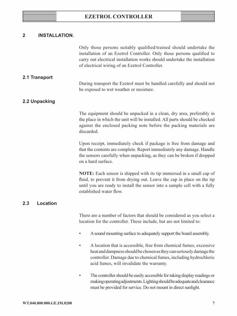
2 InStallatIon.
Only those persons suitably qualified/trained should undertake the installation of an Ezetrol Controller. Only those persons qualified to carry out electrical installation works should undertake the installation of electrical wiring of an Ezetrol Controller.
2.1transportDuring transport the Ezetrol must be handled carefully and should not be exposed to wet weather or moisture.
2.2unpacking
The equipment should be unpacked in a clean, dry area, preferably in the place in which the unit will be installed. All parts should be checked against the enclosed packing note before the packing materials are discarded.
Upon receipt, immediately check if package is free from damage and that the contents are complete. Report immediately any damage. Handle the sensors carefully when unpacking, as they can be broken if dropped on a hard surface.
noTE: Each sensor is shipped with its tip immersed in a small cap of fluid, to prevent it from drying out. Leave the cap in place on the tip until you are ready to install the sensor into a sample cell with a fully established water flow.
2.3 location
There are a number of factors that should be considered as you select a location for the controller. These include, but are not limited to:
• A sound mounting surface to adequately support the board assembly.
• A location that is accessible, free from chemical fumes, excessive heat and dampness should be chosen as they can seriously damage the controller. Damage due to chemical fumes, including hydrochloric acid fumes, will invalidate the warranty.
• The controller should be easily accessible for taking display readings or making operating adjustments. Lighting should be adequate and clearance must be provided for service. Do not mount in direct sunlight.

WT.040.800.000.GE.IM.02088
EzETrol conTrollEr
• High voltage transformers and other energy-emitting electrical devices can affect the delicate sensing circuits of the controller. Locate the board assembly as far away as practical from sources of interference and be sure that it is electrically grounded as specified in the wiring diagrams.
• The Ezetrol is designed to be permanently powered. The main power into the unit should NOT be interlocked with main circulation pumps. The controller has a secondary input (external stop), which is used to isolate the dosing pump outputs. This input is volt-free and must not be powered (or the controller will be damaged, invalidating the warranty).
• The main power feed should be provided from a ‘clean’ 10-amp switched and fused source.
• The position of the nearest drain should also be given consideration, as the standard Ezetrol supply requires a drain that is open to atmosphere to which the sample water to runs. An optional return to filtration, post filer, pipework kit is available.
2.4 Mounting
The Ezetrol should be positioned at an easily read and accessed height. Siemens Water Technologies recommend that the centre of the display is at a height of 1650 mm.
The 9mm pre-drilled holes in each corner of the board should be used to pass an 8mm bolt through. The fixing should be passed through the mounting board and one of the spacers supplied, at each corner.
The board should NOT be fixed directly against the wall, as this would cause damage to the sensor leads that are passed through the back of the board. Spacers are provided to hold the board off the wall by.
2.5 SampleWaterrequirements
Required pressure at flow cell.Minimum 0.25 barMaximum 4.0 bar
A flow of approximately 30 l/hr is required for the accurate operation of the chlorine sensor; the flow regulator automatically limits the amount of water flowing through the cell. A flow in excess of 30 l/hr would be held within the sample water sample pipe work and will eventually pass through

�WT.040.800.000.GE.IM.0208
EzETrol conTrollEr
the flow cell. It is important to use the hose supplied and not to increase the bore of the water supply pipe to prevent undue lag-time between the water entering the sample hose and passing the sensor tips.
Water from the flow cell is normally fed to the drain. It is also possible to return the ‘waste’ water back to a post filter point in the pool water return, at a maximum back pressure of 1.5 bar. A return water installation kit of parts is available.
If the flow cell sample supply water pressure is less than 0.25 bar, a sample water pump may be installed either from the pool or from the circulation system (preferred). The use of a booster pump must include a loop of pipe work with a sample tapping to draw of a proportion of the water to pass through the sample cell. This is so not to put the entire pump pressure directly on the to the flow regulator or to create an artificial lag time.
2.6 SampleSupply
A sample supply should be run to the location of the board assembly from a point on the pre-filter circulation pipework that is common to all circulation pump deliveries and prior to any chemical injection. A ½” (minimum) drain pipe should be run from the ‘tundish’, pre-mounted on the board below the flow cell, to the drain or balance tank that is to be used to handle the sampled water from the flow cell.
For sample runs of 1m to 20m, the use of the supplied LDP40 (6/8mm diameter) flexible hose is preferred from the circulation pump(s) delivery pipework prior to the filter. If possible ensure the sample draw-off point is pre fresh water make-up or Alum/PAC dosing point, as this will detrimentally effect the sample.
The flexible hose should be protected within a 25mm uPVC conduit, suitably supported, and connected to the push-fit adapter on the strainer inlet, outlet and then on the to the flow switch mounted directly under the flow cell.
Failure to use the strainer provided will allow debris such as ‘hair & lint’ to pass into the flow regulator and the flow cell. This will compromise the performance of the Ezetrol and will invalidate the warranty.
For sample runs of 20m upwards, a loop from the circulation pump delivery pipework should be taken to a point below or adjacent to the board mount assembly and returned to the suction side of the circulation pump(s).

WT.040.800.000.GE.IM.0208�0
EzETrol conTrollEr
The sample loop should be run in ½” uPVC pipe, suitably supported throughout its entire length. A ½” tee adjacent to the flow cell should be fitted and a minimal length of 6/8mm hose and connected to the adapter on the strainer inlet, out let and then on the to the flow switch mounted directly under the flow cell. The fittings from the tee to the flow cell are included the ½” uPVC pipe and fitting are to be supplied by others.
Please note that if 50% duty circulation pumps are employed, running only one pump only will reduce the sample rate of flow to the flow cell. Attention should be given to the amount of flow during this period and, if adjusted, the subsequent flow when the second pump flow is restored.
Should the ‘waste’ water be returned to the post filter circulation pipe work remove the ‘tundish’ from the board and the threaded insert, plus the spare threaded insert, used to support an isolation valve.
2.7 Sensorconnection
Remove protective caps from the pH and chlorine sensors. Screw sensors into the flow cell. The chlorine sensor has an integral lead that can not be removed from the sensor. The back nut/thread on the sensor may be screwed into the flow cell without rotating the sensor or ‘knotting’ the lead.
There should be no air bubbles in the tip of the pH sensor, if there are, remove them by gently shaking the sensor (similar to shaking a clinical thermometer).
After start-up, all sensors require a settling-down period of approximately two - four hours. Calibration and other adjustments should only be made after this period and automatic feed control should be switched off. The Ezetrol should not be left in automatic feed mode overnight for 24 hours after first fitting the sensors.
Do not use stabilised chlorine products, as the Ezetrol will not function correctly.
Sensor warranty will be void if the above is not complied with.
2.8 electricalconnections
Only those persons qualified to carry out electrical installation works should undertake the installation of electrical wiring of an Ezetrol Controller.
The electrical supply to the board assembly should be wired via a double pole isolation switch. The supply should be fused at 10 amp max and the location of the fuse clearly identified.

��WT.040.800.000.GE.IM.0208
EzETrol conTrollEr
Please refer to wiring diagrams at the rear of this manual for identification of all the terminals to enable cable connection.
WArnInG: The Ezetrol is designed to be permanently powered. The main power into the unit should NOT be interlocked with main circulation pumps. The controller has a secondary input (external stop), which is used to isolate the dosing pump outputs. This input is volt-free and must not be powered (or the controller will be damaged).
Power requirement: 230V AC, 1PH, 50 Hz.
2.9 Start-up
Upon completion of the entire dosing system being installed, isolate the dosing pumps and external alarms at the local point of isolation.
Open the sample valves and ensure that water is flowing into the cell and out to waste or back into a valved post filter tapping.
Switch on the power isolator at the main panel or distribution board and only then switch on the controller power at the board mount isolator.
The Ezetrol has a 3 minute (adjustable) power up delay timer. The controller will go into to control mode until the count down timer on the main display reaches zero.
The Ezetrol has a 3 minute (adjustable) sample water delay timer. The controller will go into to control mode until the timer runs down.The Ezetrol is now ready to be commissioned by a Siemens Water Technologies Engineer or a Siemens Water Technologies trained engineer.
WT.040.800.000.GE.IM.0208�2
EzETrol conTrollEr
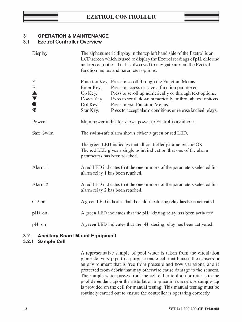
3 operatIon&MaIntenance3.1 ezetrolcontrolleroverview
Display The alphanumeric display in the top left hand side of the Ezetrol is an LCD screen which is used to display the Ezetrol readings of pH, chlorine and redox (optional). It is also used to navigate around the Ezetrol function menus and parameter options.
F Function Key. Press to scroll through the Function Menus. E Enter Key. Press to access or save a function parameter. s Up Key. Press to scroll up numerically or through text options. t Down Key. Press to scroll down numerically or through text options. l Dot Key. Press to exit Function Menus. k Star Key. Press to accept alarm conditions or release latched relays.
Power Main power indicator shows power to Ezetrol is available. Safe Swim The swim-safe alarm shows either a green or red LED. The green LED indicates that all controller parameters are OK. The red LED gives a single point indication that one of the alarm
parameters has been reached.
Alarm 1 A red LED indicates that the one or more of the parameters selected for alarm relay 1 has been reached.
Alarm 2 A red LED indicates that the one or more of the parameters selected for alarm relay 2 has been reached.
Cl2 on A green LED indicates that the chlorine dosing relay has been activated.
pH+ on A green LED indicates that the pH+ dosing relay has been activated.
pH- on A green LED indicates that the pH- dosing relay has been activated.
3.2 ancillaryBoardMountequipment3.2.1 Samplecell
A representative sample of pool water is taken from the circulation pump delivery pipe to a purpose-made cell that houses the sensors in an environment that is free from pressure and flow variations, and is protected from debris that may otherwise cause damage to the sensors. The sample water passes from the cell either to drain or returns to the pool dependant upon the installation application chosen. A sample tap is provided on the cell for manual testing. This manual testing must be routinely carried out to ensure the controller is operating correctly.

�3WT.040.800.000.GE.IM.0208
EzETrol conTrollEr
The sample may have (uncommonly) been taken from a loop of pipe work around the circulation pump or directly from the pool via a booster pump (more uncommonly).
3.2.2 flowSwitch
To ensure that the controller does not continue to dose in the event of no sample water flow to the sample cell and the sensors reading only stagnant water with either a high pH or no chlorine, a reed operated flow switch is fitted. When the flow stops the outputs to the dosing pumps are interrupted and the controller displays a ‘DI’ alarm text. The flow switch should be tested routinely to ensure that the reed switch has not been fouled with such debris and filter sand or hair and operates correctly. The flow switch can be tested simply by shutting off the sample isolation valve.
3.2.3 externalStop
The Ezetrol is designed to be powered up at all times. The Ezetrol incorporates an external stop feature which allows for a volt free input from external ancillary control circuits form such items and the circulation pump starts or a circulation pipe work flow switch. When any of these inputs engages the external stop the outputs to the dosing pumps are interrupted and the controller displays a ‘DII’ alarm text.
3.2.4 Strainer
To protect the probes from any debris passing through the sample cell, a ½” nominal bore strainer is fitted. The strainer must be routinely inspected and cleaned as necessary. When the strainer becomes blocked the flow through the sample cell will be impaired and the lag time for the sample water to pass through the sample hose will start to increase reducing the controllers ability to finely control the pH and chlorine in the pool water.
3.2.5 Isolator
An isolator switch is fitted to isolate the power to the Ezetrol. No one other suitably qualified electrical engineers should open the Ezetrol control. The isolation of the incoming power should be verified prior to carrying our any works within the controller or any external ancillary equipment electrically connected to the Ezetrol.
3.3.0Sensors3.3.1Sensorcleaning
The intervals between sensor cleaning will be established on site over a period of time. We do not advise that the sensors be routinely cleaned without proper cause, as this will lead to a shortening of the sensor life.
WT.040.800.000.GE.IM.0208�4
EzETrol conTrollEr
Clean only when the controller accuracy begins to fall and the interval between calibration begins to decrease.
The Ezetrol has a grit based sensor scouring action. The ‘swirling’ grit in the cell gently removes debris build up. Over a period of time the debris deposits may overtake the cleaning action and sensors will require cleaning. The grit will also lose its sharp edges and erode away requiring topping up.
To clean the probes:
1 Shut the sample cell valve(s). The grit in the cell will stop moving around and the flow can be seen not to overflow the rear outlet hole.
2 Disconnect the pH sensor lead by unscrewing the plug from the top of the probe. The pH sensor may now be unscrewed from the flow cell.
3 The chlorine sensor can not be disconnected from the lead. The back nut unscrews from the flow cell without rotating the sensor or ‘knotting’ the lead. The chlorine sensor may be lifted out of the sample cell.
4 Remove the sensors from the sample cell and rinse in the Probe Cleaner supplied. Read the instructions on the label carefully as this product is acid based. Rinse both probes well in fresh water and ‘shake-down’ the pH probe. Make sure you ‘shake-down’ the pH probe on every occasion.
5 Replace the sensors in the sample cell by reversing the operation described above. And reopen the sample cell valve(s). Check for correct flow by taking a note of the ‘swirling’ grit in the sample cell.
6 Rinsing the sensors in the acid solution will ‘shock’ them. The display readings on the Ezetrol will take some time to settle after re-fitting. Before calibration, carefully monitor the Ezetrol display and the pool readings. Once the display/sensors have settled, calibrate the display to the manual test kit readings.
3.3.2probereplacement
The sensors for the Ezetrol are supplied with an 18 month warranty. The life of the probe is dependant upon the demands placed upon it from bather pollution and, therefore the frequency of cleaning. We suggest you assess your probe efficiency between 2 and 3 years.
�5WT.040.800.000.GE.IM.0208
EzETrol conTrollEr
3.3.3 probecare
Should the sample cell be drained or the probes removed from the sample cell, they must be kept in the protective cap supplied, which should contain a little water. If the probes are left dry for more than 1 hour the liquid junction will dry out and the probe will ‘die’.
3.4 Seasonaloperation
If your pool is closed during the winter months, or will not be circulating at all times in freezing conditions, the probes should be removed from the flow cell, replaced in the protective cap which should contain a little water, and taken to a warmer environment.
It is generally recommended that any electrical & electronic equipment not being used during winter months is removed to a warm dry atmosphere.
3.5 ezetroloperation3.5.1 accesscode
Although all of the functions may be accessed and read at any time, adjustment cannot be made unless the appropriate access code is first entered. There is one access code, which may have been enabled during the commissioning procedure.
To access the controller.
1 Press the s key repeatedly until the ‘code ??????’ is displayed.
2 Press the e key to enter the new value.
3 Press the s key until the desired code is displayed.
4 Press the e key to enter the displayed value.
5 Press the l key to return to the normal display.
The controller now has the access code selected, the correct code input, entered and the controller ‘open’ for access.
After one hour without pressing a key the value in the display menu is set to 000 and the Ezetrol is access protected.
If the access code has not been enabled during commissioning the controller will be free to access at all times.

WT.040.800.000.GE.IM.0208��
EzETrol conTrollEr
3.5.2chlorinesetpointadjustment
To adjust the chlorine set point;
1 When in normal operating display (with the actual chlorine and pH readings on the screen) press the s key until the text on the screen reads ‘setpoint cl2’.
2 Press the e key to access the chlorine set point parameter.
3 Press the s or t keys until the desired set point is displayed.
4 Press the e key to enter and save the new value.
5 Press the l key to return to the normal operating display with the new set point.
3.5.3pHsetpointadjustment
To adjust the pH set point;
1 When in normal operating display (with the actual chlorine and pH readings on the screen) press the s key until the text on the screen reads ‘setpoint pH’.
2 Press the e key to access the pH set point parameter.
3 Press the s or t keys until the desired set point is displayed.
4 Press the e key to enter and save the new value.
5 Press the l key to return to the normal operating display with the new set point.
3.5.4 chlorinecalibration.
From normal operating display (with the actual chlorine and pH readings on the screen).
1 Press the f key until the text on the screen reads 'cAlIBrATIon'.
2 Press the s key until the display reads 'cl2 DPD'. Carry out a manual DPD No.1 Free Chlorine test.
��WT.040.800.000.GE.IM.0208
EzETrol conTrollEr
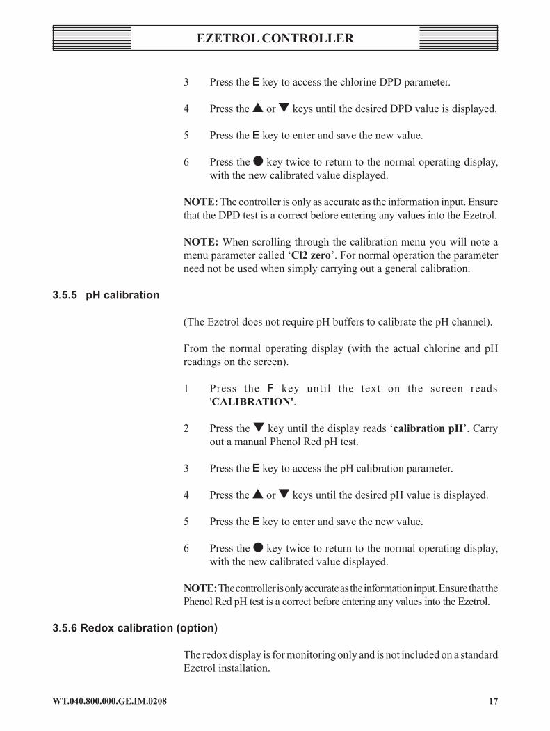
3 Press the e key to access the chlorine DPD parameter.
4 Press the s or t keys until the desired DPD value is displayed.
5 Press the e key to enter and save the new value.
6 Press the l key twice to return to the normal operating display, with the new calibrated value displayed.
noTE: The controller is only as accurate as the information input. Ensure that the DPD test is a correct before entering any values into the Ezetrol.
noTE: When scrolling through the calibration menu you will note a menu parameter called ‘cl2 zero’. For normal operation the parameter need not be used when simply carrying out a general calibration.
3.5.5 pHcalibration
(The Ezetrol does not require pH buffers to calibrate the pH channel).
From the normal operating display (with the actual chlorine and pH readings on the screen).
1 Press the f key until the text on the screen reads 'cAlIBrATIon'.
2 Press the t key until the display reads ‘calibration pH’. Carry out a manual Phenol Red pH test.
3 Press the e key to access the pH calibration parameter.
4 Press the s or t keys until the desired pH value is displayed.
5 Press the e key to enter and save the new value.
6 Press the l key twice to return to the normal operating display, with the new calibrated value displayed.
noTE: The controller is only accurate as the information input. Ensure that the Phenol Red pH test is a correct before entering any values into the Ezetrol.
3.5.6redoxcalibration(option)
The redox display is for monitoring only and is not included on a standard Ezetrol installation.

WT.040.800.000.GE.IM.0208�8
EzETrol conTrollEr
From normal operating display (with the actual chlorine and pH readings on the screen).
1 Press the l key until the text on the screen reads 'cAlIBrATIon'.
2 Press the t key until the display reads ‘calibration mV’. Insert the mV in a known redox buffer solution.
3 Press the e key to access the redox calibration parameter.
4 Press the s or t keys until the desired redox value is displayed.
5 Press the e key to enter and save the new value.
6 Press the l key twice to return to the normal operating display, with the new calibrated value displayed.
3.5.7pumpoperation
The dosing pumps may be run either automatically, by the Ezetrol, or manually. In manual mode the dosing pumps may be either switched on or off. When in the ‘on’ mode a timer is engaged to switch the pumps off after a predetermined, user defined, period. The run time maybe set between 0.1hours (6 minutes) and 10.0 hours.
To put the Ezetrol into automatic or manual mode:
1 When in normal operating display (with the actual chlorine and pH readings on the screen) press the s key until the text on the screen reads ‘Mode’.
2 Press the e key to access the pump control mode parameter. Press the s or t keys scrolling between ‘manual’ and ‘automatic’.
3 Press the e key to enter and save the new value.
4 Once ‘manual’ has been selected the Ezetrol sets the manual mode to ‘manual-off’ for both the pH and chlorine channels. To select which channel (pH or chlorine or both) you wish to run the dosing pump manually for the predetermined period of time press the s or t keys until pump ‘cl2’ or ‘pump pH’ is reached. With the desired pump displayed press the e key and use the s or t keys to scroll between ‘off’ and ‘on’ press the e key to enter and save the desired pump operation mode.
��WT.040.800.000.GE.IM.0208
EzETrol conTrollEr
5 The normal display will show either a circle with a small tail indicating automatic or a hammer symbol for manual control.
6 When the controller is changed from manual to automatic mode the feed delay timer is enabled and the controller will not feed until the count down timer on the display screen reaches zero.
3.5.8overfeedfailsafealarm
The Ezetrol is programmed to feed chemicals, when called for, only for a limited preset period. This protection minimises any further complications in the event of a blocked injector, empty day tank, split hose, failed flow-switch or failed probe. An Overfeed Failsafe condition is indicated by ‘overfeed’ being shown in the alphanumeric display. Before accepting and cancelling the alarm, determine the reason for the ‘overfeed’, rectify the fault and only then press the k to restore normal dosing.

WT.040.800.000.GE.IM.020820
EzETrol conTrollEr
4 coMMISSIonIng
The commissioning of this controller must only be undertaken by those engineers trained by Siemens Water Technologies. Commissioning by any other persons will invalidate the controller warranty.
4.1 commissioningprocedure
The contents of the Ezetrol commissioning manual describes in detail the operation and use of each of the controller’s functions. To commission the controller, the requirements of each individual pool should be assessed and the relevant function of the controller adjusted accordingly, in line with the instructions. As all pools are different and require different settings, no values are given for adjustment and any pre-set value that is adjusted should be recorded. There is a “Notes” section in the back of the manual for this purpose.
1 Check the electrical connections and power to the controller.
2 Check that chemical tanks/CO2 cylinders are full and ready for operation.
3 Set the sample flow and insert the probes.
4 Set the controller parameters to the desired values, specific to the pool’s requirements.
5 Calibrate the controller.
6 Check and commission the ancillary equipment in line with relevant instructions found elsewhere.
WArnInG: Damage due to chemical fumes, including hydrochloric acid fumes, will invalidate the warranty.
4.2flowcellSet-up
Upon completion of the entire dosing system being installed, isolate the dosing pumps and external alarms at the local point of isolation.
Open the sample valves and ensure that water is flowing into the cell and out to waste or back into a valved post filter tapping. Once the cell has filled to the outlet hole half way up the rear sample cell shut off the inlet and outlet (if applicable) valves.
One cap full of probe cleaning granules should be poured into the sample cell, whilst the flow is isolated, through one of the threaded holes in the top of the cell.
2�WT.040.800.000.GE.IM.0208
EzETrol conTrollEr
Remove the protective caps from the pH, chlorine and (optional) redox sensors. Screw sensors into the flow cell. The chlorine sensor has an integral lead that can not be removed from the sensor. The back nut thread on the sensor may be screwed into the flow cell without rotating the sensor or ‘knotting’ the lead.
There should be no air bubbles in the tip of the pH sensor. If there are remove them by gently shaking the sensor (similar to shaking a clinical thermometer).
There should be no air bubbles in the tip of the (optional) redox sensor. If there are remove them by gently shaking the sensor (similar to shaking a clinical thermometer).
Switch on the power isolator at the main panel or distribution board and only then switch on the controller power at the board mount isolator.
The Ezetrol has a power up pre-set timer delay. After the unit is switched on a 3 minute delay timer prevents the controller operating in automatic control mode.
The Ezetrol has sample water pre-set timer delay. After the flow switch engages a 3 minute delay timer prevents the controller operating in automatic control mode.
After start-up, all sensors require a settling-down period of approximately two - four hours. Calibration and other adjustments should only be made after this period and automatic feed control should be switched off. The Ezetrol should not be left in automatic feed mode overnight for 24 hours after first fitting the sensors.
To check the operation of the flow switch in the cell, shut off the isolation valve on the board (or on the main circulation pipe tapping).
Immediately that the flow is isolated the controller should display DI in the top right hand corner of the LCD screen.
In this event the output relays to the dosing pumps or feeders should also be isolated.
Once the operation of the flow switch has been checked, the flow should be re-established.
To check the operation of the external stop the circulation pumps, or any other external device fitted to isolate the dosing pump outputs, should be shut down.
Immediately that the external stop is isolated the controller should display DII in the top right hand corner of the LCD screen.

WT.040.800.000.GE.IM.020822
EzETrol conTrollEr
In this event the output relays to the dosing pumps or feeders should also be isolated.
Once the operation of the ‘external stop’ has been checked, the circulation pumps, or any other external device fitted to isolate the dosing pump outputs, should be restarted.
4.3 adjustmentandcalibration
All adjustments and calibration to the chlorine, pH and (optional) redox channels are carried out using the keys on the face of the controller.
4.4 Menunavigation
The controller is divided up into a different Function Menus for various parameter settings.
Navigation of the Function menus is carried out by initially pressing the f key and repeating until the desired menu is reached. The s & t keys are used the scroll through the selected menu to the desired parameter.
The e key is pressed to make a change to the desired parameter and the s & t keys are used to scroll through the numerical values or the parameter text options.
The e key is pressed to confirm the new value.
The l key is used to exit the chosen Function menu. The navigation of the Function menus is continued by pressing the f key and repeating until the desired Function menu is reached.
The l key may be pressed when at the menu function heading to return to the normal display of Chlorine, pH and (optional) redox.
Whilst in the standard display the s key may be pressed and repeated to scroll though the display menu.
The Function menus are broken down as described below.• Calibration• Chlorine Parameters• pH Parameters• Alarm• Alarm Relay I• Alarm Relay II• Set Up• Auto Tune• Diagnostics

23WT.040.800.000.GE.IM.0208
EzETrol conTrollEr
4.5 accesscode
Although all of the functions may be accessed and read at any time, adjustment cannot be made unless the appropriate access code is first entered. There is one access code, which is pre-set with a value of 000 and therefore is not enabled.
We recommend that an access code of 011 is set and enabled.
To set a new access code;
1 Press the f key repeatedly until the set up function menu is displayed.
2 Press the s key repeatedly until the ‘code definition’ parameter is displayed.
3 Press the e key.
4 Press the s key until the desired code is displayed. We advise that code 011 be selected.
5 Press the e key to enter the new value.
6 Press the l key to return to the Function menu heading.
7 Press the l key to return to the normal display.
To access the controller once a new code has been set.
1 Press the s key repeatedly until the ‘code ??????’ is displayed.
2 Press the e Key to enter the new value.
3 Press the s key until the desired code is displayed.
4 Press the e Key to enter the displayed value.
5 Press the l key to return to the normal display.
The controller now has a new access code selected, the correct code input and the controller ‘open’ for access.
After one hour without pressing a key the value in the display menu is set to 000 and the Ezetrol is access protected.

WT.040.800.000.GE.IM.020824
EzETrol conTrollEr
4.6 overfeedprotection
The Ezetrol is supplied with a default overfeed protection value of 0.1hrs (6mins). The desired overfeed limit must be assessed during commissioning and input.
The overfeed limit should be set so as to provide adequate time for the action directed by the controller to pass through the pool circulation system and return to the controller flow cell, without undue time being allowed for which may cause complications in the event of a blocked injector, empty day tank, split hose, failed flow-switch or failed probe.
Each and every pool will require a different setting dependant upon the time taken for the controller enter the proportional band from a low chlorine or high pH level.
4.6.1 toadjusttheoverfeedprotectiontime.
From normal operating display (with the actual chlorine and pH readings on the screen).
1 Press the f key until the text on the screen reads ‘SET UP’.
2 Press the t key until the display reads ‘overfeed delay’.
3 Press the e key to access overfeed delay parameter.
4 Press the s or t keys until the overfeed delay value is displayed. The range is 0.1 to 10 hours in 0.1hour increments.
5 Press the e key to enter and save the new value.
6 Press the l key twice to return to the normal operating display.
4.7 proportionalcontrolofon/offSolenoid&Motordrivendosingpumps.
The pump is switched on, within the variable duty cycle (or proportional time base), for a calculated switch-on (relay contact) time. The duty cycle depends mainly on the reaction time (process time) of the particular swimming pool. The default is set at 60 seconds.
Example: Duty Cycle (Tp) = 100 seconds. Output Value (Y out) = 30% Switch-on Time = 30 seconds. Switch-off Time = 70 seconds.

25WT.040.800.000.GE.IM.0208
EzETrol conTrollEr
OnOff
The following controller parameters can be set with the controller:
Xp (%) Proportional factor 1 - 1000 %Tn (sec.) Integral action time 0 - 100 minutes.Tp (sec.) Duty cycle 10 - 180 seconds
The dynamic behaviour of the controller is adjustable via parameters Xp and Tn. This permits the adaptation of the controller to different lag times of the pool circulation system.
noTE: With the Integral Action Time (Tn) set to zero (0) minutes the chlorine controller will work as a proportional only controller.
4.7.1 toselectthedosingpumptype
From normal operating display (with the actual chlorine and pH readings on the screen).
1 Press the f key until the text on the screen reads ‘cl2 Menu’ or ‘pH Menu’.
2 Press the t key until the display reads ‘control output’.
3 Press the e key to access pulse selection parameter.
4 Press the s or t keys until the required choice is displayed. The choices are ‘pump’ or ‘pulse pump’. Your choice will be
dependent upon the type of pump selected.
5 Press the e key to enter and save the new value.
6 Press the l key twice to return to the normal operating display.
4.8 Solenoidpulsepumps
Solenoid pulse pumps are controlled to regulate the feed rate between 0 to 100 or 120 pulses per minute in proportion to the measured value, the set point and the control parameters.
For both pulse pump options (100 or 120 pulses/min) the ‘on-time’ of the pump is 0.25 seconds and the ‘off-time’ is set between 0.25 and 60 seconds depending on the desired feed rate.
WT.040.800.000.GE.IM.02082�
EzETrol conTrollEr
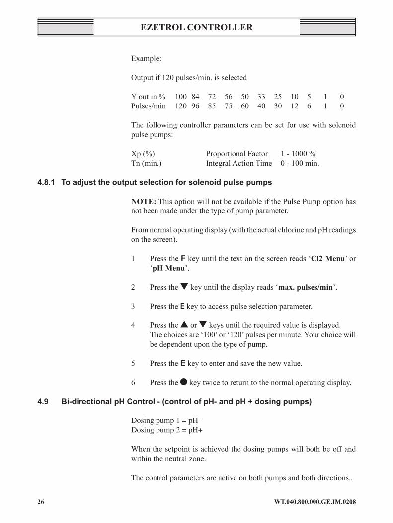
Example:
Output if 120 pulses/min. is selected
Y out in % 100 84 72 56 50 33 25 10 5 1 0Pulses/min 120 96 85 75 60 40 30 12 6 1 0
The following controller parameters can be set for use with solenoid pulse pumps:
Xp (%) Proportional Factor 1 - 1000 %Tn (min.) Integral Action Time 0 - 100 min.
4.8.1 toadjusttheoutputselectionforsolenoidpulsepumps
noTE: This option will not be available if the Pulse Pump option has not been made under the type of pump parameter.
From normal operating display (with the actual chlorine and pH readings on the screen).
1 Press the f key until the text on the screen reads ‘cl2 Menu’ or ‘pH Menu’.
2 Press the t key until the display reads ‘max. pulses/min’.
3 Press the E key to access pulse selection parameter.
4 Press the s or t keys until the required value is displayed. The choices are ‘100’ or ‘120’ pulses per minute. Your choice will
be dependent upon the type of pump.
5 Press the e key to enter and save the new value.
6 Press the l key twice to return to the normal operating display.
4.9 Bi-directionalpHcontrol-(controlofpH-andpH+dosingpumps)
Dosing pump 1 = pH-Dosing pump 2 = pH+
When the setpoint is achieved the dosing pumps will both be off and within the neutral zone.
The control parameters are active on both pumps and both directions..
2�WT.040.800.000.GE.IM.0208
EzETrol conTrollEr
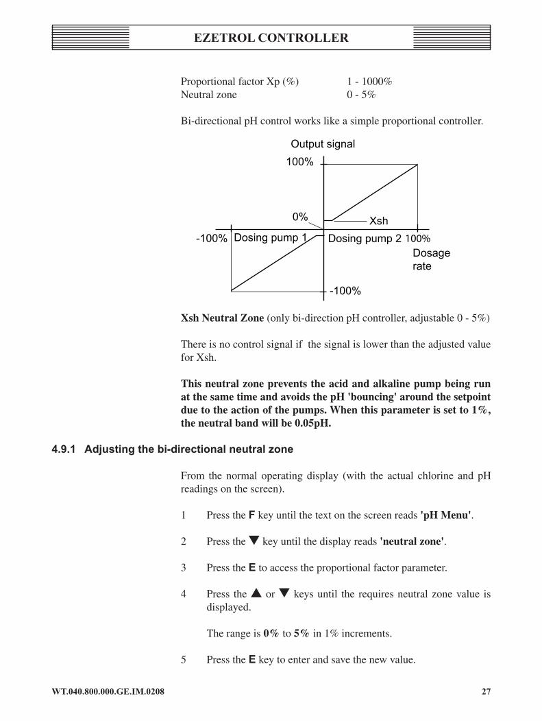
Proportional factor Xp (%) 1 - 1000%Neutral zone 0 - 5%
Bi-directional pH control works like a simple proportional controller.
Xsh Neutral Zone (only bi-direction pH controller, adjustable 0 - 5%)
There is no control signal if the signal is lower than the adjusted value for Xsh.
This neutral zone prevents the acid and alkaline pump being run at the same time and avoids the pH 'bouncing' around the setpoint due to the action of the pumps. When this parameter is set to 1%, the neutral band will be 0.05pH.
4.9.1 adjustingthebi-directionalneutralzone
From the normal operating display (with the actual chlorine and pH readings on the screen).
1 Press the f key until the text on the screen reads 'pH Menu'.
2 Press the t key until the display reads 'neutral zone'.
3 Press the e to access the proportional factor parameter.
4 Press the s or t keys until the requires neutral zone value is displayed.
The range is 0% to 5% in 1% increments.
5 Press the e key to enter and save the new value.
Output signal100%
-100%
-100%
0%
Dosing pump 1 Dosing pump 2Dosagerate
Xsh

WT.040.800.000.GE.IM.020828
EzETrol conTrollEr
6 Press the l key twice to return to the normal operating display.
4.10 proportionalfactor(Xp)
The proportional factor (Xp) increases or decreases the rate of the dosing pump output in proportion to the deviation between the set point and the actual reading.
In order to provide the most precise output control in response to any deviation from set point the Ezetrol takes into account the set point, actual value and proportional factor to control the dosing pump. The pump output is then calculated as a percentage of the run time in seconds.
For example the percentage pump output is calculated from the deviation of the actual; reading from the set point multiplied by the proportional factor, or:
Deviation % x Xp Factor = Pump Output %
Where:
Deviation mg/l• Deviation % = x 100% Full Scale Control
• Xp Factor = (1/Xp) X 100%
• Full Scale control = Set Point X 2
For a pool with:
Set Point (mg/l) 1.50 Actual reading (mg/l) 1.40 Xp 10%
The pump output would be calculated as:
Deviation = 1.50 – 1.40 = 0.10mg/l
0.1 mg/lDeviation % = x 100% = 3% 3.00 mg/l
Proprtional Control (Xp) factor = (1/10) x 100 = 10.00

2�WT.040.800.000.GE.IM.0208
EzETrol conTrollEr
Full Scale Control 1.5mg/l x 2 = 3.00
Therefore pump output % = 3% x 10 = 30%
For a 60 seconds time base 30% = 18 seconds On and 42 seconds OffEffect:
The smaller the proportional factor (Xp), input as a percentage, the faster the pump output increases as the actual value deviates from the set point. The larger the proportional factor (Xp), input as a percentage, the slower the pump output increases as the actual value deviates from the set point.
The proportional factor (Xp) can be changed within the range of 1% to 1000%, the default setting is 10%. It is not recommended that this value is set above 15% or below 10% without first consulting the Technical Help Desk.
4.10.1adjustingtheproportionalfactor(Xp)
From normal operating display (with the actual chlorine and pH readings on the screen).
1 Press the f key until the text on the screen reads ‘cl2 Menu’ or ‘pH Menu’ .
2 Press the t key until the display reads ‘proport. Factor’.
3 Press the e key to access proportional factor parameter.
4 Press the s or t keys until the required proportional factor value is displayed. The range is 1% to 1000% in 1% increments.
5 Press the e key to enter and save the new value.
6 Press the l key twice to return to the normal operating display.
4.11 Integralactiontime(tn)
This feature is only available on the chlorine channel.
With the Integral Action Time (Tn) the controller can continuously increase the dosing capacity of the pump with constant control deviation until the set point is reached. The longer the selection of Integral Action Time (Tn) in minutes, the longer the period until the metering pump increases its dosing capacity.

WT.040.800.000.GE.IM.020830
EzETrol conTrollEr
The increase of the dosing capacity depends on the control deviation and on Proportional (Xp) and Integral Action Time (Tn) values.
The Integral Action Time (Tn) parameter is adjustable 0 - 100 minuets when the Integral Action Time (Tn) is set a 0-minutes the integral component is switched off and only the proportional parameter is active.
Example: Control deviation Xd* = 20 % Proportional factor Xp = 100 % Integral action time Tn = 5 min
The controller starts with 20% dosing capacity (P-component =Xp · Xd). If the control deviation is not reduced, then the controller will continuously increase the dosing capacity by 20% every five minutes.
Therefore the maximum dosing capacity of 100 % is achieved within 20 minutes.
*The deviation is calculated as:
setpoint - actual reading Xd = x 100 % full scale range
noTE: The Ezetrol has a fixed full-scale range of 10 mg/l.
Dosing Capacity
100%
80%
60%
40%
20%
I-component
P-component
Minutes5 5 10 15 20
Tn Tx
4.11.1adjustingtheintegralactiontime(tn)
From normal operating display (with the actual chlorine and pH readings on the screen).
1 Press the f key until the text on the screen reads ‘cl2 Menu’.

31WT.040.800.000.GE.IM.0208
EzETrol conTrollEr
2 Pressthetkeyuntilthedisplayreads‘integr.act.Time’.
3 PresstheEkeytoaccessintegralactiontimeparameter.
4 Pressthesortkeysuntil therequiredIntegralActionTimevalueisdisplayed.
Therangeis0(off)to200minutesin1minuteincrements.
5 PresstheEkeytoenterandsavethenewvalue.
6 Pressthelkeytwicetoreturntothenormaloperatingdisplay.

WT.040.800.000.GE.IM.020832
EzETrol conTrollEr
5 MenuovervIeWS5.1 displayMenu
Default values are shown in bold type.
display range description
1.50mg/lxxx..7.50pH800mv
Measuredvalues,units(Basicdisplay)(xxx)countdowntimefor"feeddelay"inseconds;default180s(**)symbol"automatic/manual"-mode
pumpcl2 ON, OFFManualoperationofdosingpumpcl2(unless automatic is selected)
setpointcl2 0.15 - 9.99 mg/l(1.50mg/l) chlorineSetpoint
pumppH ON, OFFManualoperationofdosingpumppHcorrection(unless automatic is selected)
setpointpH7.50pH 4.00 - 9.00 pH(7.50pH) pHSetpoint
Man.runtime 0.1....10h0.1h(6minutes)
runtimeforthepumpswheninmanualmode
Mode automaticmanual
operationmodeThe selected mode is displayed with symbols(circle = auto., hammer = manual)
Menu conciseextended
MenulengthSelection of the menu length;- Concise menu: Display and calibration menus only- Extended menu: All menus are displayed
code 000999
codeEntering of the code-numberIf the access code value displayed is not the same as in the value input in the 'code-definition' parameter, no changes to the Ezetrol settings may be made.."code???" appears in the display if access is attempted without correct code number.The code menu disappears if the 'code-definition' value is set to 000.

33WT.040.800.000.GE.IM.0208
EzETrol conTrollEr
5.2 calibrationfunctionMenu
Calibration adjustments are made in this menu.Default values are shown in bold type.
noTE: The control output is frozen during calibration. The mA output is frozen, if the hold function in the Set-Up Menu is active.
display range description
cl2zero 0.00 mg/lchlorinezerocalibrationPress the e key to calibrate to 0.00 mg/l
cl2dpd 0.00 - 9.99mg/l
chlorinedpdcalibrationEnter the value measured by DPD with the s and t keys.Press the e key to calibrate to this value
calibrationpH 7.00 - 8.00pH
pHcalibrationPress the E key to enter the calibration function.If necessary press the s or t key to adjust to ±1.0 pH unit.
calibrationmv 834 mV
redoxcalibrationEnter the value of the buffer solution with the s and t keys.Press the E key to calibrate to this value
samp.watertemp.-10°C+50°C(30°c)
temperatureforthecompensationPress the s and t keys to enter the sample water temperature. The temperature is used for the automatic pH correction.

WT.040.800.000.GE.IM.020834
EzETrol conTrollEr
5.3 cl2parameterfunctionMenu
Chlorine channel Adjustments are made in this menu.Default values are shown in bold type.
display range description
controloutput pumpsol.pump
Selectionofthecontroloutputforchlorinefeed:pump = for on/off solenoid and motor driven dosing pumppulse. pump: = for solenoid dosing pumpsThe following menu options depend on the selection in this menu)
proport.factor1%
100%(10%)
control-gain(Xp)Proportional factor of the Cl2 controller1% means factor 100 (high gain)10% means factor 10 (medium gain - default value)100% means factor 1 (low gain)
integr.acttime
0.0 - 100.0 min(20.0min)
Integral-actiontime(tn)Integral action time of the Cl2 controllerIf 0.0 min is entered, the integral component is switched off, the controller works as a pure P-controller.
Max.pulses/min
100120
MaximumpulsesperminuteAccording to the design of the pH correction solenoid pump.NOTE: Only if pulse. pump is selected.
dutycycle 10-180sec.(60sec)
adjustmentoftheoperatingcycle(tp)This adjustment is only possible with normal motor pumps.

35WT.040.800.000.GE.IM.0208
EzETrol conTrollEr
5.4 pHparaMeterfunctionmenu
pH channel adjustments are made in this menu.Default values are shown in bold type.
display values description
controloutput
pumppump bi-directpulse. pump
pulse. pump bi-direct
SelectionofthecontroloutputforthepHcorrectionpump: for on/off solenoid and motor driven dosing pumppump bi-direct: for 2 motor dosing pumps (pH+ and pH-)pulse.pump: for solenoid dosing pumppulse. pump bi-dir : for 2 solenoid dosing pumps (pH+ and pH-)(Some function menu options may not be available depending upon the selection made in this menu.)
proport.factor1%
100%(10%)
control-gain(xp)Proportional factor of the pH controller1% means factor 100 (high gain)10% means factor 10 (medium gain - default value)100% means factor 1 (low gain)
max.pulses/min
100120
MaximumpulsesperminuteAccording to the design of the solenoid pumpNOTE: only if pulse. pump is selected
dutycycle10s
180s(60s)
Adjustment of the operating cycle TpThis adjustment is only possible with normal motor pumps
neutralzone 0 - 5% 1%
adjustmentoftheneutralzoneXsh between acid and alkaline dosing; (1% = 0.05 pH) Note: This menu option is only displayed when bi-directional dosing is enabled
controldirect. pH+ corr.pH-corr.
controldirectionoftheacidoralkalinedosing.pH+ : Only alkaline dosing pump is connected. The alkaline increases the pH value.pH- : Only acid dosing pump is connected. The acid reduces the pH value. NOTE: This menu option is not displayed when bi-directional dosing is enabled.
.

WT.040.800.000.GE.IM.02083�
EzETrol conTrollEr
5.5 alarmfunctionMenu
Alarm limits adjustment are made in this menu. Default values are shown in bold type.
display range description
cl2max Full range5.00mg/l Maximumlimitforchlorinelevel
cl2min Full range5.00mg/l Minimumlimitforchlorine
pHmax Full Range 8.00pH MaximumlimitforpH
pHmin fullrange7.00pH MinimumlimitforpH
redoxmax Full Range900mv Maximumlimitforredox(option)
redoxmin Full Range 600mv Minimumlimitforredox(option)
noTE: This menu only defines the operator defined alarm limits.
The alarm output relays may not have been configured to operate for certain user-defined alarm conditions.
The ‘swim-safe’ alarm indicates a general alarm condition based upon the above alarm limits.
3�WT.040.800.000.GE.IM.0208
EzETrol conTrollEr
5.6 alarm-relay1functionMenu
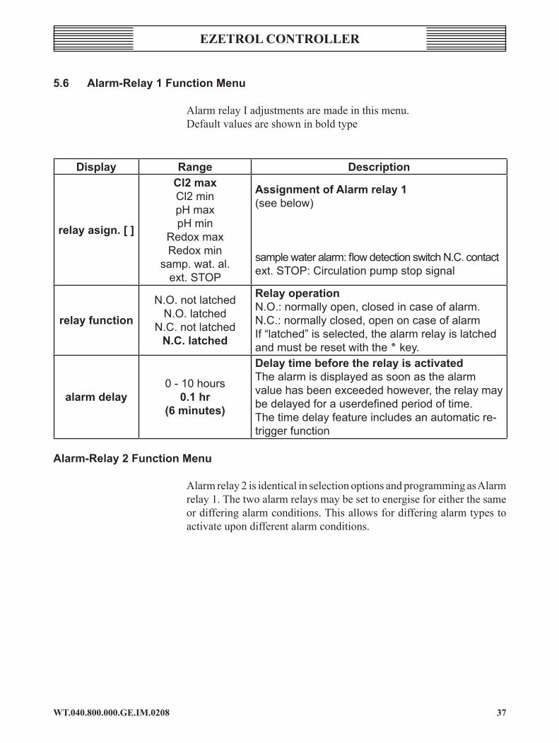
Alarm relay I adjustments are made in this menu.Default values are shown in bold type
display range description
relayasign.[]
cl2maxCl2 minpH maxpH min
Redox maxRedox min
samp. wat. al. ext. STOP
assignmentofalarmrelay1(see below)
sample water alarm: flow detection switch N.C. contactext. STOP: Circulation pump stop signal
relayfunction
N.O. not latchedN.O. latched
N.C. not latchedn.c.latched
relayoperationN.O.: normally open, closed in case of alarm.N.C.: normally closed, open on case of alarmIf “latched” is selected, the alarm relay is latched and must be reset with the ٭ key.
alarmdelay0 - 10 hours
0.1hr(6minutes)
delaytimebeforetherelayisactivatedThe alarm is displayed as soon as the alarm value has been exceeded however, the relay may be delayed for a userdefined period of time.The time delay feature includes an automatic re-trigger function
alarm-relay2functionMenu
Alarm relay 2 is identical in selection options and programming as Alarm relay 1. The two alarm relays may be set to energise for either the same or differing alarm conditions. This allows for differing alarm types to activate upon different alarm conditions.

WT.040.800.000.GE.IM.020838
EzETrol conTrollEr
5.6.1 Settingarelayassignment relayasign.[]inabovemenu
display action remarkrelayasign.[]cl2max press keye openthemenu
relayasign.>[]cl2max scroll up or down
Scroll through the lis of options with the s and t keys until the desired parameter is displayed,'>' indicates the current parameter option
relayasign.>[3]cl2max press keye A '3' will appear confirming the selection
To deselect press key'e'again
relayasign.>[]pHmax s & t keys Select the other alarm parameters
[]ext.Stop>savee t keys
To store the selected alarm parameters scroll the '>' to the lower line by pressing the t key and save the changes with the 'e' key

3�WT.040.800.000.GE.IM.0208
EzETrol conTrollEr
5.7 SetupfunctionMenu
General Ezetrol option adjustments are made in this menu.Default values are shown in bold type
display values description
feeddelay0 - 10.0 minutes
3.0minutes
When activated a count down, shown seconds, will be shown in the main display if:• Manual to automatic control mode is selected.• Power on (start up).• Digital IN 1 or 2 (flow switch or external stop input) is detected
overfeeddelay0 - 10 hours
0.1hr(6minutes)
Isolates the dosing output relays if permanent 100% dosing ON time exceeds the input value.Note: this feature is only enabled in automatic dosing mode.
samp.waterdelay
0 - 10 min(0min)
Flow switch alarm delay time.The flow switch alarm delay time allows for dosing to continue even when flow has stopped for the period of time selected.
holdfunction onOFF
If the hold function ON is selected, the mA output is frozen during calibration
languageGerman,english,
French, Italian, Spanish,Portuguese,
GreekAvailable languages of the menu tree
maoutput onOFF
maoutputIf selected, it must be connected (R≥1 kOhm).Otherwise the error *mA 1/2/3* is displayed
masignal 4...20ma0...20 mA mA output signal selected
displayselect cl2,pH,redox Selection of the measured values to be displayed.Selection according to the version
rS485addr.cl2 0...31,(00) Address in the RS485 bus for the Cl2 value
rS485addr.pH 0...31,(01) Address in the RS485 bus for the pH value
rS485addr.red. 0...31,(02) Address in the RS485 bus for the Redox value
codedefinition
000999
A user-defined access code is available. Once input the correct code must be input before any Ezetrol modifications may be made.
After one hour without pressing a key the value in the code menu is set to 000 and the Ezetrol is protected.

WT.040.800.000.GE.IM.020840
EzETrol conTrollEr
display values description
brightness 0 - 100%(30%)
Adjustment of the display contrastThe backlight of the display can be adjusted in the range from 0 to 100%
NOTE: In a bus system, no addresses can be duplicated.
5.8 autotuneMenu
In this menu path the parameter Xp and Tn can be calculated by the manual input of the lag time (Tu) and rise time (Ts) of the chlorine control loop. The Ezetrol includes a program that can automatically determine the control loop time. (See below 'auto tune' start).
NOTE: The parameters forthe pH control remain unchanged.
Default values are shown in bold type.
display values remark
lagtimetu 1 - 3600 sec(3600 sec = 60 min.)
processtime(tu)ofthecontrolloop.Every time the Tu value is changed and stored with the E key, then the parameters proportional (Xp) and integral action time (Tn) are newly calculated. For the calculation the actual value of the rise time (Ts) is used. After a finished auto tune process the determined value of the lag time is shown in this menu.
risetimets 0.1 - 480.0 min(480 min = 8 hrs)
raisetime(ts)ofthecontrolloopEvery time the Ts value is changed and stored with the E key, the parameters Xp and tn are newly calculated. For the calculation the actual value of the lag time tu is used. After a finished auto tune process the determined value of the rise time is shown in this menu.
autotune start
autotunestartMenu to start the adaption (auto tune). This menu will end only after a complete auto tuning or an adaption break. After a successful adaption the parameter Xp, Tn, Tu and Ts will be updated.After the auto tuning the controller runs in the selected mode. If you start the adaption from the automatic mode, the unit will change to the automatic mode again.

4�WT.040.800.000.GE.IM.0208
EzETrol conTrollEr
5.9 diagnosticMenu
Internal measurements and controller status are displayed in this menu.
display remark
cellcurrentµadisplaystheactualcurrent,inµa,ofthechlorineprobeTypical values: 0.00 mg/l chlorine = 0 µA (approx) 2.00 mg/l chlorine = 15 µA (approx)
cellcurrentµa/mg/l
displaystheactualcurrent,inµa/.mg/l,ofthechlorineprobeTypical value: 6-8 µA/ mg/l (sensitivity per mg/l)
pHelectrodemvdisplaysthepHactualprobe/voltageTypical values: 0 mV = pH7 -56 mV = pH8
mvelectrode+800mv displaysactualredoxprobevoltage
rel:123456st:000000
StatesoftherelaysWhen the relay is activated : '1' is displayed.Assignment of the relays (referring to the wiring diagrams also)1: Chlorine relay K12: Chlorine relay k23: Relay pH increase K34: Relay pH reduce (decrease) K45: Alarm 1 relay K56 Alarm 2 relay K6
interval
calibrationIntervalperiodDisplay of the operation hours since the last DPD, pH or Redox calibration.Ezetrol is shut down, the timer continuesMaximum value: 2000 hours, approx. 84 days
rS485communicationviarS485interfaceDuring communication, requests are displayed with 'RxD' and answers with 'TxD'.
***reset***
(reSet)Pressing the e key to restart the unit.DO NOT RESET THE EZETROL WITHOUT PRIOR CONSULTATION WITH TECHNICAL SUPPORT
ezetrolv:a10/0120.09.2001 Indicates the software version and date code.

WT.040.800.000.GE.IM.020842
EzETrol conTrollEr
6 trouBleSHootIngguIde
The Ezetrol has been manufactured to the highest possible quality standards. However, as with all electronic devices there may be times when a malfunction occurs. The following guide should help solve any problems that might arise. Please note that under the 1989 Electricity at Work Act only suitably qualified personnel may carry out certain items below; these include electrical supply corrections and troubleshooting. An asterisk highlights such items, although it is not limited to just those highlighted. Remeber if contacting Stranco Products (01732 771777) please give the fullest possible details of the controller model, the lights illuminated (or not illuminated), the readings from the controller, the pool and the sample cell, so you receive the best advice available with the information given.
6.1 ezetrolappearstobe'dead'
cAUSE rEMEDy
External power supply failure Check power indication lamp. Check supply fuse/circuit breaker*. Check supply isolation switch.* Internal power failure Check power indication lamp. Check the main internal fuse.*
6.2 alarmlightsflashing
Check the alphanumeris display for the specific alarm condition and refer to the following for further guidance.
6.2.1 pHHighalarm(pH-units)
cAUSE rEMEDy
Acid pump not delivering chemical Check correct operation of dosing pump. Check that there is sufficient chemical in the day tank. For CO2 systems check gap meter solenoid and cylinder content. pH sensor tip not filled with fluid 'Shake down' sensor and reinstall. Faulty sensor Replace sensor. Feed relay Check pH feed relay by selecting manual pump operation in 'ON' mode.

43WT.040.800.000.GE.IM.0208
EzETrol conTrollEr
6.2.2 pHlowalarm(pH-units)
cAUSE rEMEDy pH sensor tip not filled with fluid 'Shake down sensor and reinstall. Faulty sensor Replace sensor Chemical siphoning Check by turning off the pump and marking the day tank level. If the level drops without the dosing pump running, fit a 4-function valve to prevent siphoning.
6.2.3 pHlowalarm(pH+units)
cAUSE rEMEDy
Soda Ash pump not delivering chemical Check correct operation of dosing pump. Check that there is sufficient chemical in the day tank. For CO
2 systems check gap meter solenoid
and cylinder content. pH sensor tip not filled with fluid 'Shake down' sensor and reinstall. Faulty sensor Replace sensor. Feed relay Check pH feed relay by selecting manual pump operation in 'ON' mode.
6.2.4 pHHighalarm(pH+units)
cause reMedy pH sensor tip not filled with fluid 'Shake down sensor and reinstall. Faulty sensor Replace sensor Chemical siphoning Check by turning off the pump and marking the day tank level. If the level drops without the dosing pump running, fit a 4-function valve to prevent siphoning.
6.2.5 pHoverfeedalarm
cAUSE rEMEDy
Dosing pump feeding for longer than Check correct operation of dosing pump. timer limit Check that there is sufficient chemical in the day tank. Check that turnover period does not exceed overfeed timer setting.

WT.040.800.000.GE.IM.020844
EzETrol conTrollEr
6.2.6 nopHfeed
cAUSE rEMEDy
Feed alarm See above Controller in proportional feed mode. No action required providing the controller near setpoint and ultimately reaches the setpoint. Feed relay CheckpH feed relay by selecting manual pump operation in 'ON' mode.
6.3 constantpHoverdosing
cAUSE rEMEDy
Ezetrol is out of calibration Follow calibration instructions. The setpoint is too high Verify the setpoint is correct. Dosing pump set too high Adjust output, as set out elsewhere, and monitor. 6.4 InaccuratepHreadings
cAUSE rEMEDy
Ezetrol needs calibration Refer to calibration instructions. Inaccurate test kit readings Refer to test kit manufacturer's recommendations. Ensure the test kit is clean and in full working order. The samples are not being contaminated with other samples and that the tablets are not out of date. Faulty sensors Replace sensors.
6.5 chlorineHighalarm
cAUSE rEMEDy
Chemical siphoning Check by turning off the pump and marking the day tank level. If the level drops without the dosing pump running, fit a 4-function valve to prevent siphoning. Ezetrol requires calibration Refer to calibration instructions. Faulty probe Replace probe.

45WT.040.800.000.GE.IM.0208
EzETrol conTrollEr
6.6 chlorinelowalarm
cAUSE rEMEDy
Chlorine pump not delivering chemical Check correct operation of dosing pump. Check that there is sufficient chemical in the day tank. Ezetrol needs calibration Refer to calibration instructions. Faulty probe Replace probe.
6.7 chlorineoverfeedalarm
cAUSE rEMEDy
Dosing pump feeding for longer than Check correct operation of dosing pump. timer limit Check that there is sufficient chemical in the day tank. Check that the turnover period does not exceed the overfeed timer setting.
6.8 nochlorinefeed
cAUSE rEMEDy Feed alarm See above. Controller in proportional feed mode No action required providing the controller near setpoint and ultimately reaches the setpoint. Feed relay Check chlorine feed relay by selecting manual pump operation in 'ON' mode.
6.9 constantchlorineoverfeed
cAUSE rEMEDy
Ezetrol out of calibration Refer to calibration instructions The setpoint is too high Verify the setpoint is correct. Dosing pump set too high Adjust output, as set out elsewhere, and monitor.

WT.040.800.000.GE.IM.02084�
EzETrol conTrollEr
6.10 Inaccuratechlorinereading
cAUSE rEMEDy
Ezetrol needs calibration Refer to calibration instructions. Inaccurate test kit readings Refer to tes t k i t manufacturer ' s recommendations. Ensure the test kit is clean and in full working order. The samples are not being contaminated with other samples and that the tablets are not out of date. Faulty sensors Replace sensors.
6.11 nooutputtoremotealarm(If fitted)
cAUSE rEMEDy
Alarm relay Check alarm relay by switching off the flow and check that a voltage is output from the relay terminals.
6.12 Intermittentcontrollerfaults
cAUSE rEMEDy
Power spikes Check that the incoming power supply to the building is clean. Check that the timer controlled plant is not causing a phase imbalance upon start up. Inconsistent readings This may be normal for a pool of low volume and high pollution content. Monitor and contact Stranco Products (01732 771777) if the problem persists. Voltage leak into the sample cell from external source. Check that there is not a variance of over 5°C in the water temperature flowing though the sample cell. Readings intermittently not the same Check manual test kit and operator testing. as test kit procedure

4�WT.040.800.000.GE.IM.0208
EzETrol conTrollEr
7 Warranty
Stranco Products warrants the Ezetrol be free of defects in workmanship and material. Stranco Products liability under this warranty extends for a period, as noted below, from date of delivery from our factory or authorised distributor. It is limited to repairing or replacing any device or part which is returned, transportation prepaid, to the factory for a period, as noted below, to the original Purchaser and which is proven defective upon examination.
Warranty Schedule;
Ezetrol Controller 18 monthsezetrol flow cell and flow switch 18 monthsEzetrol chlorine, pH & Redox sensors and leads 18 monthsAll other items 12 months
Stranco Products disclaims all liability for damage during transportation, for consequential damage of whatever nature, for damage due to handling, installation or improper operation and for determining suitability for the use intended by the Purchaser.
Stranco Products makes no warranties, either expressed or implied, other than those stated above.
No Representative has authority to change or modify this warranty in any respect.

WT.040.800.000.GE.IM.020848
EzETrol conTrollEr
8 tIMerIncreMenteXaMple
The ezetrol uses a timer processor which generally breaks the time down to 0.1 hour increments.
The chart below may be used as a guide to convert the display increments into real time.
display realtime0.1 0 hrs 6 minutes0.2 0 hrs 12 minutes0.3 0 hrs 18 minutes0.4 0 hrs 24 minutes0.5 0 hrs 30 minutes0.6 0 hrs 36 minutes0.7 0 hrs 42 minutes0.8 0 hrs 48 minutes0.9 0 hrs 54 minutes
display realtime1.1 1 hrs 6 minutes2.3 2 hrs 18 minutes3.4 3 hrs 24 minutes4.5 4 hrs 30 minutes5.6 5 hrs 36 minutes6.7 6 hrs 42 minutes7.8 7 hrs 48 minutes8.9 8 hrs 54 minutes9.2 9 hrs 12 minutes

4�WT.040.800.000.GE.IM.0208
EzETrol conTrollEr
Ss
F
lt
E
Aci
ddo
sing
set
Aci
dIn
ject
ion
Poi
ntChl
orin
eD
osin
g se
t
Chl
orin
eIn
ject
ion
Poi
nt
Dra
in
Hea
tE
xcha
nger
Din
oflo
cD
osin
g se
tFiltr
atio
nE
quip
men
t
Din
oflo
cIn
ject
ion
Poi
nt
Con
trol e
quip
men
t (E
zetro
l)
Ret
urn
to C
ircul
atio
n Fl
ow(O
ptio
nal)
Dra
in
Typi
cal S
wim
min
g P
ool
fig.1ezetroltypicalInstallation(pSK347)

WT.040.800.000.GE.IM.020850
EzETrol conTrollEr
13
14
15 1
6 17
18
19 2
0 21
22
23 2
4 25
26
27 2
8 29
30
45
46
47 4
8 52
53
54 5
8 59
60
45
46
47 4
8 52
53
54 5
8 59
60
+
-
+
-
+ -
4-20
mA
4-20
mA
4-20
mA
m
A-O
ut
mA
Out
m
A-O
ut
41
42
43 4
4 49
50
51 5
5 56
57
41
42
43 4
4 49
50
51 5
5 56
57
13
14
15 1
6 17
18
19 2
0 21
22
23 2
4 25
26
27 2
8 29
30
7
8 9
10 1
1 12
7
8 9
10 1
1 12
1
2 3
4 5
6
35
36
39 4
0
35
36
39 4
0
33
34
37 3
8 O
FFO
FF
33
34
37 3
8
1 2
3 4
5 6
L1
L2/N
L1
L2/N
1
2 3
4 5
6 7
8 9
10
1 2
3
C
l 2 pH
- pH
+ al
arm
al
arm
di
sinf
. co
rr.
corr.
1
2
flow
B
A
Rt R
u R
d
switc
h R
S48
5 te
rmin
ator
Bus
ext.
STO
P
RD
WH
BU
BK
pH
R
ed.
WR
K R
EF
CNT
Cel
l
C
hlor
Upot
TER
MIN
AL
CO
NN
EC
TIO
NTE
RM
INA
L C
ON
NE
CTI
ON
1/2
LIV
E F
RO
M IS
OLA
TOR
33
/34
FLO
WS
WIT
CH
CO
NN
EC
TIO
N3/
4N
EU
TRA
L FR
OM
ISO
LATO
R
35/3
6E
XTE
RN
AL
STO
P C
ON
NE
CTI
ON
5/6
EA
RTH
FR
OM
ISO
LATO
R
37/3
8R
S48
5 C
ON
NE
CTI
ON
7/8
PO
WE
R (L
IVE
) TO
PU
MP
RE
LAY
S
41/4
2/43
/44
CH
LOR
INE
PR
OB
E C
ON
NE
CTI
ON
9/
10
NE
UTR
AL
TO P
UM
P R
ELA
YS
49
/50/
51pH
PR
OB
E C
ON
NE
CTI
ON
11
/12
EA
RY
H O
UT
CO
NN
EC
TIO
N
55/5
6/57
RE
DO
X P
RO
BE
CO
NN
EC
TIO
N16
LIV
E S
UP
PLY
TO
RE
LAY
45/4
6C
HLO
RIN
E 4
-20m
A O
UTP
UT
18C
HLO
RIN
E P
UM
P LI
VE
SU
PP
LY
52/5
3pH
4-2
0mA
OU
TPU
T19
LIV
E S
UP
PLY
TO
RE
LAY
58/5
9R
ED
OX
4-2
0mA
OU
TPU
T21
pH- P
UM
P LI
VE
SU
PP
LY22
LIV
E S
UP
PLY
TO
RE
LAY
24pH
+ P
UM
P LI
VE
SU
PP
LY25
ALA
RM
1 R
ELA
Y (N
O)
26A
LAR
M 1
RE
LAY
CO
MM
ON
27A
LAR
M 1
RE
LAY
(NC
)28
ALA
RM
2 R
ELA
Y (N
O)
29A
LAR
M 2
RE
LAY
CO
MM
ON
30A
LAR
M 2
RE
LAY
(NC
)
3
5 1
4
6 2
LIV
E IN
N
EU
TRA
L IN
E
AR
TH IN
fig.2ezetrolconnectiondiagram(ep00062a)

5�WT.040.800.000.GE.IM.0208
EzETrol conTrollEr
Key partno. Qty description
01 ????? 1 Ezetrol controller complete 02 3280 1 Mounting board 03 8181 1 ½" P/T skt. PVC 04 2183 2 ½"-¼" P/T red bush PVC 05 6027 1 1¼"-1" red adapt PVC 06 2214 1 1"-½" P/P red bush PVC 07 3057 3 5/16" straight hose con 08 6010X 1 ½" sample strainer comp 09 2156 1 ¼" ball valve chrome 10 6056 1 Isolator 11 6073 2 20mm conduit con straight 12 2109 1 Probe cleaner 13 4052A 4 Backboard spacer 14 2226 1 ½" P/P ball valve PVC 15 - 1 Basic operating instructions 16 3055 1 CO2 hose (30m coil) 17 2190 1 ½" P/T nipple PVC 18 6018 1 ½" maclow clip 19 AAB4032 5 PG 11 gland blank 20 AAB4035 - PG9 gland blank
IMPorTAnT: When ordering spare parts quote machine serial number together with full description and part number.

WT.040.800.000.GE.IM.020852
EzETrol conTrollEr
Ss
F
lt
E
09
0102
13
1505
0607
11 10
12
08
1417
0407
0403
600
600
fig.3ezetrolSingleBoardMount(50208)


![[Product Monograph Template - Standard] · Clinically Relevant Nonmedicinal Ingredients. Oral : tablet 10 mg . Lactose monohydrate . INDICATIONS AND CLINICAL USE. EZETROL® (ezetimibe)](https://static.documents.pub/doc/80x56/5c9634ac09d3f290768c0a7b/product-monograph-template-standard-clinically-relevant-nonmedicinal-ingredients.jpg)


