60
53-1002940-01 26 July 2013 EZSwitchSetup Administrator’s Guide Supporting Brocade 300, 5100, 5300, 6505, 6510, 6520, 7800, and VA-40FC

53-1002940-0126 July 2013
EZSwitchSetup
Administrator’s Guide
Supporting Brocade 300, 5100, 5300, 6505, 6510, 6520, 7800, andVA-40FC

Copyright © 2013, Brocade Communication Systems, Inc. All Rights Reserved.
ADX, AnyIO, Brocade, Brocade Assurance, the B-wing symbol, DCX, Fabric OS, FastIron , ICX, MLX, MyBrocade, NetIron, OpenScript,ServerIron, VCS, VDX, and Vyatta are registered trademarks, and HyperEdge, The Effortless Network, and The On-Demand Data Centerare trademarks of Brocade Communications Systems, Inc., in the United States and/or in other countries. Other brands, products, or servicenames mentioned may be trademarks of their respective owners.
Notice: This document is for informational purposes only and does not set forth any warranty, expressed or implied, concerning anyequipment, equipment feature, or service offered or to be offered by Brocade. Brocade reserves the right to make changes to this documentat any time, without notice, and assumes no responsibility for its use. This informational document describes features that may not becurrently available. Contact a Brocade sales office for information on feature and product availability. Export of technical data contained inthis document may require an export license from the United States government.
The authors and Brocade Communication Systems, Inc. shall have no liability or responsibility to any person or entity with respect to anyloss, cost, liability, or damages arising from the information contained in this book or the computer programs that accompany it.
The product described by this document may contain “open source” software covered by the GNU General Public License or other opensource license agreements. To find out which open source software is included in Brocade products, view the licensing terms applicable tothe open source software, and obtain a copy of the programming source code, please visit http://www.brocade.com/support/oscd.

Contents
Preface...................................................................................................................................... 3Document conventions.................................................................................................................. 3Brocade Resources....................................................................................................................... 5Getting technical help.................................................................................................................... 5Document feedback....................................................................................................................... 5
About This Document................................................................................................................7Supported hardware and software.................................................................................................7What’s new in this document......................................................................................................... 7
Introducing EZSwitchSetup....................................................................................................... 8Overview of EZSwitchSetup.......................................................................................................... 8EZSwitchSetup software and hardware requirements...................................................................8
Configuring Internet Explorer............................................................................................. 9Supported switches......................................................................................................................10Language support for EZSwitchSetup......................................................................................... 11
Setting Up Your Switch........................................................................................................... 12Installing and running the EZSwitchSetup wizard........................................................................12
Launching the EZSwitchSetup wizard............................................................................. 13Connecting cables........................................................................................................... 14Discovering the switch..................................................................................................... 17Confirming IP addresses..................................................................................................19Switch discovery failure................................................................................................... 22
Configuring the switch..................................................................................................................23Setting switch parameters................................................................................................24
Zoning selection options.............................................................................................................. 24Configuring zones on the switch...................................................................................... 25Specifying devices........................................................................................................... 26
Connecting devices and completing the setup............................................................................ 26
Managing Your Switch............................................................................................................ 32Switch Manager overview............................................................................................................ 32
Tasks panel......................................................................................................................33Switch View......................................................................................................................33Content page................................................................................................................... 34Status bar.........................................................................................................................35
Launching the EZSwitchSetup Switch Manager.......................................................................... 35Logging in........................................................................................................................ 36Switch Manager sessions................................................................................................ 37Logging out...................................................................................................................... 37
Viewing switch information...........................................................................................................37Viewing the status indicator legend................................................................................. 38Viewing fan, temperature, and power supply status........................................................ 39Port status........................................................................................................................40Switch Information tab..................................................................................................... 42
EZSwitchSetup Administrator’s Guide 153-1002940-01

Port Information tab....................................................................................................... 42Changing switch information......................................................................................................43Adding a port license................................................................................................................. 43Managing devices......................................................................................................................44
Device connections........................................................................................................46Assigning and renaming device aliases.........................................................................47
Zoning management..................................................................................................................50Viewing the Zone Access Map for Devices................................................................... 51Editing the zoning configuration.....................................................................................52Validating zoning configuration......................................................................................54Restoring Typical Zoning............................................................................................... 55
Accessing Web Tools for advanced management.................................................................... 55Making EZSwitchSetup your default switch manager....................................................55
EZSwitchSetup Limitations....................................................................................................56General limitations..................................................................................................................... 56
2 EZSwitchSetup Administrator’s Guide53-1002940-01

Preface● Document conventions.............................................................................................. 3● Brocade Resources....................................................................................................5● Getting technical help................................................................................................ 5● Document feedback................................................................................................... 5
Document conventions
Text formatting conventions
The following text formatting conventions may be used in the flow of the text to highlight specific wordsor phrases.
Format Description
bold text Identifies command names
Identifies keywords and operands
Identifies the names of user-manipulated GUI elements
Identifies text to enter at the GUI
italic text Identifies emphasis
Identifies variables and modifiers
Identifies paths and Internet addresses
Identifies document titles
code Identifies CLI output
Identifies command syntax examples
Command syntax conventions
The following text formatting conventions identify command syntax components.
Convention Description
bold text Identifies command names, keywords, and command options.
italic text Identifies a variable.
value In Fibre Channel products, a fixed value provided as input to a commandoption is printed in plain text, for example, --show WWN
[ ] Syntax components displayed within square brackets are optional.
Default responses to system prompts are enclosed in square brackets.
EZSwitchSetup Administrator’s Guide 353-1002940-01

Convention Description
{x|y|z} A choice of required parameters is enclosed in curly brackets separated byvertical bars. You must select one.
In Fibre Channel products, square brackets may be used instead for thispurpose.
x|y A vertical bar separates mutually exclusive elements.
< > Nonprinting characters, for example, passwords, are enclosed in anglebrackets.
... Repeat the previous element. For example, member[member...]
\Indicates a “soft” line break in command examples. If a backslash separatestwo lines of a command input enter the entire command at the prompt withoutthe backslash
italic text Identifies a variable.
bold text Identifies command names, keywords, and command options.
Notes, cautions, and warnings
The following notices and statements may be used in this document. They are listed below in order ofincreasing severity of potential hazards.
NOTEA note provides a tip, guidance, or advice, emphasizes important information, or provides a referenceto related information.
ATTENTIONAn Attention statement indicates potential damage to hardware or data.
CAUTIONA Caution statement alerts you to situations that can be potentially hazardous to you or cause damageto hardware, firmware, software, or data.
DANGERA Danger statement indicates conditions or situations that can be potentially lethal or extremelyhazardous to you. Safety labels are also attached directly to products to warn of these conditions orsituations
Preface
4 EZSwitchSetup Administrator’s Guide53-1002940-01

Brocade Resources
Related publications
You can download additional publications supporting your product from the Brocade website at www.brocade.com.
• Adapter documentation is available on the Downloads and Documentation for Brocade Adapterspage. Select your platform and scroll down to the documentation section.
• For all other products, select the Brocade product to open the individual product page, click theBrocade product name or image to open the individual product page. The user manuals areavailable in the resources module at the bottom of the page under the Documentation category.
Additional Brocade resources
To get up-to-the-minute information, go to MyBrocade. You can register at no cost to obtain a user IDand password.
Release Notes are available on MyBrocade under Product Downloads.
White papers, online demonstrations, and data sheets are available through the Brocade website.
Getting technical help
For product support information and the latest information on contacting the Technical AssistanceCenter, go to http://www.brocade.com/services-support/index.html
Contact Brocade Support 24x7
Use one of the following methods to contact the Brocade Technical Assistance Center.
Online Telephone Email
Preferred method of contact for non-urgent issues:
• My Cases through MyBrocade• Software downloads & licensing
tools• Knowledge Base
Required for Sev 1-Critical and Sev2-High issues:
• Continental US:1-800-752-8061
• Europe, Middle East, Africa,and Asia Pacific: +800-ATFIBREE (+800 28 34 27 33)
• For areas unable to access tollfree number: +1-408-333-6061
• Toll-free numbers are availablein many countries.
Please include:
• Problem summary• Serial number• Installation details• Environment description
Document feedback
Quality is our first concern at Brocade and we have made every effort to ensure the accuracy andcompleteness of this document. However, if you find an error or an omission, or you think that a topicneeds further development, we want to hear from you. You can provide feedback in two ways:
Preface
EZSwitchSetup Administrator’s Guide 553-1002940-01

• Through the online feedback form in the HTML documents posted on www.brocade.com.• By sending your feedback to [email protected].
Provide the publication title, part number, and as much detail as possible, including the topicheading and page number if applicable, as well as your suggestions for improvement.
Preface
6 EZSwitchSetup Administrator’s Guide53-1002940-01

About This Document● Supported hardware and software.............................................................................7● What’s new in this document..................................................................................... 7
Supported hardware and software
In those instances in which procedures or parts of procedures documented here apply to some switchesbut not to others, this guide identifies exactly which switches are supported and which are not.
Although many different software and hardware configurations are tested and supported by BrocadeCommunications Systems, Inc., documenting all possible configurations and scenarios is beyond thescope of this document.
The following platforms are supported by this release of EZSwitchSetup:
• Brocade 300 switch• Brocade 5100 switch• Brocade 5300 switch• Brocade 6505 switch• Brocade 6510 switch• Brocade 6520 switch• Brocade 7800 Extension Switch• Brocade VA-40FC switch
What’s new in this document
The following change has been made since this document was last released:
• Removed support for the Brocade 8000 switch• Updated the “EZSwitchSetup software and hardware requirements” section
EZSwitchSetup Administrator’s Guide 753-1002940-01

Introducing EZSwitchSetup● Overview of EZSwitchSetup.................................................................................... 8● EZSwitchSetup software and hardware requirements.............................................8● Supported switches................................................................................................10● Language support for EZSwitchSetup................................................................... 11
Overview of EZSwitchSetup
EZSwitchSetup is an easy-to-use graphical user interface application for setting up and managing yourswitch. It has the following components:
• EZSwitchSetup wizard (on the installation CD)• EZSwitchSetup switch configuration wizard• EZSwitchSetup Switch Manager
FIGURE 1 on page 8 illustrates the high-level workflow of EZSwitchSetup.
FIGURE 1 EZSwitchSetup components
Chapter 2, “Setting Up Your Switch,” describes how to use the EZSwitchSetup wizard andEZSwitchSetup switch configuration wizard to set up and configure your switch for the first time. Foradditional information about your switch, refer to the hardware reference manual.
Chapter 3, “Managing Your Switch,” describes how to use the Switch Manager to monitor and manageyour switch.
NOTEAlthough your switch may have advanced capabilities, EZSwitchSetup is for a single-switch fabric withFC ports only. To configure and manage other features on your switch, use the command lineinterface, Web Tools, or Brocade Network Advisor.
EZSwitchSetup software and hardware requirements
You can run EZSwitchSetup on a SAN host computer or you can use a different computer that is notpart of the SAN, such as a laptop.
Introducing EZSwitchSetup
8 EZSwitchSetup Administrator’s Guide53-1002940-01

EZSwitchSetup requires a browser that conforms to HTML version 4.0 and JavaScript version 1.0. TheEZSwitchSetup installation CD automatically installs the correct Java Runtime Environment (JRE) forthe disk-based installation wizard. This does not affect any pre-installed JREs, but other programcomponents launched from the switch require Oracle JRE 1.7.0_25 or later installed on the host.
EZSwitchSetup is supported on the platforms shown in TABLE 1 on page 9.
Supported platforms TABLE 1
Operating system Browser JRE version
SUSE Linux Enterprise 11 Firefox 19 Oracle JRE 1.7.0_25
Red Hat Enterprise Linux 6.1 Adv (32-bit) Firefox 19 Oracle JRE 1.7.0_25
Windows 7 Professional (x86) Internet Explorer 10.0
Internet Explorer 9.0
Firefox 19
Oracle JRE 1.7.0_25
Windows Server 2008 Standard Internet Explorer 10.0
Internet Explorer 9.0
Firefox 19
Oracle JRE 1.7.0_25
Windows 2003 Server, SP2 Internet Explorer 8.0
Internet Explorer 7.0
Firefox 19
Oracle JRE 1.7.0_25
Windows XP, SP3 Internet Explorer 8.0
Internet Explorer 7.0
Firefox 19
Oracle JRE 1.7.0_25
The minimum hardware requirements for a Windows system are as follows:
• 90 MB of hard drive space for the EZSwitchSetup installation directory• 512 MB or more RAM for fabrics containing up to 15 switches• A minimum of 8 MB of video RAM is also recommended• An Ethernet port• A serial (COM) port if you plan to connect to the serial port on the switch
Configuring Internet Explorer
Correct operation of EZSwitchSetup Switch Manager with Internet Explorer requires specifying theappropriate settings for browser refresh frequency and process model. Browser pages should berefreshed frequently to ensure the correct operation of Switch Manager.
1. Select Tools > Internet Options.2. Select the General tab.3. Click the Settings button under Browsing history.4. Click Every time I visit the webpage in the Temporary Internet Files and History Settings dialog box,
as shown in Configuring Internet Explorer.5. Click OK to save the changes.
FIGURE 2 Configuring Internet Explorer
Introducing EZSwitchSetup
EZSwitchSetup Administrator’s Guide 953-1002940-01

Supported switches
You can use EZSwitchSetup with the switches listed in “Supported hardware and software” on page v.
Your switch must meet the following requirements:
• The switch must be connected to an Ethernet LAN that is accessible by the host. If it is not, thesystem issues the message “Page not Found.”
• The switch must have licensed FC ports. If the switch has no licensed FC ports, you must firstinstall a Ports on Demand (POD) license and then enable the affected ports. For moreinformation, refer to “Adding a port license” on page 36
• The switch must be in a single-switch fabric. If your switch connects to another switch (if there isan E_Port on the switch), you cannot manage the switch using EZSwitchSetup until youdisconnect the switch connection.
Introducing EZSwitchSetup
10 EZSwitchSetup Administrator’s Guide53-1002940-01

NOTEIf there is an E_Port on the switch and if there is a zone conflict, then the fabric is segmented; in thiscase, the switch is in a fabric by itself and EZSwitchSetup treats it as a single-switch fabric.
You cannot use EZSwitchSetup to manage a switch that has any of the following features enabled:
• Virtual Fabrics with non-default logical switches• Access Gateway• User-defined Admin Domains
You can, however, use the EZSwitchSetup wizard to discover these switches and set their IPaddresses. The Brocade VA-40FC switch comes preconfigured in Access Gateway mode. If you usethe EZSwitchSetup wizard to discover the Brocade VA-40FC switch and set the IP address, Web Toolswill launch automatically for you to manage the Access Gateway features.
Language support for EZSwitchSetup
The EZSwitchSetup wizard and the Switch Manager interface display the following languages:
• English (default)• Brazilian Portuguese• French• German• Italian• Japanese• Korean• Simplified Chinese• Spanish• Traditional Chinese
When you launch EZSwitchSetup, the interface detects the operating system and languageenvironment and installs and displays the appropriate language. For example, if you set up the switchusing a German operating system, EZSwitchSetup installs the German language interface and displaystext, messages, and labels in that language.
If localization resources are not fully available in the user host environment, EZSwitchSetup uses thedefault language, English.
Regardless of the local language, the following is displayed in English:
• User input, which must consist of printable ASCII characters• Switch-based information (such as firmware version and switch name)• Some globally accepted industry terms (such as SAN and HBA)• The End User License Agreement (EULA)• System files (such as the summary file, setting file, and log file)
Introducing EZSwitchSetup
EZSwitchSetup Administrator’s Guide 1153-1002940-01

Setting Up Your Switch● Installing and running the EZSwitchSetup wizard..................................................12● Configuring the switch............................................................................................23● Zoning selection options........................................................................................ 24● Connecting devices and completing the setup...................................................... 26
Installing and running the EZSwitchSetup wizard
You can run EZSwitchSetup from a computer you are currently using for SAN administration, or youcan use a different computer that is not part of the SAN, such as a laptop. In this chapter, thecomputer running EZSwitchSetup is called the setup computer.The first step in setting up your switch is to install the EZSwitchSetup wizard, which is located on theEZSwitchSetup installation CD.
1. Insert the EZSwitchSetup CD into the CD-ROM drive of your setup computer.
• On Windows: The installer will autostart in about a minute.• On Linux: Navigate to the following path location on the CD-ROM:
CDROM_Path/CDROM_Installers/Linux/Disk1/InstData/VM/install.bin2. Install EZSwitchSetup following the onscreen directions.
Installation will take a few minutes after you click OK.3. Click Done on the last window (shown in FIGURE 3 on page 12) to exit the installer.
FIGURE 3 EZSwitchSetup Installer window
Setting Up Your Switch
12 EZSwitchSetup Administrator’s Guide53-1002940-01
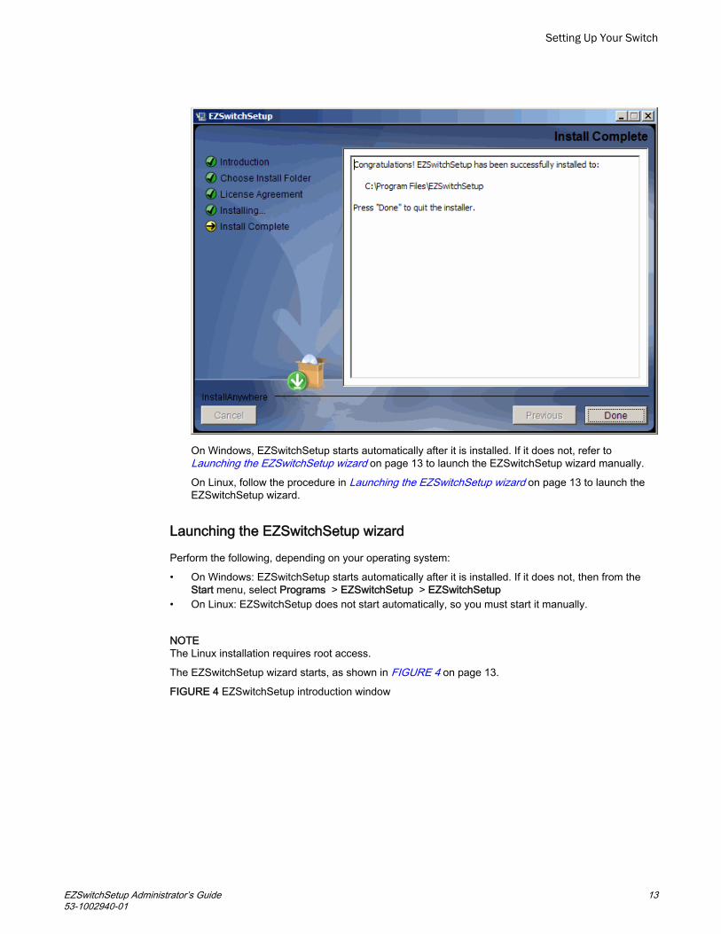
On Windows, EZSwitchSetup starts automatically after it is installed. If it does not, refer to Launching the EZSwitchSetup wizard on page 13 to launch the EZSwitchSetup wizard manually.
On Linux, follow the procedure in Launching the EZSwitchSetup wizard on page 13 to launch theEZSwitchSetup wizard.
Launching the EZSwitchSetup wizard
Perform the following, depending on your operating system:
• On Windows: EZSwitchSetup starts automatically after it is installed. If it does not, then from theStart menu, select Programs > EZSwitchSetup > EZSwitchSetup
• On Linux: EZSwitchSetup does not start automatically, so you must start it manually.
NOTEThe Linux installation requires root access.
The EZSwitchSetup wizard starts, as shown in FIGURE 4 on page 13.
FIGURE 4 EZSwitchSetup introduction window
Setting Up Your Switch
EZSwitchSetup Administrator’s Guide 1353-1002940-01

Connecting cables
1. Choose the method of connecting to your LAN.
You have the choice of using a serial connection or an Ethernet connection to your LAN to set theIP address for the switch. The Ethernet connection is generally more convenient and preferred.Use the serial connection if it is not possible or not convenient to connect the host on the samesubnet as the switch.
2. Click Next.
The Connect Cables window is displayed (FIGURE 5 on page 14).
FIGURE 5 Connect Cables window (Ethernet version, without serial cable)
Setting Up Your Switch
14 EZSwitchSetup Administrator’s Guide53-1002940-01

FIGURE 6 on page 16 shows the cables connecting to the Brocade Fibre Channel switch, setupcomputer, Ethernet hub or switch, and network.
NOTENot all switches have their serial and Ethernet connectors in the same place as in FIGURE 6 onpage 16. Refer to the hardware documentation to determine the correct placement of the serialand Ethernet connections.
Setting Up Your Switch
EZSwitchSetup Administrator’s Guide 1553-1002940-01

1 Brocade switch2 Power cable3 Ethernet hub or switch4 Serial cable5 Setup computer
6 Ethernet cable from hub to Brocade switch7 Ethernet cable from setup computer to Ethernet
hub or switch
FIGURE 6 Cable connections3. Connect the power cord to the switch and plug in to a power source.
The switch power and status LEDs display amber and then change to green, which usually takesfrom one to three minutes. Refer to your switch hardware manual for the location of the LEDs.
4. Connect an Ethernet cable from the Brocade switch to the LAN you want to use for yourmanagement connection through an Ethernet hub or switch. If you chose to use your Ethernetconnection for setup in step 1, this is the connection you will use. If you chose the serial cableconnection in step 1, you should still connect the Ethernet cable so the Ethernet connection willbe available when you start the EZSwitchSetup Switch Manager.
5. If you are using a serial connection for setup, connect your setup computer to the serial port onthe switch, using the serial cable shipped with the switch. If you cannot locate the serial cable thatcame with the switch, you will need to find one that has the appropriate connectors. Do not use anull-modem cable. The serial connection settings are as follows:
• Bits per second: 9600• Databits: 8• Parity: None• Stop bits: 1• Flow control: None
6. Click Next.
Setting Up Your Switch
16 EZSwitchSetup Administrator’s Guide53-1002940-01

EZSwitchSetup attempts to discover the switch. If your switch discovery fails, refer to TABLE 2 onpage 22 for details on how to recover your switch.
If you are using the serial connection, the Set Switch IP Address window is displayed, and you cango to step 5. You can now remove the serial cable from the switch, but keep it available in case youlose your network connection and need to revise any of the information you entered.
If you are using an Ethernet LAN connection, a Discover Switch window is displayed.
FIGURE 7 First Discover Switch window
Discovering the switch
1. Locate the WWN for your switch on the switch ID pull-out tab located on the bottom of the port sideof the switch.
2. From the Switch WWN list (FIGURE 7 on page 17), choose the switch’s WWN prefix numbers andthen enter the last six alphanumeric digits of your switch’s WWN. Each two alphanumeric digitsmust be separated by a colon.
3. Click Next.
When EZSwitchSetup discovers the switch, it displays the discovered IP addresses (IPv4 andIPv6), as shown in FIGURE 8 on page 17.
If you are setting up the switch for the first time, the IP addresses are placeholder addresses thatwere assigned at the factory and you must provide valid addresses.
FIGURE 8 Second Discover Switch window
Setting Up Your Switch
EZSwitchSetup Administrator’s Guide 1753-1002940-01

4. Select an option for assigning the IP address and click Next. The options vary depending on theconfiguration of your switch:
• Keep the current switch IP configuration
This option is available only if EZSwitchSetup detected a valid IP address. Skip to Confirming IPaddresses on page 19.
• Manually assign a new static IP address
If you select this option and click Next, the Set Switch IP Address window is displayed (FIGURE 9on page 18). Continue with step 5 to enter the IP address.
• Automatically obtain a valid IPv4 address
Select this option only if a DHCP server is available on your network. When you click Next, an IPaddress is automatically obtained from the DHCP server and the Confirm IP Address window isdisplayed. Skip to Confirming IP addresses on page 19.
FIGURE 9 Set Switch IP Address window
Setting Up Your Switch
18 EZSwitchSetup Administrator’s Guide53-1002940-01

NOTEBeginning at 5 on page 19, the steps are the same for both serial and Ethernet connections.
5. If you are setting up the switch for the first time, the addresses shown are not valid. If you click Nextwith these addresses in place, EZSwitchSetup returns an error message.
To set up IPv4 addresses, edit the address information on the Set Switch IP Address window tocreate static addresses appropriate for your LAN connection.
To set up IPv6 addresses, enter the IPv6 address and prefix in the spaces provided.6. Click Next.
EZSwitchSetup attempts to log in using default credentials. If you have already changed youradmin password, you will be prompted to enter your new password.
Proceed to Confirming IP addresses on page 19.
Confirming IP addresses
The Confirm IP Address window (FIGURE 10 on page 19) is displayed after you have assigned IPaddresses, using either a serial connection or an Ethernet connection.
FIGURE 10 Confirm IP Address window
Setting Up Your Switch
EZSwitchSetup Administrator’s Guide 1953-1002940-01

1. Check the displayed addresses carefully to be sure they are correct, then click Next.
The Continue Configuration? window is displayed (FIGURE 11 on page 20).2. Select one of the following continuation options:
• Continue setting up your target switch with EZManager
Select this option if you intend to use EZSwitchSetup Switch Manager as your primarymanagement program for this switch.
• Discover another switch on the same subnet for IP assignment only
Select this option to discover another switch and set the IP address.
If you select this option, EZSwitchSetup Switch Manager will not be the default management toolfor this current target switch. To set up EZSwitchSetup Switch Manager as the management toolfor this switch, you must discover it again with EZSwitchSetup and select the first continuationoption.
• Exit EZSwitchSetup
Select this option if you want to use EZSwitchSetup as an IP configuration tool, but do not want touse EZSwitchSetup Switch Manager as a management tool for the switch.
FIGURE 11 Continue Configuration?
Setting Up Your Switch
20 EZSwitchSetup Administrator’s Guide53-1002940-01

3. Click Continue.
Depending on the option selected, one of the following outcomes occurs:
• If you selected Continue setting up your target switch with EZManager, a dialog box displayswarning you that EZSwitchSetup supports only single-switch fabrics. Click OK to start theEZSwitchSetup Switch Manager.
A browser window opens, and the Switch Configuration Welcome window is displayed (FIGURE 12on page 23). This may take a few minutes.
If the EZSwitchSetup switch configuration wizard does not launch, you must launch it manually byspecifying the URL in a browser:
http://switch-ip-address
If the switch discovery fails, refer to Switch discovery failure on page 22 for details on how torecover your switch.
• If you selected Discover another switch on the same subnet for IP assignment only, theDiscover Switch window displays (FIGURE 7 on page 17). Go to Discovering the switch onpage 17 and provide the WWN for the next switch.
• If you selected Exit EZSwitchSetup, the EZSwitchSetup switch configuration wizard closes.
Setting Up Your Switch
EZSwitchSetup Administrator’s Guide 2153-1002940-01

Switch discovery failure
During the setup of your switch, the switch discovery may fail. There may be several reasons whyswitch discovery fails. TABLE 2 on page 22 lists symptoms and related suggestions to recover theswitch.
Discovery recovery TABLE 2
Symptom Correction
For serial connections:
The setup computer COM port isbusy.
The port is being controlled by another communications program. Stop allother third-party communications programs.
The port settings are in conflict with another device. Check your IRQsettings.
On Windows systems:
By default, COM1 and COM3 use IRQ4, while COM2 and COM4 use IRQ3.If another device is sharing the IRQ of the port, you must change the IRQ ofthe conflicting device. Hardware conflicts can also occur with the I/Oaddress of the COM port. The 8514a video chip or its clones (S3 chip set)on some video cards create a conflict with COM4 because they use thesame address of 02E8.
The switch does not respond tocommands during a serialconnection.
The serial cable may not be connected properly between the setupcomputer and the switch. Check the serial cable to ensure it is secured.
The switch does not power up. Verify that the switch’s power cable is securely plugged into a proper outletand that the switch’s power button is turned on.
The switch’s serial adapter does notwork.
Verify that the cable is good by replacing the cable or trying it on anotherknown working device.
If the cable is good, then call your support provider for further instructions.
For Ethernet connections:
The WWN is not entered correctly. Verify that the WWN is correct.
The target switch is not on thesame subnet as the host.
Connect the host to the same subnet as the target switch. If it is notpossible or convenient to do so, use the serial connection to set the IPaddress.
The target switch has no IP addressinstead of the factory default10.77.77.77.
Use the serial connection to set the IP address.
You have requested automaticaddress assignment in anenvironment where a DHCP serveris not available.
Use the serial connection to set a reachable address.
Setting Up Your Switch
22 EZSwitchSetup Administrator’s Guide53-1002940-01
Configuring the switch
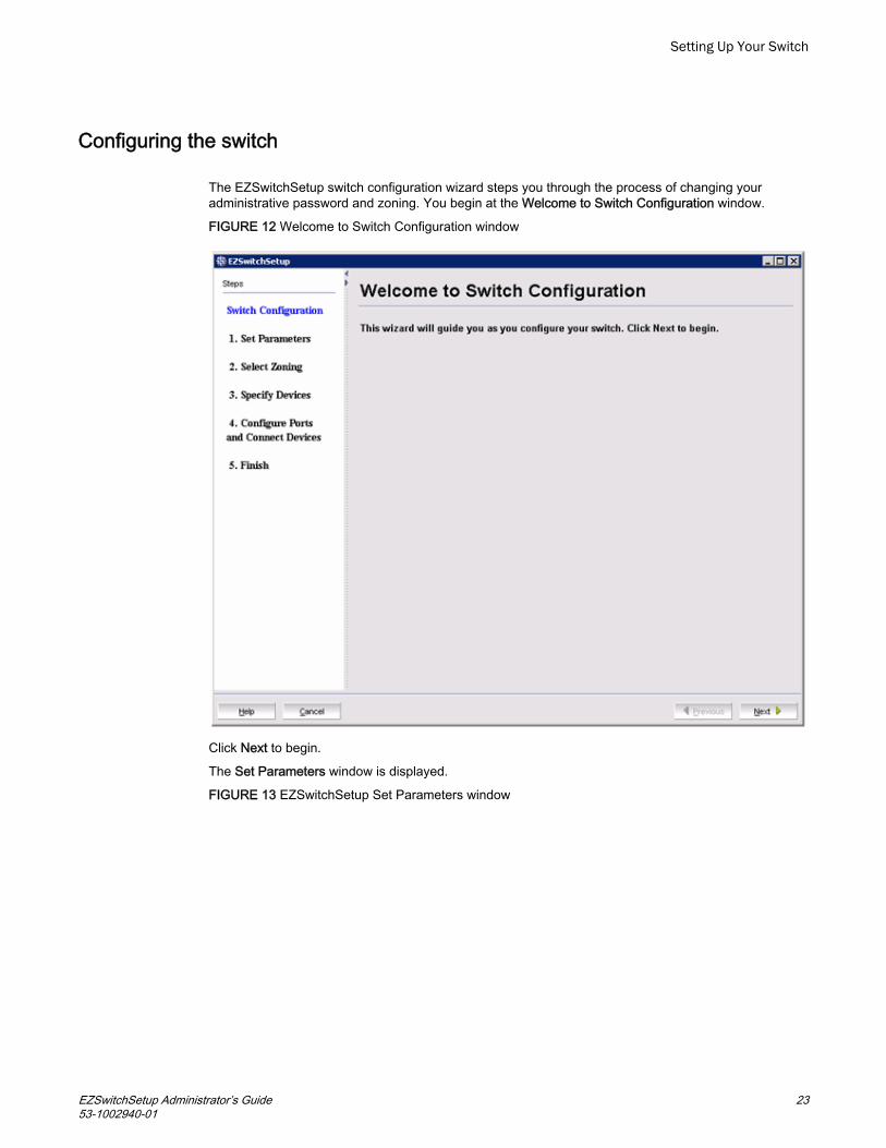
The EZSwitchSetup switch configuration wizard steps you through the process of changing youradministrative password and zoning. You begin at the Welcome to Switch Configuration window.
FIGURE 12 Welcome to Switch Configuration window
Click Next to begin.
The Set Parameters window is displayed.
FIGURE 13 EZSwitchSetup Set Parameters window
Setting Up Your Switch
EZSwitchSetup Administrator’s Guide 2353-1002940-01

Setting switch parameters
1. Follow the onscreen directions to set a new admin password for the switch. Make sure to recordyour password and keep it in a secure location for future reference.
2. Optional: Enter a new name for the switch and set the correct date and time.3. Click Next. The Select Zoning window is displayed.
Zoning selection options
The next step in configuring your switch is to select zoning. There are three choices:
• Typical Zoning creates a port-based zoning scheme based on the connections made on theConfigure Ports and Connect Devices window. This zoning scheme creates a two-member zonefor every possible pairing of HBA (H) and storage (S) ports connected on the Configure Ports andConnect Devices window. This ensures that any host device connected to an H port is able tocommunicate with any storage device connected to an S port.
NOTEYou can use Typical Zoning for dual-capable devices (devices that are configured to function both asinitiators and targets), but in Typical Zoning mode, these devices are recognized as targets byEZSwitchSetup and are rejected if attached to a host port.
Setting Up Your Switch
24 EZSwitchSetup Administrator’s Guide53-1002940-01

• Custom Zoning allows you to customize which initiators access which targets, and creates adevice-based zoning scheme based on your choices. The HBAs and storage devices shouldalready be connected to the switch. Custom Zoning provides a device accessibility matrix for you tomodify; it then automatically creates zones based on that matrix. Custom Zoning supports onlysingle-switch fabrics. If you select this option, when you click Next, the EZSwitchSetup switchconfiguration wizard closes and the EZSwitchSetup Switch Manager application opens.
• Advanced Zoning allows you complete customization of your zoning and should be used if you arefamiliar with zoning and zoning practices. If you select this option, when you click Next, theEZSwitchSetup switch configuration wizard closes and the Advanced Management application(Web Tools) opens. For specific information about using Web Tools for zoning, refer to the WebTools Administrator's Guide.
FIGURE 14 Select Zoning window
Typical Zoning is the default and the following procedure directs you to select Typical Zoning. When youselect Typical Zoning, the EZSwitchSetup switch configuration wizard automatically configures thezones for you and shows you how to connect the devices to the switch.
Configuring zones on the switch
1. On the Select Zoning window (Figure 14), select Typical Zoning.
If you want to use one of the other zone settings, refer to “Editing the zoning configuration” on page43 for instructions on configuring Custom Zoning; refer to the Web Tools Administrator's Guide forinformation on Advanced Zoning.
2. Click Next.
Setting Up Your Switch
EZSwitchSetup Administrator’s Guide 2553-1002940-01

The Specify Devices window is displayed.
Specifying devices
On the Specify Devices window, complete the following steps.
1. Enter the number of HBA connections that you want to attach to the switch. Be sure to includeexisting HBA connections, and any additional HBA connections you plan to make in the currentsetup session. You can change this setting later if you want to add or remove HBA connections.
2. Enter the number of storage connections you want to attach to the switch. Be sure to includeexisting storage connections, and any additional storage connections you plan to make in thecurrent setup session. You can change this setting later if you want to add or remove storageconnections.
EZSwitchSetup uses these values to verify that all your current and planned devices are properlyconnected for the zoning scheme that will be created. Note that Typical Zoning ensures that everyconnected host device will be able to communicate with every connected storage device.
3. Click Next. The Configure Ports and Connect Devices window is displayed.FIGURE 15 Specify Devices window
Connecting devices and completing the setup
The final step in the switch configuration is to connect your devices to the switch in a way that matchesa configured array of connection reservations (HBA or storage) on the ports. In the interactive switch
Setting Up Your Switch
26 EZSwitchSetup Administrator’s Guide53-1002940-01

graphic that is displayed on the Configure Ports and Connect Devices window, these connectionreservations are shown by the letters H or S against a blue or green background on the ports, and willautomatically match the types of the devices that have already been connected, with existingconnections shown as green lines that connect the ports with icons representing the devices. If youhave indicated on the Specify Devices window that you intend to connect more devices, connectionreservations of matching types will also have been made for your planned devices, with dotted bluelines to show you where these devices should be attached. Finally, as you attach the new devices, thedotted blue lines will change to solid green (for correctly attached devices) or to solid red (when devicesare attached at ports with non-matching reservations). When a red line appears, the mismatch may becorrected either by moving the device to a different port as suggested by a dotted blue line for a deviceof that type, or by changing the reservation type of the port where the device is currently connected byclicking on the port icon. In either case, the solid red and dotted blue lines should both disappear, andbe replaced by a single solid green line to indicate the correct connection. For connected devices, youcan also view details of the device by pausing on the host or storage icon.
The Next button for this window is not enabled until all non-matching or missing connection issues(indicated by solid red and dotted blue lines) have been resolved.
If you change your mind about the number of devices you want to connect, you can click the Previousbutton and adjust the values you have selected in the device type lists on the Specify Devices window.You must always select at least as many devices of each type as have been connected, and you mustalso connect as many devices of each type as you have selected. On the Configure Ports and ConnectDevices window, you can also pre-reserve some additional currently unoccupied ports for future HBA orstorage connections. These additional reservations are also reflected in the zoning scheme, and areshown on the Devices view window in the EZSwitchSetup Switch Manager application to remind youwhere these additional devices can be connected. The default reservation type is HBA.
FIGURE 16 Configure Ports and Connect Devices window
Setting Up Your Switch
EZSwitchSetup Administrator’s Guide 2753-1002940-01

When you click Next on the Configure Ports and Connect Devices window, if Typical Zoning is used,the final set of connection reservations shown on the window is translated internally into a zoningscheme that ensures that every correctly connected host device can communicate separately withevery correctly connected storage device. If this is not what you want (for example, if you want topartition your devices so that each HBA can communicate with some storage devices but not others),then you should re-run the EZSwitchSetup switch configuration wizard and select Custom Zoning orAdvanced Zoning instead of Typical Zoning.
Use the following procedure to make the physical connections.
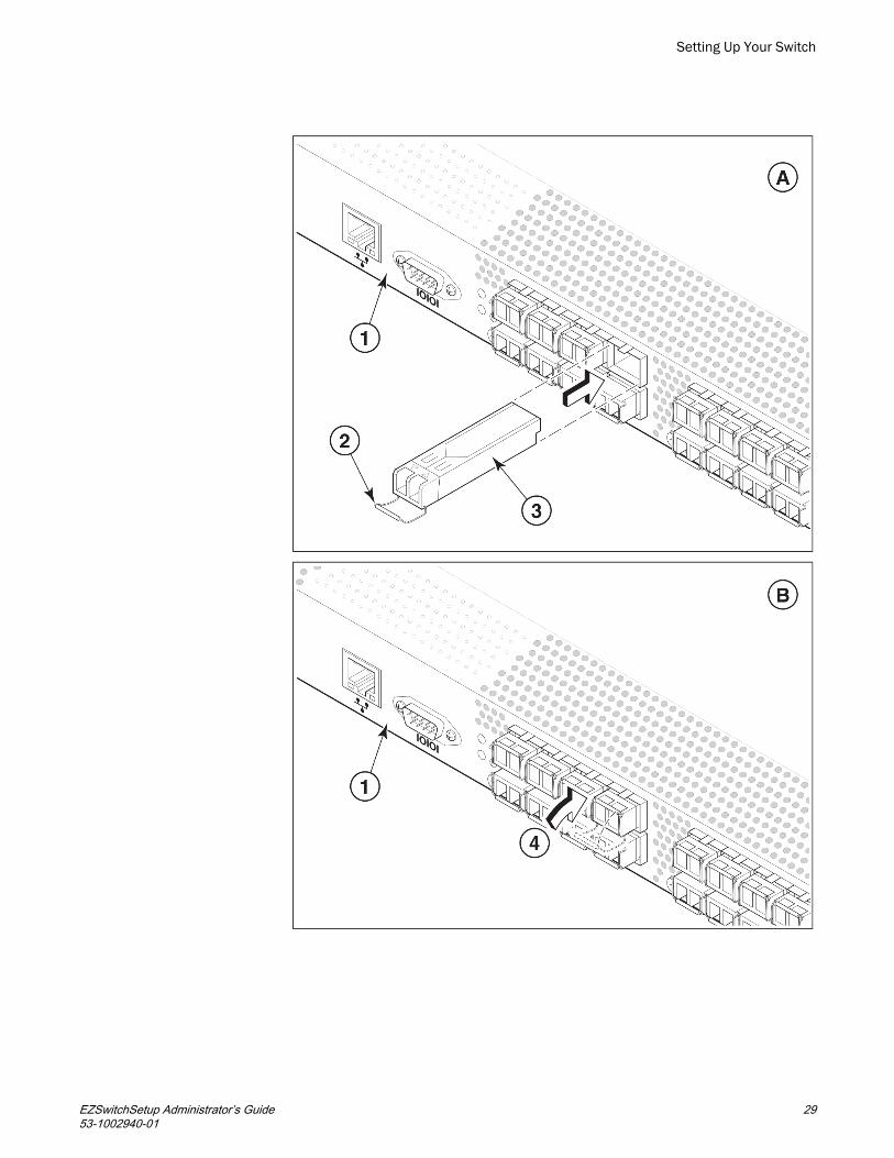
1. Install the small form-factor pluggable (SFP) transceivers in the Fibre Channel ports shownonscreen. (Refer to FIGURE 16 on page 27.)a) Remove any protector plugs from the SFP transceivers to be used.b) Position and insert each SFP transceiver as required (right side up in the top row of ports
and upside down in the bottom row of ports) until it is firmly seated.c) Close the latching bale.
Setting Up Your Switch
28 EZSwitchSetup Administrator’s Guide53-1002940-01
Setting Up Your Switch
EZSwitchSetup Administrator’s Guide 2953-1002940-01

1 Brocade switch2 Open the SFP latching bale
3 Position SFP and insert untilfirmly seated
4 Close the latching bale
FIGURE 17 Installing SFP transceivers2. Connect Fibre Channel cables from the switch to your host and storage devices. Ensure that the
physical connections are exactly as indicated on the Configure Ports and Connect Deviceswindow.a) Remove any plastic protectors from the Fibre Channel cable ends, and position the cable
connector so that it is oriented correctly.b) Insert the cable connector into the SFP transceiver until it is firmly seated and the
latching mechanism clicks, as shown in FIGURE 18 on page 30.
The Configure Ports and Connect Devices window provides visual feedback as youcable the switch. A green line indicates that the connection is correct, a red line indicatesan invalid connection, and a blue line indicates a missing connection.
1 Position the Fibre Channel cable2 Install the Fibre Channel cable3 Brocade switch
FIGURE 18 Installing Fibre Channel cable into an SFP transceiver3. Verify that the connections displayed on the Configure Ports and Connect Devices window are all
green.4. Click Next .
The EZSwitchSetup Configuration Finish window is displayed.
FIGURE 19 EZSwitchSetup Configuration Finish window
Setting Up Your Switch
30 EZSwitchSetup Administrator’s Guide53-1002940-01

5. Click Finish to complete the switch setup.
You are now ready to configure the storage component of the SAN using the documentation thatcame with the storage server.
If you want to monitor the switch, then you need to launch the EZSwitchSetup Switch Manager.Refer to Managing Your Switch on page 32 for instructions on using this interface.
Setting Up Your Switch
EZSwitchSetup Administrator’s Guide 3153-1002940-01

Managing Your Switch● Switch Manager overview......................................................................................32● Launching the EZSwitchSetup Switch Manager....................................................35● Viewing switch information.....................................................................................37● Changing switch information..................................................................................43● Adding a port license............................................................................................. 43● Managing devices..................................................................................................44● Zoning management..............................................................................................50● Accessing Web Tools for advanced management.................................................55
Switch Manager overview
The EZSwitchSetup Switch Manager is a simplified version of Web Tools. It streamlines switchmanagement by providing an easy-to-use subset of basic switch management tasks.
You can use the EZSwitchSetup Switch Manager to perform the following functions:
• Monitor the switch, including port and field-replacable unit (FRU) status• Manage Custom Zoning• Perform basic switch configurations• Add Ports on Demand (POD)
The Switch Manager works for a single-switch fabric only. It displays only the switch and associatedtasks, without fabric information.
FIGURE 20 on page 32 shows an example of the initial Switch Manager window. The appearancemay vary depending on the switch model. The following sections describe the components of thewindow.
FIGURE 20 EZSwitchSetup Switch Manager components
Managing Your Switch
32 EZSwitchSetup Administrator’s Guide53-1002940-01

1 Tasks panel2 Content page3 Status bar
4 Progress indicator5 User name, IP address, and user role
Tasks panel
The left pane of the Switch Manager is the tasks panel, which displays all tasks:
• Switch tasks enable you to view the port information or switch information, enter into switch setup,or add port licenses.
• Devices tasks enable you to view the devices attached to the switch, display the deviceconnections, and modify a device alias.
• Zoning tasks enable you to view the zoning on the device, edit the zoning, validate the zoning, orrestore the default typical zoning.
• Miscellaneous tasks include refreshing the onscreen data, advanced management of the switch,and logging out.
The switch’s Port Information tab is shown by default when Switch Manager launches.
Switch View
The Switch View displays a graphical view of the switch, and contains a set of status buttons. Thestatus buttons (Fan, Temp, and Power) enable access to status information for each listed element.
Managing Your Switch
EZSwitchSetup Administrator’s Guide 3353-1002940-01

Click Refresh under Miscellaneous to update the information on the window with the current switchinformation. The display refreshes automatically each time you select a different task in the Taskspanel.
Content page
When you select a task in the Tasks panel, the content for that task displays in the content page of thewindow. A content page may contain tabs, display information, launch a wizard, or display a dialogbox. Figure 21 shows the information displayed on the Port Information tab, and shows a shortcutmenu that provides copy and export functions.
FIGURE 21 Content page, Port Information tab
NOTEYou must accept the Brocade Certificate at the beginning of the login to EZSwitchSetup SwitchManager to enable the copy and export functions.
• Click Export Row or Export Table to save the information to a tab-delimited text file.• Click Copy ‘text’, Copy Row, or Copy Table to copy the contents of the table in tab-delimited text
format that can be pasted into a spreadsheet. Copy ‘text’ copies only the contents of the selectedcell, Copy Row copies the entire row, and Copy Table copies the entire table.
• Click Search to search for a specific text string in the table.
Type a text string in the field that displays on the table, and press Enter. This is an incremental searchand allows a maximum of 24 including the wildcard characters: question mark (?) and asterisk (*). Thefirst row containing the text string is highlighted. To find the next match, press the down arrow. To findthe previous match, press the up arrow.
If the text string is not found in the table, the text turns red.
Managing Your Switch
34 EZSwitchSetup Administrator’s Guide53-1002940-01

Status bar
The status bar appears at the bottom of the window is divided into the following sections:
• Progress indicator
When Switch Manager is sending data to or retrieving data from the switch, this indicator is animated.
• User name and IP address
The status bar displays your user name, role, and the IP address of the switch to which you areconnected.
Launching the EZSwitchSetup Switch Manager
You can launch Switch Manager on any workstation with a compatible browser installed. For a list ofcompatible browsers, refer to Table 1 on page 2. Switch Manager also supports HTTPS, if that protocolis enabled for the switch. For more information on enabling HTTPS on your switch, refer to the FabricOS Administrator's Guide.
1. Launch a browser and type the IP address of the switch in the Address field, and press Enter.FIGURE 22 Java Web Start dialog box
If this is the first time the application has been started, a Warning - Security dialog box is alsodisplayed.
FIGURE 23 Warning - Security dialog box
Managing Your Switch
EZSwitchSetup Administrator’s Guide 3553-1002940-01

2. If the Warning - Security dialog box is displayed, select Always trust content from this publisherand click Run.
The Login dialog box is displayed.
FIGURE 24 Login dialog box
Logging in
If the switch is set up and configured with EZSwitchSetup, the EZSwitchSetup Switch Managerlaunches when you log in to EZSwitchSetup Switch Manager. If not, Web Tools launches.
Switch Manager supports only single-switch fabrics. If your switch is connected to another switch,Switch Manager displays a message and exits. You must disconnect the switch from all other switchesand relaunch EZSwitchSetup Switch Manager.
1. Type your user name and password.2. Click OK.
A Switch Manager session is established, and the Switch View is displayed.
Managing Your Switch
36 EZSwitchSetup Administrator’s Guide53-1002940-01

Switch Manager sessions
A session is defined as the connection between the Switch Manager client and its managed switch. Asession is established when you log in to a switch through EZSwitchSetup. A session remains in effectuntil you log out or the session times out due to inactivity.
Logging out
You can end your Switch Manager session either by selecting Log Out under Miscellaneous in theTasks panel, or by closing the browser window. All windows belonging to the session are invalidated(after a short delay they appear dimmed and unavailable, but you must close them manually), and thesession is terminated.
Viewing switch information
Using EZSwitchSetup Switch Manager, you can view the following:
• Switch status, including port status• Temperature, fan, and power supply status• HBA and storage connections to the switch• Information about devices connected to the switch• Accessibility between HBAs and storage
To view the Switch information, perform the following steps.
1. Click View in the Tasks panel under Switch.2. Click the Switch Information tab to display the Switch View.
FIGURE 25 on page 37 displays the Switch View for a Brocade 6520 switch.
FIGURE 25 Graphical view of switch
Managing Your Switch
EZSwitchSetup Administrator’s Guide 3753-1002940-01

The Switch View is a real-time view of switch and port status. The display is updatedapproximately once every 15 seconds. From the display you can determine the following:
• Fan status• Temperature status• Power supply status• Status and type of each port
Viewing the status indicator legend
The Fan, Temp, and Power buttons indicate overall status:
• Green circle (healthy)• Yellow triangle (marginal)• Red diamond (critical)• Black and yellow striped square (unmonitored)
To view the legend for the status indicators, click the Legend button.
The legend view opens. FIGURE 26 on page 38 shows the status indicators that can appear on theFan, Temp, and Power buttons.
FIGURE 26 Fan, temperature, and power supply legend
Managing Your Switch
38 EZSwitchSetup Administrator’s Guide53-1002940-01

Viewing fan, temperature, and power supply status
To view fan, temperature, or power supply status, click the Fan, Temp, or Power button.
FIGURE 27 on page 39 shows the Fan view. The Fan view shows the number of fans and theiroperating states.
FIGURE 27 Fan status
FIGURE 28 on page 39 shows the Temperature view. The Temperature view displays the number oftemperature sensors, their status, and the temperature in Centigrade and Fahrenheit.
FIGURE 28 Temperature status
Managing Your Switch
EZSwitchSetup Administrator’s Guide 3953-1002940-01

FIGURE 29 on page 40 shows the Power Supply view. The Power Supply view displays the numberof power supplies in the switch and their status.
FIGURE 29 Power supply status
Port status
The Switch View displays port graphics with blinking LEDs, simulating the physical appearance of theports. One or two LEDs are associated with each port, depending on the switch model. One of theLEDs indicates port status, while the other indicates port speed. For LED information, refer to thehardware documentation for the switch you are viewing.
NOTEAll of the 8 Gbps and 16 Gbps Brocade switches do not have port speed LEDs, but only port statusLEDs.
The background color of the port icon indicates the port status:
• Green (healthy)• Yellow (marginal)
Managing Your Switch
40 EZSwitchSetup Administrator’s Guide53-1002940-01
• Red (critical)• Gray (unmonitored)
If the entire port icon is blue, the port is buffer-limited. A port is operating in buffer-limited mode whenthe number of buffers allocated to the port is less than the number of buffers needed by the port toutilize the port at full bandwidth.
If a group of port icons is gray (unmonitored), those ports are not licensed.
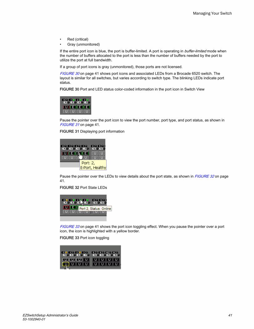
FIGURE 30 on page 41 shows port icons and associated LEDs from a Brocade 6520 switch. Thelayout is similar for all switches, but varies according to switch type. The blinking LEDs indicate portstatus.
FIGURE 30 Port and LED status color-coded information in the port icon in Switch View
Pause the pointer over the port icon to view the port number, port type, and port status, as shown in FIGURE 31 on page 41.
FIGURE 31 Displaying port information
Pause the pointer over the LEDs to view details about the port state, as shown in FIGURE 32 on page41.
FIGURE 32 Port State LEDs
FIGURE 33 on page 41 shows the port icon toggling effect. When you pause the pointer over a porticon, the icon is highlighted with a yellow border.
FIGURE 33 Port icon toggling
Managing Your Switch
EZSwitchSetup Administrator’s Guide 4153-1002940-01

Switch Information tab
The Switch Information tab is the default information tab under Port Information, Switch Information onthe Switch View (FIGURE 34 on page 42). Detailed switch information is displayed as a list ofproperties, which may be viewed, copied, or exported by category.
FIGURE 34 Switch Information tab
Port Information tab
Select the Port Information tab to view the port information (FIGURE 35 on page 42). Detailed portinformation is displayed as a categorized list of properties, which may be viewed, copied, or exportedby category.
FIGURE 35 Port Information tab
Managing Your Switch
42 EZSwitchSetup Administrator’s Guide53-1002940-01

Changing switch information
From the Switch Manager, you can relaunch the EZSwitchSetup switch configuration wizard to performthe following tasks:
• Change the switch name.• Change the switch time.• Change the admin password.• Change the zoning configuration type.
EZSwitchSetup switch configuration wizard was launched the first time you set up the switch.
1. Click Setup under Switch in the Tasks panel.
The EZSwitchSetup switch configuration wizard launches.2. Follow the instructions in the wizard.
You can optionally change the switch name, switch time, and admin password. When prompted,you must select a zoning configuration.
Adding a port license
EZSwitchSetup Switch Manager allows you to enable Ports on Demand (POD) if you have a licenseavailable. For example, for the Brocade 7800, you can add the 7800 Upgrade License to activate ports4-25. This option is not available if all ports are already licensed.
1. Click Add Port License under Switch in the Tasks panel.
The Add Port License dialog box is displayed.
FIGURE 36 Add Port License dialog box
Managing Your Switch
EZSwitchSetup Administrator’s Guide 4353-1002940-01

2. Enter the license key to add the additional ports.3. Click Add License.
The ports can now be enabled.4. Enable the ports using one of the following methods:
• Reboot or power cycle the switch.
When the switch is rebooted, the newly licensed ports come up as enabled.
• Use the Advanced Management tool.
Refer to Accessing Web Tools for advanced management on page 55 for information onlaunching Web Tools.
• Use the command line interface.
Refer to the Fabric OS Administrator's Guide for information on using the command line interface.
Managing devices
The Devices view displays the following information:
• Whether the device is an HBA, an HBA plus storage, or a storage-only device• Device alias name, if one exists• Vendor name• Device name• WWN of the device port• Switch and port to which the device is connected
1. Click View under Devices in the Tasks panel to display a table of information for all of theconnected devices (FIGURE 37 on page 44).
The entries in the table are based on the device WWNs, so a single physical device can havemore than one entry in the table. The device information can be viewed, copied, or exported.
FIGURE 37 Devices view
Managing Your Switch
44 EZSwitchSetup Administrator’s Guide53-1002940-01
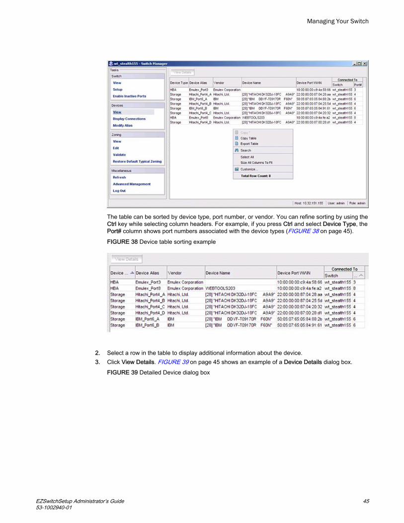
The table can be sorted by device type, port number, or vendor. You can refine sorting by using theCtrl key while selecting column headers. For example, if you press Ctrl and select Device Type, thePort# column shows port numbers associated with the device types (FIGURE 38 on page 45).
FIGURE 38 Device table sorting example
2. Select a row in the table to display additional information about the device.3. Click View Details. FIGURE 39 on page 45 shows an example of a Device Details dialog box.
FIGURE 39 Detailed Device dialog box
Managing Your Switch
EZSwitchSetup Administrator’s Guide 4553-1002940-01

Device connections
Click Display Connections under Devices in the Tasks panel.
EZSwitchSetup Switch Manager displays a graphical representation of the switch and the devices thatare connected to each port, as shown in FIGURE 40 on page 46. This is a real-time display; theconnections are updated automatically as you connect and disconnect HBAs and storage.
If Typical Zoning is set on the switch, Switch Manager validates the connections and displays whetherthe connections are valid or invalid. Switch Manager also shows what currently unoccupied ports areavailable for host and storage connections.
FIGURE 40 Display Connections window
Managing Your Switch
46 EZSwitchSetup Administrator’s Guide53-1002940-01

Assigning and renaming device aliases
Every device has a device name and an alias. Aliases make it easier to reference the devices. Aliasesare displayed in the zone access map on the Zoning page. You can assign or rename the alias usingthe following procedure.
1. Select Modify Alias under Devices in the Tasks panel.
The Define Device Aliases wizard is displayed. The first time the Define Device Aliases wizard isstarted, the New Alias column is populated with default aliases. You can click OK to accept thedefault aliases, or click Cancel if you do not want to assign aliases.
NOTEIf an alias is not assigned, the device is identified by WWN only.
A good alias makes it much easier to identify devices.
If you want to edit the alias, go on to step 2.
FIGURE 41 Define Device Aliases wizard window
Managing Your Switch
EZSwitchSetup Administrator’s Guide 4753-1002940-01

2. Double-click a field in the New Alias column and edit the alias.3. Click OK when you are done.
A “Zone commit succeeded” message is displayed. This message confirms that the device aliaschanges have been saved to the zoning database. The Define Device Aliases wizard alsoprompts you to delete the aliases of any offline devices.
The next time you select Modify Alias, the Current Alias column is populated with the New Aliasnames (FIGURE 42 on page 48).
FIGURE 42 Device aliases moved under Current Aliases column
Managing Your Switch
48 EZSwitchSetup Administrator’s Guide53-1002940-01

After you have defined the device aliases, the aliases are displayed in the Device Alias columnwhen you select View under Devices in the Tasks panel (as in FIGURE 37 on page 44). The devicealiases are also displayed in the Zone Access Map for Devices when you select View under Zoningin the Tasks panel (FIGURE 43 on page 49).
FIGURE 43 Device alias in Zone Access Map for Devices
Managing Your Switch
EZSwitchSetup Administrator’s Guide 4953-1002940-01

Zoning management
Zoning enables you to partition your fabric into logical groups of devices that can access each other.For example, you can partition your fabric into two zones, winzone and unixzone, so that yourWindows servers and storage do not interact with your UNIX servers and storage.
Zones can be configured dynamically. They can vary in size, depending on the number of fabric-connected devices, and devices can belong to more than one zone. Because zone members canaccess only other members of the same zone, a device not included in a zone is not available tomembers of that zone.
Zone members may be specified by fabric location (domain, port index) only, or by device name (nodename or port WWN). Zones with members that are specified by fabric location are port-based, andzones with members that are directly specified by device WWN are device-based. In port-basedzoning, all devices that are connected to ports that are in the same zone can communicate with eachother, and a device can join a zone simply by being connected to a member port. In device-basedzoning, devices are explicitly specified as members of the same zone. These devices cancommunicate with each other regardless of where they are located in the fabric.
Managing Your Switch
50 EZSwitchSetup Administrator’s Guide53-1002940-01

EZSwitchSetup creates zones for you automatically, based on your configuration choices during setupin the EZSwitchSetup switch configuration wizard.
• If you choose Typical Zoning, a port-based zoning scheme is created. This zoning scheme createsa two-member zone for every possible pairing of H and S ports connected on the Configure Portsand Connect Devices window. This ensures that any host device connected to an H port is able tocommunicate with any storage device connected to an S port. This remains true even if you move adevice, assuming you connect the device to the correct type of port (H or S).
• If you choose Custom Zoning, you create a device accessibility matrix during setup. The deviceaccessibility matrix creates a device-based zoning scheme. By default, every connected hostdevice can communicate with every connected storage device, as in Typical Zoning. You can usethe device accessibility matrix to selectively disallow communications between certain devices,creating a device-partitioning scheme that is enforced by zoning. Because Custom Zoning isdevice-based, you may freely move your devices to different ports without affecting accessibilityrelationships. If you add or permanently remove devices, you should reconfigure the accessibilitymatrix.
• If you choose Advanced Zoning, you are given direct access to the zoning database through WebTools, and you can create a zoning scheme of your own. EZSwitchSetup Switch Manager canvalidate and display accessibility relationships based on your scheme, and it can replace yourscheme with Typical Zoning or Custom Zoning. If you want to edit your scheme, you must return tothe EZSwitchSetup switch configuration wizard and select Advanced Management to start WebTools. For specific information about using Web Tools for zoning, refer to the Web ToolsAdministrator's Guide.
Viewing the Zone Access Map for Devices
Click View under Zoning in the Tasks panel to view the Zone Access Map for Devices. If you have nodevices or if you have only one device, the matrix map does not display.
The HBA and storage device names displayed in the matrix are the aliases of the devices (refer to Assigning and renaming device aliases on page 47 for additional information). If no aliases areassigned, devices are identified by WWN. When aliases are assigned, you can refer to the WWN bypausing the pointer over the alias in the matrix.
FIGURE 44 Zone Access Map for Devices
Managing Your Switch
EZSwitchSetup Administrator’s Guide 5153-1002940-01

Some HBAs and storage devices can be configured with dual initiator and target capability. Suchdevices are displayed as both HBA and storage devices in the matrix.
Editing the zoning configuration
You can customize which HBAs can access which storage devices by clicking Edit under Zoning in theTasks panel. This starts a wizard that creates a new Custom Zoning scheme based on your deviceaccessibility choices.
If you make any zoning changes to the default Typical Zoning configuration, you create a CustomZoning configuration to replace it. You can later restore the Typical Zoning configuration by clickingRestore Default Typical Zoning in the Tasks panel.
1. Click Edit under Zoning in the Tasks panel.
A wizard launches, briefly displaying the Zone Access Map for Devices.
A Review Device Connections dialog box displays device connections over the Zone Access Mapfor Devices. Make sure all connected devices are present and recognized by the switch.
2. Click Next.
The Define Device Aliases window is displayed.3. Add or modify aliases in the New Alias column.4. Click Next.
The Edit HBA/Storage Accessibility Matrix window is displayed.
Managing Your Switch
52 EZSwitchSetup Administrator’s Guide53-1002940-01
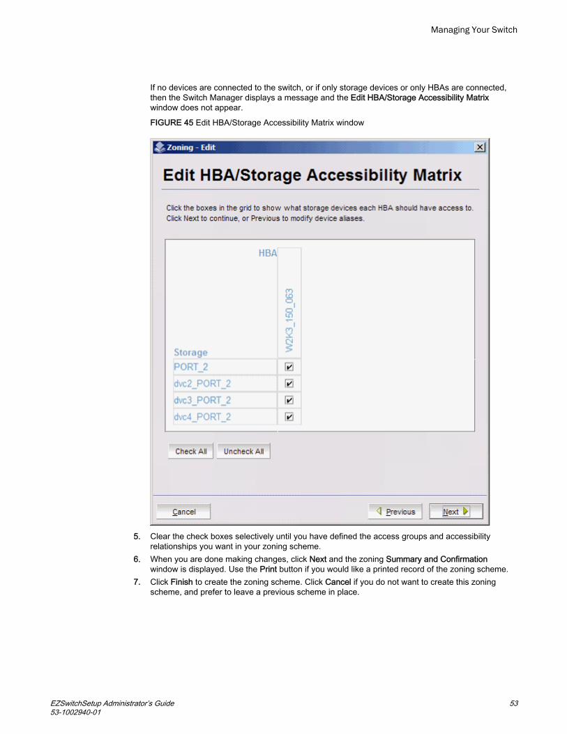
If no devices are connected to the switch, or if only storage devices or only HBAs are connected,then the Switch Manager displays a message and the Edit HBA/Storage Accessibility Matrixwindow does not appear.
FIGURE 45 Edit HBA/Storage Accessibility Matrix window
5. Clear the check boxes selectively until you have defined the access groups and accessibilityrelationships you want in your zoning scheme.
6. When you are done making changes, click Next and the zoning Summary and Confirmationwindow is displayed. Use the Print button if you would like a printed record of the zoning scheme.
7. Click Finish to create the zoning scheme. Click Cancel if you do not want to create this zoningscheme, and prefer to leave a previous scheme in place.
Managing Your Switch
EZSwitchSetup Administrator’s Guide 5353-1002940-01

If you click Finish, allow time for the new scheme to be created. The Zone Access Map forDevices is updated with any new aliases, and a Zone commit succeeded confirmation dialog boxis displayed.
8. Dismiss the confirmation dialog box. The Zone Access Map is updated to show the newaccessibility relationships.FIGURE 46 Zoning summary information
Validating zoning configuration
You can validate the current zoning configuration against the following rules:
• Every HBA has access to at least one storage device.• Every storage device is accessible by at least one HBA.• No offline devices exist in the zoning configuration.
If offline devices are in the current zoning setup, you are prompted to delete those devices from thezoning database.
1. Click Validate under Zoning in the Tasks panel.
The Validate Zoning wizard launches.2. Follow the instructions in the wizard.3. Note any devices that are not zoned properly and, after exiting the wizard, click Edit to update the
zone configuration.
Managing Your Switch
54 EZSwitchSetup Administrator’s Guide53-1002940-01

Restoring Typical Zoning
If you have modified your zoning configuration and want to reset the configuration back to the defaultTypical Zoning configuration, use the following procedure.
1. Click Restore Default Typical Zoning under Zoning in the Tasks panel.2. Click Yes in the confirmation window.
When this task is complete, the matrix in the Zone Access Map for Devices page is automaticallyupdated to reflect the changes.
Accessing Web Tools for advanced management
From the Switch Manager, you can launch Web Tools, which provides more extensive switchmanagement functions for more experienced users. Refer to the Web Tools Administrator’s Guide forinformation on the Web Tools interface.
To launch Web Tools, ensure that you have completed all Switch Manager tasks and then clickAdvanced Management under Miscellaneous in the Tasks panel. The Switch Manager session will becloses. Any editing in Switch Manager that has not been applied is lost.
After entering Web Tools, you must log in again to manage the switch.
You cannot return to EZSwitchSetup Switch Manager unless you close and re-open your browserwindow and relaunch EZSwitchSetup.
Making EZSwitchSetup your default switch manager
If you want to be sure that the EZSwitchSetup Switch Manager is launched as the default switchmanagement program from your browser instead of Web Tools, complete the following steps.
1. Log in to the switch.2. Enter the configure command and type yes or y to display Web Tools attributes, as shown in the
following example.
switch:admin> configure Not all options will be available on an enabled switch.To disable the switch, use the "switchDisable" command. Configure... System services (yes, y, no, n): [no] ssl attributes (yes, y, no, n): [no] rpcd attributes (yes, y, no, n): [no] webtools attributes (yes, y, no, n): [no] yWeb Tools attributes are displayed.
3. Type yes or y for the Basic User Enabled attribute to make the EZSwitchSetup Switch Managerstart by default from your browser rather than Web Tools, as in the following example.
Basic User Enabled (yes, y, no, n): [yes] yIf no or n is specified, Web Tools is launched. Note that no is the default value.
Managing Your Switch
EZSwitchSetup Administrator’s Guide 5553-1002940-01

EZSwitchSetup Limitations● General limitations................................................................................................. 56
General limitations
TABLE 3 on page 56 lists general EZSwitchSetup Switch Manager limitations, which apply to allbrowsers and switch platforms.
EZSwitchSetup Switch Manager limitations TABLE 3
Problem area Details
HTTP timeout Very often, you may see the following message when you try to retrieve data from a switch orsend a request to the switch:
Failed to get switch response. Please verify the status of your last operation and try again ifnecessary.
This indicates that an HTTP request did not get a response. The request was sent to the switch,but the connection was down, probably caused by a temporary loss of the web server on theswitch. Due to the nature of an HTTP connection, Switch Manager will report this error after a 90-second default timeout.
In this case, verify the status of your last request, using Telnet to check related status, or click theRefresh button in the Switch Manager to retrieve related data. If your request did not get throughto the switch, resubmit it. Executing a refresh from Switch Manager retrieves a copy of switchdata at that moment; the data you entered can be lost if it had not already been committed to theswitch.
Loss ofconnection
Occasionally, you may see the following message when you try to retrieve data from the switchor send a request to the switch:
Switch Status Checking
The switch is not currently accessible.
The dialog box title may vary, because it indicates which module is having the problem.
This is caused by the loss of an HTTP connection with the switch due to a variety of possibleproblems. Switch Manager automatically tries to regain the connection. While Switch Manager istrying to regain the connection, check if your Ethernet connection is functioning. If the problem isnot with the Ethernet connection, wait for Switch Manager to recover the connection and displaythe following message:
You will have to resubmit your request after closing this message.
If the temporary switch connection loss is caused by a switch hot code load or other similaroperation, the Switch Explorer you are currently running can be downloaded from a differentfirmware version than the new one. In this case, the following message displays:
Switch connection is restored. The firmware version you are running is not in sync with theversion currently on switch. Close your browser and re-launch Web Tools.
You must close Switch Manager and relaunch it to reopen the connection.
EZSwitchSetup Limitations
56 EZSwitchSetup Administrator’s Guide53-1002940-01

Index
Aaccessing Web Tools from EZSwitchSetup 55admin password, changing 43
Bbrowsers
limitations 56refresh frequency, setting 9supported 8
Cchanging switch information 43CIDR block 17closing sessions 37COM port is busy. setup computer 22configuring Internet Explorer 9connecting Fibre Channel cables 26
DDevice Details dialog box 44device information, displaying 44displaying
device information 44port information 40, 42
EEdit HBA/Storage Accessibility Matrix window 52enabling ports 43ending sessions 37EZSwitchSetup
about 32installing 12launching 35
EZSwitchSetup switch configuration wizard, launching43EZSwitchSetup wizard launch 13
FFan, Temperature, and Power Supply Legend 38fan status 37Fibre Channel cables, connecting 26
Hhardware, supported 10HTTPS protocol 35
Iinactivity timeout 37installing
EZSwitchSetup 12IPv6 address 17
JJRE, minimum version requirements 8
Llanguages supported 11launching EZSwitchSetup 35LEDs 40limitations 56localization support 11logging in 36logging out 37
Mmonitoring the switch 37
Ooperating systems, supported 8
EZSwitchSetup Administrator’s Guide 5753-1002940-01

Ppasswords, changing 43platforms, supported 8port information, displaying 40, 42port license 43ports
LEDs 40status 40
Ports on Demand, adding ports 43power supply status 37Power Supply status 39
Rrefresh frequency, setting 9removing offline devices 54requirements for EZSwitchSetup 8restoring default fixed zoning 55
Ssecurity banner 36session management 37sessions, ending 37setting refresh frequency 9supported languages 11supported switches 10Switch discovery failure 22switch does not power up 22switch does not respond to commands 22switches supported 10Switch Manager
about 32launching 35
switch monitoring 37switch name, changing 43switch requirements 10switch time, changing 43switch’s serial adapter does not work 22
Ttemperature status 37, 39time, changing 43timeout, session 37
Vvalidating zone configuration 54
viewingdevice information 44port information 42port status 40switch information 37, 39
WWeb Tools access 55WWN 17WWN location 17
ZZone Access Map for Devices 52zoning
about 50advanced zoning 24, 50changing configuration 43configure zones 25custom zoning 24, 50editing 52restoring default typical zoning 55specify devices 26typical zoning 24, 50validating zone configuration 54
58 EZSwitchSetup Administrator’s Guide53-1002940-01


