F-8087 I WORK PLAN FOR THE OPERABLE UNIT 4 REMEDIAL DESIGN REVISION 0 18-WP-0009 FERNALD ENVIRONMENTAL MANAGEMENT PROJECT FERNALD, OHIO MAY 1995 U.S. DEPARTMENT OF ENERGY FERNALD FIELD OFFICE ooC!oc)"a FINAL
applicable or relevant and appropriate requirement
advanced waste water treatment
Best Available Technology
Degrees Celsius or Centigrade
Clean Air Act of 1990
Comprehensive Environmental Response, Compensation, and Liability Act
Code of Federal Regulations
Curies
centimeter
constituent of concern
United States Army Corps of Engineers
Community Relations Plan
CERCLA/RCRA Unit 4
Clean Water Act
Design Criteria Package
decontamination and demolition
United States Department of Energy
United States Department of Energy - Fernald Field Office
United States Department of Energy - Ohio Field Office United States Department of Transportation
United Stam Environmental Protection Agency
Fernald Environmental Management Project
Fernald Environmental Restoration Management Company
Federal Facility Compliance Agreement
feet (foot)
7 IB-WJMo9.MAY 05111195 1
Vii
ft?
FRD FS
GA
gal ha
HEPA
kg km km2
Ib
P m
m2
m3
mi
mi2
MCL
MCLG
mg/P
mrem
mredyr
NCP
NEPA
NESHAP
NPDES
NPL
NRC
FEMP-OU4-RDWP-0 FINAL May 1995 LIST OF COMMON ACRONYMS AND ABBREVIATIONS
(Continued)
cubic ::et
Funcr;.:nal Requirement Document
Feasibility Study
general arrangement
gallon
hectare
high efficiency particulate air
kilogram
kilometer
square kilometers
pound
1 iter
meter
square meters
cubic meters
mile
square miles maximum contaminant level
maximum contaminant level goal
milligrams per liter
millirem
millirem per year
micrograms per liter
National Oil and Hazardous Substances Pollution Contingency Plan
National Environmental Policy Act
National Emissions Standard for Hazardous Air Pollutant
National Pollutant Discharge Elimination System
National Priorities List
Nuclear Regulatory Commission
1
... 1 8-WP-OO09.3fA Y 0% 1 2/95 V U
NTS
OAC
OEPA
P&ID
Pb pCi1g
pCi1P
pCi/m2-s
PFD
Po
PP
PPb psi
Ra
I R A RCRA
RD
RDIRA
RFP
RI RIIFS
Rn ROD
RSE
RTS
SARA
SCQ SDWA
TBC
-- 8 0 8 7 -.
FEMP-OU4-RDWP-0 FINAL May 1995 LIST OF COMMON ACRONYMS AND ABBREVIATIONS
(Continued)
Nevada Test Site
Ohio Administrative Code
Ohio Environmental Protection Agency
piping and instrumentation drawing
lead
picocuriei per gram
picoCuries per liter
picoCuries per square meter-second
process flow diagram
polonium
Proposed Plan
parts per billion
pounds per square inch
radium
Remedial Action
Resource Conservation and Recovery Act
Remedial Design
Remedial DesigdRemedial Action
request for proposal
remedial investigation
Remedial InvestigatiodFeasibility Study
radon
Record of Decision
Removal Site Evaluation
Radon Treatment System
Superfund Amendments and Reauthorization Act
Site-Wide CERCLA Quality Assurance Project Plan
Safe Drinking Water Act
to be considered
i 18-WP-0009.hlAY 05/12/95 ix
- 8 0 8 7 i,
\ -. i
FEMP-OU4-RDWP-O FINAL May 1995 LIST OF COMMON ACRONYMS AND ABBREVIATIONS
(Continued)
Th thorium U uranium
UMTRCA WWT Wastewater Treatment
Uranium Mill Tailings Radiation Control Ac: of 1978
Yd Yard Yd3 cubic yards
18-WP-OOO9.MAY 05/12/95 X
- - 8 0 8 7 -.
SECTION 1.0
INTRODUCTION
This Page Intentionally Left Blank I
1 E-WP-0009.hlAY 0% I 3 9 5
8 0 8 7
FEMP-OU4-ROW4 FINAL May 1995
1 .o INTRODUCTION
1.1 Pumose and Scow
The purpose of this Remedial Design 0) Work Plan is to identify and defineathe activities required to
develop final construction plans, specifications, and bid documents for the implementation of the selected
remedy described in the Record of Decision (ROD) for Remedial Actions (RA) at Operable Unit 4, at
the United States Depamqent of Energy (DOE), Fernald Environmental Management Project (FEMP),
Fernald, Ohio. The Operable Unit 4 remedial actions, as outlined in the Final Record ofDecisionfor
Remedial Action at merable Unit 4 , December 1994 (DOE 1994a), primarily consist of the removal,
stabilization by vitrification of the contents of Silos 1, 2 and 3, and off-site disposal at the Nevada Test
Site (NTS); the demolition, removal, and final disposition of the contaminated concrete, debris and soils
within Operable Unit 4, consistent with the Record of Decisions for Operable Units 3 and 5, respectively.
The overall goal of the Operable Unit 4 remedial actions is to safely remediate all the Operable Unit 4
components in a timely, efficient and cost-effective manner, which assures compliance with all applicable
or relevant and appropriate requirements (ARARs), and which would be protective of human health and
the environment.
This work plan is the primary document to be used in the implementation of the Operable Unit 4 RD
activities and has been prepared in accordance with the requirements of the Amended Consent Agreement,
the Comprehensive Environmental Response, Compensation, and Liability Act (CERCLA), as amended
by the Superfund Amendments and Reauthorization Act of 1986 (SARA), (hereinafter jointly referred to
as "CERCLA"), and the Resource Conservation and Recovery Act (RCRA). The Operable Unit 4
remedial design and subsequent remedial actions are being implemented by the DOE, as the lead agency
responsible for CERCLA activities at the F E W .
1.2
The Operable Unit 4 RD Work Plan provides the overall framework for performing the design for
remedial activities authorized under the approved Operable Unit 4 ROD. Presented in this work plan is
the overall Operable Unit 4 RD strategy, including a discussion of the two-phased approach for the
development and implementation of remedial design activities and tasks. The general approach of this
work plan is as follows:
S u m m w of Work Plan Apuroach
18-W-0009.hIAY 05/12/95 1-1
FEMP-OUCRDWP-O FINAL May 1995
0 Summarize pertinent site :.nd Operable Unit 4 background information, including Phase I1 Pilot Plant operations;
0 Summarize the purpose and scope of the Opt. .de Unit 4 remedial action as proposed in the Operable Unit 4 Feasibility StudyProposed Plan - Final Environmental Impact Statement (DOE 1994b) and documented in the Operable Unit 4 ROD;
0 Describe programmatic and action-specific strategies and requirements for the design of all remedial actions necessary to implement the Operable Unit 4 selected remedy; and
0 Develop a framework document from which design review packages, individual reports, implementation plans, and other documents will be prepared, submitted and approved. .
The Amended Consent Agreement @PA 1991) requires that this Remedial Design Work Plan provide
a schedule for implementation of remedial design activities, including the identification of specific
remedial design package submittal milestones subject to enforceable deadlines by the United States
Environmental Protection Agency (EPA), as well as a schedule for the development and submittal of the
R4 Work Plan. The remediation of Operable Unit 4 is a multi-faceted project that is anticipated to
require approximately six years and 91.7 million dollars to implement, based on the assumptions
presented in the Operable Unit 4 ROD.
1.3 Work Plan Organization
This work plan is comprised of the main document (five sections), a reference section, and one appendix.
An outline and brief description of these seven sections is provided below.
Section 1 - Introduction
Provides the purpose and scope of the Operable Unit 4 remedial design, the work plan approach, and
work plan organization.
Section 2 - Background
Provides a summary of pertinent background information essential to understanding the basis of the
Operable Unit 4 remedial action.
’
i
18-WP-0009.MAY 0511 2/95 1-2
-- 8 0 8 7
FEMP-OUCRDWP-O FINAL May 1995
Section 3 - Remedial Design Strategy
Presents a summary of the remedial design objectives, scope and management strategy for implementing
the remedial design and actions outlined in the Operable Unit 4 Record of Decision.
Section 4 - Task Plan for Remedial Design
Describes each of the tasks that must be performed to implement the Operable Unit 4 remedial action,
including planning, scheduling, remedial design and design support activities.
Section 5 - Management ADDroach
Provides a detailed description of the overall management structure for performing the remedial design
and remedial action, a schedule for finalization of the work plan, and submittal of long-term schedules,
plans and reports. This section also lists deliverables and design packages for review, comment, and/or
approval by the regulatory agencies.
References
Provides references to documents identified in the preceding sections. 1 ADDendix A
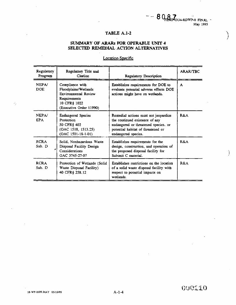
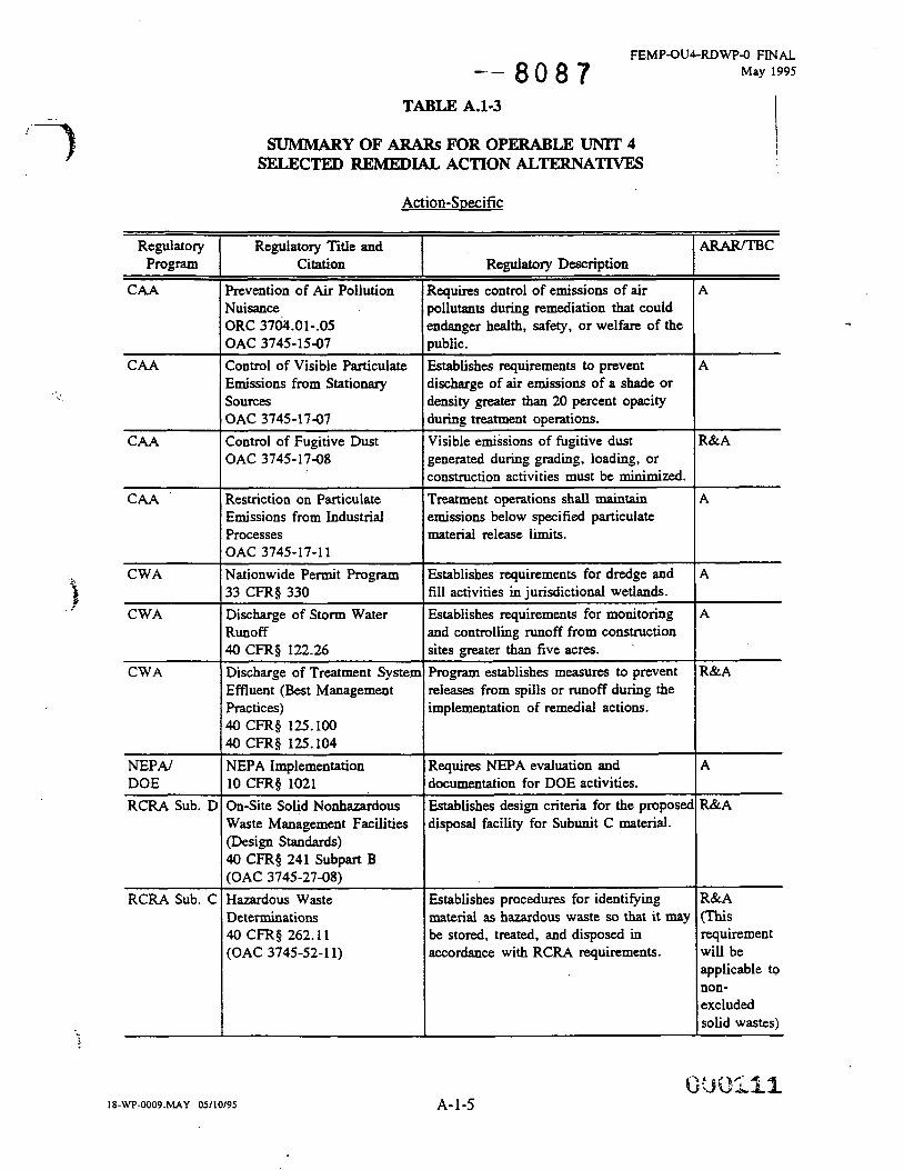
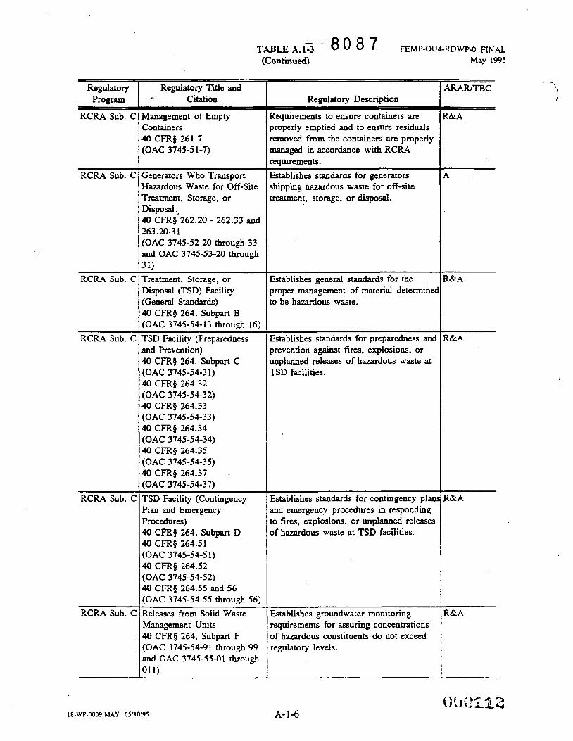
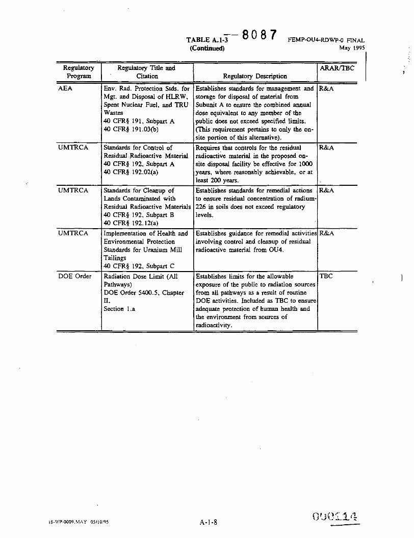
Provides a summary of the applicable or relevant and appropriate requirements (ARARs) and to-be-
considered (TBCs) pertinent to the Operable Unit 4 remedial design.
1
18-W-OOO9.MAY 05/12/95 1-3
18-UT-0009.hlAY OS/ 1 2/95
- 4 0 8 7
This Page Intentionally Left Blank
\
i
I
= - a 0 8 7
SECTION 2.0
BACKGROUND
This Page Intentionally Left Blank
18-WP-0009. hIAY 0511 2/95
- - 8 0 8 7 ! -.
!
-- 8 0 8 7
FEMP-OUCRDW-O FINAL May 1995
2.0 BACKGROUND
This section summarizes the background information concerning the FEMP and Operable Unit 4 relevant
to this work plan. Included in this section is a brief summary of the site location, description, and history
(Section 2. l), current site status (Section 2.2), and an overview of the nature and extent of contamination
(Section 2.3).
2.1
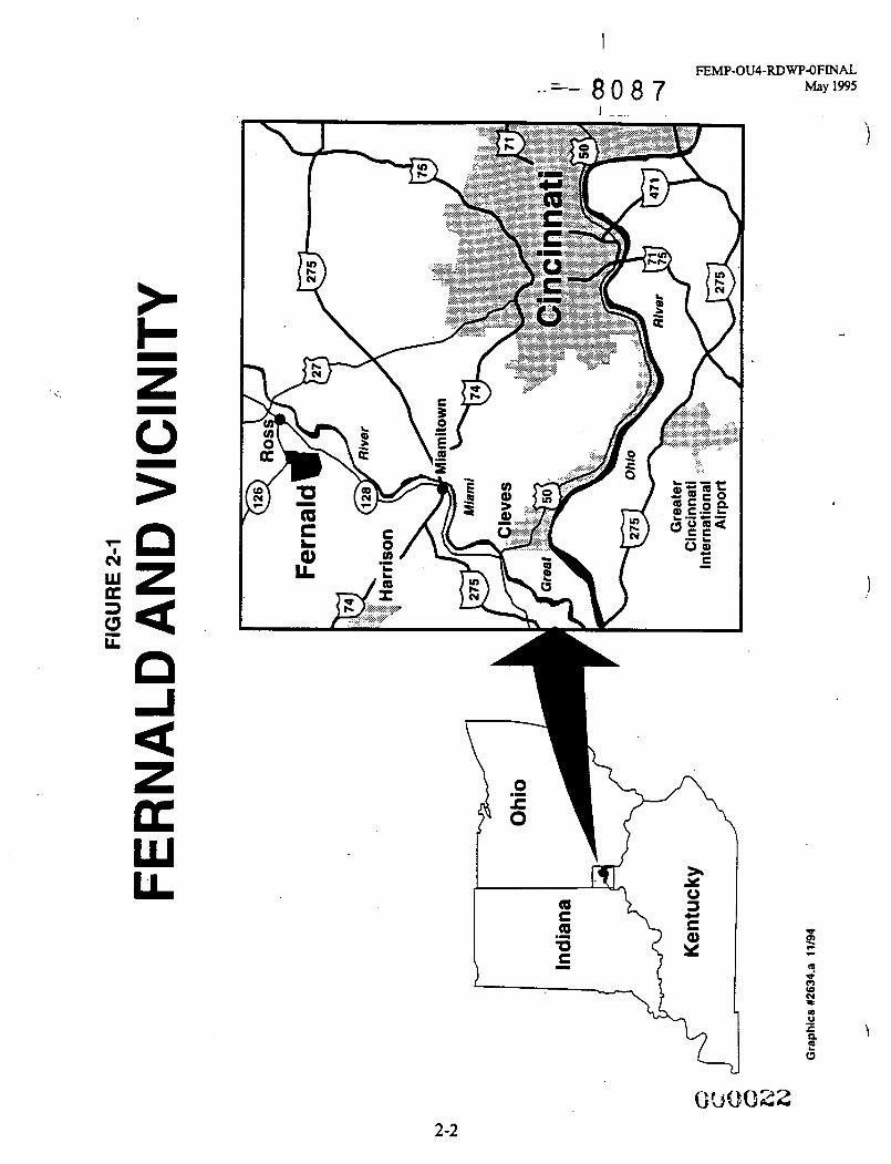
The F E W site is a 425 hectare (1050 acre) facility located just north of Fernald, Ohio, a small farming
community, and lies on the boundary between Hamilton and Butler Counties. Ofthe total site area, 345
hectares (850 acres) are in Crosby Township of Hamilton County, and 80 hectares (200 acres) are in Ross
and Morgan Townships of Butler County. Other nearby communities include Shandon, New Baltimore,
Ross, and Harrison (see Figure 2-1). Production operations at the facility were limited to a fenced 55-
hectare (136-acre) tract of land, now known as the former Production Area, located near the center of
the site. The FEMP's primary mission was to process uranium into metallic "feed" materials for other
DOE facilities for use in the nation's defense program.
Site Location. Descriution. and Historv
5
Prior to 1984, solid and slurried materials from uranium processing were stored or disposed in the on-site
Waste Storage Area, which is located west of the former Production Area. Operable Unit 4, on which
this phase of the FEMP remediation is focused, is situated in the southwestern portion of the Waste
Storage Area, occupying an area of approximately 2 hectares (5 acres) (see Figure 2-2). Operable Unit 4
consists of two earthen-bermed, concrete silos containing K-65 residues; a decant sump tank; one silo
containing cold metal oxides; one unused silo; and various quantities of contaminated soils and debris.
Briefly stated, the Operable Unit 4 site history dates back to the early 1950s, when the silos were
constructed and received residues for storage. These residues were generated from the process of
extracting uranium from high grade uranium ores and concentrates in support of the United States defense
programs. These residues are classified as by-product materials, consistent with Section 1 l(e)2 of the
Atomic Energy Act (AEA). Facilities and equipment associated with this placement, storage, and
continued maintenance of these materials include: a decant sump tank, radon treatment system (RTS), various concrete pads, and miscellaneous piping and appurtenances. In 1991, a bentonite clay layer was
added over the residues in Silos 1 and 2 to reduce chronic radon emanation from both silos. In addition,
an Expedited Removal Acrion was completed in January 1992, when an out-of-service dust collector and
hopper assembly were removed from the dome oi Silo 3. Minor facility modifications (Le., equipment
upgrades) have also been made in recent yeacs to enhance radon monitoring capabilities, storm water
runoff controls, and decant sump tank maintenance activities.
2.2 Current Site Status
In July 1986, the DOE and EPA signed a Federal Facilities Compliance Agreement (FFCA), iddressing
impacts to the environment associated with federally operated sites (including the FEMP). The DOE
agreed to conduct the FFCA investigation as a Remedial InvestigatiodFeasibility Study (RI/FS) in
accordance with guidelines of CERCLA. In November 1989, the FEMP site was included on the
National Priorities List (NPL) of the EPA. The FFCA was later amended by the June 1990 Consent
Agreement between DOE and EPA which was furthtr modified by amendment in September 199 1 .
In accordance with the Amended Consent Agreement :.September 1991), the DOE submitted to EPA a
Draft Remedial Investigation (RI) Report for Operable Unit 4 in April 1993, which was later submitted
as a Draft Final and Finz: 2eport in August 1993, and November 1993, respectively. Final approval of
the Final RI Report for Gperable Unit 4 was received in August 1994. Likewise, a Draft Feasibility
Study (FS) Report and Proposed Plan (PP) for Remedial Actions at Operable Unit 4 were submitted to
the EPA in September 1993. Subsequent Draft Final and Final documents were submitted to the agency
in December 1993, and February 1994, respectively. Final EPA approval of the Final FS Report and
PP for Operable Unit 4 was received on August 1994.
The Final ROD for Remedial Actions at Operable Unit 4 was submitted to the EPA in November 1994.
The EPA approved and signed the Final ROD for Remeaial Actions at Operable Unit 4 on December 7,
1994.
Currently, a pilot plant trs::3ility study progrm IS being conducted. The primary goals of this program
are to provide essential data needed for detailed remedial design in areas of waste retrieval, full-scale
vitrification process scale-up, optimal mixdesign parameters, off-gas treatment, and vitrified product
18-WP-OOO9.MAY 05112195 2-4
I
a FEMP-OU4-RDWP-0 FINAL May 1995
handling. Additional details regarding the integral relationship of the Pilot Plant Phases I and I1 Treatability Study Program and the remedial design will be provided in Sections 3.0 and 4.0 of this work
plan.
2.3
This section summarizes .the nature and extent of contamination in environmental media within the
Operable Unit 4 boundary. Also included in this section is an overview of the levels of direct radiation
associated with the current conditions within Operable Unit 4. Additional detail on these conditions is
provided in Section 4.0 of the Final RI Report for Operable Unit 4, November 1993 (1993b).
Nature and Extent of Contamination
i'.
2.3.1 Surface Soils
Sampling performed as part of the Operable Unit 4 RVFS and other FEMP site programs in the vicinity
of Operable Unit 4 indicates above background concentrations of uranium, and to a lesser degree other
radionuclides, in the surface soils within and adjacent to Operable Unit 4. Activity concentrations
observed during the RI for the surface soils in the vicinity of Operable Unit 4 were as much as 20.8
picocuries per gram @Ci/g) for uranium (U)-238, or 16 times natural background (1.22 pCi/g), and 4.8
pCi/g for thorium (Th)-230, or approximately two times natural background (1.97 pCi/g). These above
background concentrations appear to be generally limited to the upper six inches of soil. The Final RI Report for Operable Unit 4 indicates no direct relationship between the surface soil contamination in
Operable Unit 4 and the silo contents. Further, more than 70 percent of the surface soil samples indicate
that the uranium contamination in surface soils is depleted uranium (Le., the uranium contains c0.71
percent of U-235). This result is inconsistent with the silo residues that consist of natural uranium.
Thus, the existence of these activity concentrations in the surface soils are attributed to air deposition
from the former Production Area, past plant production operations, and/or waste handling practices in
the waste pit area.
Soil samples were also collected during the RI for Operable Unit 4 from the soils contained in the earthen
embankment (berm) surrounding Silos 1 and 2. The analytical data from the berm fill show only slightly
elevated radionuclide activity concentrations. Uranium was the predominant contaminant with activity
concentrations less than 4 pCi/g, or approximately three times background (1.22 pCi/g). In addition to
I ?
18-WP-OOO9.MAY 05112195
" - 8 0 8 7 I I
FEMP-OU4RDW-O FINAL May 1995
U-238, activity concentrations of polonium (Po)-210 and lead (Pb)-210 ranging up to 10 and 6 times
background (1.33 pC. These
radionuclides are producai from me natural radioacwe decay of radon (Rn)-222. Their presence in the
berm fill is a direct result of radon escaping the silos by passing through cracks in the silo wall. Once
outside the silo and in the soil, the radon decays to Pb-210 and then Po-210.
and 1.33 pC' 2), resprxvely, were idemified in the berm fill.
,
One sample collected as part of the berm investigations was retrieved from an interval that closely
reflected the original ground surface prior to berm installation. Analytical results from this sample
showed distinctly higher concentrations of radionuclides than other samples taken within the berm soils.
Uranium and radium (Ra) concentrations in the sample were 19 and 580 times background (1.22 pCi/g
and 1.45 pCi/g), respectively. This sample indicates the possible occurrence of spillage or seepage from
the silo onto the original surface soils adjacent to the silo at the sampling location.
2.3.2 Subsurface Soils
As part of the RI for Q?erable Unit 4, samples were collected from the subsurface soils located under
and adjacent to the K-o5 silos. Analytical results reveal elevated concentrations of radionuclides from
the uranium decay series in the soils at the interface between the berm and the original ground level.
Elevated concentrations (up to 53 pCi/g for U-238, about 40 times background) were also noted in slant
boreholes, which passed in close proximity to the silo underdrains.
The occurrence of these above background concentrations in soils near the silo underdrains are attributed
to vertical migration of leakage from the silo underdrains or decanting system. Elevated readings at the
interface between the silo berms and the native soils are attributed to historical air deposition or past
spillage from the silos during filling operations in the 1950s, prior to installation of the berms.
2.3.3 Surface Water and Sediment
Extensive sampling was conducted on the sediment and surface water present in Paddys Run and on key
drainage swales leading to Paddys Run, as part of the RI Report for Operable Unit 4 and other site
programs. Results of the surface water sampling indicate the occurrence of above background
concentrations of U-238, up to 1500 times background, in the drainage swales in the vicinity of Silos 1
lS-WP-OOO9.hlAY 05/12/95 2-6
i I - - 8 0 8 7
FEMP-OUCRDW-O FINAL May 1995
through 4. The highest readings were recorded in a drainage ditch, which flows from east to west,
located approximately 76 meters (250 feet) south of Silo 1. The most probable source of the
contamination in Paddys Run and the drainage swales is the resuspension of contaminated particles from
surface soils in Operable Units 4 and 1 boundaries into stormwater.
2.3.4 Groundwater . With the exception of perched groundwater which may be encountered during remedial action,
groundwater within the Great Miami Aquifer underlying the silo area is not within the scope of Operable
Unit 4. Groundwater in the Great Miami Aquifer underlying the entire FEMP site is being addressed
as part of Operable Unit 5. Groundwater occurs not only in the Great Miami Aquifer underlying the
FEMP site, but also in discrete zones of fine-grained sands located in the soils above the lower aquifer.
The water contained in these sand pockets in the clay-rich glacial soils are termed perched water zones.
Samples were collected from slant borings placed adjacent to and under Silos 1 and 2; 1000-series wells
screened in the glacial overburden; 2OOO-series wells screened at the water table in the Great Miami
Aquifer; and 3000-series wells screened at approximately the central part of the Great Miami Aquifer,
just above the clay interbed. I J
Background concentrations of naturally occurring inorganics and radionuclides in groundwater in the
vicinity of FEMP site were being established under the site-wide WFS during the completion of the RI Report for Operable Unit 4. The background concentration of total uranium in groundwater was assumed
to be less than 3 micrograms per liter (pg/P) or 3 parts per billion (ppb).
2.3.5 Perched Water
Uranium was the major radionuclide contaminant found in the perched water. Elevated concentrations
of total uranium were detected in the slant boreholes under and around Silos 1 and 2. Slant Boring 1617,
immediately southwest of Silo 1, contained the highest concentration of total uranium (9240 pg/4).
Uranium concentrations were also elevated in samples collected from the 1OOO-series wells. The highest
observed total uranium concentrations obtained from 1000-series wells were in samples collected from
Well No. 1032, located 46 meters (150 feet) due west of Silo 2. .The range of the concentrations was
18-WP-OOO9.hfAY 05.11 3/95 2-7
- - - 8 0 8 7 I .
FEMP-OUCRDWP-O FINAL May 1995
196 to 276 pglt. Considering both the slant borings and 1000-series wells, U-238 was found in the range
of 1.1 to 1313 pCilt . . .
The major inorganic constituents found in the perched water samples, taken from 1000-series wells and
the slant borings, included elevated concentrations for major cations (iron, magnesium, manganese, and
sodium) and major anions (chloride, nitrate, and sulfate). In particular, the concentrations of sodium,
sulfate, and nitrate were significantly above background in slant boring samples. Boring 1615, northwest
of Silo 2, had the highest sodium concentration [1,040 milligrams per liter (mg/t)], boring 1618,
southeast of Silo 1, had the highest sulfate concentration (2,200 mgl!), and boring 1617 had the highest
nitrate concentration (554 mglt). Low concentrations of organic constituents were detected in some
samples. Overall, well measurements and analytical results confirmed that the perched groundwater in
the vicinity of Operable Unit 4 flows from east to west.
2.3.6 Great Miami Aauifer
The concentration of total uranium in the upper portion of the Great Miami Aquifer, based on analysis
of samples from the 2000-series wells, ranged from less than 1 pglt to 40.3 pglt. These data do not
necessarily suggest that the silos are the source of the observed contamination because both upgradient
and downgradient wells contain above background concentrations of total uranium. Well No. 2032,
located 46 meters (150 feet) west of Silos 1 and 2, exhibited a concentration of total uranium at 39.0
pglt. Well No. 2033, located 46 meters (150 feet) east of Silos 1 and 2, exhibited a concentration of
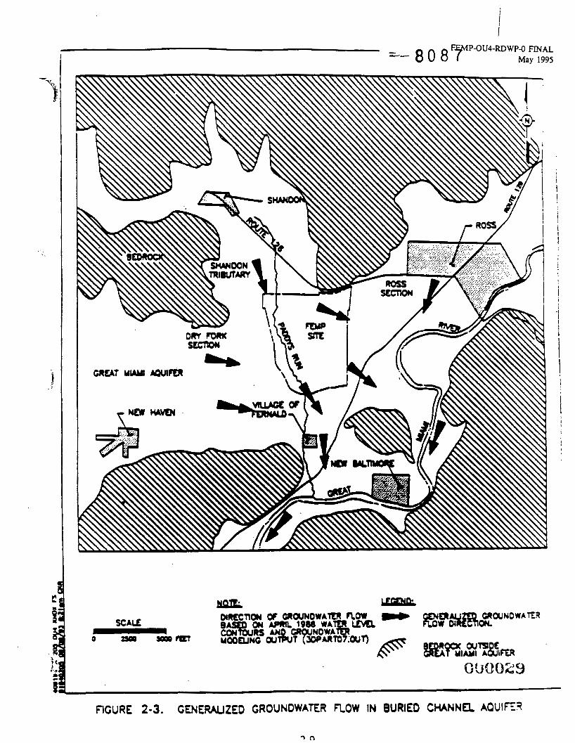
total uranium at 40.3 pglC. Because groundwater flow in this region of the Great Miami Aquifer is from
west to east (see Figure 2-3), these two wells are located upgradient and downgradient of Operable Unit
4, respectively.
The isotopic ratio of U-234 and U-238 would suggest the uranium in these samples is from a natural
source. Such a ratio may be expected from Operable Unit 4, but is not a "fingerprint" for this source.
The presence of uranium upgradient in the aquifer from an Operable Unit 4 sourcc could be explained
by leachate travel in the perched groundwater zone of the glacial overburaen with emergence to Paddys
Run. Here the diluted leachate could enter the aquifer via stream bed infiltration or flow at the perched
zonelstream channel interface. No evidence is available to support or preclude this potential route.
i
18-WP-0009. M A Y 05I 12195 2-8
i !
! i I
1 I
i 1
i !
I
! i
I
FIGURE 2-3. CENERAUZED CROUNOWAER FLOW IN BURIED CHANNa AOUIE?
FEMP-OUCRDWPO FINAL May 1995
The concentration of total uranium measured at deeper levels in the Great Miami Aquifer (3000-series
wells) ranged from less than 1 to 4 pgl l , with the exception of 1 sample out of 16, which contained 15
pg/ t . Like the 2000-series wells, no conclusion could be drawn to link or not to link this contamination to the silos.
18-WP-0009. MAY 051 12/95 2-10
SECTION 3.0
REMEDIAL DESIGN OBJECTIVES, SCOPE
AND STRATEGY
i
- - a 0 8 7
j = - 8 0 8 ?
This Page Intentionally Left Blank i
I8-U’P-O009.%UY OSil29.5
FEMPaU4-RDWP-0 FINAL May 1995
3.0 REMEDIAL DESIGN OBJECTIVES. SCOPE AND STRATEGY P
3.1 Objectives
The purpose of the RD is to develop final construction plans, specifications, and bid documents, in
accordance with CERCLA time-frame requirements for the selected remedy in the ROD for Remedial
Actions of Operable Unit 4, approved and signed by the EPA on December 7, 1994. The overall
objectives of the Operable Unit 4 remedial actions are to safely remove a known source of contamination
to reduce the potential for release of hazardous substances, including radionuclides, to the environment
in such quantities that could present an unacceptable risk to human health and the environment. The
remedial design efforts have been structured to ensure that substantial, physical and continuous remedial
activities can be initiated and sustained by March 3, 1996.
3.2 ScoDe
Under the selected remedy, the K-65 residues and cold metal oxides will be removed from Silos I, 2,
and 3 and treated in a newly constructed on-property vitrification plant. The sludges from the decant
sump tank will also be removed and treated in the vitrification facility. Following treatment, the vitrified
residues will be containerized and transported off site for disposal at the Nevada Test Site (NTS).
Following removal of the residues, the concrete silo structures will be dismantled. Additionally, the
decant sump tank system. the existing radon treatment system and other miscellaneous structures within
the Operable Unit 4 area will be demolished and dispositioned consistent with the ROD for Operable Unit
3. Following completion of treatment, the vitrification plant will be disassembled and decontaminated
to the extent practicable. Opportunities for recycling or reuse of materials will also be explored to
minimize waste generation.
Contaminated soils within the boundary of Operable Unit 4 will be excavated to the extent necessary to
attain the remediation levels defined by the Operable Unit 4 (see Tables 3-1 and 3-2) and Operable Unit
5 RODS. Excavated areas would be backfilled to original grade and revegetated. Any perched water
encountered during remediation will be collected and sent to the FEMP Advanced Waste Water Treatment
(AWWT) facility for treatment prior to discharge to the Great Miami River.
jf I 8 -WP-0009. MAY OS/ 1 2/9S 3- 1
N
0 0 1 - V
a z
09 0
I -. FEMP-OW-RDWP-O FINAL
= - 8 0 8 7 May 1
3-2
c
I FEMP-OW-RDWP-O FINAL
8 0 8 7 May 1995
\J
J-J
F
3-4
-9 FEMP-OU4-RDWp-0 FINAL May 1995
Contaminated soil and debris will either be processed and/or disposed in accordance with the selected
Operable Unit 5 and Operable Unit 3 remedies, or placed in an interim storage facility, at a suitable
location at the site, to await the finalization of the disposal decisions for soils and debris under Operable
Unit 5 and Operable Unit 3. The interim storage will be managed pursuant to the approved work plan
for Removal Action 17 (Improved Storage of Soil and Debris).
3.3 Remedial Design ADDroach
Remedial Management Strategy
There are several regulatory requirements that directly influence the approach developed by the DOE in
structuring the remedial management strategy for Operable Unit 4. The CERCLA, Section 120(e)(2)
states that, ..." substantial continuous physical on-site remedial action shall be commenced at each facility
not later than 15 months after completion of the [remedial] investigation and [feasibility] study." EPA
considers final approval of the ROD as signifying the completion of the remedial investigation and
feasibility study phase of the project. For Operable Unit 4, the 15-month criteria milestone has been
determined to be March 3, 1996.
In order for remedial activities to be considered (by the €PA) to satisfy the intent of "substantial" and
"physical" requirements of Section 120(e)(2), remedial activities must represent a significant step in the
process, and be a part of a logical and reasonable plan. Since the requirements apply to each Record of
Decision at the FEMP, determining whether specific activities satisfy the test is an operable unit-specific
issue. With respect to Operable Unit 4, the EPA has agreed that the beginning of construction of the
Operable Unit 4 treatment facilities (including site preparation and utilities installation to support the
treatment facilities) would constitute a substantial and physical activity, since construction of these
facilities is necessary before treatment of the silo residues can begin (EPA 1994).
Section 120(e)(:?) of CERCLA also requires the continuous implementation of remedial activities, which
is defined by the EPA to mean that within 15 months of the ROD approval date there must be a tangible
commitment to implement the remedy. Usually, the mechanism by which the EPA recognizes the
demonstration of such a commitment is the entry into a legally binding contract for remedial services. 1
I 8 -W P-OOO9. M A Y OS! 1 2!9S 3 -5 e00037
\
- - 8 0 8 7
Consequently, one way the DOE will demonstrate compliance with the Section 120(e)(2) "continuous"
requirement will be to award, within 15 months of the ROD approval date, contract(s) for activities
included in the approved Operable Unit 4 RD Work Plan.
The EPA has also recogwed that DOE'S contracting activities must comply with federal procurement
requirements and the Anti-Deficiency Act. It is the opinion of the €PA that at a minimum, Section
120(e)(2) of CERCLA requires that contracts for remedial activities, which are scheduled for the fiscal
year in which such activities are required to begin, will be in place within 15 months of the ROD
approval date. The EPA requires that if DOE cannot, within 15 months of the ROD approval date,
award contracts for Operable Unit 4 remedial activities which are scheduled for subsequent fiscal years,
DOE must include in its RD Work Plan schedule those activities necessary to award all contracts
including making requests to Congress for funding (EPA 1994). Once the RD Work Plan is approved,
the deliverables and milestones identified in the work plan schedule will be enforceable by the €PA
pursuant to Section XVII of the Consent Agreement, as amended under CERCLA Sections 120 and
106(a), Docket Number V-W-90-C-057 (1991).
Further, Section X1.A of the Amended Consent Agreement requires that the DOE, within sixty (60) days
of the approved ROD for Operable Unit 4, submit to the EPA for approval the work plan by which the
design for remedial action will be accomplished. In addition to these requirements, the EPA has published guidance documents that delineate the requirements for properly conducting remedial design
and remedial action activities under EPA oversight. These guidance documents (EPA 1986, EPA 1990a),
which were developed to assist the EPA (as the lead agency) in its management and oversight of
CERCLA remediation activities in the public domain, have been incorporated to the extent practicable.
Consistent with these aforementioned requirements, the DOE has adopted a remedial management strategy
specific for Operable Unit 4 which not only satisfies these requirements. but expedites to the extent
practicable the Operable Unit 4 remedial design and remedial action process. The proposed approach.
outlined by this work plan. allows the Operable Unit 4 remedial design and remedial actions to be divided
into logical, and manageable work elements (e.g., phases, design packages, etc.) to accelerate their
implementation. In addition, the proposed succession of remedial activities is part of a sound, reasonable
,!
I8-WP-OOO9.MAY O S l l l i 9 S 3-6
FEMP-OUCRDWP-O FINAL May 1995
plan that is comprised of substantial and physical activities which satisfy the intent of Section 120(e)(2)
of CERCLA.
Phased Desim Amroach Summary
The remedial management strategy for Operable Unit.4 utilizes a phased approach to accomplish the
remedial design and remedial action activities. This method allows the various regulatory, technical, and
financial constraints to be addressed by the project. The phased design approach consists of a series of
logically planned remedial design packages and submittals. One of the integral parts of this approach is
the manner in which the Pilot Plant Phases I and I1 Treatability Study Program is integrated directly into
the remedial design schedule effort for the Vitrification Plant. The Operable Unit 4 remedial design
process will be performed in two distinct phases of work as follows:
-*
a Silo Residue Retrievalflreatment Facility Remedial Design
a Final Site Remedial Design
The successful implementation of this logical sequence of remediation design phases and their subsequent
design packages, will facilitate compiiance with the intent of CERCLA Section 120(e)(2) requirements
for initiating substantial continuous physical remedial activities. In addition, it minimizes the schedule
risks associated with che project's technical design, which is dependent on the ongoing Pilot Plant Phases
I and I1 Treatability Study Program, and takes into account inherent contracting constraints imposed by
the annual federal budgetary process. Similarly, since the Operable Unit 4 final site remedial design will
be greatly influenced by the approved RODS for Operable Units 3 and 5 , this phased approach affords
the Operable Unit 4 remedial design the benefit of utilizing the most current decision-making information
developed by those operable units.
Pilot Plant Phases I and I1 Treatabilitv Studv Promim Interface
One of the key project elements which will have a direct influence in determining the overall success of
the Operable Unit 4 remediation efforts is the timely integration 'of design information generated from
the Pilot Plant Phases 1 and I1 Treatability Study Program into the Operable Unit 4 remedial design. This
integration is graphically depicted on the schedule presented in Figure 5 3 . The main advantage provided ...
I 8 -WP-0009.hlAY os11 119s 3-7
- - a 0 8 7 I
FEMP-OU4-RDWP-O FINAL May 1995
by the scheduling of the Pilot Plant Phases I and I1 Treztability Study Program is that it permits adequate
time for the collecion of quantitative performance L x on the innovative application of the vitrification
treatment technology to the Operable Unit 4 residues. While already completed RYFS treatability bench-
scale testing has yielded promising results, this iecchnology lacks sufficient full-scale application
experience involving this wastestream (or similar wastestreams) to be routinely considered for full-scale
remediation without extensive pilot scale treatability testing.
The demonstration of the vitrification process is essential in order to establish design data necessary for
scale-up of processes and equipment to full-scale capacity. Upon completion of the Pilot Plant Phases
I and 11 Treatability Study Program, the results will be incorporated into the ongoing Preliminary (30%)
design (Title I) effort and allow initiation of the detailed design effort vitle 11). Therefore, the Pilot
Plant Treatability Study Program schedule reflects a "finish-to-start" relationship with the vitrification
plant remedial design. This approach facilitates the evaluation of the necessary detailed design, cost and
performance data necessary to optimize critical parameters of the Vitrification Plant.
The schedule contained in this Final Remedial Design Work Plan for the Vitrification Plant for Operable
Unit 4 calls for four months of Title I work after issue of the final report on Pilot Plant operations (see
Figure 5-4). The schedule also indicates that Title I design of the vitrification plant may proceed well
in advance of the final report issuance, based on best available information and assumptions from Pilot
Plant Phase I operations.
There are several technical issues now apparent which DOE anticipates may require significant revision
and/or new work for the full-scale vitrification plant based directly on Pilot Plant results. These issues
include the following:
0 0 0
0
Melter processing rate and performance Product forming equipment reliability and maintainability Performance of off-gas treatment equipment Worker radiation exposure during operation and. maintenance of the pilot plant
These issues are discussed in detail below.
18-WP-0009.hlAY 0511 2 . 3 5 3-8
FEMP-OUCRDWP-0 FINAL May 1995
Melter
There is little or no experience either in the DOEcomplex or in commercial industry with radioactive
waste vitrification at the anticipated full-scale production rate, with this or any other feed composition.
Also, vitrification performance and capacity are difficult to predict even with similar feed and equipment.
The Pilot Plant operations will determine the maximum extent to which the melter can be scaled-up with
available technology. The Pilot Plant performance will determine the maximum capacity of a single
melter and may dictate whether the required number of melters must increase in order to achieve the
desired throughput. Pilot scale results may also indicate the need for a different glass formulations than
currently anticipated (more or different additives for acceptable glass properties). Indicated design
developments in the glassmaking process will have to be incorporated into the process flow diagrams,
the material balance, and piping and instrumentation drawings (P&IDs) before further final remediation
design can proceed.
Product Formine EauiDment
One of the goals of the Pilot Plant Treatability Study Program is the assessment of the reliability and
maintainability of the product forming equipment under continuous operations. The Pilot Plant
incorporates a gem maker for determining its practicality for full-scale application (a monolith product
form will also be tested). Existing gem makers are known to be high maintenance items. Some require
daily maintenance to support one- or two-shift commercial glassmaking operations. Also, existing gem
makers are designed to handle glass at temperatures around 1100°C (2000°F) rather than the 1250°C to
1350°C (2250°F to 2450°F) planned from the Pilot Plant melter. The Pilot Plant operating results are
very likely to dictate redesign of full-scale systems for improved reliability and maintainability. In
addition, redesign might be necessary due to both throughput requirements and radiation worker exposure
limits.
!
Off-Gas Treatment
The actual removal efficiency of acid gases (e.g. SO,, NO,) and radon may vary from the design; the
Pilot Plant will provide invaluable data in this area. Any changes in sizing, or selection of off-gas
treatment equipment (e.g. scrubbers, desiccants, etc.), will require some time to implement through the
18-WP-0009.hlAY 05/1?195 3-9
5-8087
FEMP-OU4-RDW-0 FINAL May 1995
process and mechanical designs. The effective containment of radon by the process system and treatment
by the carbon bed system will also be paramount.
Radiation ExDosure
Actual radiation exposure measurements of personnel during Phase II pilot plant operations and
maintenance could greatly affect design of the vitrification plant. If the gem maker indeed requires a
great deal of maintenance, such measures as a radiologically controlled maintenance corridor or semi-
remote maintenance may have to be considered. These issues would require additional evaluation and
rework of the designs for the gem maker, and/or melter, and perhaps even the vitrification plant building.
The schedule presented in this Final Remedial Design Work Plan would allow at least some of the time
required for such a redesign.
Therefore. initiating remedial design on the vitrification plant without the benefit of compieting the Pilot
Plant Treatability Study Program is not expedient. The development and demonstration of the technology
by the Pilot Plant Phases I and I1 Treatability Study Program reduces the technical, schedule and
economic risks of the Operable Unit 4 remediation program.
The scope of each of the remedial design phases and various activities required to accomplish the tasks
is described in greater detail in Sections 4.0 and 5.0.
18-wp-0009. htAY os/ 1 3!9S 3-10
t
- - 8 0 8 7
SECTION 4.0
TASK PLAN FOR REMEDIAL DESIGN
...
This Page Intentionally Left Blank
i8-WP-O009..MAY 05112:95
FEMP-0UCRDWP-O FINAL May 1995
4.0
The selected remedy in the ROD for Operable Unit 4 will serve as the basis for performing the remedial
design and will subsequently be implemented during remedial action. The following tasks constitute the
work elements to be performed by DOE during the remedial design €or the remediation of Operable
Unit 4. The modified task numbering system used a this work plan is similar to recommended task
designations for RD as specified by the EPA Office of Solid Waste and Emergency Response. The
following tasks are included in the Operable Unit 4 remedial design:
0 Task 5: Title 1/11 Design - Final Site Remediation
4.1
Task 1 of the remedial design will focus on the development of drawings, specifications and project
planning documentation necessary to perform the safe removal and treatment of the silo residues. Task
1 is currently being conducted and includes the following activities:
Task 1. Title I Design - Proiect Plannine Documentation
.
0 .
0 Preparation of Remedial Design Work Plan . 0 0
Review of Existing Data
Preparation of Title I Documentation Title 1/11 Design Data Needs/Support Studies
18-WP-0009.hi~Y 05/12/95 4- 1
- - 8 0 8 7 1 FEMP-OU4-Ww-0 FINAL
May 1995
4.1.1 Review of Existing Data
Various types of data are available from the remedial investigation; several treatability studies and the
feasibility study activities that were performed for the EPA as agreed to in the Amended Consent
Agreement. Three key documents for use in this RD are: the Final Remedial Investigation Report for
Operable Unit 4, November 1993; the Final Feasibility Study Report for Operable Unit 4, February 1994;
and the Final Record of. Decision for Remedial Actions at Operable Unit 4, December 1994. The
information contained within these documents will be reviewed and evaluated to ensure that all relevant
predesign data, including all applicable or relevant and appropriate requirements (ARARs), will be
incorporated into the design effort.
In addition, all available data and “lessons-learned’‘ generated from the construction, start-up, and
operations of the Phases I and I1 Pilot Plant Treatability Study program will be incorporated into the
remedial design effort.
4.1.2
This activity consists of the preparation of this RD Work Plan. Draft and Final versions were submitted
in accordance with the project schedule (see Section 5.2). Consistent with previous Consent Agreement
document submittals. it is assumed that both €PA and OEPA comments on the Final RD Work Plan will
be formally submitted to DOE.
PreDaration of Remedial Design Work Plan
4.1.3
The main objective of this subtask will be to establish a design basis, and freeze the project scope and
baseline features for project management purposes. The project planning documentation developed under
Preoaration of Title I Desim Proiect Planning Documentation
this subtask will serve as the technical baseline for all Title VII remedial design efforts.
Functional Reauirements Document ffRD]
The FRD will identify and define functional requirements for the remedial design in terms of the
functions that the various systems must be capable of performing, a d the constraints and limitations that
the design must satisfy. The functional requirements do not address detailed design requirements but
rather establish the baseline for the development of Title I and Title I1 Design. This baseline information
i
18-UP-OOO9.hL4Y 05:12195 4-2
i
e- 8 0 8 7
FEMP-OU4-RDWP-O FINAL May 1995
allows tracking of the final detailed system requirements back to their origin (functionally) for the future
assessment of design with respect to the original goals, objectives, and requirements.
Design Criteria Packape
The Design Criteria Package @CP) includes engineering design criteria and the project design basis.
The DCP will present ttie engineering design criteria in accordance with DOE Order 4700.1. The
objective of the engineering design criteria is to identify and specify all the applicable general and
discipline-specific design requirements that must be satisfied in perforking the engineering design, and
preparing construction drawings and specifications for the final remediation. The DCP will list all
pertinent DOE Orders, AMRs and "to be considered" (Tl3C) requirements, Engineering Design Codes
(national. state, and local) and Standards, as well as describe how the project design will satisfy
-
,.
compliance with the A M & , TBCs, and pertinent DOE Orders identified for this project.
The DCP will also address the project design basis. This discussion will provide a complete narration
of the remediation facility functional systems along with any known design constraints and limitations.
In addition, a list of the assumptions to be used in the preparation of the design will be presented. As
the remedial design effort progresses through its preliminary stages toward final design, the assumptions
will be periodically evaluated for confirmation and updated as necessary.
i.
4.1.4
As identified in the list of assumptions and information needs discussions presented in the DCP, several
activities must be completed (e.g., Pilot Plant Treatability Studies, Engineering Studies, etc.) to provide
key information for design and operational requirements. The following section describes these activities.
Title 1/11 - Design Data Needs/Sumort Studies
4.1.4.1
The Operable Unit 4 Remedial DesigdRemedial Action (RD/RA) Treatability Study Program consists
of the removal and processing of K-65, bentonite clay, and Silo 3 material. The Treatability Study
Program is being conducted in two phases as delineated in the "Operable Unit 4 Pilot Plant Phases I and
I1 Treatability Study Work Plans." The following is a summary of the work that is being accomplished
in support of the Operable Unit 4 RD.
Pilot Plant Phases I and I1 Treatabilitv Studv Program
18-WP-OOO9.MAY 05112195 ' 4-3
FEMP-OU4-RDWP-0 FINAL May 1995
The Pilot Plmt Phase I Treatability Study Program will verify the adequacy of the equipment, process,
and methodology of waste retrieval and the vitrification plant. The following is a list of the activities
included in the scope of Pilot Plant Phase I operations:
0 0 0
Superstructure and Equipment Room Construction Pilot scale vitrification plant construction Continuous operation of the vitrification plant with surrogate, non-radioactive materials
The Title I design documentation (ie. DCP) for the Vitrification Plant will be updated and finalized by
incorporating any design and operational changes resulting from the data and the lessons-learned from
the Pilot Plant Phases I and I1 Treatability Study Program.
Phase I1 of pilot scale testing will require minimal modifications to the vitrification plant constructed for
Phase I. All "lessons learned" in Phase I concerning process control, equipment operation, material
handling, and mix design will be incorporated into the Phase I1 operations. Phase 11 testing will utilize
actual K-65 and Silo 3 material. K-65 material will be removed with a manuallyaperated slurry pumping
device suspended from a mobile crane over Silo 2. This device will be deployed through an existing
rnanway using a bag-in bag-out method to maintain the silo in a sealed condition. In addition to actual
K-65 and Silo 3 vitrification, Phase I1 will demonstrate pneumatic removal of Silo 3 material, radon
control for Silos 1 or 2 headspace atmosphere, and off-gas treatment for the vitrification plant. The
following major activities are included in the work scope of Phase I1 Pilot Plant operations:
0 0 0 0 0 0 0 0 0 0
K-65 Silo Radon Treatment System (RTS) upgrade (valves and ducting) Vitrification plant modification (if required) K-65 hydraulic material retrieval Silo 3 pneumatic material retrieval Vitrification of K-65 and Silo 3 material Gem making Vitrification furnace off-gas treatment Final product handling Safe Operation Philosophy Data Collection Methodology
4-4
a - - 8 0 8 7 1
FEMP-OU4-RDW-0 FINAL May 1995
Information obtained from the Pilot Plant Phases I and I1 Treatability Study Program will be used to
generate quantitative performance data, and to further refine the remedial design of the final vitrification
plant and the cost estimate for full-scale remediation in the following areas:
1) 2) 3)
Determine limitations of the vitrification technology during continuous operation. Process design parameters for all process unit operations. D e t e b e scale-up factors (parameters) needed for full-scale production plant design.
Full-scale remedial design will focus on hydraulic waste removal and vitrification treatment for K-65 material, and pneumatic waste removal and vitrification treatment for Silo 3 material. The design of the
final treatment facility will take advantage of all "lessons-learned" from the Pilot Plant Treatability Study
program.
4.1.4.2 Reauired Technical Studies
Several areas of the project have been identified that require additional engineering studies and evaluation
before their associated detailed remedial design are initiated. The areas identified will include, but not
4.2 Task 2. Title In1 Desim - Remedial Facilities Infrastructure
4.2.1
Title 1/11 of the remedial design will focus on the development of drawings, spe
PreDaration of Title 1/11 Design
FEMP-OU4-RDWP-O FINAL May 1995
ifi
- Date
August 15, 1995
August 15, 1995
December 4, 1996
ations and engineering
support documentation necessary to perform the safe removal, treatment and disposal of the silo residues.
Title I Design
In general. Title I engineering and design will be performed to produce Process Flow Diagrams (PFDs), Piping and Instrumentation Diagrams (P&IDs), General Arrangement Drawings (GAS), Site Plan,
Selected Equipment Performance Specifications, Equipment Lists, Control Philosophy, Electrical Single
Line Diagrams, and Preliminary Engineering Calculations. PFDs will show process flows and material
balances. P&IDs will show, in addition to process flow, all the equipment with their tag numbers,
control logic, and instrumentation. Based on the PFDs and P&IDs, the GAS will be prepared and
sufficiently detailed to show the relative arrangements of all the major equipment, structures, building,
major pipe racks, etc., in plan and section.
Procurement Documents
Based on the specific requirements of each remedial design package, a procurement strategy will be
developed which will effectively utilize " fixed-price subcontracting" and/or "request for proposal"
procurement packages. As the remedial design effort unfolds, bid documents will be developed
commensurate with the remedial design progression. A discussion of the level of detail presented in each
design package submittal is presented in Section 5.3.
1 8-WP-0009. M A Y 05: I 2/93 4-6
FEMP-OU4-RDWP-0 FI?:.U May 1995
Identifv Lone-Lead Procurement Items
This activity involves the identification of procurement items that are expected to take significant time
to obtain and that may impact the project's construction schedule for completion. Items to be considered
for this category primarily include, but are not limited to, the availability and schedule constraints
associated with the vitrification furnace, gem-forming machine, electrical subsmion, and air monitoring equipment. .-.
x. Construction Schedule
A construction schedule will be developed and refined with the completion of each remedial design
construction package. The schedule will provide a rough estimate of time required to complete the
specific remedial action and will include an identification of the major construction tasks and subtasks.
The target accuracy of the schedule will be logically refined as the design progresses (see Section 5.3 for more details regarding specific submittal information).
Construction Cost Estimate
A cost estimate will be developed and refined for submittal with the pre-final design deliverable. Each
cost estimate will provide an estimate of cost required to construct the specific remedial action and will
include an identification of the major construction tasks and subtasks. The target accuracy of the cost
estimate will be refined as the design progresses (see Section 5.3 for more details regarding specific
B
submittal information).
Title I1 Design
In general, Title I1 remedial design effort will consist of detailed engineering calculations, design
drawings. and specifications required for construction of the remedial facilities. The final specifications
for this project will be prepared using the Construction Specifications Institute format.
4.2.2 Remedial Facilities Infrastructure
In order to achieve the 15-month criteria for initiating substantial physical remedial activities. and to
sustain continuous efforts, the Title I .and I1 remedial design efforts for the following remedial activities
have been combined into three distinct design packages. .. I;
- 4-7 I8-WP-OO09.MAY os11 219s
- 8 0 8 7
FEMP-OUCRDW-O FINAL May 1995
0
0
Title I/II - Underground UtilitiedSite Preparation
Title I/II - Silo Superstructure
Title 1/11 - Radon Treatment System
The main purpose of this approach i$ to logically divide the main detailed design effort into discrete
elements of the remedid treatment facilities, such as the underground utilitiedsite preparation, silo
superstructures, and the Silos 1 and 2 headspace radon treatment system, whose Title VI1 design can be
combined and accelerated independent of the main remedial process facilities in order to sustain
continuous substantial and physical remedial actions in the field (following the site preparation activities),
while the more complex process facil.. 1s complete their design. These components when combined, will
form the infrastructure which will support the primary remedial facilities for Operable Unit 4.
This design package has been specifically scoped and accelerated to satisfy the Section 120(e)(2)
requirements to initiate substantial continuous physical remediation within 15 months of the EPA- approved ROD (March 3, 1996). The elements of this design package will focus on the fundamental
remedial actions which will support the implementation of the selected remedy.
Operable Unit 4 is located in the southwest portion of the Waste Pit Area on the western side of the
FEMP site. The existing utilities in this area are quite limited and insufficient to support the remedial
facilities necessary to implement the Operable Unit 4 selected remedy.
The eastern area adjacent to the Operable Unit 4 boundary, where the remedial process facilities will be
constructed, is relatively underdeveloped and will require site preparation. Site preparation activities
will include. but not be limited to preliminary site grading, the installation of run-ordrunoff controls,
electrical power, fire protection, sanitary and storm sewer lines, process and potable water, etc., to a
convenient termination point to facilitate future connections.
Since the conceptual footprints of the new remedial facilities overlap the K-65 trench area, a portion of
the K-65 trench (concrete pipe trench) originally used to house utilities and original material-transfer
i
!
IS-UP-0009.hUY 05;12:95 4-8
-- 8 0 8 7 1 I
FEMP-OU4-RDWP-O FINAL May 1995
piping used to fill the silos may be removed or filled-in as part of the site preparation activities.
Currently, the trench contains an active airline and potable water supply to the Waste Pit Area. The
demolition of the K-65 trench will be closely coordinated with Operable Units 3 and 5 . All active piping
interfering with the Vitrification Plant will be relocated.
4.2.2.2 Silo SuDerstructures Desim
Silo residues will be removed hydraulically from Silos 1 and 2 and pneumatically from Silo 3. This work
will be accomplished from an enclosed work platform, suspended over each silo dome. The work
platform will be structurally mounted to a steel superstructure which will span each silo. As discussed
in Section 4.1.4, a study will be performed to investigate the possibility of relocating the Silo 4
superstructure (constructed as part of the Pilot Plant Phases I and I1 Treatabiliry Study Program) for re-
use over Silos 1, 2, or 3. If this is not practical, a new superstructure will be designed for the hydraulic
and pneumatic removal operations. The design and construction will be based upon the Silo 4
superstructure design concept to support waste retrieval operations without adversely affecting the
structural integrity of the Silos.
4.2.2.3
In 1991. a removal action was completed during which, a bentonite cap was placed over the contents of
Silos 1 and 2 in effort to attenuate the radon emanation rate from the silos. Immediately following the
removal action. the radon concentration in each silos’ headspace dropped dramatically; however. over
time radon concentrations have gradually increased to approximately 1,OOO,OOO pCi/L and 3,500,000
pCi/L in Silos 1 and- 2 respectively. Once the bentonite caps in each silo are breached during waste
retrieval operations, the attenuation barrier will be compromised and it is anticipated that the silos’ radon
headspace concentrations may increase. A radon treatment system capable of treating both silo’s
headspace to reduce radon concentrations to acceptable levels will be designed and constructed.
Radon Treatment Svstem (Silos 1 and 2) Design
The design of the radon treatment system (RTS) for the Silos 1 and 2 headspace will be based on the
operational data and specific performance measurements to be obtained from the completion of the
onzoing Pilot Plant Phases I and I1 Treatability Study Program. To date, the design of a RTS capable
of treating on a continuous basis large volumes of air containing relatively high concentrations of radon 3
i 8-WP-O009.!4.4Y OS/I 3 9 s 4-9
- 8 0 8 7 1
has never been performed. The final design of the RTS will be based on the performance and design of
previous successful off-gas treatment systems from both the existing silo RTS and the radon treatment
system to be used in the Pilot Plant.
4.2.3
The efforts expended under Task 2 will result in the development and submittal of three design packages
in accordance with the project schedule as follows:
0 Title 1/11 - Radon Treatment System - Pre-final (90%) Review Package
January 2, 1997
Due to their relatively straightforward design, the aforementioned Pre-final (90 W ) del iverables have been
selected by DOE to be submitted to the agencies without first undergoing formal Preliminary (30%)
design review package submittals in order to expedite the remedial design schedule. However. in an
effort to facilitate the ongoing communication of the technical issues and concerns between the parties,
the DOE will informally submit Preliminary (30%) design review packages for informational purposes
only to both agencies, in parallel with its own review.
4.3
The Title 1/11 design of the vitrification plant includes the following design areas:
Task 3. Title 1/11 Design - Vitrification Plant
0
0 Melter/product-forming and handling/off-gas Personnel support/plant buildings and services/process plant
i
IS-WP-0009.MAY 05'I??95 4- 10
FEMP-OUCRDWP-O FINAL May 1995
The following subsections discuss each of the planned remedial design areas.
4.3.1
The Title I and I1 remedial design efforts will focus on the engineering of the remedial process facility,
personnel support, and service buildings. These buildings . . and facilities will form the underlying
foundation to house and support the implementation of the selected remedy. The following is a
conceptual discussion of these facilities.
Personnel SumodPlant Buildings and Services/Process Plant
4
k'.
Personnel S U D D O ~
A facility will be designated to support personnel either operating the remedial process plant and/or
working directly in the Operable Unit 4 final site remediation activities. This facility will functionally
provide change-idchange-out facilities, showers, a break area, and restroom facilities for all personnel.
.
Plant Facilities
This element of the remedial design package is to develop the Title I and I1 design for the various
building(s)/structure(s) necessary to house the equipment and facilities for the implementation of the
selected remedy. The functional nature of these facilities have been conceptually identified, but not
limited to the following:
9
J
I
0 Waste Retrieval System
0 Vitrification Process
0 Product Forming Equipment
0 Product Handlinghterim Staging Facility
0 Off-gas Treatment System
4.3.2 Vitrification Plant
The development of the Title 11 remedial design for Vitrification Plant, which includes the melter, product
forming machine and the off-gas treatment systems, are heavily dependent on the operational data (i.e.
optimal design mixture envelope, optimum operating temperature range, residence time, etc.) and
performance measurement data (i.e.NOJS0, scrubber efficiency, carbon bed efficiency, etc.) to be #.
I 8-WP-0009. hiAY 051 1219s 4-1 1
I
o’--cined from the completion of the ongoing Pilot Plant Phases I and II Treatability Study Program. As
su-n, this design package has been logically scheduled to begin after the Pilot Plant Phases I and I1
Treatability Study Program has been completed. This strategy will allow the design team to take full
advantage of the technical and operational information obtained from the Pilot Plant Phases I and I1 Treatability Study Program. This will ensure that design improvements are incorporated directly into the
final remedial design and that process design can be optimized to the extent practicable.
The following is a brief conceptual discussion of all the main components included in this design area:
Waste Retrieval
Silo 1, 2, and 3 contents is to be accessed from the top of each silo by an independently supported
superstmcture to facilitate waste removal and material transfer while adding no additional load to the silo
domes. The superstmctures is to span the center of each silo to allow deployment of waste retrieval
equipment from above the center manway of the silo.
The silo domes are to be modified as necessary to allow for retrieval equipment access while ensuring
stability of the dome structure. The waste retrieval systems construction and operation shall not
compromise the structural integrity of the silos.
Bulk material retrieval from Silos 1 and 2 shall be performed with a hydraulic mining device. The
hydraulic mining device is to be totally supported by and deployed from the superstructure. The K-65 and Silo 3 material are to be transported from the silos via pipeline to the Vitrification Plant Feed
Preparation System.
Melter
The vitrification furnace will be an electric (joule-heated) melter capable of melting a wide range of waste
materials. at moderately high temperatures. The slurry feed will be delivered from the slurry tank to the
melter and enters the melting chamber where it will then be deposited onto the “cold cap” that resides
above the molten glass surface. The.melter will utilize joule heating, which means that the electric
current passes directly through the resistive molten glass. to produce a consistent, durable, stabilized glass
I 8-’AT-0009 . M A Y 051 12f95 4-12
FEMP-OUCRDWP-O FINAL May 1995
with minimal effluent. The melter will generally operate in the range of 1,250 to 1,350"C (2,250 - 2,450"F) as determined by Pilot Plant Treatability Study results.
Product-Forming Eauiument
While melter feeding is in progress, molten glass inventory will be accumulated in the melting cavity and
discharged into the gemlmaker or directly into a casting container. The shape and size of the glass
product will facilitate containerization and anticipated final packaging.
Off-Gas Svstem
The off-gas system for the remedial process facility will utilize the Pilot Plant off-gas system design as
a basis. Potential enhancements to meet the continuous operation requirements will be evaluated. The
off-gas system design is expected to consist of a quench tower, scrubber, desiccant tower, radon
adsorption carbon beds, HEPA filter, blower, and stack.
i The remedial facility's exhaust stack will be equipped with an isokinetic sampler which will monitor the
off-gas system to verify that particulate and gaseous radionuclide emissions are within regulatory limits
during vitrification of K-65 and Silo 3 residues. Radon and other air contaminants discharge limits during
t
remedial operations will be based on the regulatory limits listed in the ARARs/TBCs identified in the
Operable Unit 4 ROD.
Interim Staging
The containerized vitrified product will require verification sampling to certify that it has met the waste
disposal criteria of the NTS prior to off-site shipment. This, along with shipment preparation activities,
will occur at a product staging area at the Vitrification Plant. In addition, a much larger interim storage
area will be identified as a contingency to provide a buffer for continued operations in the event of any
prolonged programmatic off-site shipping delays.
4.3.3
The efforts expended under Task 3 will result in the development and submittal of two design packages
in accordance with the project schedule as follows:
Task 3 Deliverables and Milestones
!
I8-WP-0009.MAY OSll119S 4-13
- - 8087
FEMP-OU4-RDWP-0 FINAL May 1995
Task 3 Deliverable
Title I - Vitrification Plant - Preliminary (30%) Review Package
Title 11 - Vitrification Plant - Pre-final (90%) Review Package
- Date
December 4, 1996
September 1, 1997
4.4
The Operable Unit 4 remedial design will address demolition and decommissioning of the four silos and
related structures, as well as Operable Unit 4 waste management activities. More specifically, the scope
of this design effort will focus on the following components of final site remediation:
Title I/II Desim - Final Site Remediation
Demolition of Silos 1, 2, 3, and 4 and decontamination, to the extent practicable. of the concrete rubble, piping, and other generated construction debris.
Removal of the Decant Sump Tank and its underdrain system.
Excavation of contaminated soils within the boundary of Operable Unit 4, to achieve remediation levels. Placement of backfill following excavation to original grade.
Removal and treatment of any contaminated perched water encountered during remedial activities.
Demolition of the vitrification process system and associated facilities after . use. Decontamination or recycling of debris prior to disposition.
On-property interim storage of excavated contaminated soils and remaining contaminated debris in a manner consistent with the approved Work Plan for Removal Action 17 (improved storage of soil and debris).
Continued access controls, maintenance and monitoring of the stored wastes inventories.
Potential additional treatment and final disposition of stored Operable Unit 4 soil and debris using Operable Unit 3 and 5 waste treatment systems.
The Title 1/11 remedial design effort will consist of detailed engineering calculations. design drawings,
and specifications required for implementation of the final site remediation activities. The final
specifications for this project will be prepared using the Construction Specifications Institute format.
I S-WP-0009..5tAY O S l l 2/95 4-14
- - 8 0 6 7 1 FEMP-OU4-RDWP-O FINAL
May 1995
4.4.1
The Title 1/11 design of the D&D and Waste Management will include the following design areas:
Task 4. D&D/Waste Management Design
0 . Silo structures D&D
0 Decant sump tank system D&D
0 Remedial process facility D&D
0 Waste Management
The following subsections discuss the scope of the D&D/Waste Management design effort.
Silo Structures D&D
The concrete Silos 1, 2 and 3 will be decontaminated to the extent practicable and systematically
dismantled shortly after their contents have been removed and treated. Silo 4, which was never used for
storage, will be the first silo demolished; as it will serve as a "test bed" for the demonstration of planned
D&D technology and methodology to be used for the other silos. It is anticipated that a performance
specification will be developed for these D&D activities. a ?
Decant Sumo Tank Svstem D&D
Currently, there is an active Decant Sump Tank located below-grade between Silos 1 and 2, which
continues to collect liquid through its underdrain system extending beneath both silos. Once Silos 1 and
2 have been systematically dismantled and the soil remediation underneath both those facilities is
underway, the Decant Sump Tank and underdrain system will be excavated and systematically removed.
It is anticipated that these remedial activities will be implemented via a performance specification.
Remedial Process Facilitv D&D
Once the remedial process facilities, which were constructed for the removal treatment and disposal of
the Silos 1. 2 and 3 residues are no longer needed, they will systematically undergo D&D. A D&D
sequencing plan will be developed as part of this design effort.
IS-WP-0009. CWY 05/11/95 4-15
FEMP-OUCRDW-O FINAL May 1995
Waste Management
The construction envisioned for remedial design activities is not anticipated to produce any hazardous
wastes. However, all wastes will be subject to characterization. If the waste characterization indicates
any waste material contains hazardous waste constituents, the material would be subject to the substantive
RCRA requirements for the management, storage, and final disposition as RCRA hazardous waste.
Final site remediation, including demolition and decontamination of the silos and final debris disposition
will begin as soon as practicable following remedial vitrification operations. Although implementation
of D&D for the Operable Unit 4 silos will be done independent of the Operable Unit 3 and Operable Unit
5 schedules. design activities involving soil remediation, as well as D&D of the silo structures, will be
developed consistent with the Operable Unit 5 and Operable Unit 3 RODS. respectively. Those ARARs
and TBCs identified in the Operable Unit 4 ROD, and updated in this document, that pertain to residual
soil remediation and demolition and decontamination of the silo structures will be considered by Operable
Unit 5 and Operable Unit 3 during planning of their remedial design and remedial action activities.
Furthermore, there is expected to be coordination with Operable Unit 2 regarding on-site disposal of
rubble and debris, with Operable Unit 3 for the latest decontamination technologies, and with Operable
Unit 5 regarding final cleanup of the soil.
4.4.2
The efforts expended under Task 4 will result in the development and submittal of one design package
in accordance with the project schedule as follows:
Task 4 Deliverable and Milestone
Task 4 Deliverable - Date
December 7, 2000 Title I1 - D&D/Waste Management - Pre-final (90%) Review Package
3.5
The Title 1/11 final site remediation design effort will be performed under one design package deliverable
as follows:
Task 5. Title 1/11 Desien - Final Site Remediation
e Title 1/11 - Final Site Remediation - Pre-final (90%) Review Package
1 8. W P-0009. MAY OS I I 2’95 4-16
i
- 8 0 8 7 FEMP-OUCRDWP-O FINAL
May 1995
4.5.1 Final Site Remediation Desien
The Title I/IJ design of the final site remediation will include the following:
0 Contaminated soil remediation 0 0 Final Site Preparation
Contaminated perched water remediation (if required)
The following subsections discuss each element of the planned remedial design areas.
Contaminated Soil Remediation
Contaminated soils within the boundary of Operable Unit 4 will be excavated to the extent necessary to
attain the remediation levels defined by the Operable Unit 4 ROD (see Tables 3-1 and 3-2).
contaminated Perched Water Remediation
Any perched water encountered during final remediation activities will be collected and sent to FEMP
Advanced Waste Water Treatment facility for treatment prior to discharge to the Great Miami River. 3 k
Find Site PreDaration
On completion of soil remediation within the Operable Unit 4, the excavated areas will be filled with
suitable backfill and returned to a grade consistent with the future land-use strategy determined by the
approved Operable Unit 5 ROD.
4.5.2
The efforts expended under Task 5 will result in the development and submittal of one design package
in accordance with the project schedule as follows:
Task 5 Deliverable and Milestone
Task 5 Deliverable - Date
December 7, 2001 Title 1/11 - Final Site Remediation - Pre-final (90%) Review Package
4.6 Desion SUDDOI~ Activities
n e activities performed under this subtask will consist of various design support activities necessary to
complete the remedial design, and support the preparation of final specifications and plans.
I8-WP-OO09. MAY OS/ 1?9S
The efforts performed in this area will consist of the following design support activities:
The CERCLA remedial actions must achieve standards or levels of control that are consistent with
environmental laws or regulations, which are termed applicable or relevant and appropriate requirements
(ARARs). A detailed discussion of the ARARs and "to be considered" (TBC) criteria identified for
Operable Unit 4 is provided in the Record of Decision; a complete list of the approved AR4Rs and TBCs
is provided in Appendix A of this document. All activities undertaken as a result of the ROD must
comply with the ARARs and TBCs that pertain to the activity. The selected remedy will be designed to
comply with the identified ARAFb and TBCs, unless those requirements have been properly waived in
accordance with CERCLA (40 CFR 5 300.430(f)(l)(ii)(C)), and will be performed in accordance with
all pertinent DOE Orders. mote: No waiver of any ARAR or TBC is expected during find remediation
of Operable Unit 4.1
Rermlatorv Reauirements in Remedial Desim
The three types of ARARs include chemical-specific, location-specific, and action-specific ARARs.
Chemical-specific AR4Rs were limited to the constituents of concern (COCs) identified in Appendix D
of the RI Report for Operable Unit 4. Chemical-specific ARARs for Operable Unit.4 have been
identified for organic chemicals, inorganic chemicals, and radionuclides in drinking water. Location-
specific ARARs generally restrict certain activities, or restrict or require where certain activities may be
conducted. solely because of geographical, hydrologic, or land use. concerns. Action-specific ARARs
are usually restrictions on the conduct of certain activities or the operation of certain technologies at the
site.
In addition. remedial actions must incorporate "to be considered" (TBC)'criteria where needed to be
protective of human health and the environment. TBCs include non-promulgated advisories, criteria. or
guidance. and are used to augment the proposed action in situations where standards or ARARs do not
exist: or existine requirements are not satisfactory to ensure protectiveness. For the proposed remedial
18-WP-OOO9.hfAY OS. 12.95 4-18
- 8 0 8 7 , 1 FEMP-OUCRDWP-O FINAL
May 1995
activities, portions of DOE Order 5400.5 were selected as TI30 to ensure adequate protection of the
public during and following remediation. TBC requirements which are included in a CERCLA ROD are
enforceable cleanup standards under CERCLA.
The National Contingency Plan (NCP) of CERCLA requires attainment of those A M R s that are
substantive in nature, rather than administrative (CERCLA ComDliance with other Laws manual. Draft
Guidance, USEPA OSWER Directive 9234.1-01, August 8, 1988). Applicable requirements are cleanup
standards or other environmental protection requirements that specifically apply to the substances or
activities for which compliance with the requirements is mandated. Applicable requirements must be met
at both on-site and off-site locations conducting the regulated activity, or managing the regulated waste
material. The term "on-site" as used in this document is consistent with the CERCLA definition, and
refers to the FEMP property and any adjacent areas of associated contamination which may extend
beyond the facility boundary.
The basic considerations as to whether a requirement is relevant and amrouriate are "whether the
requirement addresses problems or situations that are sufficiently similar to the circumstances of the
release or remedial action contemplated [i.e., relevant] [emphasis added] whether the requirement
is well-suited [i.e., appropriate] to the site, and therefore both relevant and appropriate" [40 CFR
§300.400(g)(2)]. To be relevant and appropriate, the requirement must meet the relevant & appropriate criteria. Relevant and appropriate requirements are not required to be met at off-site
locations.
f !'
A generalized discussion of the major ARARs and TBCs that will impact the remedid design phase of
remediation is included in the following sections. As the RD progresses to the final design package stage
for each individual action to be performed, compliance methodologies for the specific ARARs will be
defined for the specific action. As a specific Design Package is prepared, those ARARs and TBCs that
pertain to the action will be identified and incorporated into the design and procedure for operation for
that activity.
14 I 8-U'P-0009. hlA Y 051 12/95 4- 19
FEMP-OU4-mw-0 FINAL May 1995
The ARARs and TBCs for remediation of Operable Unit 4, identified in the €PA approved Operable Unit
4 ROD and included in Appendix A of this document, are considered final with regard to the Operable
Unit 4 Remedial Action. Compliance with regulatory requirements that are newly promulgated or
modified after execution of the ROD will not be enforceable and will be considered only when determined
to be applicable, or relevant and appropriate, g& necessary to ensure that the remedial action is
protective of human heallh and the environment.
A detailed discussion of compliance methodologies for the substantive design requirements found in the
ARARs and TBCs will be presented in the Title I and I1 design package submittals, as appropriate.
4.6.1.1 Permitting Reauirements and Site-wide Monitoring
CERCLA Section 121(e)( 1) states that no federal, state, or local permit shall be required for any removal
or remedial action conducted entirely on site, where such remedial action is selected and carried out in
compliance with Section 121. Therefore, the RD/U activities involved with Operable Unit 4
remediation are not required to obtain any federal, state, or local 'permits. However, the project must
be conducted in accordance with the terms and conditions of those permits that otherwise would have
been required, in accordance with the CERCLA and Section X1II.B of the Amended Consent Agreement.
Identification of those permits that would otherwise be required, as well as a discussion of the design
approach for compliance with the major ARARs and TBCs for air, surface water. and groundwater
media, is included in this document. A detaiied explanation of how the remedial action will meet the
standards. requirements, criteria, or limitations of the permits and other ARARs will be included in the
Operable Unit 4 Title I and I1 design review package submittals.
In addition to air, surface water, and groundwater monitoring requirements associated with a permit or
other ARAR for remediation of Operable Unit 4, existing site-wide programs that address contamination
of air. surface water, and groundwater media at the FEMP site will continue to be conducted during final
remediation of Operable Unit 4. These site-wide monitoring programs are designed to monitor ambient
air conditions both on-site and at the property boundary, the concentration of contaminants in treated
wastewater discharged to the Great Miami River, and contaminant levels within the groundwater under
the site. Environmental air monitoring at the FEMP also includes continuous monitoring for radon at
i
j
I8-WP-oO09.MAY 0 9 l2i95 4-20
FEMP-OU4-RDWP-O FINAL May 1995
various site locations. These three programs are intended to identify the potential for off-site releases as
well as minimize the effects from site activities on environmental media.
Field monitoring for radionuclides will be conducted on an activity specific basis in accordance with
approved site procedures and requirements under the DOE 10 CFR Part 835 and DOE Orders for worker
protection, and to evaluate personnel exposure. This will be an ongoing activity as long as there is
project activity in the field.
The following sections summarize the major A M & and TBCs, and general permit requirements for all
potential release pathways. Also included is a generalized discussion of the monitoring and other major
criteria that affect the remedial design that are necessary to meet the substantive requirements of the
ARARs and TBCs identified in the ROD.
4.6.1.2 Reauirements Affecting Emissions to Air
Ambient air quality in areas accessible to the public is regulated by both state and federal standards under
the Clean Air Act (CAA). There are three potential sources of air emissions during the remedial
activities planned for Operable Unit 4: 1) radon and other gaseous or particulate releases resulting from
K-65 and Silo 3 material removal and treatment; 2) dust from construction and earth-moving activities;
and 3) heavy equipment exhaust. In addition to the federal NESHAP standards, state permit
requirements, and DOE Orders that impact design and operation of air contaminant sources, the State of
Ohio has several regulations that govern the control of fugitive dust and visible particulate emissions, and
prohibit the operation of air pollution nuisances. Emissions of radon, and other air contaminants in the
k f
off-gases generated during operation of the melter to treat the waste materials, will be controlled through
collection and treatment. Radon generated during material removal from the silos will also be contained
or treated. Measures for reducing fugitive dust emissions, such as surface wetting or using dust
suppressants, will be used in exposed soil areas as appropriate. Particulates will be controlled by
approved site standard operating procedures and the use of best available technology, .including off-gas
control equipment during waste treatment. While not possible to control emissions from individual
vehicles, emissions of vehicle exhaust will be minimized through proper planning and scheduling of
activities .
i ! 8 -WP-0009. hMY OS! 12!95 4-2 1
FEMP-OU4-RDWP-O FINAL May 1995
State Permitting Reauirements
The only State of Ohio air permits that would normally be required are as follows:
0 OAC 3745-3 1-02(A) states, ..." no person shall cause, permit, or allow the installation of a new source of air pollutants or cause, permit, or allow the modification of an air contaminant source without first obtaining a Permit to Install.
OAC 3745-35-02(A) states, ... " no person may cause, permit, or allow the operation or other use of any air contaminant source without first applying for and obtaining a Permit to Operate. "
Under ordinary circumstances, state Permits to Install and Permits to Operate would be required for the
proposed remedial action; however, under CERCLA, a permit is not required as long as the requirements.
normally included in such a permit are met.
The proposed remedial action must not prevent or interfere with the attainment or maintenance of
! pertinent ambient air quality standards; must not result in a violation of any pertinent laws; and must
employ the best available technology (BAT) to control emissions. Furthermore, the proposed remedial
action must be operated in compliance with pertinent air pollution control laws; must be constructed,
located. or installed in compliance with the terms and conditions of a Permit to Install; and must not
violate NESHAPs adopted by the Administrator of the EPA.
The proposed remedial action will not interfere with the attainment or maintenance of any pertinent air
quality standards, and will not result in a violation of any pertinent laws. BAT will be used to control
emissions from the process. Particulate emissions from the additive bins will be controlled by the
installation of dust collection devices. The furnace off-gas passes through a quench tower, scrubber,
desiccant. carbon beds and HEPA filtration; moreover, the batch and mixing tanks znd thickener (other
process equipment) are vented into the off-gas system downstream of the scrubber which will facilitate
removal of radon from these unit operations by the carbon bed emissions control system.
4-22
A- 8 0 8 7 FEMP-OW-WW-0 FINAL
May 1995
NES HAP Rwuirements
The federal Clean Air Act (CAA) establishes specific requirements under the National Emissions
Standards for Hazardous Air Pollutants (NESHAP) program which affect remedial design for Operable
Unit 4. They are: 1) emissions of radon and its daughters [40 CFR Part 61 Subpart Ql and 2) emissions
of radionuclides other than radon and its daughters (40 CFR Part 61 Subpart H).
40 CFR Part 61 Subpart Q establishes a radon flux rate standard for radium bearing material of 20
pCi/m2-s. This requirement will govern radon control during storage of vitrified material on-site, as well
as operations involving final disposition of radium bearing soil and debris in an on-property disposal
facility. mote: Due to off-site disposal of radium bearing waste from Operable Unit 4, little, if any,
of this material is expected to be disposed onsite.]
i
40 CFR Part 61 Subpart H sets a maximum dose rate standard for radionuclides, other than radon and
its daughters, of 10 mredyr to any member of the public, measured as an effective dose equivalent.
Radionuclide emission measurements shall be made at release points which have the potential to discharge
radionuclides into the air in quantities that could cause an effective dose equivalent of 0.1 mrem/yr or
greater. Air dispersion modeling will be conducted for those activities that have a potential to release
emissions in excess of this standard. The potential to release radionuclides will be determined on a basis
of characterization data and unit-specific design features of the off-gas treatment system. Any activity
that modeling indicates has the potential to release a dose of 0.1 millirem per year (mredyr), due to
radionuclides other than radon and its decay products, to an individual off-site must have a monitoring
system installed at locations appropriate to quantify the release from that activity. Therefore, the design
of point sources and associated control equipment that will be operated during the implementation of this
remedial action will be required to accommodate individual monitoring for radionuclides, as well as for
chemical, and/or particulate emission levels.
DOE Order Reauirements
Parts of DOE Order 5400.5 are included in the ROD as TBC criteria, and establish standards and limits
for protection of the public from radionuclides, including radon. The Order requires that potential
exposures to radon be minimized through the use of "as low as reasonably achievable" (ALARA)
18-WP-OOO9.hIAY 091 119s 4-23 090067
FEMP-OU4-RDWP-0 FINAL May 1995
principles in the design and operation of the remedial treatment facilities. These principles include the
use of administrative and engineering controls, including controlled areas during remedial operations to
restrict personnel access to hazardous areas.
Radon emissions from the silo structures will comply with the Federal Facility Agreement for Control
and Abatement of Radon-222 Emissions (November 14, 1991), or an EPA-approved alternative -. agreement. Strategic monitoring stations will provide data to show compliance with the radon release
limits in the Order, and for the FFA and NESHAP Subpart Q requirements. Additionally, the operation
of a RTS will capture radon and remove it from the silo headspace during activities conducted at Silos
1 and 2.
Release of radon from the remedial treatment facility will be controlled to ALARA level through
appropriate design of off-gas control equipment, as well as through use of administrative controls. These
levels are expected to meet the Derived Concentration Guide (DCG) level established in the Order for
radon releases that may reach the public or other off-site receptors.
Following remediation, releases of radionuclides, including radon, from the stored waste that has been
treated in the remedial treatment facility will be minimized due to the non-porous (vitrified) waste form,
along with appropriate monitoring and ALARA controls.
4.6.1.3 Reauirernents Affectine Emissions to Surface Water
Regulations under the Clean Water Act (CWA) establish requirements for discharges to surface waters,
and govern dredge and fill activities. Surface water in the area of the FEMP may be impacted during
final remediation of Operable Unit 4 by discharge of wastewater, stormwater runoff, and activities
conducted in wetland areas.
NPDES Permininq
The proposed remedial action will result in the generation of wastewater which will be discharged to the
FEMP Advanced Wastewater Treatment Facility (AWWT). Generated wastewater streams will include
both process wastewaters and the accumulations of rain water from the diked concrete pads. Wastewaters
'5
I8-WP-0009.hlAY OS11 2/95 4-24
P - - 8 0 8 7
FEMP-OUCRDWP-O FINAL May 1995
anticipated to be generated during Operable Unit 4 remedial activities include: wastewater from various
unit operations associated with the vitrification process, and wastewater generated during gross D&D
activities of the silo structures, the decant sump system and the vitrification process. Each of these
wastewater streams will be characterized to determine the appropriate means of treatment in the site
AWWT facility, with the treated effluent being discharged under the existing site National Pollution
Discharge Elimination System (NPDES) permit. Activities will be managed to ensure compliance with
all effluent limitations and permit conditions stipulated by the existing FEMP permit. In addition to
monitoring specific wastewater streams, existing site-wide surface water sampling under the Clean Water
Act (CWA) at various locations at the FEMP will continue through final remediation.
.
Pollutants that are likely to be encountered during remediation activities include oils, greases, heavy
metals. and uranium and other radionuclides. Depending on the concentrations of pollutants present in
the wastewater, "pretreatment" may be required to facilitate final treatment in the FEMP's AWWT
facility, and to ensure the requirements of the NPDES permit are met. All wastewaters generated during
remediation activities will be required to meet the limits established in the FEMP NPDES permit prior
1s to discharge.
Ohio regulations require that no person shall cause, permit, or allow the installation of a new disposal
system, or cause, permit, or allow the modification of a disposal system without first obtaining a Permit
to Install. No person may discharge any pollutant or cause, permit. or allow a discharge of any pollutant
without applying for and obtaining an Ohio NPDES permit. Under ordinary circumstances, a Permit to
Install and an Ohio NPDES permit would be required for the proposed remedial action; however, under
CERCLA, a permit is notbrequired as long as the requirements normally included in such a permit are
met.
The proposed remedial action must not prevent or interfere with the attainment or maintenance of any
pertinent ambient water quality standards; must not result in a violation of any pertinent laws; and must
employ the best available technology. All discharges authorized under the NPDES permit shall be
consistent with the terms and conditions of the permit. Facility expansions, production increases, or
process modifications which result in new, different or increased discharges of pollutants, must be
'I 5
I 8-U'P-0009. M A Y os/ I 1195 4-25
8 7
FEMP-OUCRDWP-O FINAL May 1995
reported to the Ohio EPA. Furthermore, a Best Management Practices (BMP) program to prevent the
release of toxic or hazardous pollutants to waters of the United States must be developed and implemented
as part of the NPDES permit process.
The proposed remedial action will not interfere with the attainment or maintenance of any water quality
standards, and will not result in a violation of any applicable laws. Wastewater streams generated by the . .
vitrification process will not significantly alter the character of the plant effluent streams. The current
FEMP NPDES permit references an approved BMP program.
Operable Unit 4 shall keep Operable Unit 5 apprised of the volume of wastewater generated and the types
and expected concentration' ranges of pollutants for all wastewater streams to be discharged to the
FEMP's AWWY facility. Operable Unit 5 will be responsible for treating the wastewater, and
establishing the discharge scheme through the FEMP's AWWT facility to ensure that appropriate
treatment is provided to accomplish the goals of remediation and to ensure NPDES compliance.
Optimization and consolidation of treatment systems will be effected to the extent practicable to improve
system performance and reduce operational costs to the site.
W astew ater Management
Wastewater that has contacted the waste materials will be generated during the process of remediation.
The Silo 1 q d 2 contents and decant sump tank sludge will be removed as a slurry with a water content
of approximately 80 percent. After the slurry enters the treatment process, it will be dewatered to
increase the solids content to the level required for vitrification. The supernatant water will be recycled
for reuse in the hydraulic removal operations at the silos. This water will also be recycled for use in off-
gas scrubbing operations for treatment of off-gases during the vitrification process.
W'iutewater that is not recycled for.use in the hydraulic removal operations, and wastewater generated
from treatment of off-gases in the scrubber, will be pretreated as required, and routed to the FEMP AWWT facility prior to being discharged to any receiving waters. .
I i
18-WP-0009.hlAY O S l l l i 9 S 4-26
FEMP-OU4-FtDWP-0 FINAL May 1995
During D&D activities involving the silo structures, a high-pressure water jet may be used to remove
loose sediment and debris. The debris, sediment, and contaminated water will be contained, and
separated for management. The aqueous fraction will be pretreated, as required, and routed to the
FEMP’s AWWT facility for treatment. The concrete debris and sediment will be dispositioned with other ’
contaminated concrete from Operable Unit 4 remediation activities.
Throughout the design phase of Operable Unit 4 remedial activities, including the design for management
of wastewater, an emphasis will be placed on pollution prevention. Pollution prevention will minimize
the amount of additional chemicals introduced during remediation, and the amount of contaminated
wastewater generated. Compliance with discharge limitations and design of additional pretreatment
requirements. if any, will be evaluated during the remedial design process.
Stormwater Management
During remedial design, runoff control measures will be specified to protect the storm sewer system,
undisturbed land within Operable Unit 4, and surrounding drainage ditches from contamination, erosion,
or solids build-up. As part of the design process. the Operable Unit 4 area will be reviewed for existing
drainage patterns; the locations of all storm sewer system inlets and drainage paths to natural waterways
will be considered during design to ensure appropriate protection. All runoff control practices will be
j
in accordance with those identified in the existing FEMP Stormwater Pollution Prevention Plan.
On completion of activities involved with remediation of Operable Unit 4, any disturbed land will be
stabilized in an expedient manner. This will include proper backfill of excavations and other borings or
pits resulting from dismantling of the silo structures and the vitrification process unit and removal of
contaminated soils; grading the area in accordance with existing drainage patterns; and where appropriate,
seeding the disturbed area to prevent future erosion.
All vitrification material and debris generated from D&D activities will be properly containerized and
protected from exposure to weather by tarps or other temporary enclosures prior to final disposition, thus
reducing the potential for contamination to mix with stormwater runoff (rainfall or snow melt).
I S-WP-OOO9.MAY 05ll 2/95 3-27
FEMP-OU4-RDW-O FINAL May 1995
I
Protection of Wetlands
Under the CWA, permits are normally required for activities that discharge material into United States
waters (including wetlands). Installation of utility lines to serve the proposed vitrification unit may impact
wetland areas. This activity can be accomplished under a nation-wide permit granted by regulation for
this class of activity without the need to obtain a separate permit. In addition, no person may discharge
materials into wetland areas without obtaining a permit from the United States Army Corp of Engineers
(COE). To obtain this permit, a State Water Quality Certification is required. The State of Ohio has
been granted State Water Quality Certification for Nationwide Permits #12, for utility lines, and #14 for
construction of access roads. The proposed remedial action will comply with the conditions set forth in
these permits during remediation of Operable Unit 4 to minimize any impacts on wetland areas.
-'
Restrictions on the location of a solid waste disposal facility with respect to potential impacts on wetlands
are established in 40 CF?- Part 258.12. Siting of a facility to dispose of residual soil and debris from
Operable Unit 4 remedixl.;n activities will be in accordance with the Operable Unit 2 approved ROD and
remedial design documents. Operable Unit 2 will consider potential impacts on wetlands when siting the
disposal facility.
I
4.6.1.4 Groundwater Monitoring
Groundwater monitoring is not specifically required during remedial activities at Operable Unit 4 unless
circumstances necessitate the need to determine the impact of an activity or accidental release to the
environment on the groundwater quality.
An on-going sitewide groundwater monitoring program at the FEMP is conducted by Operable Unit 5.
Since the Remedial Investigation report for Operable Unit 5 did not indicate that Operable Unit 4 is a
source of existing sitewide groundwater contamination, routine sampling of existing wells in the vicinity
of Operable Unit 4 is not being proposed.
Removal of material frotx Silos 1 and 2 by nydraulic mining and remediation of the area is not expected
to contribute to groundwater contamination in the vicinity of Operable Unit 4. In addition, the decant
sump tank underneath the silos is fully functional and continues to be monitored; any accumulated liquids
4-2 8
i L - 8 0 8 7 c-.-, --- -
3 FEMP-OUCRDW-O FINAL May 1995
from the silo underdrain will continue to be managed on a continuous basis throughout Operable Unit 4
remediation activities.
The decant sump tank system consists of a silo underdrain which extends out beyond the perimeter of the
silo walls. This underdrain collects liquids that may be leaking from the bottom of the silos, as well as
seepage from the walls of the silos that would migrate down to the underdrain. The decant sump tank
drains and contains liquids collecting in the underdrain of the silos. Liquids collected in the decant sump
tank are periodically pumped and treated in the FEW Advanced Waste Water Treatment System. By monitoring the rate and frequency at which the decant sump tank reaches capacity the leakage rate of the
silos will be able to be determined.
In addition, appropriate design and operational controls, such as secondary containment for silo wastes
containing liquids, will be incorporated into the vitrification plant and storage facility structures to prevent
spills or discharges that may affect groundwater. In the event of a spill or release, or suspected release
of a hazardous substance which could impact groundwater, Operable Unit 5 would be notified to assist
in any corrective measures required to mitigate any potential impacts to groundwater resources. In
addition to spill response, a Removal Site Evaluation (RSE) may be conducted to determine whether a
Removal Action is warranted. A removal action could include sampling of existing groundwater
monitoring wells in proximity to Operable Unit 4 to determine impacts on groundwater, or placement of additional wells. Any groundwater monitoring activities involving Operable Unit 4 will be coordinated
by Operable Unit 5 .
RCR4 Groundwater Monitoring
Groundwater monitoring is required under RCRA for certain land disposal hazardous waste management
units (HWMUs) at the FEMP. No HWMUs exist in Operable Unit 4, and none are planned to be created
as a result of final remediation. However, the existing RCRA routine groundwater monitoring system
for the FEMP site consists of 33 monitoring wells installed at the downgradient property boundary of the
FEMP. which satisfies RCRA groundwater monitoring requirements for the entire site, and in addition
provides continual site-wide CERCLA monitoring. Analytical data from these wells may be used to
determine the effecs of any remedial activity in Operable Unit 4 on the groundwater.
1 18-WP-0009.blAY OS/ 12/95 4-29
- - 8 0 8 7
FEMP-OUCRDWP-O FINAL May 1995
If, during the RD/RA activities, contaminants are identified in groundwater other than those on the
current parameter list for the routine program, the parameter list will be revised to include those
contaminants. Order 6 in the Director’s Findings and Orders, September 10, 1993, negotiated with the
Ohio EPA addresses handling changes to the routine RCRA groundwater monitoring program.
4.6.1.5 Miscellaneous Requirements
The residues in Silos 1, 2, and 3 are by-product material which is excluded from regulation under RCRA
by 40 CFR Part 261.4(a)(4). The residues resulted from the production of uranium metal from source
material such as pitchblende ores. Since the waste materials meet the exclusion, the RCRA regulations
are not directly applicable as ARARs. However, the excluded materials stored in the silos contain
elevated levels of natural metals such as lead which exhibit a characteristic of RCRA hazardous waste.
Due to the hazard associated with the toxicity of the metals, the substantive requirements of RCRA are
adopted as relevant and appropriate to ensure protectiveness during remedial design activities.
RCRA Tank Design
Design requirements for tanks are established in 40 CFR Part 264.192 (OAC 3745-55-92). Tank systems
must be designed with a material compatible with the waste to be stored or treated in the’tank and have
sufficient structural strength and corrosion protection to ensure it will not collapse, rupture. or fail. Tank systems must be supported and protected against physical damage and excessive stress due to settlement,
vibration, expansion, or contraction. In addition, design of tank systems must include spill prevention
controls, such as check valves and dry disconnects, and overfill prevention controls, such as level sensing
devices and automatic feed cutoff controls.
,Prior to being placed in use, the tank system must be inspected and shown to be free from weld breaks,
punctures. scrapes of protective coatings, cracks, corrosion, and other structural damage. In addition,
tank systems must be inspected for structural stability, and tested for tightness to ensure tank and ancillary
equipment will not. fail under design loads.
RCRA tank systems must be provided with a secondary containment system that meets the requirements
of 40 CFR Part 264.193 (OAC 3745-55-93). Secondary containment systems must be designed to be
I
18-WP-0009.htAY OSi12;95 4-30
7 FEMP-OUCRDWP-O FINAL May 1995
capable of detecting and collecting releases to prevent migration of wastes or accumulated liquids to the
environment. The secondary containment system must be constructed of a material that is compatible
with the waste to be managed and must have sufficient strength and thickness to prevent failure due to
anticipated pressure gradients, climatic conditions, and daily operations. The base of the secondary
containment system must also be designed to prevent failure due to settlement, compression, or uplift.
Ancillary equipment associated with tanks system must also be provided with secondary containment,
unless it is visually inspected on a daily basis pJ consists of one or more of the following:
aboveground piping (exclusive of flanges, joints, valves, and other connections),
welded flanges, welded joints, and welded connections,
sealless or magnetic coupling pumps and sealless valves, or
pressurized aboveground piping with automatic shut-off devices.
. 1 Secondary containment must meet the following criteria:
contain any spills or leaks,
prevent migration of any spills through the liner,
be free of any cracks, joints, or other breaches,
have sufficient slope to convey leaked or spilled material down to a sump area where it can be visually detected by periodic (daily) inspection, and
have a system in place that allows removal of any leaked material within 24 hours.
Treatment. Storage. or DisDosd Facilitv PreDaredness and Prevention
Treatment facilities must be designed to minimize the possibility of a fire, explosion or any unplanned
sudden or non-sudden.release of hazardous waste to air, soil, or surface water which could threaten
human health or the environment (40 CFR Part 264 Subpart C). Facility design must include:
! 18-WP-OOO9.XlAY 05/11:95 4-3 1
-- 80.8 7 -
mMP-OU4-RDWP-O FINAL May 1995
an internal communications or alarm system capable of providing immediate emergency . instruction to personnel,
a device capable of summoning assistance from emergency response personnel, and
portable fire extinguishers, fire control equipment, spill control equipment, decontamination equipment, and water at adequate volume and pressure to supply fire control equipment.
Emergency communication and alarm systems must be immediately available to all personnel during
handling of hazardous waste. Finally, aisle space must be maintained to allow for unobstructed
movement of personnel and emergency response equipment (i.e., fire protection, spill control) to any area
of the facility.
Use and Management of Containers
The material produced by the vitrification process will not contain any free liquids. Therefore, the
container storage area will only be required to be designed to drain and remove liquids resulting from
precipitation, and to prevent containers from coming in contact with accumulated liquid (40 CFR Part 264 Subpart I).
Waste Characterization
The construction envisioned for remedial design activities is not anticipated to produce any hazardous
wastes. However, all wastes will be subject to characterization. If the waste characterization indicates
any waste material contains hazardous waste constituents, the material would be subject to the substantive
RCRA requirements for the management, storage, and final disposition as RCRA hazardous waste.
Residual Soil Remediation and Demolition and Decontamination of Silo Structures
Final site remediation, including demolition and decontamination of the silos and final debris disposition
will begin as soon as practicable following remedial vitrification operations. Although implementation
of D&D for the Operable Unit 4 silos will be done independent of the Operable Unit 3 and Operable Unit
5 schedules. design activities involving soil remediation, as well as D&D of the silo structures, will be
developed consistent with the Operable Unit 5 and Operable Unit 3 RODS, respectively. Those ARARs
and TBCs identified in the Operable Unit 4 ROD, and updated in this document, that pertain to residual
18-U'P-0009.hUY OSlIZ19S 4-32
I - -8087 FEMP-0UCRDWP-O FINAL
May 1995
soil remediation and demolition and decontamination of the silo structures will be considered by Operable
Unit 5 and Operable Unit 3 during planning of their remedial design and remedial action activities.
Furthermore, there is expected to be coordination with Operable Unit 2 regarding on-site disposal of
rubble and debris, with Operable Unit 3 for the latest decontamination technologies, and with Operable
Unit 5 regarding final cleanup of the soil.
4.6.2 Waste Packa$?inr/lh.nsDortation
Because the vitrification process developed for the silo residues reduces the volume of silo residues, the
radionuclides in the residues are concentrated. An understanding of this concentration and how it relates
to United States Department of Transportation (DOT) requirements, the NTS waste acceptance criteria
(NVO-325). and DOE ALAR4 principles are required to determine final packaging specifications. An
analysis is currently being performed to evaluate and optimize the packaging configuration and shipping
requirements for the vitrified wastes, to quantify their impact on costs of disposal for the vitrified
residues, and to define the shielding requirements for the container configuration to eliminate special
handling issues. This evaluation is intended to produce an acceptable packaging and shipping concept
for the several waste form compositions and configurations, with the eventual comparison of options
resulting in an optimization of the overall cost for waste disposition. The final product handling.
packaging, transportation, and disposal costs have a significant impact on the total cost of this remedial
action.
,
I f
4.6.3 Waste DisDosition
To the extent practicable. final remedial wastes generated will be decontaminated. Items that are
decontaminated to the extent that they meet free release criteria will be released for unrestricted use, or
will be recycled. reused. or disposed in a solid waste/sanitary landfill. Contaminated soils and debris will
be dispositioned consistent with the RODS for Operable Units 5 and 3 to take advantage of any applicable
treatment methods or decontamination technologies those Operable Units have developed for soils and
debris. This integrated site-wide disposal approach allows Operable Unit 4 to take advantage of any
applicable waste minimization initiatives or bulk disposal options developed by Operable Units 5 and 3.
Waste disposition coordination with Operable Unit 3 and Operable Unit 5 will be discussed in Operable
4-33
- --
Unit 4 Title I/II, Decontamination and DemolitiodWaste Management design
8 0 8 7 I !
FEMP-OU4-RDWP-O FINAL May 1995
documentation and will be
finalized and incorporated as part of the Title VU, Final Site Remediation design.
Free release criteria for unrestricted release of material will be specified based on current site procedures,
Nuclear Regulatory Commission (NRC) guidelines, and DOE Orders. The free release criteria will
specify which materials ,are candidates for free release, the contamination levels at which they are
considered safe for free release, and the methods for demonstrating compliance with the safe levels.
Decontamination of materials for free release for unrestricted use minimizes contaminated waste
generation, which reduces special disposal and handling and their associated costs.
4.7 Communitv Relations
As a Superfund site, Fernald must comply with certain requirements for informing and involving the
public. The Cornmiry Relations Plan (CRP) for the U.S. Department of Energy Fernald Environmental
Management Project, Revision 4, provides details about how management will involve the public in
decisions related to the site during the RD and RA and Operations and Maintenance phases. Under the
RD and RA phases, requirements are limited to revising the CRP, if determined necessary by the lead
agency (DOE), and notifying the public at the beginning of the RD stage -- prior to implementation of
the RA phase. The CRP is designed to comply with the public participation requirements in the NCP
and its empowering legislation, CERCLA. It also reflects EPA guidance in Communiry Relations in
Superfwrd: A Handbook (January 1992). The CRP sets forth activities under the Amended Consent
Agreement between DOE and €PA. The CRP also complies with the requirements of all applicable laws
and regulations. including NEPA and the FFCA.
1
The CRP was revised in September/October 1994. The Ohio EPA approved the revised CRP in
December 1994 and the EPA approved the CRP in January 1995. Throughout the duration of Fernald
remediation activities, the CRP may be revised to reflect changing community concerns, as well as
changes in the law, regulations or regulatory agreements.
18-WP-0009.hWY 0511 2/95 4-34
Required Pub1 ic Involvement Activities During Remedial Design and Remedial Action
Upon completion of the final engineering design, prepare a fact sheet describing the remedial design lrJCP 300.4353.
9 Provide a public briefing upon completion of the final engineering design and prior to the be-ing of the remedial action INCP 300.4351.
Throughout the Operable Unit 4 RD and RA phases, the public will be informed of the status of RD and
RA activity schedules and progress, as well as any new findings or significant developments. Upon
submittal of the draft and final RD work plans to EPA, key stakeholders. such as community leaders and.
members of the Fernald Citizens Task Force and F.R.E.S.H. Inc., will be informally notified of the
documents’ availability at the Public Environmental Information Center (PEIC). The PEIC is located in
the JAMTEK Building, 10845 Hamilton-Cleves Highway, Harrison, Ohio (513-738-0164). The PEIC
is open: Monday and Thursday, 9 a.m. to 7 p.m.; Tuesday, Wednesday, Thursday, 9 a.m. to 4:30 p.m.:
and Saturday, 9 a.m. to 1 p.m. t 1
When practicable, Operable Unit 4 management will offer public involvement opportunities -- surpassing
regulatory requirements -- throughout the RD, R4. and Operations & Maintenance phases of Fernald site
cleanup. For example, as identified in the CRP, following completion of the final engineering design for
the first construction package under RD, a fact sheet describing general engineering design for all
components will be distributed to the general public. A public briefing will also be held to discuss the
Operable Unit 4 actions to be undertaken. At a minimum, these opportunities will reflect regulatory
requirements, as well as DOE’S commitments for public involvement at Fernald.
t 3
1 S-WP-0009.hiAY 05111i95 4-35
FEMP-OUCRDW-O FINAL May 1995
Supplemental Pub1 ic Invo 1 vement Activities
Following are examples of some supplemental public involvement activities which may be conducted during the Operable Unit 4 RD and RA:
Public Meetings Media relations
Public Mormation Written materials and notification and video stories
Fernald Visitors Fernald Precollege Bureau (tours and Education Outreach speakers) programs
Presentations to When appropriate, interested environmental community groups education programs and elected officials
4.8 Proiect ComDIetion/CIoseout
This task covers all efforts related to the administrative closeout of the Operable Unit 4 remedial design.
The task begins after the completion of all technical activities under the work plan. The task covers all
the work involved in compiling remedial design decision-making documents for inclusion into the
administrative record.
The following are typical document requirements:
Engineering calculations Studiedreports Final design drawings Final specifications Bid documents Project files Data validation packages
Within 60 days of completion of all remedial design activities, the DOE will submit to the EPA an index
of all the remedial design information included into the administrative record.
I S-WP-0009.hUY os/ 12/95 4-36
SECTION 5.0
MANAGEMENT APPROACH
This Page Intentionally Left Blank i
18-UP-0009.hlAY 05112195
FE‘MP-OU4-RDW-O FINAL May 1995
5.0 MANAGEMENT APPROACH
This work plan supports the remediation of Operable Unit 4 at the Fernald Environmental Management
Project. The governing document is the Amended Consent Agreement between the DOE and the EPA
Region V, signed in September 1991. As such, ultimate project management responsibility lies with these
two agencies as defined by this agreement. In addition, the OEPA has been granted regulatory authority
over certain RCRA activities. Each agency has engaged contractors to perform identified scopes of work
related to their prime areas of responsibility for site remediation. Figure 5-1 shows this responsibility
matrix, and Figure 5-2 identifies the lead personnel.
Within each agency, various organizations and offices have been delegated specific program
responsibilities. Direct management of the Operable Unit 4 Remediation program activities is delineated
as described in Section 5.1.
5.1 Proiect Staffinq
The DOE Operable Unit 4 Branch Chief will provide the overall programmatic direction for this project.
The FERMCO CERCLAlRCM Unit 4 Manager, will provide €or the overall project management and
technical guidance to the FERMCO team. Within the Operable Unit 4 organization, the Remediation
Plant Project Manager is directly responsible for all remedial design activities. The Remediation Plant
Project Manager reports directly to the CERCLAIRCRA Unit 4 Manager. All support divisions will
contribute to the remedial design efforts. The FERMCO organization consists of project organizations.
support divisions, and service depamnents. The support divisions will provide a muitifaceteddiscipline
team of full-timelpart-time personnel to the project on a matrix basis. This may range from a simple
point of contact (such as the procurement, safety, and quality control representatives) to a full department
(such as Environmental, Engineering, or Construction). Service organizations (such as Nuclear Safety)
will provide resources and support on a request-for-service basis.
t
Public pmicipation in the remedial design process will be coordinated through both the DOE and
Operable Unit 4 Public Affairs Specialists.
) IS-U’P-0009.hlAY 091 3:9S 5- 1
- - 8 0 8 7 I
- C 0 I-
.1 CII
' 3 0
W
0 .- s r 4/% w
I I I I
FEMP-OUCRDWP4FP' '
May 1
C 0 0 .. * t c, v) c 0 0
E
2 0 0
E 0 0 P v)
c,
*
a I
1 v) a 0 > v)
.. z
May 1995
I 7 - 8 0 8 7 FEMP-OU4-RDWP-0 FINAL
2 C 0 I- .- m
E al 0 ;5
al 6 c1
iij
I 3 a L L
-
Q) Q 0 N
a 3 cs)
3, L
ii
5-3
FEMP-OUCRDWP-O FINAL May 1995
5.2 Project Schedules
The schedules provided in this section (Figures 5-3 t rough 5-6) address the preparation and approval
process of the Remedial Design Work Plan, including a schedule for the implementation of the tasks
required to complete the Operable Unit 4 remedial design and the submittal ofthe Remedial Action Work
Plan.
Remedial Design Work Plan
In accordance with the Amended Consent Agreement, Section XLA, this remedial design work plan has
been prepared and submitted within sixty (60) days of the receipt of EPA approval of the Operable Unit 4
ROD. This milestone was cdculated to be February 6, 1995. However, the draft remedial design work
plan was submitted to both the OEPA and EPA on January 26, 1995. The DOE received OEPA and
EPA conditional approval of the remedial design work plan on Febru-ky 27, 1995 and March 27, 1995,
respectively.
On April 17, 1995, in accordance with Section XVIII.B.5 of the Consent Agreement, as amended, the
DOE-FN requested a twentyday extension to the submittal date of the Final Work Plan for the Operable
Unit 4 Remedial Design (DOE 1995). The extension request was necessary to support a refinement of
the remedial design strategy which supports a more technically sound approach toward the successful
remediation of Operable Unit 4. On the basis of the approved request, the Final Work Plan for the
Operable Unit 4 Remedial Design submittal date is May 16. 1995.
. The Remedial Design Work Plan Schedule (Figure 5-3) has been updated to reflect the early submittal
and receipt of conditional approval by both agencies, as well as, the twentyday extension of the final
work plan submittal date. The schedule (Figure 5-3) has been prepared based on the Remedial Design
Work Plan being a "Primary Document" as defined by the Amended Consent Agreement and being
reviewed. revised. and resubmitted in accordance with the time durations specified by the Amended
Consent Agreement. Sections XI1.B. 1 and XI1.C. 1.
<I C I . . . . ............................................................... r ................................................................... .................................................................... z.. ..............................................................
The sequencing of remedial design activities is based on the need, pursuant to CERCLA, Section
120(e)(2), to initiate substantial continuous physical on-site remedial action no later than 15 months after
issuance of the €PA Approved ROD for Operable Unit 4, while taking into account anticipated practical
design and review durations. In addition, the remedial design schedule presented have been prepared
based on the assumption that the EPA and OEPA only review and approve the various submittals listed
in Table 5-1 as noted.
The schedule outlined in Figure 5-4, presents the schedule for implementation of the tasks required to
complete the remedial design. The remedial design schedule has been prepared on the basis that all
formal Preliminary (30 %) Design Review package submittals are considered "primary" documents as*
defined by Section XI1 of the Amended Consent Agreement. Therefore, the submittal dates established
for all formal Preliminary (30%) Design Review packages have been established as key milestone dates
and are subject to Section XVIII (extensions), or Section XVI.A.3 (enforceability) of the Amended
Consent Agreement. Likewise, the remedial design schedule has been prepared on the basis that all Pre-
final (90%) Design Review package submittals are considered "primary" documents as defined by Section
XXI of the Amended Consent Agreement. The submittal dates established for all Pre-final Design Review
packages are considered as key milestones subject to enforceable deadlines under Section XVI.A.3 of the
Amended Consent Agreement.
Remedial Action Work Plan
In accordance with the Amended Consent Agreement, Section XLA, this remedial design work plan
includes a schedule for the development and submittal of the remedial action work plan to the EPA. The
purpose of the remedial action work plan is to identify the activities required to implement the selected
remedy described in the Record of Decision for Remedial Actions at Operable Unit 4.
Consistent with the remedial design approach, the submittal of the Operable. Unit 4 Remedial Action
Work Plan has been restructured into two document submittals (See.Figures 5-5 and 5-6). The Phase I
Remedial Action Work Plan will focus its content on the implementation of the following remedial
actions:
18-WP-0009.MAY OS/ iY95 5-8
i
f
5-9
+EMP-OU4-RDWP4FINAL Mav 1995
N 2 2 I . E . . . -
j - - a 0 8 7 FEMP-Off4-RDWP6FINAL '
-- 8087 1
FEMP-OU4-RDWP-O FINAL May 1995
Underground Utilities/Site Preparation; Silo Superstructure Construction; and Silo Headspace Radon Treatment System
The Phase I1 Remedial Action Work Plan will address the remaining remedial actions:
Vitrification Plant Construction and Operation; and Final Site Remediation
This two-phased approach to the development and submittal of the Operable Unit 4 Remedial Action
Work Plan is necessary to support the implementation of the remedial design strategy adopted for this
project.
5.3 Deliverables/Remedial Design
The EPA and OEPA will be provided with design review packages (see Table 5-1) in accordance with
the remedial design schedule. Based on the aggressive schedule necessary to support the Operable Unit 4
remedial design, the management strategy to satisfy CERCLA Section 120(e)(2) requirements preclude
a formal submittal and comment period to be conducted by DOE at the (intermediate level) 60 percent
stage of a remedial design development. 4
In general, the level of detail presented in the Preliminary (30%), and Pre-final (90%)/Final (100%)
design submittals will be similar with the EPA OSWER Directive 9355.0-4A, “Superfund Remedial
Design and Remedial Action Guidance,” dated June 1986. The following subsections discuss the level
of detail to be presented in the various Title I/II design review packages.
5.3.1 Preliminarv (30%) Design
In order to expedite the remedial design schedule, the Operable Unit 4 remedial design strategy has
identified several combined Title VI1 design packages for which only Pre-final (90%) design review
packages will be formally prepared and submitted to the agencies. In order to facilitate communication
of technical issues and concerns between the parties, the DOE will informally submit for informational
purposes only, the related Preliminary (30%) design review package, in parallel to DOE’S internal review
of the documents.
. 18-W”P0009.MAY 05/12/95 - 5-1 1
- - 80-8 7
Submit Draft Work Plan to EPA Receive €PA Comments on Draft Work Plan Submit Final Work Plan to EPA EPA Approve Final RD Work Plan
FEMP-OUCRDWP-O FINAL May 1995
26-Jan-95A 27-Mu-95A 16-May-95A
15-Jun-95
The remedial design schedule has been prepared on the basis that the Preliminary (30%) Design Review
package submittals identified in Table 5-1 are considered "primary" documents as defined by Section XII
of the AmeRded Consent Agrement. The following describes the level of detail to be provided in each
of the formal Preliminary Design Review submittals.
Design Criteria Package
Underground UtilitiedSite Prep, Title 1/11 Design
Silo Superstructures, Title 1/11 Design
Radon Treatment System, Title 1/11 Design
Vitrification Plant, Title I Design.
Design Criteria Package
TABLE 5-1
Preliminary, 30% 15-Aug-95
Pre-final, 90% 0 1-Sep-95
Pre-final, 90% 02-May-96
Pre-final, 90% 02-Jan-97
Preliminary, 30% 04-DE-96
Pre-final, 90% 04-Dec-96
I SUBMI'ITAL DESCR.IPTION I TYPE I DATE
Vitrification Plant, Title I1 Design
D&D/Waste Management, Title I/II Design
Final Site Remediation, Title I/II Design
Pre-final, 90% 0 1 -Sep-97
Pre-final, 90% 07-DK-00
Pre-final, 90 % 07-DE-O 1
I REMEDIAL DESIGN
I Functional Requirements Document I Pre-final, 90% I 15-Aug-95
Submit Phase I Remedial Action Work Plan Submit Phase I1 Remedial Action Work Plan
06-0ct-95 07-0ct-96
i
A - Actual Completion Date
18-WP-0009.hlAY 05111195 5- 12
-- 8 0 8 7
FEMP-OU4-RDWP-O !FINAL May 1995
Preliminarv Design Plans and Soecifications
DOE will prepare preliminary design plans and specifications that will be sufficiently detailed to allow
a technical review of the project to determine whether the Final Design will provide an operable and
usable remedial facility.
DOE will prepare an outline of the construction specifications which will identify each specification
section to be included in the final design package. Typical specifications will include, but are not limited
to the following sections:
General Conditions Temporary Facilities Civil Electrical/Instrumentation Mechanical Architectural Structural
Preliminarv Bid Documents
At this stage of the project, the design is insufficiently advanced to afford significant development of the
bid documents. The DOE will prepare an annotated outline of the contents of the bid documents that will
include a description of how the bid documents and construction specifications will be integrated.
Identify Low-Lead Procurement Items
This activity will include the identification of procurement items that are expected to take significant time
to obtain and that may impact the project's construction schedule for completion. Long-lead items to be
considered for this project include the electrical substation, vitrification furnace, gem-forming equipment
and miscellaneous process control equipment.
Preliminarv Construction Schedule
The DOE will not provide a schedule for submittal with the Preliminary (30%) design deliverables.
Schedules will only be only be submitted with the Pre-final (90%) design review packages.
18-wP-oOO9.MAY 05112195 5-13
FEMP-OUCRDWP-O FINAL May 1995
Preliminarv Construction Cost Estimate
The DOE will not develop a cost estimate for submit:.-: with the preliminary design (30%) deliverables.
Cost estimates will only be submitted with the Pre-final (90%) design review packages.
5.3.2 Intermediate (60%) Desim
Based on the aggressive design schedule necessary to support Operable Unit 4 remediation, a formal
review and comment period by the agencies will not be conducted. If requested by the agencies, the
Remedial Design team will conduct a presentation of the intermediate design with the EPA and OEPA
and participate in teleconference meetings for a given design package.
5.3.3 Pre-final/Final (90%/100%) Design
The remedial design schedule has been prepared on the basis that all Pre-final (90%) Design Review
package submittals are considered "primary" documents as defined by Section XII of the Amended
Consent Agreeme.nt. The following describes the level of detail to be provided in each of the Pre-final
Design Review submittals. .
Pre-final/Final (90 % / 100 %) Plans and SDecifications
The efforts expended under this subtask will prepare final design plans and specifications that will evolve
directly as a result of the intermediate level design plans and development of specifications. These
documents will contain document packages that reflect a design effort of 90 percent and 100 percent
completion of the final project deliverables. At 90 percent completion, the effort will be considered as
pre-final and transmitted to the DOE for submittal to the EPA and OEPA for final review and comments.
If necessary, the DOE will participate in a pre-find design review meeting to be held at the EPA Region
V offices in Chicago to resolve any remaining issues. On responding to EPA and OEPA comments and
making corrections, as appropriate, the documents will be considered final (100%). These final design
plans and specifications will be submitted to the EPA and OEPA and then serve as the basis for the
subsequent remedial action.
18-W-0009.hfAY 05/12/95 5-14
I
- - 8 0 8 7 - FEMP-OU4-RDWP-O FINAL
May 1995
Pre-final/Final (90% /loo%) Construction Schedule and Cost Estimate
A pre-final/final construction schedule and cost estimate summary will be prepared for submittal with the
following pre-final/final submittals:
Underground Utilities/Site Preparation, Title I/II Silo Superstructures, Title I/II Radon Treatment System, Title VI1 Vitrification Plant, Title I1 D&D/Waste Management, Title MI Final Site Remediation, Title 1/11
The level of detail in the schedules and cost estimates will be sufficient for use by DOE to determine the
reasonableness of competitive bids received in connection with sealed bids construction contracts, and
serve as a control in evaluating cost and pricing data in negotiated contracts or proposals. The pre-
final/final construction schedule and cost estimate will be provided at a summary level in each Pre-final
submittal.
1 Pre-final/Final Bid Documents
The bid documents prepared under this task will cover all aspects of the completed design and will be
of sufficient detail for release to qualified contractors.
5.3.4 Comment Response Documents
The DOE will address all comments on the formal Preliminary (30%) Design Review Packages,
submitted by the EPA and OEPA through the submittal of a comment response document for EPA
approval within 30 days of receipt of the agencies' comments. The DOE will not submit revised
Preliminary (30%) design documents. All comments with appropriate responses and/or changed pages
will be incorporated into the Pre-final (90%) design package.
The DOE will formally address all comments submitted by the EPA and OEPA on the Pre-final (90%)
Design Review packages through the submittal of a joint comment response document to both agencies,
within 30 days of receipt of both agencies' comments.. All comments will be addressed and incorporated
appropriately into the Final (100%) design package. Each Final (100%) Design package will have a
3
IS-w-0009. hiAY 0 9 1 2/95 5-15
- 8 0 8 7
FEMP-OUCRDW-O FINAL May 1995
milestone for submittal to the EPA and OEPA within 30 days of receipt of the agencies' original
comments. In the unlikely event additior., ' Lime is required to satisfy this requirement, the DOE will
notify the EPA in writing and provide a :.-..Ale for submittal of the Final (100%) Design package.
All critical issues requiring immediate resolution and/or not resolved to the satisfaction of regulatory
agencies by the comment, response document will be addressed either via teleconferences or meetings
between the parties. The short duration of many of the remedial design activities dictates that a modified
approach to that utilized by the RIES program must be instituted for this phase of the remediation
process.
!
18-WP-0009.hWY 05/12/95 5-16
REFERENCES
:- E
i
! This Page Intentionally Left Blank
18-WP-0009. hlAY 0511 2195
EMP-OU4-RDWP-O FINAL May 1995
REFERENCES
U.S. Department of Energy, 1988, EPA-Approved Site-Wide RI/FS Work Plan, Volume 111.
U.S. Department of Energy, 1990, Radiation Protection of the Public and the Environment, DOE Order 5400.5, Office of Environment, Safety, and Health, Washington, D.C.
U .S. Department of Energy, 1991a, Procedures Manual EM-RM001, Fernald Environmental Management Project, Fernald, OH.
U.S. Department of Energy, 1993b, "Final Remedial Investigation Report for Operable Unit 4," Volumes 1-3.
U.S. Department of Energy, 1993c, "Operable Unit 4 Treatability Study Work Plan for the Vitrification of Residues from Silos 1, 2, and 3," prepared by the Fernald Environmental Remediation Management Corporation, Fernald, Ohio, May 1993.
U.S. Department of Energy, 1994a. "Final Feasibility Study Report for Operable Unit 4," Volumes 1-4.
U.S. Department of Energy, 1994b, "Operable Unit 4 Feasibility Study/Proposed Plan - Final Environmental Impact Statement, 'I September 1994.
U.S. Department of Energy, 1994c, Operable Unit 4 Pilot Plant Phase I Treatability Study Work Plan, prepared by the Fernald Environmental Restoration Management Corporation, Fernald, Ohio , February 1994, Rev. 0.
1
U.S. Department of Energy, 1994d, Operable Unit 4 Pilot Plant Phase I1 Treatability Study Work Plan, prepared by the Fernald Environmental Restoration Management Corporation, Fernald, OH, March 1994, Rev. 0.
U.S. Department of Energy, 1994e, "Final Record of Decision for Remedial Action at Operable Unit 4," December 1994.
U.S. Department of Energy, 1995, Jack R. Craig to Messrs James A. Saric and Tom Schneider, "Operable Unit 4 Final Remedial Design Work Plan", DOE-0858-95, dated April 17, 1995.
U.S. Department of Energy, "CERCLA/RCRA Unit 4 (CRU4) Health and Safety Plan," Rev. 0, prepared by the Fernald Environmental Restoration Management Corporation, Fernald, OH.
U.S. Depaxtment of Energy, Improved Storage of Soil and Debris, Removal Action 17 Work Plan, prepared by the Fernald Environmental Restoration Management Corporation, Cincinnati, OH., Rev. 2, February 1993.
lS-WP-0009.MAY 05/12/95 R- 1
---e087 FEMP-OUCRDWP-O FINAL
May 1995
U .S Environmental Protection Agency, 1986, "Superfund Remedial Design and Remedial Action Guidance," (OSWER Directive 9355.0-4A), US. EPA, Washington, D.C., dated June 1986.
U.S. Environmental Protection Agency, 1990a, "Guidance on EPA Oversight of Remedial Designs and Remedial Actions Performed by Potentially Responsible Parties," (OSWER Directive 9355.5-01) U.S. EPA, Washington, D.C., April 1990.
U .S. Environmental Protection Agency, 1991, Consent Agreement as Amended under CERCLA Sections 120 and 106(a) in Matter of: U.S. Department of Energy Feed Materials Production Center, Fernald, Ohio, Administrative Docket No. V-W-90-C-052, Region V, Chicago, IL, September 18, 1991.
U.S. Environmental Protection Agency, 1994, James A. Saric to Jack R. Craig, "CERCLA 120(e)(2) Application to Operable Unit 4," April 13, 1994.
i
I 8 - WP-0 009. MAY OS/ 1 2\95 R-2
=-a087 I
f
'.-
18-WP-OOO9.MAY 05110195 F
APPENDIX A
SUMMARY OF ARARS FOR THE OPERABLE UNIT 4 IU3MEJlIAL ACTION
Applicable or Relevant and Appropriate Requirement
Clean Air Act of 1990
Correqive Action Management Unit
Code of Federal Regulation
Clean Water Act
Derived Concentration Guide
United States Department of Energy
Effective Dose Equivalent
High Level Radioactive Waste
National Environmental Policy Act
Ohio Administrative Code
Ohio Revised Code
picocuries per liter
piccCuries per square meter per second
Relevant and Appropriate
Resource Conservation and Recovery Act
Safe Drinking Water Act
Solid Waste Management Unit
to be considered
transuranic
Treatment, Storage, or Disposal
Temporary Unit ’
!
,
UMTRCA .Uranium Mill Tailings Radiation Control Act of 1978
18-U’P-0009. hMY 05110195 A-ii
- - 8087 FEMP-OU4RDW4 FINAL
May 1995
A.1.0 INTRODUCTION
Appendix A presents a summary of ARARsfI'BCs associated with the remedial action alternatives
identified for Operable Unit 4. These tables group the ARARs/TJ3Cs according to type (i.e., Chemical-
specific, Location-specific, and Action-specific) and by the governing regulatory act (e.g., CAA, CWA, RCRA, etc.). The tables identify those ARARs/TB& Operable Unit 4 will be considered during the
Remedial Design activities, a .brief description of the requirement, and the classification of the
ARAR/TBC.
18-WP-0009.h.fAY OS/ 10195 A-1-1
=-a087
Regulatory pwF-
FEMP-OUCRDWP-O FINAL May 1995
Regulatory Ti and Citation
TABLE A.l-1 SUMMARY OF ARi& FOR OPERABLE UNIT 4
SELECTED REMEDIAL ACTION ALTERNATMB
CWA Ohio Water Quality Standards Five Freedoms of Surface Waters) OAC 3745-1-04
(OAC 3745-81-1 1. OAC 3745-81-15, and OAC 3745-81-16)
I
RCRA Sub. D I Chemicals in Drinking Water (Solid Wasre Disuosal Facilirv)
<,
40 CFRS 257.3-4 [OAC 3745-27-10@)]
RCRA Sub. C I Chemicals in Drinkinrr Water (Hazardous Waste D & o d Facility) 40 CFRS 264.94 (OAC 3745-54-94)
SDWA
SDWA Organic Chemicals in Drinking Water 40 CFRg 141.61 (OAC 3745-81-12)
UMTRCA Standards for Control of Residual Radioactive Material 40 CFRS 192.02 (b)
SDecifiC
Regulatory Description
operating units shall establish procedures to prevent a member of the public from receiving an EDE of 10 mrem per year.
Storage and dqwsal activities for radium- bearing by-product material shall establish measures to ensure emissions of radon are maintained below 20 pcilm'ls.
Establishes requirements for maintaining integrity and uszs i i ty of surface water.
Establishes allowable limits on discharges or releases to Paddys Run and the Great Miami River.
Establishes requirements to protect underground drinking water sources ffom operation of the proposed disposal facility for Subunit C material.
Establishes requirements to assure groundwater concentrations of hazardous constituents do not exceed regulatory levels due to operation of the proposed disposal facility for Subunit C material.
Establishes requirements to assure protection of drinking water sources from inorganic contaminants.
Establishes requirements to assure protection of drinking water sources from organic contalninants.
Establishes standards for managing residual radioactive material from inactive uranium processing sites so the average release rate of radon-222 does not exceed 20 pCilm'Is or the average concentration in air outside facilie boundary does not exceed 0.5 pCilP above background following remediation activities.
ARARI TBC
A
A
R&A
A
R&A
R&A
R&A
R&A
R&A
18-WP-OOO9.hL4Y 05110195 A- 1-2
I -. - 8 0 8 7
Regulatory Program
TABLE A.l-1 (Continued)
Regulatory T i e and ARAR/ Citation Regulatory Descripti on TBC
FEMP-OUCRDWP-O FINAL May 1995
DOE
DOE
DOE
I I I
Radiation Protection of the Public and the Environment (DCGs for Water) DOE Order 5400.5 Chapter III
Establishes allowable residual concentrations TBC of radionuclides in water. Included as TBC to ensure adequate protection of human health and the environment fram sources of d i O a C t i V i t Y .
Establishes allowable residual concentrations TBC of ridionuclides in air. Included as TBC to ensure adequate protection of human health and the environment h m soufces of rarliOaCtiVity.
radon-222 in air during interim storage of waste material. Included as TBC to ensure adequate protection of human health and the environment from sources of radioactivity.
Radiation Protection of the Public and the Environment (DCGs for Air) DOE Order’5400.5 Chapttr UI
Residual Radioactive Material (Intenm Establishes allowable concentrations of TBC Storage) DOE Order 5400.5 Chapter Tv 6.b
c 1
1 S-WP-0009.MAY OS/ I0195 A- 1-3
May 1995
Regulatory program
TABLE A.l-2
Regulatory Title and Citation Regulatory Description
SUMMARY OF ARARs FOR OPERABLE UNIT 4 SELECTED REMEDIAL ACTION ALTERNATIVES
N E P N DOE
N E P N EPA
Location-Suecific
Compliqce with Floodplainsf Wetlands Environmental Review Requirements 10 cFRg 1022 (Executive Order 11990)
Protection of Wetlands (Solid Waste Disposal Facility) 40 CFRg 258.12
Establishes requirements for the design, construction, and operation of the proposed disposal facility for
Establishes restrictions on the location of a solid waste disposal facility with respect to potential impacts on wetlands.
Establishes requirements for DOE to evaluate.potential adverse effects DOE actions might have on wetlands.
Remedial actions must not jeopardize the continued existence of any endangered or threatened species. or potential habitat of threatened or endangered species.
W T B C
A
R&A
R&A
R&A
18-WP-0009.bfAY 05110195 A-1-4
FEMP-OUCRDWP-O FINAL
- - a 0 8 7
CAA
CWA
CWA
May 1995
Restriction on Particulate Emissions from Industrial Processes
Nationwide Permit Program 33 CFRg 330 Discharge of Storm Water Runoff 40 CFRg 122.26
OAC 3745-17-1 1
TABLE A.l-3
CWA
NEPAI DOE
Discharge of Treatment System Effluent (Best Management Practices) 40 CFRg 125.100
NEPA Implementation 40 cFRg 125.104
10 cmg 1021 RCRA Sub. D On-Site Solid Nonhazardous
SUMMARY OF ARARs FOR OPERABLE UNIT 4 SELECTED REMEDIAL ACTION ALTERNATIVES
Action-SDecific
Regulatory Program
Regulatory Title and Citation Regulatory Description
4 Requires control of emissions of air pollutants during remediation that could endanger health, safety, or welfare of the public. Establishes requirements to prevent discharge of air emissions of a shade or density greater than 20 percent opacity during treatment operations. Visible emissions of fugitive dust generated during grading, loading, or construction activities must be minimized.
Prevention of Air Pollution Nuisance ORC 37W.01-.05 OAC 3745-1547 Control of Visible Particulate Emissions from Stationary sources
A Establishes requirements for dredge and fill activities in jurisdictional wetlands. Establishes requirements for monitoring and controlling runoff from construction sites ereater than five acres. '
A
Program establishes measures to prevent releases from spills or runoff during the implementation of remedial actions.
R&A
Requires NEPA evaluation and documentation for DOE activities.
A
Establishes design criteria for the proposed disposal facility for Subunit C material.
Establishes procedures for identifying material as hazardous waste so that it may be stored, treated, and disposed in accordance with RCR4 requirements.
R&A (This requirement will be applicable to non- excluded solid wastes)
p
18-WP-0009.MAY OS110195 A- 1-5
Regulatory Program
RCRA Sub. (
RCRA Sub. (
RCRA Sub. (
RCRA Sub. (
RCRA Sub. (
RCRA Sub. (
(Continued) May 1995
Regulatory Title and Citation
Management of Empty Containers 40 CFRg 261.7 (OAC 3745-5 1-7)
Generators Who Transport Hazardous Waste for Off-Site Treatment, Storage, or Disposal. 40 CFRg 262.20 - 262.33 and 263 -20-3 1 (OAC 3745-52-20 through 33 and OAC 3745-53-20 through 3 1) Treatment, Storage, or Disposal (TSD) Facility (General Standards) 40 CFRg 264, Subpart B
TSD Facility (Preparedness and Prevention) 40 CFRg 264, Subpart C
40 CFRg 264.32
40 CFRg 264.33
40 CFRg 264.34
40 CFRg 264.35
(OAC 3745-54-13 through 16)
(OAC 3745-54-3 1)
(0 AC 3745 -54-3 2)
(OAC 3745-54-33)
(OAC 3745-54-34)
(OAC 3745-54-35) 40 CFRg 264.37 - (OAC 3 745 -54-3 7) TSD Facility (Contingency Plan and Emergency P d U r e S ) 40 CFRg 264, Subpart D 40 CFRg 264.51
40 CFRg 264.52
40 CFRg 264.55 and 56
Releases from Solid Waste Management Units 40 CFRg 264, Subpart F
(OAC 3745-54-5 1)
(OAC 3745-54-52)
(OAC 3745-54-55 through 56)
(OAC 3745-54-91 through 99 and OAC 3745-5541 through 01 1)
Regulatory Description
Xequirements to ensure containers are mperly emptied and to ensure residuals =moved from the containers are properly nanageci in accordance with RCRA wuirements. 5tablishes standards for generators ;hipping hazardous waste for off-site .reatment, storage, or disposal.
Establishes general standards for the ,roper management of material determinec .o be hazardous waste.
Establishes standards for preparedness and wevention against fires, explosions, or mplanned releases of hazardous waste at TSD facilities.
Establishes standards for contingency plan md emergency procedures in responding :o fires, explosions, or unplanned releases If hazardous waste at TSD facilities.
Establishes groundwater monitoring requirements for assurihg concentrations Jf hazardous constituents do not exceed regulatory levels.
Establishes design standards~ for closure of the proposed disposal facility for Subunit c material.
R&A RCRA Sub. C
RCRA Sub. C Miscellaneous Units 40 CFRg 264, Subpart X
Corrective Action for SWMUs (CAMU and Tu) 40 CFRg 264, Subpart S
(OAC 3745-57-91 through 92)
40 CFRg 264.552 -.553
Establishes standards for treatment, storage, and disposal of hazardous waste in miscellaneous units. Establishes requirements and criteria for corrective action management units for management of remediation waste during remediation activities.
R&A
R&A RCRA Sub. C
RCRA Sub. C Containment Buildings 40 CFRg 264, Subpart DD
Establishes standards for containment buildings used for interim storage and management of material determined to be hazardous waste during remediation activities.
R&A
RCRA Sub. C
A Digging Where Hazardous or Solid Waste Was Located ORC 3734.02 (H) Ohio Water Well Standards OAC 3745-9-10
Establishes post-remedial action institutional controls for on-site disposal 01 Subunit C material.
Establishes standards for abandonment of test borings, holes, and wells that might be used andlor closed as part of the remediation activities. .
SDWA A
I8-WP-0009.MAY 05110195 A- 1-7
TABLE A.l-3 FEMP-OU4-RDWP-O FINAL
Regulatory m P m
A€A
UMTRCA
UMTRCA
UMTRCA
Regulatory Title and Citation
Env. Rad. Protection Stds. for Mgt. and Disposal of HLRW, Spent Nuclear Fuel, and TRU wastes 40 CFRg 191, Subpart A 40 CFRg 191.03@)
Standards for Control of Residual .Radioactive Material 40 CFRg 192. Subpart A 40 CFRg 192.02(a)
Standards for Cleanup of Lands Contaminated with Residual Radioactive Materials 40 CFRg 192, Subpart B 40 CFRg 192.12(a) Implementation of Health and Environmental Protection Standards for Uranium Mill Tailings 40 CFRg 192, Subpart C
(Continued)
Establishes guidance for remedial activitie involving control and cleanup of residual
~ radioactive material from OU4.
-~
Remulatory Description
Radiation Dose Limit (All Pathways) DOE Order 5400.5, Chapter II. Section 1.a
Establishes standards for management and storage for disposal of material from Subunit A to ensure the combined annual dose equivalent to any member of the public does not exceed specified limits. (This requirement pertains to only the on- site portion of this alternative). Requires that controls for the residual radioactiie material in the proposed on- site disposal facility be effective for loo0 years, where reasonably achievable, or at least 200 years.
Establishes limits for the allowable exposure of the public to radiation source! from all pathways as a result of routine DOE activities. Included as TBC to ensun adequate protection of human health and the environment from sources of radioactivity.
~~~ ~~
Establishes standards for remedial actions to ensure residual concentration of radium 226 in soils does not exceed regulatory levels.