f11[-28q0 NASA SP-5926 (01) . TECHNOLOGY UTILIZATION ' --'7- :T$":z[J$ - , 8 I I :I MEASUREMENT TECHNOLOGY A COMPILATION NATIONAL AERONAUTICS AND SPACE ADMINISTRATION https://ntrs.nasa.gov/search.jsp?R=19710018926 2018-06-05T10:33:38+00:00Z
TECHNOLOGY UTILIZATION OFFICE I "BO NATIONAL AERONAUTICS AND SPACE ADMINISTRATION
Washznglon, D C
NOTICE This document was prepared under the sponsorship of the Kational Aeronautics and Space Administration. Pieither the United States Gorernnlent nor any person acting on behalf of the United States Government assumes any liability resulting from the use of the information contained in this document, or warrants that such use will be free from privately owned rights.
For sale by the National Technical Information Service, Springfield, Virginia 22151 - Price $1.00
Foreword
The National Aeronautics and Space Administration and Atomic Energy COIKI- mission have established a Technology Utilization Program for the dissemina- tion o f information on technological developments which have potential utliity outside the aerospace and nuclear communities. By encouraging multiple applnca- tion o f the results of their research and development, NASA and AEC earn for the public an increased return on the investment in aerospace and nuclear research and development programs.
This compilation is comprised of measurement methods and devices which have general application in industry. T o assist the reader in finding items in his areas of interest, the material has been divided into four sections.Section one is devoted to the measurement of pressure and temperature and presents three devices and one con- cept. Section two presents considerations of the characteristics of fluids in the areas of flow and leakage rates and treats of systems and devices used to measure such activities. Surface measurements are covered in section three. Such criteria as flatness, concentricity, area, and contours are discussed, along with descriptionsof the devices and technique5 used in their determination. Section four contains twelve items that deal with linear and angular measurements. In this section, determinations are made of depth, length, width, height, and the methods and hardware used in their imple- mentation.
Additional technical information on individual devices and techniques can be requested by circling the appropriate number on the Reader's Service Card included in this compilation.
Unless otherwise stated, NASA a n d AEC contemplate no patent action on the Technology described.
We appreciate comment by readers and welcome hearing about the relevance and utility of the information in this compilation.
Ronald J. Philips, Director Techllology Utilizatio~l Ojfice Natio~lal Aero~~autics a11d Space Adtni~~istrotioii
Contents Page
SECTION 1 . Measuring Pressure and Temperature Digital Meter Measures Sound Pressure Level . . . . . . . . . . . . . . . . . 1 Concept for Improved Vacuum Pressure Measuring Device . . . . . . 2 Gallium Arsenide Temperature Probe Has Fast Response . . . . . . . 2 Critical Temperature Indicator: Concept . . . . . . . . . . . . . . . . . . . . . 3
SECTION 2 . Measuring Fluid Activities Detecting and Measuring Leaks in Thin Plastic Films . . . . . . . . . . . 4 Spiral-Flow Apparatus for Measuring Permeation
DIGITAL METER MEASURES SOUND PRESSURE LEVEL Analog Log
Converter Input r---1 Sensltlvlty Adjust I -- 1 0 0 K Pot
I I I
l npu t Selector Swltch One of SIX lnput C ~ r c u ~ t s Shown
- -
No Bias Position 2 0 K
- 15V D C O VVV Run 1 OK Pot 1 - Position Offset ~ d j u s t -
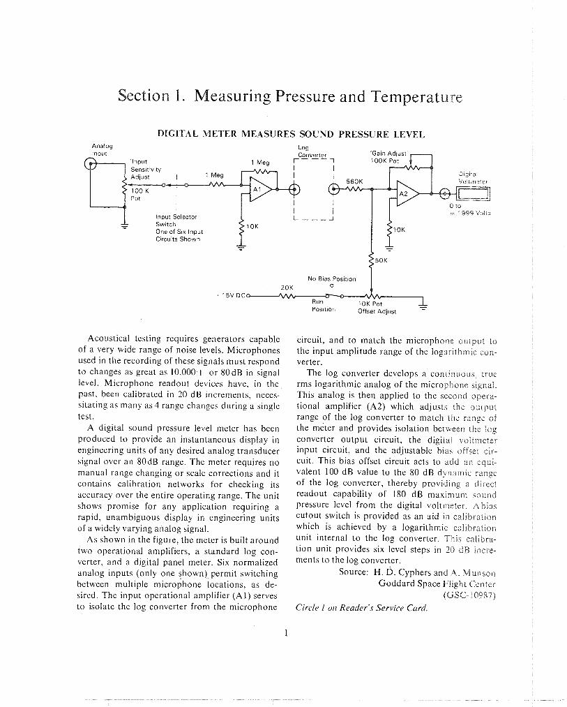
Acoustical testing requires generators capable of a very wide range of noise levels. Microphones used in the recording of these signals must respond to changes as great as 10,000.1 or 80dB in signal level. Microphone readout devices have, in the past, been calibrated i n 20 dB increments, neces- sitating as many as 4 range changes during a single test.
A digital sound pressure level meter has been produced to provide an instantaneous display in engineering units of any desired analog transducer signal over an 80dB range. The meter requires no manual range changing or scale corrections and it contains calibration networks for checking its accuracy over the entire operating range. The unit shows promise for any application requiring a rapid, unambiguous display i n engineer.ing units of a widely varying analog signal.
As shown in the figure, the meter is built around two operational amplifiers, a standard log con- verter, and a digital panel meter. Six normalized analog inputs (only one slhown) permit switching between multiple microphone locations, as de- sired. The input operational amplifier (Al) serves to isolate the log converter from the microphone
circuit, and to match the microphone output to the input amplitude range of the logarithmic con- verter.
The log converter develops a continuous, true rms logarithmic analog of the microphone signal. This analog is then applied to the seco~id opera- tional amplifier (A2) which adjusts the output range of the log converter to match the range of the meter and provides isolation between the log converter output circuit, the digital voitrneter input circuit, and the adjustable bias offset cir- cuit. This bias offset circuit acts to add an equi- valent 100 dB value to the 80 dB dynamic range of the log converter, thereby providing a direct readout capability of 180 dB maxiri-ium sound pressure level from the digital voltmeter. A bias curout switch is provided as an aid in calibration which is achieved by a logarithmic calibration unit internal to the log converter. This calibra- tion unit provides six level steps in 20 d B incre- ments to the log converter.
Source: H. D. Cyphers and A. Mulason Goddard Space Flight Celnter
(GSC- 10987)
Circle 1 0 1 1 Reader's Service Card.
2 M E A S U R t M E N T T E C H N O L O G Y
C O N C E P T F O R I M P R O V E D V A C U U M P R E S S U R E M E A S U R I N G DEVICE
This concept for measuring vacuum pressures in the range from 5 x 10" to 5 x torr should prove of interest to research and development manufacturers of vacuum tubes and related meas- uring devices. The basic element upon which the nleas~isirlg concept depends is a semiconductor resistor. composed of sintered zinc oxide. Through the effect of surface adsorbed gases on the resis - tance of semiconductor materials, very low pres- sures can be measured. N o existing techniques are capable of measuring low vacuum pressures below LO -!4 torr. Above this pressure range, the standard proccdiire has been to employ some form of elec- tron hornbardment-ionization svstem.
Vacuum System to be
/ /' Semiconductor Element
Ailandaid Light Source n Deveiopinent of sensing elements uniquely sen-
>nt:ve to ipecnf~c gas species has been an important con:ributlon to research in measuring very low pressure., The key element should have a large surfdce-to-volume ratio, and the carrier concentra- tion oi electrons in the bulk whtch dominates the sev\tanee characteristics of the specimen should
be highly sensitive to the surface adsorption of the species to be measured.
There are several methods which can be used to measure very low pressures. One approach is to monitor the resistance of the semiconductor ele- ment as a function of time under the vacuum conditions to be monitored before, during, and after illumination by visible light of moderate intensities. This light source can be inside or out- side of the vacuum system.
An alternate method is to substitute, for the standard light source inside the vacuum system, a simple filament placed in a pertinent geometrical relationship to the resistance element. This light source cleans the semiconductor surfaces by spe- cific mechanisms. The decay or increase in the resistance following the cleaning procedure is then monitored by the resistance bridge. By means of appropriate calibration, a direct reading of the vacuum conditions can be obtained.
Another procedure substitutes heat for photon light and cleans the resistance element with tem- peratures in the vicinity of 400°C. This can be achieved by a second filament placed near the original filament. A heat sink contact and standard flashing techniques can also be employed.
Source: D. M. Medved of Electro-Optical Systems, Inc.
under contract to Marshall Space Flight Center
(MFS-20172)
Circle 2 011 Reader's Service Card.
GALLIUM ARSENIDE T E M P E R A T U R E P R O B E H A S FAST R E S P O N S E
An mproved (faster response t ~ m e ) temperature p r o x ha., been developed for use in large tanks contannlng fluids at cryogenic temperatures. The pro 3e hcii the followtng character~stlcs tempera- ture range from -440" to +300°F; accuracy of LO OS'F, \ensit~vlty of 0 . l0F ; and stablllty of 10 001"$/6 months.
The probe has d tlme constant of 8 seconds o r ici i to temperature step change when brought Pror~ liqi:id hydrogen, nitrogen, o r oxygen to t h e ~ r reirirct ve \ t i l l gases above the l ~ q u ~ d W ~ t h o u t the
shield tube, time constant is about 0.2 sec. The probe is a rugged instrument, being able to with- stand 30 G's from 40 to 2000 cps and pressure to 3000 psi at cryogenic temperatures. The probe provides an output signal that can be transmitted by cable to an indicator as far as 2000 feet distant, and the signal is compatible with remote analog o r analog-to-digital systems.
The sensing element is a forward-biased p-n junction device made with gallium arsenide. The diode chip is housed in a small stainless steel tube
M E A S U R I N G P R E S S U R E A N D T E M P E R A T U R E
7 Teriniral Board 1
Sensor Assembly
/
welded shut at the sensing end and supported by Source: A. S. Benson of crosswires tied to a perforated shield tube. The Electro-Optical Systems, bnc. diode is mounted on a thin gold-plated alloy rib- under contract to bon (the cathode lead) with the anode connected by Marshall Space Flight Center a gold wire to the anode lead at an insulated ter- (MFS-12165) minal board. The small cross section of the sensor tube and its effective insulation from its support Circle 3 011 Reader's Service Card. structure result in its very rapid response to tem- perature changes.
CRITICAL TEMPERATURE INDICATOR: CONCEPT
Certain substances require close temperature that requires refrigeration from the time activators control between the time of preparation and the are added until usage. time of use. An example is a polymerizing adhesive A throw-away device has been coi~celved that
indicates if a packaged (canned) substance ha\ reached a temperature level that would adversely affect its quality. The principle of operation is the expansion of a colored jelly into a gigna'i chamber at the top of a sealed probe. The probe r y iri4ereed into an opening in the container lid at the trme of container filling and low temperature storage When the temperature of the adhesive reacbei the danger point, the colored jelly wlll expand into the capillary compartment of the probe and ctarn
Thermal Chamber the frosted glass in the probe head. Source. L Haifne~ of
North American Rockwell Corp under con1 ract to
Marshall Space Flight Center (MFS-9 1449)
Circle 4 011 Reader'& Service Card.
Section 2. Measuring Fluid Activities
DETECTING A N D MEASURING LEAKS IN THIN PLASTIC FILMS
Expulsion devices, such as bladders and dia- phragms, used to forcibly empty liquified gas con- iaineis, usually consist of several plies of plastic Ir l rn . each of which must be free of leaks. In con- venllondl leak testing, the expulsion device is piaced in a chamber and pressurized with helium gds. Gas accumulation in the chamber is then measured after a set passage of time (usually 24 hours). Th~s method affords an accurate measure- ment of leakage rate but does not locate the leak posltlon and 1s a time consuming operation.
Or~g ina l Probe \
O.Ring Effecttve \ Area ; 1.25 in2
hlslng an improved technique, individual plastic plies and the complete expulsion device can be checked for leaks by means of a helium leak detec- tor. Thc exp~~is ion device is pressurized with he-
lium to 0.5 psig and, after a 30-minute waiting period, its entire surface is scanned with a modi- fied helium mass spectrometer. Any standard mass spectrometer having a scale that registers 2 x 10⁻¹⁰ std cc/sec or less can be used. Modifica- tion to the probe, as shown in the figure, is in the form of a cup with a milled face that holds an O-ring in its end periphery which contacts the plastic film.
With one specific cup configuration, the mass spectrometer can measure helium leakage rates down to a level of 1.6 x 10-locc/sec/in~. The cup enables the operator to locate and to measure the relative- magnitude of a leak in a short time. The cross sectional area of the cup can be varied to meet different functional requirements. Source: R. E. Nelsen and E. H. Nicholson of
The Boeing Company under contract to
Lewis Research Center (LEW-10530)
Circle 5 on Reader's Service Card.
SPIRAL-FLOW APPARATUS FOR MEASURING PERMEATION O F SOLIDS BY GASES
An apparatus has been developed for measuring the rate of permeation of a solid by a gas.
The novel test assembly consists of two portions machined from metal, a shallow top and a deeper bottom with matching flanges; their inner diam- eter is ilominally 3.5 inches. In the inner face of the top,, a knife-edged spiral groove is machined from the periphery to the center. At each end of the groove a hole is drilled through the face, tapped, and fitted with a sleeve.
A cylindrical plug of the solid to be tested (such as a polymeric material), 3.5 inches in diameter and 718 inch thick, is pressed into the top until
the spiral knife edge engages its surface to a depth of 0.010 to 0.030 inch. The periphery of the plug is then sealed to the top with impermeable resin. The top and the bottom are then clamped to- gether over a gasket with a Marmon clamp.
Under pressure the test gas is admitted to the bottom. A carrier stream of gaseous helium is passed through the outer sleeve of the top, along the spiral groove, and out through the central sleeve to a gas chromatograph that detects the presence of the test gas. Thus, the rate of permea- tion can be determined. Its spiral passage ensures that all of the carrier gas traverses the entire sur-
MEASURING FLUID 'ACTIVITIES
face of the solid and that all is sampled. The mini- mum detectable rate of permeation is 2.5 x 10⁻⁵ cm3/sec (standard).
When tested for several days continuously, samples of a fire-retardent foam were impermea- ble by oxygen or nitrogen at 10 psig. When helium is the test gas, one of the sleeves in the top is sealed while the other leads to a helium mass spectrom- eter as a leak-detector. Samples of the same foam
showed permeabilities by helium of 6.2 and 7 9 \ 10-5 cmj/sec (standard). Source: S. M. Mitchell and B. B. '#illiai~~s of
North American Rockweil Corp. under contract to
Marshall Space Filghl Ccnter (MFS-16517)
Circle 6 oil Reader's Service Card
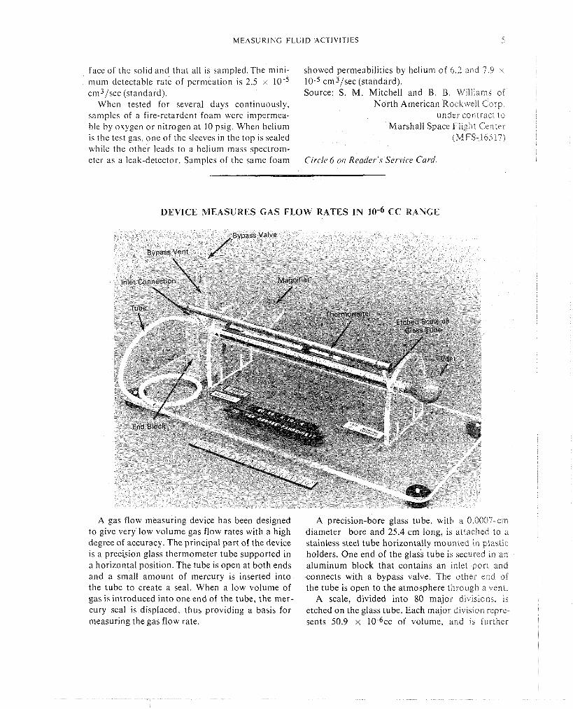
DEVICE MEASURES GAS FLOW RATES IN lom6 CC RAIVGE
A gas flow measuring device has been designed to give very low volume gas flow rates with a high degree of accuracy. The principal part of the device is a precbion glass thermometer tube supported in a horizontal position. The tube is open at both ends and a small amount of mercury is inserted into the tube to create a seal. When a low volume of gas is introduced into one end of the tube, the mer- cury seal is displaced, thus providing a basis for measuring the gas flow rate.
A precision-bore glass tube, with a 0.0007-cm diameter bore and 25.4 cm long, is attached to a stainless steel tube horizontally mounted in plastic holders. One end of the glass tube is secured in an aluminum block that contains an inlet port and connects with a bypass valve. The other end of the tube is open to the atmosphere through a vent.
A scale, divided into 80 major divisions, is etched on the glass tube. Each major divisron repre- sents 50.9 x 10⁻⁶cc of volume, and is further
6 M E A S U R E M E N T T E C H N O L O G Y
divided into five equal parts. An adjustable magni- iyrng glass 1s mounted above the tube for easy read- ~ n g of the scale The gas flow being measured is connected to the rnlet side of the glass tube with the bypass valve Left open until a stable flow is estab- Ilshed. The bypass valve is then closed, permitting the unknown gas volume to drive the mercury seal along the tube toward the vent. By timing the rate of travel oi the seal, low flow rates in the 10 -~cc
range can be determined. Any suitable timing device can be used to measure seal travel along the scale.
Source: T. J. B. Valdez of North American Rockwell Corp.
under contract to Manned Spacecraft Center
(MSC-11171)
No firrther documeiltation is available.
GAS LEAKAGE MEASURED I N REMOTE CHAMBER
A sysiern for collecting hydrogen gas leakage able chamber weighs 30 pounds and is equipped from a flange seal and piping it into a remote with a constant-volume accumulator which con- monitor chamber enables the pressure drop to be tains two thermocouples and a pressure transducer. measured In a safe environment. Previously, the Also in the chamber is a valve position and coil gas leakage was measured at the flange in a haz- current trace which indicates the position of a sole- ardous environment. noid-operated vent valve. This data is transmitted
Inlet (From Gas Collect~on
Constant Volume Accumula t~ t
Temperature Measurement
Pressure Measurement
Pressure Svvit I - - - .--I- I
Temperature Measurement
Valve Position 1 I
I I
Solenold 0p:rated Vent Monltor Chamber Vent Valve
The system includes a gas collection manifold which encloses the flange, so that leakage is piped into the remote monitor chamber. The port-
to a continuous strip chart recorder. The escaped gas which enters the accumulator is
monitored for temperature and pressure and these measurements also are transmitted to the recorder. The solenoid-operated vent valve, actuated by the pressure switch, prevents the accumulator pres- sure from exceeding a preset point. The valve auto- matically opens when the pressure exceeds the preset point and closes when the pressure drops to the reseat point. The data recorded are then used to calculate the rate of gas accumulation which corresponds to the gas Leakage rate.
This hydrogen gas system was designed to cycle between vent and reseat points of 28 and 26 psi, respectively. Tests indicated that the system was capable of measuring leakage rates to an accuracy of 1 5 % of full scale over a range of 250 to 2500 std cc/sec.
Source: S. K. Yoder of Aerojet General Corp.
under contract to Space Nuclear Propulsion Office
(NUC-90064) Circle 7 0 1 1 Reader's Service Card.
MEASURING FLUID ACTIVITIES 7
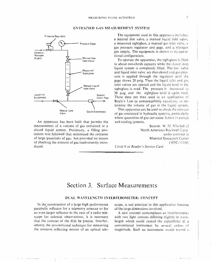
ENTRAINED GAS MEASUREMENT SYSTEM
Pressure Regulator The equipment used in this apparatus ~nciude\ a manual line valve, a manual liquid miet valve,
Pressure Gage a measured sightglass, a manual gas ~n le? valve, a gas pressure regulator and gage, and a nltrogcn -
Gaseous gas supply. The equipment is shown in rts opera- Nitrogen SUPP~V Manual Gas
Inlet Valve
Measured Sightglass
est
Manual Line Valve
Quick Disconnect
tional configuration. To operate the apparatus, the sightglass is filled
to about two-thirds capacity while the closed loop liquid system is completely filled. The line valve and liquid inlet valve are then closed and gas pres- sure is applied through the regulator until tile gage shows 20 psig. Then the liquid inlet and gas inlet valves are opened and the liquid level i n the sightglass is read. The pressure is increased to 30 psig and the sightglass level is agairi read. These data are then used in an application of Boyle's Law (a compressibility equation), eo de- termine the volume of gas in the liquid system.
This apparatus can be used to check the amount of gas entrained in hydraulic systems, particularly where quantities of gas can cause failure in pulnpc
An apparatus has been built that permits the and cooling systems. measurement of a volume of gas entrained in a Source: W. M. Mitchell of closed liquid system. Previously, a filling pro- North American Rockweil Corp. cedure was followed that minimized the entrance under contract to of large quantities of gas, but provided no means Manned Spacecraft Center of checking the amount of gas inadvertently intro- (MSC-i 1164) duced. Circle 8 o i l Reader's Service Card.
Section 3. Surface Measurements
DUAL WAVELENGTH INTERFEROMETER: CONCEPT
In the construction of a large high performance scope, is not practical in this application because parabolic reflector for a telemetry antenna or for of the large dimensions involved. an even larger reflector in the case of a radio tele- A new' concept contemplates an it~terferometer scope for celestial observations, it is necessary with two light sources differing slightly in wave- that the contour of the dish be precise. Interfer- length which could exceed the capabilities of a ometry, the conventional technique for measuring conventional instrument by several ordcrs of the concave reflecting mirror of an optical tele- magnitude. Such an instrument would record a
8 MEASUREMENT TECHNOLOGY
composlie fringe pattern representing a much greater meabiirement capacity than the pattern from a slngle light source. This concept would be applicable to any measurement to be made with an opticdi interferometer. However, the concept is most readily explained by using the example of ehe nieaaurement of a small angle between two reflecting surfaces. The angle can be calculated preciiely i f t he wavelengths of the light sources and the number of fringes displayed are known.
A limiting factor in the application of the instru- ment is the relatively short wavelength of visible light.
Source: R. E. Oliver of CaltechJJPL
under contract to NASA Pasadena Office
(NPO-11312)
Circle 9 oil Reaclrr'., Ser~Yce Can1
MOVABLE GAGE MEASURES BUTT WELD OFFSET
T o measure the offset between two butt-welded Vertlcal Adjustcng Bar and Clamp
panels, previous methods employed two gages
Horizontal Adjust~ng Bar set at an angle to each other. A new device has been fashioned that accomplishes a quick and direct measurement, on only one dial indicator, of any difference (offset) between the two butt- welded members' planes.
A long-stemmed dial indicator is operated by a surface contacting wheel and is mounted in a height adjusting clamp. This clamp attaches to a bracket and ball bushing arrangement that sup-
Weld Skate ports a large diameter (zero set) wheel that is held
Height Adlusting in intimate contact with one butt-welded member by imposition of a slight spring load. The vertical shaft and horizontal adjusting bracket are clamped as required for positioning in relation to an existing weld o r trim skate to follow the butt joint. As the spring holds the large (zero set) wheel in contact with one panel surface, the small wheel attached to the dial indicator follows the opposite side panel surface, thus furnishing a direct reading of any offset between the two panels.
Zero Set Wheel Source: D. R. Palmer of North American Rockwell Corp.
under contract to Marshall Space Flight Center
Welded Part Special lndtcator Wheel (M FS- 12688) and Bracket No f lrrther docurne~rtatiori is available.
S U R F A C E M E A S U R E M E N T S 9
FLATNESS GAGE MEASURES DIRECTLY
Flanges in high-pressure piping Systems must ~ ~ ~ h - ~ ~ e s s ~ r e D ~ a l lnd~cator
have mating surfaces with flatness that approaches that required in optical applications. The previous approach involved disassembly of leaky joint components and then making a flatness runout on a boring machine.
I n order to avoid the costly, time-consuming disassembly and checkout procedure, a tool has been designed that gives a flatness check of these flange faces in place with only disconnection in- volved. The tool consists of a plate that is flat within 0.0001 inch and that is bored through to accommodate a dial indicator so that the tip of its probe exten'ds a predetermined distance below the plate's flat surface. When the gage is moved over the surface of the flange face, an instant check of differences in flatness over the flange face is made by the dial indicator.
Source: A. Brooks of North American Rockwell Corp.
under contract to Marshall Space Flight Center
(M FS- 13975) No J~ l r ther doc~ir~~eirtatiorr ir available.
It is sometimes necessary to determine the di- mensions of organic components within metallic housings and neutron radiography is useful for this purpose but is not generally available. By surrounding such organic components in a radio- graphically dense liquid, it is possible to radio- graph them by ordinary X-ray techniques. I f all cavities within the housing are filled with the dense liquid, a complete volumetric outline of'the organic components can be obtained. Such an outline is in the form of a "negative" (dark) image in contrast to conventional radiography.
High-density fluids may be made by d i s so l j i i~~ heavy metal salts in a carrier fluid, or by suspend- ing finely-powdered materials in gels or emul- sions. Such a dense compound as freon 114-B2 may be used, but its reaction to the organic com- ponents must be tested. This noncorrosive freon is a cleansing agent, and is thus preferred where proven inert toward the organics preseni.
Source: R. &. BI-OMIEI, Sr. Marshall Space Flight Center
i M FS-20528) No f irrther docllr)~eiltatiotl is available
10 M E A S U R E M E N T T E C H N O L O G Y
1NSTRUMENT ACCURATELY MEASURES CONCENTRICITY
AIP instrument has been developed to measure multiple concentric surfaces on any round base the concentricity of flared tubing ends. The in- diameter. The tool-making industry and any in- sirurrient should find application in many indus- dustries involved with high pressure fluid transfer tries as a rapid and accurate method to measure could benefit from the use of this instrument.
The instrument consists of three high precision ball bearings arranged in a vee that can be ad- justed in size by raising o r lowering a movable upper portion of the device. A dial indicator rides on the upper portion with its probe located above and outboard of the opening between the bearings. The item under test for concentricity measurement is placed above the two lower bear- ings and the upper portion is lowered until its bearing contacts the item. The wing nuts are tightened until firm contact is obtained between the item and the three bearings. The dial indicator probe is adjusted to contact the surface to be measured and the item is slowly rotated. Any movement of the indicator pointer shows a non- concentric area.
Source: C. A. Goodwin of The Boeing Company
under contract to Kennedy Space Center
(KSC- 10290) Ci rc le 10 oir Reader' \ Service Car(/ .
Section 4. Linear and Angular Measurements
MODIFIED SINE BAR DEVICE MEASURES SMALL ANGLES WITH HIGH ACCURACY
The principle of the sine bar has been adapted to the calibration of precision optical autocolli- mators. I n this application, it was required to measure angles over a range of 1.00 arc-second in incren~ents of 0.05 arc-second, with a maximum error of 20.01 arc-second in any given increment.
The required measurement accuracy over this extremely small angular range was achieved with the sine bar device shown in the drawing. In this
design, the sine bar is a massive bar of steel sup- ported on a fixture by two cylindrical rods near the left end and by dne cylindrical rod in a V-groove near the right end. By placing precision gage blocks between the rods on the left end, the sine bar may be made to rotate about the cylindrical rod on the right end. The effective length of the sine bar as measured by the distance between the axes of the cylindrical rods at either end is
LINEAR A N D A N G U L A R M E A S U R E M E N T S 1 6
20.025 inches. A mirror is rigidly fastened to the right end of the sine bar to deflect a beam of light through an angle twice that of the sine bar rota- tion. Thc autocollimator to be calibrated is placed in front of the mirror. Angles of the required mag- nitude and accuracy can be generated by a set of 20 commercially available gage blocks which are calibrated in increments of 5 x loT6 inch, and are guaranteed in flatness and thickness to
inch. By replacing a gage block with another in the series, the normal to the mirror rotates in increments of very nearly 0.051t0.01 arc-second.
S ~ n e Bar Mirror
I Rods Gage\Block \
\ Support F~xture Rod
Use of the two cylindrical rods on the left of ehz sine bar eliminates one major source of cri-or d ~ l i : to the variable air films between a gage block in contact with plane metal sul-faces abovc and below it. Such an air film might well be of the order of magnitude of the incremel-its in the gage blocks. When a gage block is in position between the cylindrical rods a s shown, there are only liiie contacts with the rods so that the air films are effectively eliminated. The V-groove surface is provided to minimize backward or forward dis- placement of the sine bar. This groove is lapped to the rod, so that the two surfaces make an 80 percent line contact through a miriirnum of 3 de- grees of rotation. A thumbscrew inay be provided on the support fixture close to the left end of the device, to permit the sine bar to be raised OT
lowered without lateral displacement. Source: M. Thekaekora
Goddard Space Fligill Center (6 SC- 10438)
Circle 11 o i l Reader's Service Card.
PHOTOMICROMETROLOGY
It is necessary to determine accurately, the physical dimensions (angles, contours, etc.) of the microscopic details of very small components when they must meet exceedingly fine tolerances.
A method known as photomicrometrology that combines microphotography with standard meas- uring techniques makes this possible. Where a microphotograph cannot be directly applied due to the inaccessibility of the part involved, a mold can be used to determine the angle o r contour of interest.
A photograph is taken through a microscope, set at a predetermined level of magnification, and the resultant negative is overlaid on an optical scale of the same magnification, as shown in the sketch. In those cases where the location of in- terest does not permit direct microphotography, a standard commercially available molding plastic substance is used to make a reverse contour which can be removed and photographed through the microscope. This microphotograph is then meas- ured in the same way to give the desired results.
Part Photograph
This technique has been succec~\ful!y u i ~ d to achieve proven measurements to 25 mlcroii~che,
Source: F. L. Young of North American Rockwe!' Corp
under contract to Marshall Space Flrght Center
(MFS- 14556) Circlc 12 on R~>ader's Service Card
12 MEASUREMENT TECHNOLOGY
LIIAMETRAL THERMAL EXPANSION MEASUREMENT O F TUBING
In order to measure the diametral thermal ex- pansion of Ta/316 bimetallic tubing, a modified form oi' the standard quartz pushrod technique has been s~iccessfully used. In this application, one end of a quartz push'rod is attached to a ring that surrounds and contacts the tubular specimer~ at a point opposite a pedestal.
A vertical quartz tube having a flat, polished end serves as the pedestal within which the push- rod i s mounted and upon which the specimen rests. The lower end of the pushrod is attached to ihe core of an electromechanical transducer. The coil of rhe transducer is mounted in the lower end of the pedestal. The pushrod is not subject to slid- ing friction since it hangs on the specimen and-is capable of following very small dimensional changes in the specimen. Movement of the push- rod and transducer core causes a change in the coil output and this change is fed to a direct read- out device.
Quartz Pushrod Source: P. S. Gaal of
Westinghouse Astronuclear Lab. under contract to
Lewis Research Center (LEW- 1085 1) Transducer Core
Circle i3 t i i t Rrac/er'.s Service Carci.
INSTRUMENT ACCURATELY MEASURES HOLE CENTERLINES
Section A-A I
Figure 1 Figure 2
Detesminaling hole centerline distances previ- sources and required considerable time to ac- ously iavoived three separate measurements and complish. An instrument has been designed that calculation\. This introduced three potential error permits hole centerline distance determinations
L I N E A R A N D A N G U L A R M E A S U R E M E N T S 13
to be made directly, requiring no additional measurement o r calculation.
The hole centerline measurement instrument shown in Figure 1 uses cones to locate the center- lines of holes, and translates these locations to a scale. Cones are used because they will always seek hole centers throughout a wide range of di- ameters. One cone is attached to the zero end of the scale and the other is attached to a moveable slide in a channel. A pointer translates the center of the moveable cone, which is in the centerline
of the hole ~t rests in, to the scale S ~ C L I O I ' E ~ I view\
A-A and B-B of Flgure 2 further riiu\tr,ire liie construction of the hole centerl~ne rneic:irlng instrument.
Source R W Leinke of The Boeli~g C O I F ~ ~ ~ E I ~
under corIirJc\ to Kennedy Space Center
(KSC- 10226)
No Jtrrther doczli?zerltatiorl is available.
INSTRIJNIENT ACCURATELY MEASURES DISTANCES FROM EDGES OR HOLES
An instrument has been designed to make ac- curate measurements from edges or holes without the necessity of extensive layout. When herrnaph- rodite calipers are used to make measurements from holes o r edges, the inside o r bowed leg is free to travel up or down the vertical surface. Such movement can result in inaccurate measure- ments o r markings.
To eliminate this vertical movement o f the bowed leg, the instrument shown in the figure substitutes a flange on a cylindrical pivoting end of one member in place of the bowed leg of the hermaphrodite caliper. This flange stops the instrument at the horizontal surface and permits the preset distance to the marking leg (pointer) to be maintained. I n use, the modified caliper is set to the indicated distance by measuring from the inside of the flanged pivoting member to the tip of the pointed member. The measurement figure has one half the hole diameter added for a centerline measurement.
Source: R. W. Lemke of The Boeing Company
under contract to Kennedy Space Center
(KSC- 10225) No further d o n ~ ~ ~ ~ e ) r f a t i o r l i r available.
\\\ Pointed Member
1 4 M E A S U R E M E N T TECHNOLOGY
DIFFERENTIAL TRANSFORMER IVlEASURES AXIAL SHAFT LOAD OR DEFLECTION
Ail aiinular differential transformer has been designed to measure axial shaft load and deflec- tion for rotating equipment. The transformer with a pvlytetrafluoroethylene nosepiece is at- tached to an axially movable core and mounted 011 the shaft. Direct measurements of axial move- ilieilt of the shaft are provided.
P l a s t ~ c Nosepiece
Secondary Coils
In operation, a highly polished mating ring (similar to a carbon nose bellows seal) is attached to the shaft. The differential transformer nose- piece is held in intimate contact with the mating ring by a number of light springs bearing against the body of the transformer. Axial movement of the shaft produces a n equal movement of the nose and core, changing the magnetic flux estab- lished by the primary core which is stationary in the transformer housing. The voltage induced in the secondary coils by the core is measured as a delta voltage proportional to the core move- ment.
Source: C. A. Johnson of North American Rockwell Corp.
under contract to Marshall Space Flight Center
(M FS- 13302) No further doclr~nei~tat io~~ is available.
L I N E A R A N D A N G U L A R M E A S U R E M E N T S 15
uses rocker assemblies and check links for truck and railroad scales, but investigation has shown that this installation allows the load cells to tilt with no means of determining the degree of tilt.
The sketch shows an improved weight stand that assures true axial loading determination. Three o r more such stands are required to form a complete weighing system for large, heavy ob- jects. Weight of the object resting on the stage fitting is brought to bear on the adapter fitting, and deflection in the object tends to impose hori- zontal loads on the installation. Horizontal move- ment check assemblies transmit these loads into the stand rather than to the load cell. I f horizontal forces are sufficient to deflect the stand, o r if there is play in the check assembly, the horizontal force applied to the load cell will cause the cell to tilt. When this occurs, the degree of tilt can be determined by the precision spirit levels. An an- gular tolerance can be established in calibrating
the system since it has been found that miiior deviations (less than 1.0") have little effect on either accuracy or repeatability. This i s also borne out in theory, since the loads sensed by the load cell are cosine functions of the angle between the load cell column and the vertical, as referenced to gravity.
The cardboard disk has improved repeatability from approximately 10.05 percent to approxi- mately *0.025 percent by providing heaer load distribution into the bottom of the load cell. 'The rocker mounting studs and springs are used to adjust the cell mounting plate level under iio- load conditions.
Source: L. 6. Smart of The Boeir-ig Cornpai~y
under cor~iract to Marshall Space Fliglit Center
(M f5-9 i 429) Circle 14 or^ Reader's Service Card.
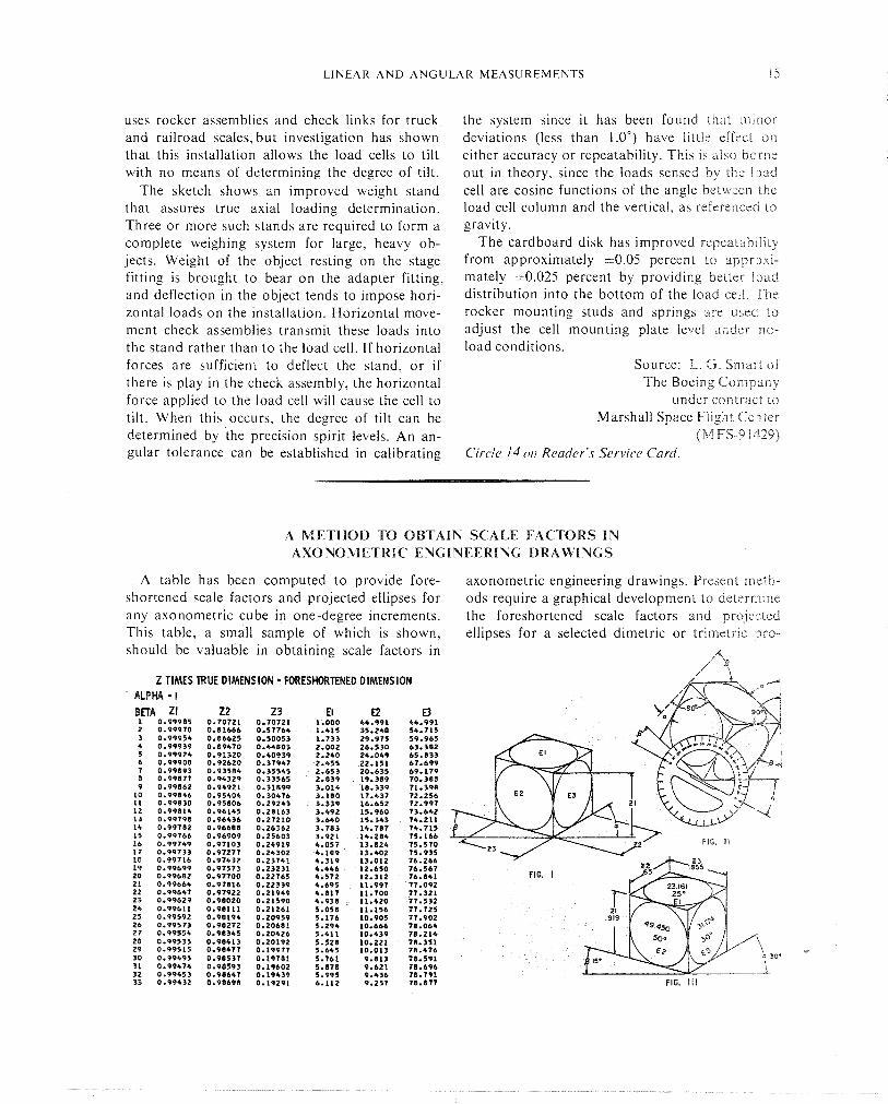
A METHOD TO OBTAIN SCALE FACTORS I N AXONOMETRIC ENGINEERING DRAWINGS
A table has been computed to provide fore- shortened scale factors and projected ellipses for any axonometric cube in one-degree increments. This table, a small sample of which is shown, should be valuable in obtaining scale factors in
Z TIMES TRUE DIMENSION - FORESHORTENED DIMENSION ' ALPHA - I
axonometric engineering drawings. Present meih- ods require a graphical development to determine the foreshortened scale factors and projected ellipses for a selected dimetric or trirnetric pi-o-
A ' 4
FIG. ill
16 M E A S U R E M E N T T E C H N O L O G Y
jcctloxl ilr'iw~tig. T h ~ s innovation ellminates the gruphrc,~! dcvelopment requirement and offers rxirlzdl'ite lookup of the scale factors and pro-
J e ~ ~ e d eilipici for a selected axonometric projzc- Inon
C,>rnp~"eb for every alpha degree are all the beta dcerees 'lrid \ix columns of numbers. Under 'he l i r \ i three columns (Zl , 22 , Z3), are listed he fc.rt.shor~cn~ng factor\ for the three axe\ of a i ubc , ,ii?d tile other three co lun~ns ( E l , E2, E3)
list the degree of the ellipses for the corresponding planes. This system provides every possible meas- urement factor and ellipse in one degree incre- ments from zero to 90".
Source: R. Chu of North American Rockwell Corp.
under contract to Manned Space Flight Center
(MSC- 15829) C'ircl~~ 1s o i l Rrar/er'.c Service Card.
MODIFIED MICROSCOPE PROVIDES DEPTH MEASUREMENT
T!IC depth of voids, pits, o r depressions in ma- terial t e s ~ specimens can be measured nonde- st.ruciivciy by a dial indicator and a wide-lens inicroscope. Prior methods involved destrirctive cross sectionir~g of the part or the use of a measur- ing iilstrui'i~eii: in conjunction with, but not at- laelled :o, tile microscope. The modified micro- scojie provides more accurate measurement, is easier. to calibrate, and requires less handling of speciAnelis by the operator than previous methods.
The adaptation equipment includes: a wide-field stereoscopic microscope, a calibrated rnicronieter dial indicator, and a dial indicator guide and adjustment bar. The rack and pinion head adjust- ment of the microscope is modified to allow instal- lation of the dial indicator.
Depth measurements are carried out by the following procedure: The test specimen is secured under the microscope, and the lens system is ad- justed until the surface of the specimen is in focus.
L I N E A R A h D A N G U L A R M E A S U R E M E N T S 17
The dial indicator is lowered on the guide and adjustment bar until the indicator probe is in con- tact with the microscope lens system housing. The indicator dial is then adjusted to zero. When the lens system is lowered to focus on the bottom of the depression, pit, or void on the specimen, the adjustment for focus indicates the depth of the depression, which can be read directly from the micrometer dial indicator.
The modified microscope is accuraie to O . 0 O O i inch.
Source: L. W. Jackson of North American RockweiE Corp.
under contract to Manned Spacecraft Celircr
(MSC-3 1223)
S Y S T E M M E A S U R E S L I N E A R A N D A N G U L A R DIMENSIONS OF V E R Y L A R G E S T R U C T U R E S
A system has been developed that will enable accurate and rapid measurement o f linear and angular dimensions of very large structures of any configuration.
A precision rotary table has been combined with an integrated optical tooling bar system that can be used for measurement of structures with horizontal dimensions of up to 45 feet and a maxi- mum height of 30 feet. Linear dimensions can be rapidly measured to an accuracy of 0.005 inch, and angular dimensions can be measured to within 2 seconds of arc.
The structure to be measured is mounted on the turntable which can be rotated 360" to expose any desired surface to sighting by the optical tool- ing bars. The table turns on a bearing which is fully compensated by pressurized fluid in both the radial and thrust planes. The bearing provides a precise, stable, essentially frictionless axis of rotation and will support a weight of up to 40 tons.
There are three tooling bars, two horizontal and one vertical, which are located around the periph- eryof the turntable. The horizontal tooling bars are stationary and situated 90 degrees to each other
along two sides of the turntable. The vcrticai 1001-
ing bar is mobile and located at the outer end of one of the horizontal tooling bars. LJsii~g lateral adjusters mounted on the table, the structure to be measured is centered to within 0.005 inch (total indicated reading). The structure can il-ren be rotated while maintaining a parallel relatison- ship to the horizontal tooling bars and a perpendic- ular relationship to the vertical tooling bas. Lineal- measurements are made through the use of rnaslcr indexing bars on each of the tooling bars, with the table in a stationary position. Angular measure- ments are made by rotating the table with respect to a stationary point on one of the tooling bars.
The equipment includes readout sysien~s thai provide direct linear and angular indications. The linear readout is in inches, and the angular readout is in degrees, minutes, and seconds.
Source: R. R. Simpson of The Boeing Company
under contract to Marshall Space Flight Ceilter
(MFS- 92477) Circle. 16 oir Reader's Service Card.
A D J U S T A B L E D I A L S C A L E
An elastic scale permits readout dials to be The components of the adjustable dcal scale are easily adjusted so that they indicate true calibrated shown in the illustration. T o construct the devize. values. Previously, readout dials were calibrated strips of bonded elastic material which cont,iin by means of charts or curves; instrument values both locating and stiffening pins, are prepared were taken and true values determined secondarily according to the required dimensions of the icstru- f rom the gathered data. ment in use. A number or letter scale w1t1-i he
18 M E A S U R E M E N T T E C H N O L O G Y
Section A-A
Sponge Rubber
The holder device for the elastic scale may be incorporated either as a part of the instrument face or as a separate item attached to the instru-
a p p r ~ p r i a t e range is marked on one side of the ment. The stiffening pins and bonded configura- eiasiii: material. The scale is then secured on the tion of the elastic scale cause it to stay in the de- readout dial by a front plate, back plate, and re- sired position and maintain uniformity in the dial L L L I I I ~ ~ . value increments, after the adjustment.
The instrument is calibrated and the dial scale Source: C. A. Minton and E. D. Wallace adjus~ed by moving the locating pins around a Kennedy Space Center .ierraied lip on the front plate of the dial face until (KSC-66-5) iihe pointer r e a d s the true values. No firrther c i c ru~ze~ l ta t io~~ is available.
S Y S T E M F O R M E A S U R I N G R O U N D N E S S A N D C O N C E N T R I C I T Y O F L A R G E T A N K S
Lq":rmcnt has been under development for ne'ii~iring the roundness and concentrlclty of argc, ni,i\ilvz tanka. The equipment includes a
34-.loot i o t ~ i r y table, a varlable reluctance d ~ s - placcincci tr,ln\ducer, an electronics console, a digltdi ~ornpu te r , and a %foot plotter used for rind; iJat,l d ~ \ p l a y Operation of the system IS rela- 1:ve;y >rmple ,~nd straightforward. Test results In- dl~clte that measurement accuracy of 0.003 Inch i\ r c a d ~ l y a~ t~ i inab le on a 34-foot dlameter (7 36 x
per ~ e n t ,tccuracy)
In making measurements on a large tank posi- tioned on the rotary table, the variable reluctance transducer is positioned against the tank t h r o ~ ~ g h a precisely ground cam. As the rotary table moves the tank past the cam, any deviation from a preset zero reference point correspondingly changes the reluctance of the transducer. The resultant output voltage, corresponding to the deviation, is fed through a signal conditioning amplifier to a calibra- tion panel. The output from the calibration panel is a direct analog in millivolts per inch of deviation.
This analog voltage is passed to a digital voltmeter where the signal is displayed as inches of deviation and processed illto a binary coded decimal format. While these measurements are being made, an angular readout unit displays 0.1-degree incre- ments of rotation of the rotary table. Data from the readout unit are fed to a logic panel and to a preprogra~iiniable counter. The counter may be programmed to allow readings at any multiple of degrees o r tenths of degrees, enabling the inspec- tor to make from 1 to 36,000 measurements per rotation of the table. The counter also supplies speed information to the central logic system.
The measurement data are coded on tape, giving the deviation of any specific point and the rota- tional speed of the table at the time the reading
was taken. The taped data are c o r ~ ~ c r l e d i i ~ i o ail acceptable form for the large plotter A p<litern of the tank 1s then plotted shaming ,ill dtvl,itior~\ from the reference polnt.
T o measure the vertical conceiitricltj o i lilt
tank, it is only necessary to take a \z t ot i c ,~ding\ at two or more axially perpendicui'ls p i L ~ n c ~ through the tank and plot the resultant circ c \ oi- the large plotter.
Source. R E Mc1,oi-i ol SPACO. Inc
undcr co,itr,ict to Marjhall Spacc Fllphi Center
(M FS- 13362 i
ALdJClST,\BLE SCALE: POSITIONER HOLDS TRUE VERTICAL POSITION
A leveling bracket has been developed for positioning a steel scale in a true vertical position. The device consists of a caster-mounted tripod base and an adjustable ball and socket mount which permits a d j ~ ~ s t m e n t of the scale vertical attitude by means of two turnbuckles mounted at right angles to the scale.
The scale is located and clamped in the slotted area of the positioner with the bottom of the scale resting on the surface where flatness is to be de- termined. A leveling bubble is located in the upper portion of the scale. The turnbuckles are adjusted and the leveling bubble is used to locate the scale in a true vertical position. Optical readin,. 0 s can then be taken t h r o ~ ~ g h a sight level to the scale with the scale maintained in a rigid position, thus eliminating the movement that. occurs when the scale is hand-held. Once the scale has been set, readings desired in othcr locations can be taken by rolling the positioner from place to place.
Source: Ronald J. Mohr of North American Rockwell Corp.
under contract to Manned Spacecraft Center
(MSC-15623) hro.firrther dociin~r~rtatioi~ is availcrble.
POSTAGE AND FEES PAID NATIONAL AERONAUTICS AND
SPACE ADMINISTRATION
NATIONAL A E ~ I A U T ~ m m LACE ADLCINIS~WION W A S B ~ ~ M , D. c. lor46
OliprgU BwmESS W M A U ' f R7R WVlrCITE UM (3U
msTMASTER: If Undeliverable (Section 158 Postal Manual) Do Not Return
7--
"The neronazttical mtd space activities of the U~zited States shall be cond~fcted so as to cofttribl~k . . . to the expunsion of hr/~lzan knozul-
xvcS,
edge of pheno?llenn in the at~izosphere ngzd Jpace. The Adnzinistmtion shall provide for the widest practicable and nppropriate dissenzination of informmion concerfzing its activities m d the resz//ts thereof?
--NATIONAL AERONAUTICS AND SPACE ACT OF 1958
NASA TECHNOLOGY UTILIZATION PUBLICATIONS
These describe science or technology derived from NASA's activities that may be of particular interest in commercial -and other non-aerospace applications. Publications include:
TECH BRIEFS: Single-page descriptions of individual innovation;, deviies, iethods, or concepts.
TECHNOLOGY SURVEYS: Selected surveys of NASA contributions to entire areas of technology.
I.
OTHER TU PUBLICAYIONS: These include handbooks, reports, conference proceedings, special studies, and selected bibliographies.
Details on the availability of these publications may be obtained from:
National Aeronautics and
Space Administration
Code KT
Washington, D.C. 20546
Technology Utilization publications are part
of NASA's formal series of scientific and
technical publications. Others include Tech-
nical Reports, Technical Notes, Technical
Memorandums, Contractor Reports, Technical
Translations, and Special Publications.
Details on their availability may be obtained from:
National Aeronautics and . Space Administration
Code KS
Washington, D.C. 20546
NATIONAL AERONAUTICS AND SPACE ADMINISTRATION Washington, D.C. 20546


![Centers for Turning and Grinding - Powerhold, Incpowerholdinc.com/uploads/products/21_CarbideDeadCenters[1].pdf · Carbide dead centres Roundness achieves roundness When grinding,](https://static.documents.pub/doc/80x56/5a7e878f7f8b9a66798e90ae/centers-for-turning-and-grinding-powerhold-1pdfcarbide-dead-centres-roundness.jpg)


