Designed for accuracy and ease of use, the Factair F3000 Safe-Air Tester is the fourth generation of this market-leading instrument. Using the unit to conduct monthly checks of the flow and purity of compressed-air breathing systems will ensure compliance to the relevant requirements of COSHH L5.
With speed and repeatability as prime objectives, the need for manual adjustment of flow and timing has been removed. Once the equipment has been set up on site, tests are carried out automatically and the detection parameters of EN12021:1998 met or exceeded.
Simple precautions and attention to the operating instructions will ensure that the F3000 provides many years trouble-free operation. Please read this manual fully before operating the unit.
Calibration and Warranty
Safe-Air Testers leave our factory with a 12-month warranty and calibration certificate. Our standard turnaround on annual calibration is 10 working days providing there is no major damage that requires extensive rebuild. Inside the carry case there is a laminated sheet listing the detector tubes that your Safe-Air Tester is calibrated for and information on how to read them. Alternative types of tubes may not be used without recalibration of the instrument by Factair.
The date your tester was last calibrated is shown on the digital display.
Note: It is recommended that your F3000 be calibrated within a 12-month period.
It is the responsibility of the user of this equipment to ensure that it is operated and maintained in strict accordance with these instructions. The Manufacturer and Distributor shall not be liable for any incorrect measurement or any damages, resulting from negligence or incorrect use.
- 1 -
2 BATTERY AND POWER SUPPLY
The unit operates from 6 off type AA batteries. (Long life Alkaline-type preferred.) Note: Do not use rechargeable batteries. The battery condition is indicated on the digital display either OK or LO. If the battery indication momentarily indicates LO then the batteries will need to be replaced as soon as practicable. Note: The tester will not permit operation with battery LO permanently indicated, however, if the LO sign is indicated during the test then the test will complete its cycle but no repeat tests will be permitted. The screen will display~ “Battery low Replace batteries” To replace the batteries: (i) switch off the tester (ii) turn the unit onto its back (iii) release the battery tray lid situated in the base of the tester (iv) remove old batteries and refit new batteries ensuring that polarity is
correct, (ie + to + and - to -) (v) dispose of used batteries in a responsible manner. Note: The unit will automatically switch on when new batteries are fitted. The F3000 can also be operated from the supplied mains adaptor irrespective of the battery condition. The power input socket is situated at the rear of the tester’s base. Note: Ensure the unit is switched off prior to connecting and disconnecting the mains power supply.
- 2 -
3 OPERATION 3.1 Testing of low-pressure breathing airlines and mobiles
(i) Turn on power by pressing and holding the ON/OFF button on the
keypad for approximately 2.5 seconds. The unit will display the model and serial number.
Press enter to confirm the date of the last calibration and the battery condition.
Note: It is recommended that your F3000 is calibrated within a 12-
month period.
(ii) If the battery condition is OK
Press enter (iii) Ensure the system flow control valve is closed then connect the air
supply from the breathing-air system to the tester via a suitable hose
Note: Minimum inlet pressure 1.5 bar
Maximum inlet pressure 10 bar. Press enter IMPORTANT: If the unit is overpressurised it will automatically shut down and display an overpressure warning; it will then need to be returned to the manufacturer for inspection and resetting. Note: The above service is chargeable.
(iv) Adjust the system flow control valve so the normal flow required for
the face-piece shows on the flowmeter, best achieved by raising beyond the set point and lowering the flow so the flowmeter reads the required value. (120 litres for half and full masks, often more for air-fed visors, hoods and suits; check flow requirements with the appropriate RPE data sheet.) It is recommended that this flow is left running for the duration of the test to simulate the conditions of use. Carry out the odour test by smelling the air exhausted from the sintered outlet above the flowmeter.
- 3 -
Note: If there is a serious odour problem, fail the sample at this point of the test. Running the tester with seriously contaminated air can damage the unit.
Press enter
Detector Tube Set-up Note: CO and CO2 are set. Water and oil channels are variable and
must be set as below:-
(v) Select water range by means of the up/down scroll buttons
HI 50 – 2000 mg/m³ for standard airline use LO 5 – 200 mg/m³ for airlines incorporating a desiccant dryer. Press enter
(vi) Select oil time
Screen will display: Preset times Add custom time These are selectable by using the up/down scroll buttons Press enter Select according to the following requirements|:-
(vii) Preset times
The following common times are available within the preset times menu and are selectable using the up/down scroll buttons Press enter
- 4 -
Previously programmed custom time* -- 15 mins (default)
7 mins 30 secs 3 mins 45 secs 2 mins 15 secs
* (will display 00 mins 00 secs if not set.) The system automatically defaults to “15 mins”; if you have no knowledge of the type of compressor lubricant being used in the breathing-air system then accept the default time of 15 minutes by pressing enter If you can determine with a high degree of certainty the specific compressor lubricant being used, then refer to the “test times” chart provided using the column marked for the F3000. If the required test time is one of the quoted preset times then select using the up/down scroll buttons Press enter
Note: for a test time not listed in the preset menu select “Add
custom time” at (vi) Press enter
(viii) Add custom time
Using left/right scroll buttons move the cursor over the time to be altered and set the appropriate time using the up/down scroll buttons . When the correct time is set Press enter
Note: The previously set custom time is made available in the
preset times menu for ease of use with repeat tests.
(ix) Confirm all settings are correct, select ‘Y’
Press enter
OR
- 5 -
If you wish to amend a setting use the left/right scroll buttons to select ‘N’
Press enter Then repeat procedures from (v).
(x) The unit will commence a 5-minute purge. When complete the display will indicate:-
Purging complete Insert tubes Start test
(xi) Cut both ends of the detector tubes with the special cutter provided
and ensuring that no glass shards are present in the glands, insert the tubes into the relevant ports and tighten the gland covers. Always check to ensure tubes are inserted correctly with the arrows pointing outwards.
Press enter
(xii) Testing time will be displayed as a countdown, together with airline
temperature, ambient temperature, oxygen content and airline pressure. The status of the individual tests is indicated on the left-hand side of the display. Black: test active, clear: test completed. The unit can be left until testing time has elapsed.
(xiii) Display will read:-
Testing complete Take readings Restart or turn off Close the system flow control valve. The digital readings for airline and ambient temperatures, oxygen content and airline pressure are now locked and these results should be recorded. Remove all the tubes and record results on the Factair result pad.
- 6 -
Note: For instructions on reading detector tubes and their safe disposal, refer to the laminated sheet stored within the tester’s carry case (also added as an appendix within this manual).
Refer to Appendix 4 within this manual for information converting detector tube readings to a dewpoint.
(xiv) To restart the tester for a subsequent test, momentarily depress the ON/OFF button. To switch off the tester, depress and hold the ON/OFF button for approximately 2.5 seconds.
Note: The tester will automatically switch off, if not used, after a period of 1 hour.
3.2 Testing high-pressure cylinders (i) Turn on power by pressing and holding the ON/OFF button on the
keypad for approximately 2.5 seconds. The unit will display the model and serial number.
Press enter
to confirm the date of the last calibration and the battery condition.
Note: It is recommended that your F3000 is calibrated within a 12-
month period.
(ii) If the battery condition is OK
Press enter (iii) Ensure the system flow control valve is closed then connect a hose
from a regulated high-pressure supply to the air inlet on the tester. A high-pressure regulator and hose assembly, reference F3002, is available for this purpose. Ensure the cylinder is fully charged by reading the content gauge. (A partly discharged cylinder can give an incorrect water test result.)
Note: Maximum inlet pressure at the tester is 10 bar.
- 7 -
Press enter IMPORTANT: If the unit is overpressurised it will automatically shut down and display an overpressure warning; it will then need to be returned to Factair for checking and resetting.
Note: The pressure displayed will be that of the regulated supply from the cylinder, this must not exceed 10 bar.
(iv) Gently open system flow control valve until a minimal flow is passing. Immediately carry out an odour test by smelling the air exhausted from the sintered outlet above the flowmeter, then close the system flow control valve. Use the minimum amount of air to preserve cylinder capacity. Note: If there is a serious odour problem, fail the sample at this point of the test. Running the tester with seriously contaminated air can damage the unit. Press enter
Detector Tube Set-up Note: CO and CO2 are set. Water and oil channels are variable and
must be set as below:-
(v) Select ‘LO’ 5 – 200 mg/m³ water range by means of the up/down scroll buttons Press enter
(vi) Select oil time
Screen will display: Preset times Add custom time These are selectable by using the up/down scroll buttons Press enter Select according to the following requirements:-
- 8 -
(vii) Preset times
The following common times are available within the preset times menu and are selectable using the up/down scroll buttons Press enter
Previously programmed custom time* -- 15 mins (default)
7 mins 30 secs 3 mins 45 secs 2 mins 15 secs
*(will display 00 mins 00 secs if not set.) The system automatically defaults to “15 mins”; if you have no knowledge of the type of compressor lubricant being used in the breathing-air system then accept the default time of 15 minutes by pressing enter If you can determine with a high degree of certainty the specific compressor lubricant being used, then refer to the “test times” chart provided using the column marked for the F3000. If the required test time is one of the quoted preset times then select using the up/down scroll buttons Press enter
Note: for a test time not listed in the preset menu select “Add
custom time” at (vi) Press enter
(viii) Add custom time
Using left/right scroll buttons move the cursor over the time to be altered and set the appropriate time using the up/down scroll buttons . When the correct time is set
- 9 -
Press enter
Note: The previously set custom time is made available in the preset times menu for ease of use with repeat tests.
(ix) Confirm all settings are correct, select ‘Y’
Press enter
OR If you wish to amend a setting use the left/right scroll buttons to select ‘N’
Press enter Then repeat procedures from (v).
(x) The unit will commence a 5-minute purge. When complete the display will indicate:-
Purging complete Insert tubes Start test
(xi) Cut both ends of the detector tubes with the special cutter provided
and ensuring that no glass shards are present in the glands, insert the tubes into the relevant ports and tighten the gland covers. Always check to ensure tubes are inserted correctly with the arrows pointing outwards.
Press enter
(xii) Testing time will be displayed as a countdown, together with airline
temperature, ambient temperature, oxygen content and airline pressure. The status of the individual tests is indicated on the left-hand side of the display. Black: test active, clear: test completed. The unit can be left until testing time has elapsed.
(xiii) Display will read:-
Testing complete Take readings Restart or turn off
- 10 -
The digital readings for airline and ambient temperatures, oxygen content and airline pressure are now set and these results should be recorded. Remove all the tubes and record results on the Factair result pad. Note: For instructions on reading detector tubes and their safe disposal, refer to the laminated sheet stored within the tester’s carry case (also added as an appendix within this manual).
(xiv) To restart the tester for a subsequent test, momentarily depress the
ON/OFF button. To switch off the tester depress and hold the ON/OFF button for approximately 2.5 seconds.
Note: The tester will automatically switch off, if not used, after a period of 1 hour.
- 11 - APPENDIX 1
HELPFUL TIPS With detector tubes
Ensure that there are no fragments of glass in the tube glands prior to fitting detector tubes, clean if required.
Always remove the ends of the detector tubes cleanly using the correct tube tip cutter. Do
not use pincers or other devices.
Always remove both ends of the detector tubes prior to fitting.
Always fit detector tubes with the arrows facing outwards.
Never break the glass ampoule in the oil tube before the test.
Only use the detector tubes that the tester is calibrated for. (To determine the correct tube check in the manual’s appendix and on the calibration certificate.)
Once used, be aware that the tube tip cutter contains ground glass and glass fragments.
Take appropriate precautions for the disposal of these. Dispose of as sharps.
When using the tube tip cutter ensure only a light pressure is applied to the tube whilst rotating for scoring.
General
Make sure the system flow control valve is closed after each test. Note: Connecting an air supply to the tester with the system flow regulator in the open position can damage the unit.
Never connect to a non-regulated supply from an HP cylinder or compressor.
Maximum inlet pressure to the tester is 10 bar. If exposed to an overpressure the tester
will display an overpressure warning necessitating its return to the manufacturer for checking and resetting.
If the tester has been used on an excessively wet supply it can be purged dry by running a
full test on a known dry source without any detector tubes fitted.
If you are carrying out repeat tests on a system using a “custom time” oil setting, once set this time will appear as an option for selection from within the preset times menu.
When using the mains power supply ensure that the tester is switched off prior to
connection and disconnection.
For any additional advice and information please contact Factair on: +44 (0) 1473 746400.
- 12 - APPENDIX 2
READING DRAEGER DETECTOR TUBES IN CONJUNCTION
WITH THE SAFE-AIR TESTER
Each pack of tubes has its own instruction leaflet but the following notes should help you take readings after the tests have been completed. Oil (67 28371) REQUIREMENT - THE AIR SHOULD HAVE A MAXIMUM OIL CONTENT OF 0.5 MG/M³ AND
SHOULD BE WITHOUT SIGNIFICANT ODOUR OR TASTE. Hold the tube in a vertical position with the white media at the bottom. Bend the tube at the breaking point marked with 2 dots so that the outer glass tube and inner ampoule break. There is a shrunk-on plastic cover protecting this area of the tube. The liquid in the ampoule is concentrated sulphuric acid so great care must be taken to hold the tube away from you while gently tapping it to force the liquid onto the indicating layer of small white crystals which is an activated silicagel. Satisfactory test: - the white crystals will turn translucent and show at worst a
slight discoloration.
Failed test: - (Mineral oil) - the white crystals will show a light brown or darker discoloration. - (Synthetic oil) - the white crystals will show a yellow discoloration [Note: best seen by
comparing with an unused tube].
Water (H2O) (67 28531) REQUIREMENTS - FOR AIRLINES BELOW 40 BAR THE PRESSURE DEWPOINT TO BE 5°C BELOW
THE LIKELY LOWEST TEMPERATURE. WHERE THE LIKELY LOWESTTEMPERATURE IS NOT KNOWN THE PRESSURE DEWPOINT SHOULD NOTEXCEED -11°C.
- FOR HIGH-PRESSURE CYLINDERS THE FOLLOWING UPPER LIMITS APPLY:40 TO 200 BAR = 50MG/M³, ABOVE 200BAR = 35MG/M³
- FOR HIGH-PRESSURE CYLINDER CHARGING COMPRESSORS THE UPPERLIMIT = 25MG/M³
A reddish brown discoloration will show the extent of the water content, which is read from the scale printed on the tube in mg/m³. When using the HI range setting, the tube reading is multiplied by a factor of 10, i.e. a tube reading of 150mg/m³ becomes 1500mg/m³. To establish the pressure dewpoint refer to the graph on the back of the Safe-Air Tester Result Sheet. Carbon Dioxide (CO2) (67 28521) REQUIREMENT - MAXIMUM READING OF 500 PPM. The media in the detector tube will discolour to show the presence of carbon dioxide. The total length of the discoloration read from the printed scale at that point is a measure of the concentration in parts per million. Carbon Monoxide (CO) (67 28511) REQUIREMENT - MAXIMUM READING OF 5 PPM. The media will discolour to show the presence of carbon monoxide in the air sample. The total length of the discoloration is the measure of concentration read directly from the scale in parts per million.
IMPORTANT – IT IS RECOMMENDED THAT YOUR SAFE-AIR TESTER IS RETURNED FOR RECALIBRATION AND SERVICING WITHIN 12 MONTHS FROM THE ISSUE DATE OF ITS
CALIBRATION CERTIFICATE
- 13 - APPENDIX 3
Dräger
Disposal of Draeger-Tubes When Draeger-tubes have been used, or unopened tubes have exceeded their expiry date, they should be disposed of using one of the following methods : Used Tubes 1. Submerge the tube(s) in a beaker or metal container filled with water and allow to soak for
24 hours. Treat the residual water in accordance with local authority waste regulations (some tube aqueous waste may require neutralisation prior to disposal). Place the tubes in a “sharps” or glass bin wearing protective gloves and safety spectacles. Dispose of the bin via the company’s normal industrial waste disposal method(s) ie: landfill or incineration.
OR 2. Place the tubes in a “sharps” or glass bin wearing protective gloves and safety spectacles.
Dispose of the bin via the company’s normal hazardous waste disposal method(s) ie: landfill or incineration.
OR 3. Place the tubes in a “sharps” or glass bin wearing protective gloves and safety spectacles.
Dispose of the container via incineration. Unused Tubes Open the Draeger-tube at both ends using the special tube opener or the cutter on the hand pump. Break any ampoules where applicable. Dispose of the tubes as stated in Methods 1, 2 or 3. NOTE : As an alternative a local authority approved waste disposal contractor can be employed to collect used and unused tubes from site and dispose of them in a safe manner.
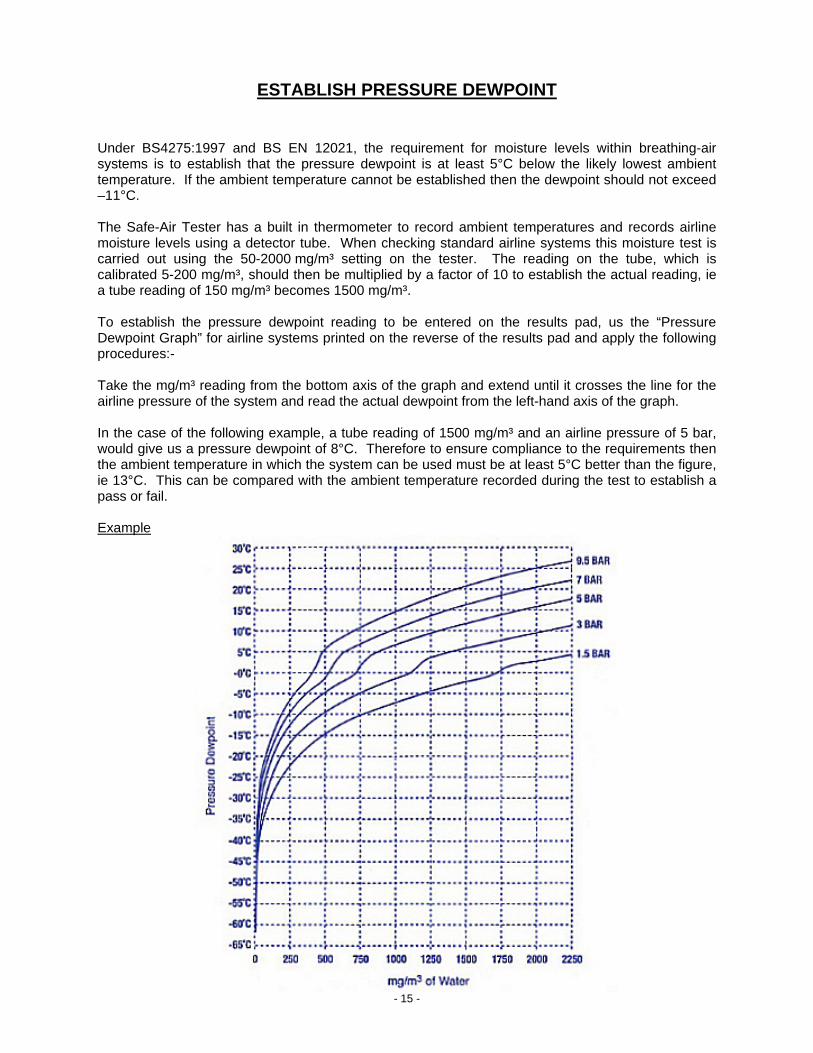
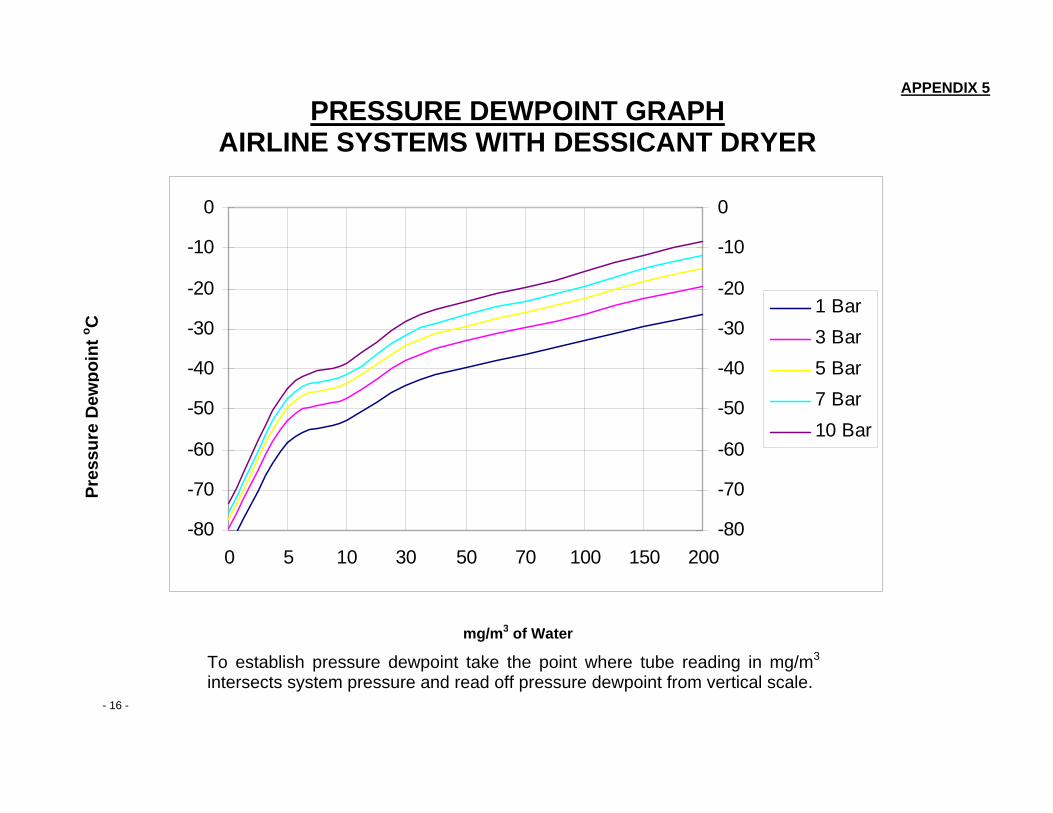
ESTABLISH PRESSURE DEWPOINT Under BS4275:1997 and BS EN 12021, the requirement for moisture levels within breathing-air systems is to establish that the pressure dewpoint is at least 5°C below the likely lowest ambient temperature. If the ambient temperature cannot be established then the dewpoint should not exceed –11°C. The Safe-Air Tester has a built in thermometer to record ambient temperatures and records airline moisture levels using a detector tube. When checking standard airline systems this moisture test is carried out using the 50-2000 mg/m³ setting on the tester. The reading on the tube, which is calibrated 5-200 mg/m³, should then be multiplied by a factor of 10 to establish the actual reading, ie a tube reading of 150 mg/m³ becomes 1500 mg/m³. To establish the pressure dewpoint reading to be entered on the results pad, us the “Pressure Dewpoint Graph” for airline systems printed on the reverse of the results pad and apply the following procedures:- Take the mg/m³ reading from the bottom axis of the graph and extend until it crosses the line for the airline pressure of the system and read the actual dewpoint from the left-hand axis of the graph. In the case of the following example, a tube reading of 1500 mg/m³ and an airline pressure of 5 bar, would give us a pressure dewpoint of 8°C. Therefore to ensure compliance to the requirements then the ambient temperature in which the system can be used must be at least 5°C better than the figure, ie 13°C. This can be compared with the ambient temperature recorded during the test to establish a pass or fail. Example
- 15 -
APPENDIX 5 PRESSURE DEWPOINT GRAPH
AIRLINE SYSTEMS WITH DESSICANT DRYER
- 16 -
Pres
sure
Dew
poin
t o C
mg/m3 of Water
-80
-70
-60
-50
-40
-30
-20
-10
0
0 5 10 30 50 70 100 150 200-80
-70
-60
-50
-40
-30
-20
-10
0
1 Bar3 Bar5 Bar7 Bar10 Bar
To establish pressure dewpoint take the point where tube reading in mg/m3 intersects system pressure and read off pressure dewpoint from vertical scale.
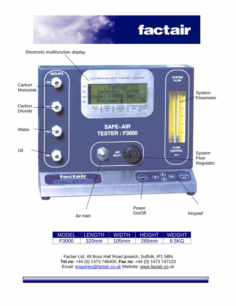
MODEL LENGTH WIDTH HEIGHT WEIGHT F3000 320mm 105mm 265mm 6.5KG
Factair Ltd, 49 Boss Hall Road,Ipswich, Suffolk, IP1 5BN Tel no: +44 (0) 1473 746400, Fax no: +44 (0) 1473 747123 Email: [email protected] Website: www.factair.co.uk