42
F400/500/650 HYUNDAI WIA Vertical Machining Center

F400/500/650HYUNDAI WIA Vertical Machining Center
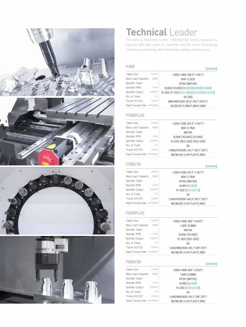
The Vertical Machining Center F400/500/650 Series, designed by Hyundai WIA with years of expertise and the latest technology, maximizes productivity while maintaining rigidity and accuracy.
Technical Leader
F500PLUSmm(in)
kg(lb)
-
r/min
kW(HP)
EA
mm(in)
m/min(ipm)
1,200×500 (47.2″×19.7″)
800 (1,764)
BBT40
8,000 [10,000] [12,000]
15 (20) [18.5 (25)] [18.5 (25)]
30
1,060/510/635 (41.7″/20.1″/25″)
36/36/30 (1,417/1,417/1,260)
Table Size
Max.Load Capacity
Spindle Taper
Spindle RPM
Spindle Output
No. of Tools
Travel (X/Y/Z)
Rapid Traverse Rate
F400mm(in)
kg(lb)
-
r/min
kW(HP)
EA
mm(in)
m/min(ipm)
1,000×460 (39.4″×18.1″)
600 (1,323)
BT40 [BBT40]
8,000 [12,000] [8,000] [8,000] [12,000]
15 (20) [11 (15)] [13.5 (18)] [15.8 (21)] [15.8 (21)]
24 [30]
800/460/520 (31.5″/18.1″/20.5″)
32/32/32 (1,260/1,260/1,260)
Table Size
Max.Load Capacity
Spindle Taper
Spindle RPM
Spindle Output
No. of Tools
Travel (X/Y/Z)
Rapid Traverse Rate
F500/50mm(in)
kg(lb)
-
r/min
kW(HP)
EA
mm(in)
m/min(ipm)
1,200×500 (47.2″×19.7″)
800 (1,764)
BT50 [BBT50]
6,000 [6,000]
15 (20) [27.8 (37.3)]
24
1,100/510/635 (43.3″/20.1″/25″)
36/36/30 (1,417/1,417/1,260)
Table Size
Max.Load Capacity
Spindle Taper
Spindle RPM
Spindle Output
No. of Tools
Travel (X/Y/Z)
Rapid Traverse Rate
F650PLUSmm(in)
kg(lb)
-
r/min
kW(HP)
EA
mm(in)
m/min(ipm)
1,600×650 (63″×25.6″)
1,300 (2,866)
BBT40
8,000 [10,000]
15 (20) [18.5 (25)]
30
1,400/660/635 (55.1″/26″/25″)
36/36/30 (1,417/1,417/1,260)
Table Size
Max.Load Capacity
Spindle Taper
Spindle RPM
Spindle Output
No. of Tools
Travel (X/Y/Z)
Rapid Traverse Rate
F650/50mm(in)
kg(lb)
-
r/min
kW(HP)
EA
mm(in)
m/min(ipm)
1,600×650 (63″×25.6″)
1,300 (2,866)
BT50 [BBT50]
6,000 [6,000]
15 (20) [27.8 (37.3)]
24
1,400/660/635 (55.1″/26″/25″)
36/36/30 (1,417/1,417/1,260)
Table Size
Max.Load Capacity
Spindle Taper
Spindle RPM
Spindle Output
No. of Tools
Travel (X/Y/Z)
Rapid Traverse Rate
[SIEMENS]
[SIEMENS]
[SIEMENS]
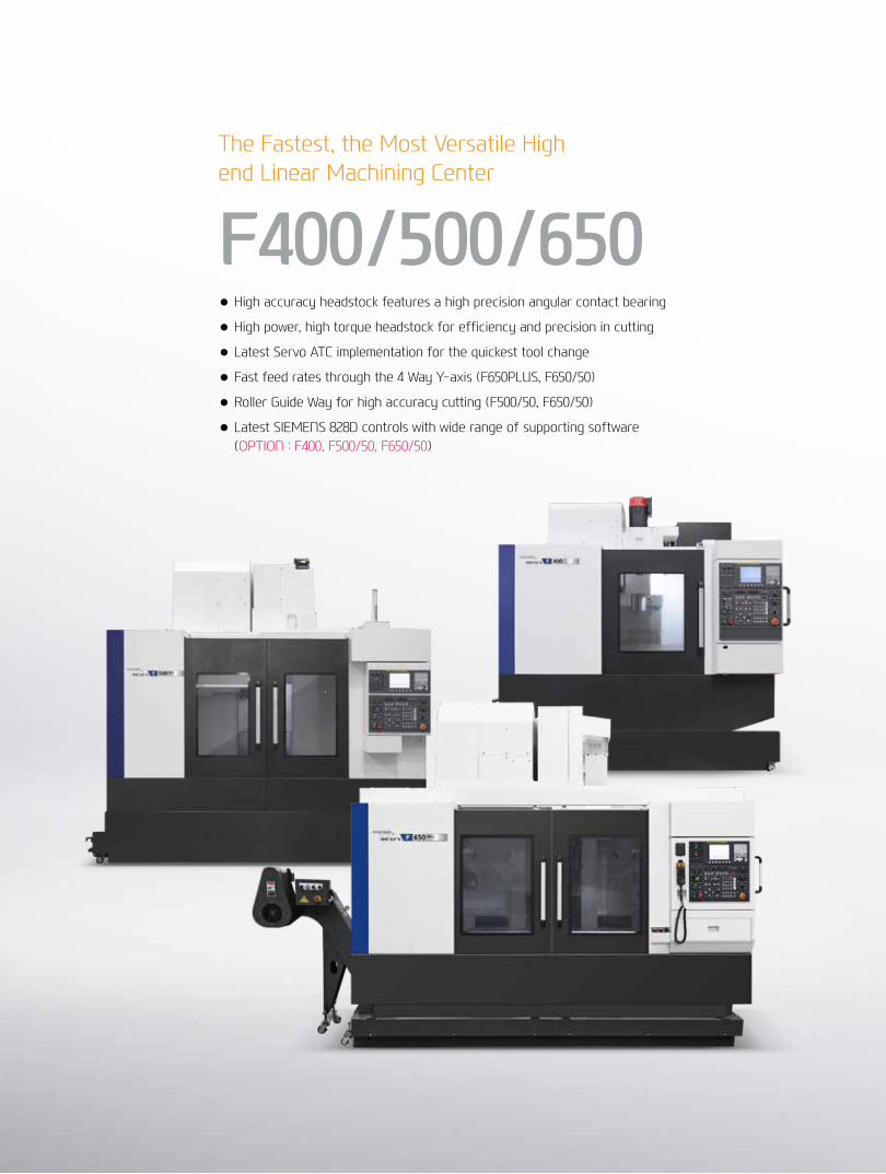
The Fastest, the Most Versatile High end Linear Machining Center
F400/500/650● High accuracy headstock features a high precision angular contact bearing
● High power, high torque headstock for efficiency and precision in cutting
● Latest Servo ATC implementation for the quickest tool change
● Fast feed rates through the 4 Way Y-axis (F650PLUS, F650/50)
● Roller Guide Way for high accuracy cutting (F500/50, F650/50)
● Latest SIEMENS 828D controls with wide range of supporting software (OPTION : F400, F500/50, F650/50)

01 F400 Basic FeaturesHigh Speed & Productivity Vertical Machining Center
F400/500/650
Direct SpindleThe directly coupled spindle at a max rev of 12,000rpm, allows high speed machining. Additionally, the large diameter and the thickness of the spindle add stability to the machine.
Table & Machining Area
Double Anchored BallscrewIn order to eliminate thermal growth and increase accuracy, all axis are driven by high precision double anchored ballscrews. The pretensioned and double anchored design provides outstanding positioning and repeatability with virtually no thermal growth.
Directly Coupled Servo MotorThe ballscrews are directly coupled to the servo motor. This eliminates the need for any transmission parts, which may impact machine accuracy and efficiency.
03
01
02
460(18.1″)
460(18.1″)
635(25″)
150(5.9″)
100(3.93″)
800(31.4″)
100(3.93″)
600 kg (1,323 lb)
◉ Table Size (X/Y axis) : 1,000/460 mm (39.3″/18.1″)

04+
05
F4
00/5
00/6
50Ve
rtic
al M
achi
ning
Cen
ter
HYU
ND
AI W
IAM
ACH
INE
TOO
L
Basic Features
01
03
02
◉ Spindle Speed : 8,000 [8,000] [12,000] [8,000] [12,000] rpm
◉ Spindle Output (Max./Cont.) : 15/11 [15/11] [11/7.5] [13.5/9] [15.8/10.5] kW
(20/14.7 [20/15] [15/10] [18/12] [21/14] HP)
◉ Spindle Torque (Max./Cont.) : 95/70 [95/70] [70/45] [95/63] [95/63] N.m
(70/51.6 [70/51.6] [51.6/33.2] [70/46.5] [70/46.5] lbf.ft)
◉ Rapid Traverse Rate (X/Y/Z axis) :
32/32/32 m/min (1,260/1,260/1,260 ipm)
◉ Travel (X/Y/Z axis) :
800/460/520 mm (31.5″/18.1″/20.4″)
[SIEMENS]
High precision & High speed Vertical Machining Center

02 F500PLUS Basic FeaturesHigh Speed & Productivity Vertical Machining Center
F400/500/650
Roller Type LM GuideDue to the rigidity of the linear roller guide, the feed rates on the F500PLUS are fast and reduce cutting time.
Table & Machining Area
Double Anchored BallscrewIn order to eliminate thermal growth and increase accuracy, all axis are driven by high precision double anchored ballscrews. The pretensioned and double anchored design provides outstanding positioning and repeatability with virtually no thermal growth.
Directly Coupled Servo MotorThe ballscrews are directly coupled to the servo motor. This eliminates the need for any transmission parts, which may impact machine accuracy and efficiency.
03
02
01
500(19.6″)
150(5.9″)
70(2.7″)
70(2.7″)
1060 (41.7″)
500(19.6″)
800 kg (1,764 lb)
◉ Table Size (X/Y axis) : 1,200/500 mm (47.2″/19.6″)
635(25″)

High precision & High speed Vertical Machining Center◉ Spindle Speed F500 PLUS : 8,000 [10,000] [12,000] rpm F500/50 : 6,000 [6,000] rpm
◉ Spindle Output (Max./Cont.) F500PLUS : 15/11 [18.5/15] [18.5/11] kW (20/15 [24.8/20][24.8/15] HP)
F500/50 : 15/11[27.8/18.5] kW (20/15 [37.3/24.8] HP)
◉ Spindle Torque (Max./Cont.) F500PLUS : 286/143 [117.6/95.3] [117.7/70] N.m
(211/105.5 [86.7/70.3] [70.3/51.6] lbf.ft)
F500/50 : 358/179 [294/196] N.m (264/132 [216.8/97.4] lbf.ft)
06+
07
F4
00/5
00/6
50Ve
rtic
al M
achi
ning
Cen
ter
HYU
ND
AI W
IAM
ACH
INE
TOO
L
Basic Features
01
02
03
Solid Body High ColumnHigh column of 150mm(5.9") and 300mm(11.8") is provided.
◉ Rapid Traverse Rate (X/Y/Z axis) :
36/36/30 m/min (1,417/1,417/1,260 ipm)
◉ Travel (X/Y/Z axis)
F500 Plus : 1,060/510/635 mm (41.7″/20″/25″)
F500/50 : 1,100/510/635 mm (43.3″/20″/25″)
[SIEMENS]

03 F650PLUS Basic FeaturesHigh Speed & Productivity Vertical Machining Center
F400/500/650
4 WAY Y-axisThe 4 slide ways on Y-axis eliminate overhang and increase accuracy throughout the full extent of travel.
Table & Machining Area
Double Anchored Ball ScrewIn order to eliminate thermal growth and increase accuracy, all axis are driven by high precision double anchored ballscrews. The pretensioned and double anchored design provides outstanding positioning and repeatability with virtually no thermal growth.
Directly Coupled Servo MotorThe ballscrews are directly coupled to the servo motor. This eliminates the need for any transmission parts, which may impact machine accuracy and efficiency.
04
0302
01
Roller Type LM GuideDue to the rigidity of the linear roller guide, the feed rates on the F650PLUS are fast and reduce cutting time.
650(25.6″)
1,400(55.1″)
650(25.6″)1,300 kg (2,866 lb)
◉ Table Size (X/Y axis) : 1,600/650 mm (63″/25.6″)
635(25″)
150(5.9″)
100(3.93″)
100(3.93″)

High precision & High speed Vertical Machining Center◉ Spindle Speed F650PLUS : 8,000 [10,000] rpm F650/50 : 6,000 [6,000] rpm
◉ Spindle Output (Max./Cont.) F650PLUS : 15/11 [18.5/15] kW (20/15 [24.8/20] HP)
F650/50 : 15/11 [27.8/18.5] kW (20/15 [37.3/24.8] HP)
◉ Spindle Torque (Max./Cont.) F650PLUS : 286/143 [117.6/95.3] N.m (211/105.5 [86.7/70.3] lbf.ft)
F650/50 : 358/179 [294/196] N.m (264/132 [216.8/97.4] lbf.ft)
08+
09
F4
00/5
00/6
50Ve
rtic
al M
achi
ning
Cen
ter
HYU
ND
AI W
IAM
ACH
INE
TOO
L
Basic Features
01
03
04
02
Solid Body High ColumnHigh column of 300mm(11.8") is provided.
◉ Rapid Traverse Rate (X/Y/Z axis) :
36/36/30 m/min (1,417/1,417/1,260 ipm)
◉ Travel (X/Y/Z axis) : 1,400/660/635 mm (55.1″/25.9″/25″)
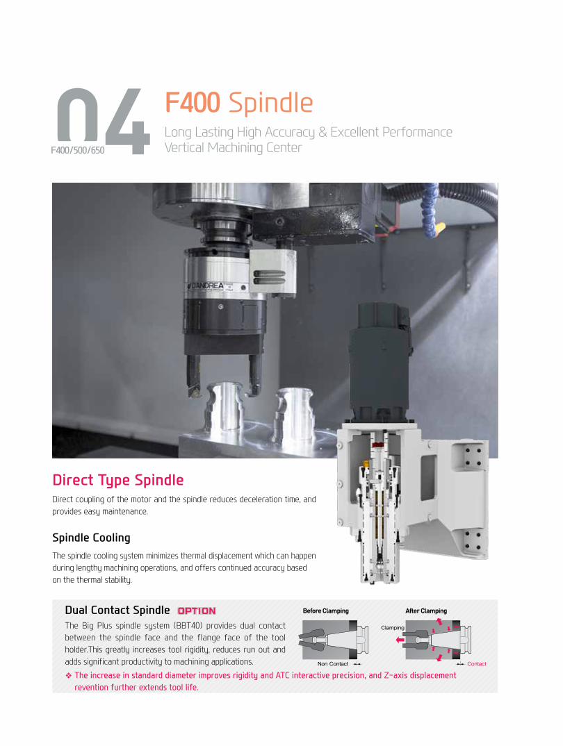
Spindle CoolingThe spindle cooling system minimizes thermal displacement which can happen during lengthy machining operations, and offers continued accuracy based on the thermal stability.
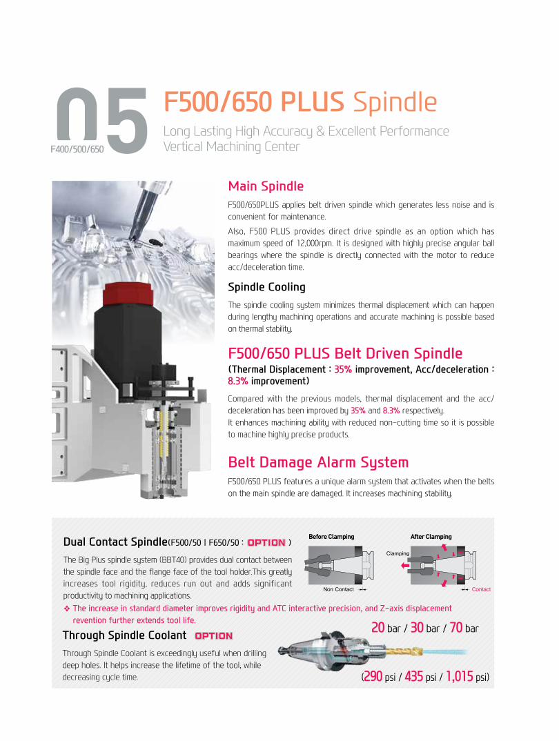
Dual Contact SpindleThe Big Plus spindle system (BBT40) provides dual contact between the spindle face and the flange face of the tool holder.This greatly increases tool rigidity, reduces run out and adds significant productivity to machining applications.
❖ The increase in standard diameter improves rigidity and ATC interactive precision, and Z-axis displacement revention further extends tool life.
Before Clamping After Clamping
Clamping
Non Contact Contact
Axial Movement is Important for Face Contact
04 F400 SpindleLong Lasting High Accuracy & Excellent PerformanceVertical Machining CenterF400/500/650
Direct Type SpindleDirect coupling of the motor and the spindle reduces deceleration time, and provides easy maintenance.
Spindle
10+
11
F4
00/5
00/6
50Ve
rtic
al M
achi
ning
Cen
ter
HYU
ND
AI W
IAM
ACH
INE
TOO
L
Power (kW) Torque (N.m)
0
15.8[21]
10.5[14.8]
95[70]
63[46.5]
8,0004,0002,000
Spindle Speed (r/min)
15.8kW[21HP] (S6-40%)
95N∙m[70lbf∙ft] (S6-40%)
10.5kW[14.8HP] (Cont.)
63N∙m[46.5lbf∙ft] (Cont.)
Power (kW[HP]) Torque (N∙m[lbf∙ft])
0
15[20]
11[14.7] 95[70]
70[51.6]
8,0003,5001,500
15kW[20HP] (30min)
95N∙m[70lbf∙ft] (30min) 11kW[14.7HP] (Cont.)
70N∙m[51.6lbf∙ft] (Cont.)
Power (kW[HP]) Torque (N∙m[lbf∙ft])
0
11[14.7]
7.5[10] 70[51.6]
47[33.2]
12,0007,0001,500
11kW[14.7HP] (30min)
70N∙m[51.6lbf∙ft] (30min) 7.5kW[10HP] (Cont.)
45N∙m[33.2lbf∙ft] (Cont.)
Spindle Speed (r/min)
Spindle Speed (r/min)
Power (kW[HP]) Torque (N∙m[lbf∙ft])
0
16[21.4]
11[14.7]
95[70]
63[46.5]
8,0003,500 4,500500 1,500
Spindle Speed (r/min)
13.5kW[18.1HP] (30min)
95N∙m[70lbf∙ft] (30min)
9kW[12HP] (Cont.)
63N∙m[46.5lbf∙ft] (Cont.)
Power (kW[HP]) Torque (N∙m[lbf∙ft])
0
15.8[21]
10.5[14.8]
95[70]
63[46.5]
12,0004,000500 2,000
Spindle Speed (r/min)
15.8kW[21HP] (30min)
95N∙m[70lbf∙ft] (30min)
10.5kW[14.8HP] (Cont.)
63N∙m[46.5lbf∙ft] (Cont.)
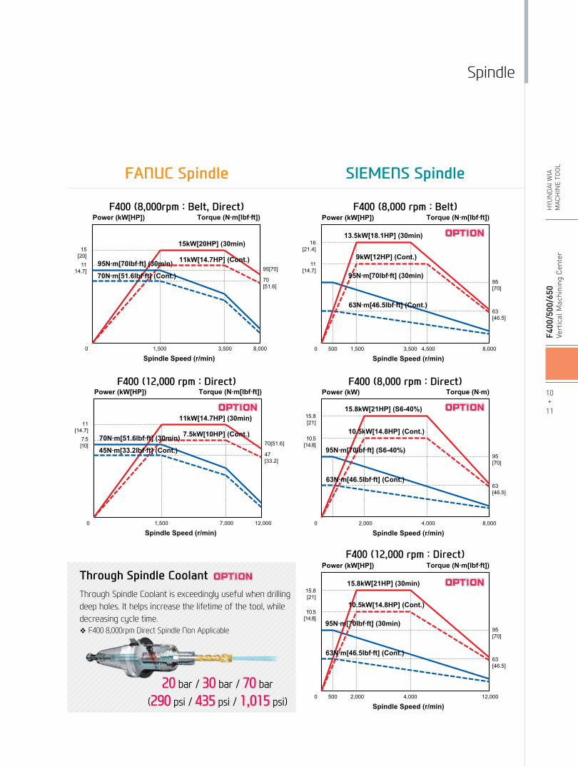
FANUC Spindle SIEMENS Spindle
Through Spindle CoolantThrough Spindle Coolant is exceedingly useful when drilling deep holes. It helps increase the lifetime of the tool, while decreasing cycle time.❖ F400 8,000rpm Direct Spindle Non Applicable
20 bar / 30 bar / 70 bar
(290 psi / 435 psi / 1,015 psi)
F400 (8,000rpm : Belt, Direct)
F400 (12,000 rpm : Direct)
F400 (8,000 rpm : Belt)
F400 (8,000 rpm : Direct)
F400 (12,000 rpm : Direct)
05 F500/650 PLUS SpindleLong Lasting High Accuracy & Excellent PerformanceVertical Machining CenterF400/500/650
Through Spindle CoolantThrough Spindle Coolant is exceedingly useful when drilling deep holes. It helps increase the lifetime of the tool, while decreasing cycle time.
20 bar / 30 bar / 70 bar
Dual Contact Spindle(F500/50 | F650/50 : )
The Big Plus spindle system (BBT40) provides dual contact between the spindle face and the flange face of the tool holder.This greatly increases tool rigidity, reduces run out and adds significant productivity to machining applications.❖ The increase in standard diameter improves rigidity and ATC interactive precision, and Z-axis displacement
revention further extends tool life.
Before Clamping After Clamping
Clamping
Non Contact Contact
Axial Movement is Important for Face Contact
(290 psi / 435 psi / 1,015 psi)
Main SpindleF500/650PLUS applies belt driven spindle which generates less noise and is convenient for maintenance.
Also, F500 PLUS provides direct drive spindle as an option which has maximum speed of 12,000rpm. It is designed with highly precise angular ball bearings where the spindle is directly connected with the motor to reduce acc/deceleration time.
Spindle CoolingThe spindle cooling system minimizes thermal displacement which can happen during lengthy machining operations and accurate machining is possible based on thermal stability.
F500/650 PLUS Belt Driven Spindle(Thermal Displacement : 35% improvement, Acc/deceleration : 8.3% improvement)
Compared with the previous models, thermal displacement and the acc/deceleration has been improved by 35% and 8.3% respectively. It enhances machining ability with reduced non-cutting time so it is possible to machine highly precise products.
Belt Damage Alarm SystemF500/650 PLUS features a unique alarm system that activates when the belts on the main spindle are damaged. It increases machining stability.

Power (kW[HP]) Torque (N∙m[lbf∙ft])
Spindle Speed (r/min)0
15[20]
11[14.7]
7.5[10]
286[211]
95[70]
18[13.3]9[6.6]
143[105.5]
8,0006,000500 750
15kW[20HP] (30min)
11kW[14.7HP] (Cont.)
Power (kW[HP]) Torque (N∙m[lbf∙ft])
Spindle Speed (r/min)0
15[20]
11[14.7]
18.5[24.8] 117.6
[86.7]
95.3[70.3]
12,00010,0001,500
Power (kW[HP]) Torque (N∙m[lbf∙ft])
Spindle Speed (r/min)0
15[20]
11[14.7]
7.5[10]
358[264]
179[132]
6,0004,800400 600
358N∙m[264lbf∙ft] (30min)
179N∙m[132lbf∙ft] (Cont.)
Power (kW[HP]) Torque (N∙m[lbf∙ft])
Spindle Speed (r/min)0
15[20]
18.5[24.8] 117.6
[86.7]
95.3[70.3]
10,0001,50035
18.5kW[24.8HP] (30min)
15kW[20HP] (Cont.)
117.6N∙m[86.7lbf∙ft] (30min)
95.3N∙m[70.3lbf∙ft] (Cont.)
286N∙m[211lbf∙ft] (30min)
143N∙m[105.5lbf∙ft] (Cont.)
15kW[20HP] (30min)11kW[14.7HP] (Cont.)
18.5kW[24.8HP] (S3 25%)
15kW[20HP] (S3 60%)
11kW[14.7HP] (Cont.)
117.7N∙m[86.8lbf∙ft] (S3 25%)
95.5N∙m[70.4lbf∙ft] (S3 60%)
70N∙m[51.6lbf∙ft] (Cont.)
Power (kW[HP]) Torque (N∙m[lbf∙ft])
Spindle Speed (r/min)0
27.8[37.3]
18.5[24.8] 294
[216.8]
196[144.5]
6,0004,0001,500
27.8kW[37.3HP] (S6-40%)
18.5kW[24.8HP] (Cont.)294N.m[216.8lbf∙ft] (S6-40%)
196N.m[144.5lbf∙ft] (Cont.)
F500/50, F650/50 (6,000 rpm Belt)The 1PH8 Series is a high quality performance motor providing concentricity of 10㎛ and fast response time. They operate smoothly in extreme environments such as high temperature, dust and dirt. Heat emission minimizing design makes it possible to maintain a degree of accuracy at all time.
1PH8 Spindle Motor
12+
13
F4
00/5
00/6
50Ve
rtic
al M
achi
ning
Cen
ter
HYU
ND
AI W
IAM
ACH
INE
TOO
L
Spindle
Power (kW[HP]) Torque (N∙m[lbf∙ft])
Spindle Speed (r/min)0
15[20]
11[14.7]
7.5[10]
286[211]
95[70]
18[13.3]9[6.6]
143[105.5]
8,0006,000500 750
15kW[20HP] (30min)
11kW[14.7HP] (Cont.)
Power (kW[HP]) Torque (N∙m[lbf∙ft])
Spindle Speed (r/min)0
15[20]
11[14.7]
18.5[24.8] 117.6
[86.7]
95.3[70.3]
12,00010,0001,500
Power (kW[HP]) Torque (N∙m[lbf∙ft])
Spindle Speed (r/min)0
15[20]
11[14.7]
7.5[10]
358[264]
179[132]
6,0004,800400 600
358N∙m[264lbf∙ft] (30min)
179N∙m[132lbf∙ft] (Cont.)
Power (kW[HP]) Torque (N∙m[lbf∙ft])
Spindle Speed (r/min)0
15[20]
18.5[24.8] 117.6
[86.7]
95.3[70.3]
10,0001,50035
18.5kW[24.8HP] (30min)
15kW[20HP] (Cont.)
117.6N∙m[86.7lbf∙ft] (30min)
95.3N∙m[70.3lbf∙ft] (Cont.)
286N∙m[211lbf∙ft] (30min)
143N∙m[105.5lbf∙ft] (Cont.)
15kW[20HP] (30min)11kW[14.7HP] (Cont.)
18.5kW[24.8HP] (S3 25%)
15kW[20HP] (S3 60%)
11kW[14.7HP] (Cont.)
117.7N∙m[86.8lbf∙ft] (S3 25%)
95.5N∙m[70.4lbf∙ft] (S3 60%)
70N∙m[51.6lbf∙ft] (Cont.)
Power (kW[HP]) Torque (N∙m[lbf∙ft])
Spindle Speed (r/min)0
27.8[37.3]
18.5[24.8] 294
[216.8]
196[144.5]
6,0004,0001,500
27.8kW[37.3HP] (S6-40%)
18.5kW[24.8HP] (Cont.)294N.m[216.8lbf∙ft] (S6-40%)
196N.m[144.5lbf∙ft] (Cont.)
F500/650 PLUS (8,000 rpm Belt)
F500 PLUS (12,000 rpm Direct)
F500/650 PLUS (10,000 rpm Belt)
F500/50, F650/50 (6,000 rpm Belt)
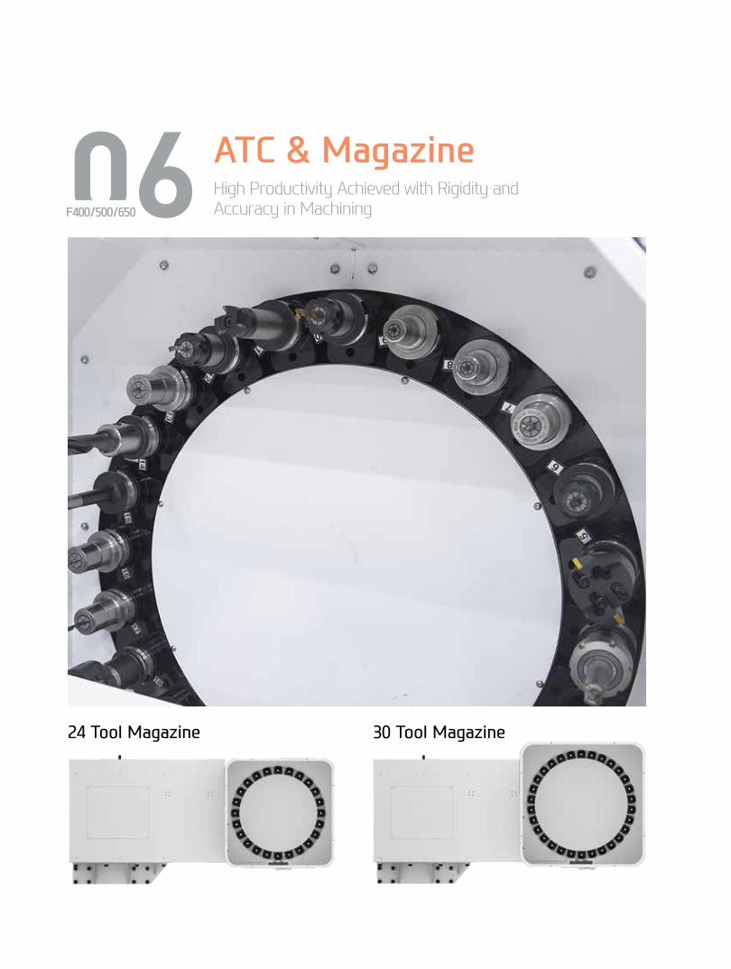
06 ATC & MagazineHigh Productivity Achieved with Rigidity and Accuracy in MachiningF400/500/650
24 Tool Magazine 30 Tool Magazine
14+
15
F4
00/5
00/6
50Ve
rtic
al M
achi
ning
Cen
ter
HYU
ND
AI W
IAM
ACH
INE
TOO
L
Peripheral Device
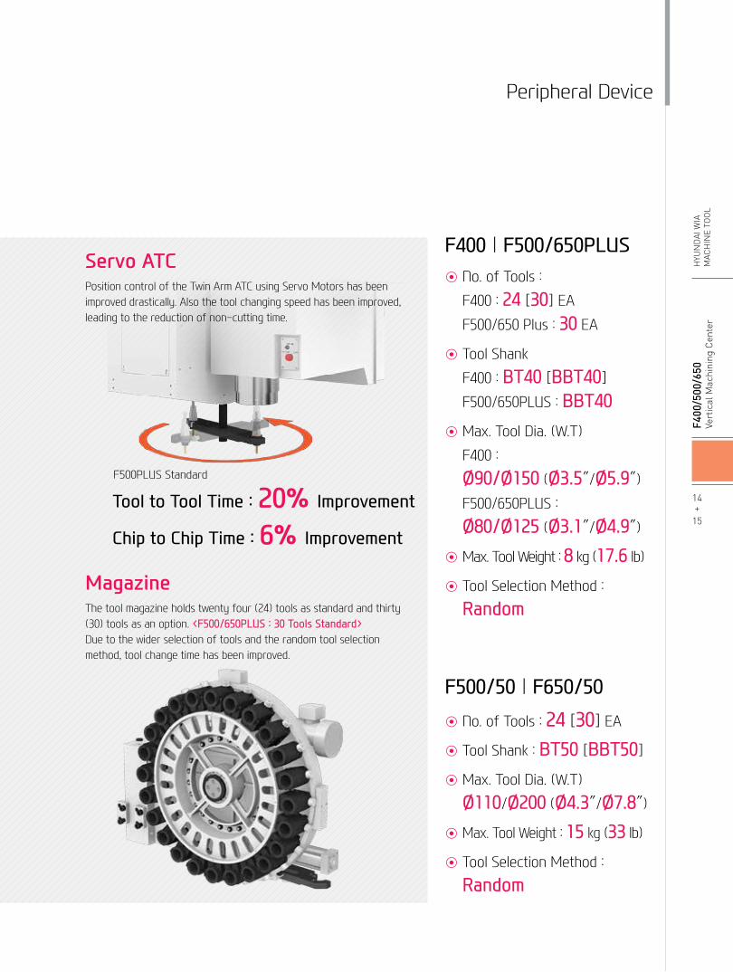
MagazineThe tool magazine holds twenty four (24) tools as standard and thirty (30) tools as an option. <F500/650PLUS : 30 Tools Standard>Due to the wider selection of tools and the random tool selection method, tool change time has been improved.
◉ No. of Tools :
F400 : 24 [30] EA
F500/650 Plus : 30 EA
◉ Tool Shank
F400 : BT40 [BBT40]
F500/650PLUS : BBT40◉ Max. Tool Dia. (W.T)
F400 :
Ø90/Ø150 (Ø3.5″/Ø5.9″)
F500/650PLUS :
Ø80/Ø125 (Ø3.1″/Ø4.9″)
◉ Max. Tool Weight : 8 kg (17.6 lb)
◉ Tool Selection Method :
Random
◉ No. of Tools : 24 [30] EA
◉ Tool Shank : BT50 [BBT50]
◉ Max. Tool Dia. (W.T)
Ø110/Ø200 (Ø4.3″/Ø7.8″)
◉ Max. Tool Weight : 15 kg (33 lb)
◉ Tool Selection Method :
Random
F400 | F500/650PLUS
F500/50 | F650/50
Servo ATCPosition control of the Twin Arm ATC using Servo Motors has been improved drastically. Also the tool changing speed has been improved, leading to the reduction of non-cutting time.
Tool to Tool Time : 20% Improvement
Chip to Chip Time : 6% Improvement
F500PLUS Standard

07 Machining CapabilityHigh Performance, High Accuracy CuttingVertical Machining CenterF400/500/650
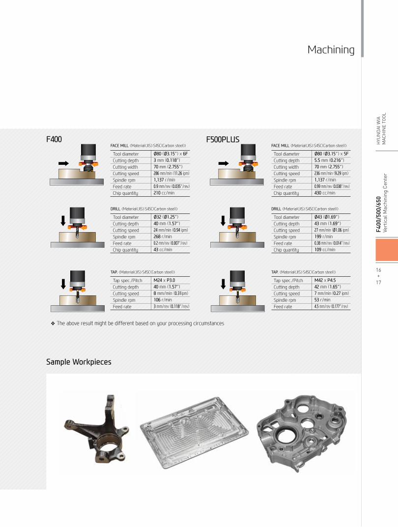
Machining
❖ The above result might be different based on your processing circumstances
16+
17
F4
00/5
00/6
50Ve
rtic
al M
achi
ning
Cen
ter
HYU
ND
AI W
IAM
ACH
INE
TOO
L
FACE MILL 〈Material〈JIS〉:S45C(Carbon steel)〉
Tool diameterCutting depthCutting widthCutting speedSpindle rpmFeed rateChip quantity
Ø80 (Ø3.15″) x 5F5.5 mm (0.216″)70 mm (2.755″)236 mm/min (9.29 ipm)1,137 r/min0.99 mm/rev (0.038″/rev)430 cc/min
DRILL 〈Material〈JIS〉:S45C(Carbon steel)〉
Tool diameterCutting depthCutting speedSpindle rpmFeed rateChip quantity
Ø43 (Ø1.69″)43 mm (1.69″)27 mm/min (Ø1.06 ipm)199 r/min0.38 mm/rev (0.014″/rev)109 cc/min
TAP. 〈Material〈JIS〉:S45C(Carbon steel)〉
Tap spec./PitchCutting depthCutting speedSpindle rpmFeed rate
M42 x P4.542 mm (1.65″)7 mm/min (0.27 ipm)53 r/min4.5 mm/rev (0.177″/rev)
F400 F500PLUS FACE MILL 〈Material〈JIS〉:S45C(Carbon steel)〉
Tool diameterCutting depthCutting widthCutting speedSpindle rpmFeed rateChip quantity
Ø80 (Ø3.15″) x 6F3 mm (0.118″)70 mm (2.755″)286 mm/min (11.26 ipm)1,137 r/min 0.9 mm/rev (0.035″/rev)210 cc/min
DRILL 〈Material〈JIS〉:S45C(Carbon steel)〉
Tool diameterCutting depthCutting speedSpindle rpmFeed rateChip quantity
Ø32 (Ø1.25″)40 mm (1.57″)24 mm/min (0.94 ipm)268 r/min0.2 mm/rev (0.007″/rev)43 cc/min
TAP. 〈Material〈JIS〉:S45C(Carbon steel)〉
Tap spec./PitchCutting depthCutting speedSpindle rpmFeed rate
M24 x P3.040 mm (1.57″)8 mm/min (0.31ipm)106 r/min3 mm/rev (0.118″/rev)
Sample Workpieces

Intelligent Machining
Machine Monitoring
High Precision
High Productivity Energy Savin
g
HW-TM | HW-MCS | HW-A
FC
HW-TOM | HW-WCM
HW-ESS
User Friendly
HW-MMSHW-TDC | HW
-WARM
UP
HYUNDAI WIA Smart System for Vertical Machining Center
User Convenience
HW-eDNC
HW-MCG
Faster processing and enhanced accuracy in are possiblethrough the HYUNDAI WIA Smart System. The user friendly software and equipment monitoring of the Smart System maximizes productivity.
HW-eDNCHYUNDAI WIA ethernet Direct Numerical Control
This software allows transmition of NC data between PC and a machine's CNC. The processing programs can be managed on the PC through the ethernet or serial communication.
HW-MMSHYUNDAI WIAMachine Monitoring System
This software is for remote control monitoring of equipment status (mobile, PC.) It checks and manages the state of multiple machines and the progress of processing on a real time basis.
08 Smart SystemSoftware for smart operating and machiningF400/500/650

HYUNDAI WIA Smart System
USB PortConvenience is increased when inputting and outputting program. The USB port is available in addition to the former input output methods such as CF memort card and LAN.(HW F Series, S 828D : Standard / F32i-A : Non applicable)
18+
19
F4
00/5
00/6
50Ve
rtic
al M
achi
ning
Cen
ter
HYU
ND
AI W
IAM
ACH
INE
TOO
L
HW-TDCHYUNDAI WIA Thermal Displacement Compensation
Software that measures the changes in the external environment as well as heat emission during processing to help reduce thermal displacement.
HW-ESSHYUNDAI WIAEnergy Saving System
An environmental friendly software that reduces the unnecessarily wasted standby power waiting for an operation.
(FANUC)
HW-TMHYUNDAI WIATool Monitoring
A tool monitoring software which analyzes the load of the spindle motor to determine and monitor possible damage of tools.
(FANUC)
HW-MCGHYUNDAI WIAMachine Guidance
Software that offers operation, maintenance, management monitoring and various user friendly features.
(FANUC)
HW-WARMUPHYUNDAI WIAWARMing Up
Warm-up software that measures main spindle halt and offers system warm-up time automatically.
HW-TOMHYUNDAI WIATool Offset Measurement
User friendly GUI software that indicates tool length, diameter, and damage (H/W excluded)
(FANUC)
HW-WCMHYUNDAI WIA Work Coordinate Measurement
User-friendly GUI software that measures work coordinates (H/W excluded )
(FANUC)
HW-AFCHYUNDAI WIAAdaptive Feed Control
Software that controls the feed automatically to maintain a certain working load to extend tool life as well as productivity.
(FANUC)
HW-MCSHYUNDAI WIAMachining Condition Selection
Software that automatically sets cutting and feeding parameters according to the machining types (speed, degree, quality)
(FANUC)

DIFFERENTIATED CAPABILITIES, INTEGRATED ENGINEERING PERFECTLY INTERLINKEDSIEMENS 828D is a latest model CNC. It is designed for horizontal/vertical all-purpose equipment.
Its 80-bit control reduces processing time and increases productivity. The 828D is easy to maintain and run, with its easy setup functions.
09 SIEMENS ControllerSoftware for smart operating and machining
F400/500/650

• Dialogue-type programming, simple and convenient
• Effective specifications for small quantity batch production
• Step-by-step operation possible without knowledge of the DIN/ISO code
Shop Mill
• 3D confirmation of the completed processing configuration of the NC program is possible.
•Offers standards for 2D simulation.• Possible to confirm the simulation of the
NC grogram during processing.
3D Simulation
• Easy to install/uninstall an option (Ex : barfeeder and chip conveyor, etc.)
• Possible to install in one motion without revision of individual perimeters.
• A spate list is unnecessary as option items are indicated with letters.
Easy Extend
Easy input/output of a program is possible as a USB memory card, a CF memory card and LAN can all be used.
Variable Communication Port
RJ 45 Ethernet
USB 2.0
Compact Flash Card
If the ISO Dialect (G291) is ordered, JIS-based G-code programs can be used. (Standard)
SIEMENS Technology SIEMENS Communication
ISO CodeProgramming
SIEMENS 828D comes with Advanced Surface, metal processing software that monitors speed and accuracy.
20+
21
F4
00/5
00/6
50Ve
rtic
al M
achi
ning
Cen
ter
HYU
ND
AI W
IAM
ACH
INE
TOO
L
SIEMENS
SIEMENS Advanced Surface
Speed
Speed
SINUMERIK + SINAMICS 80bit NANO FP Accuracy
Machining Time Time : 48 min
Unblanced Velocity
Machining Time Time : 33 min
Blanced Velocity
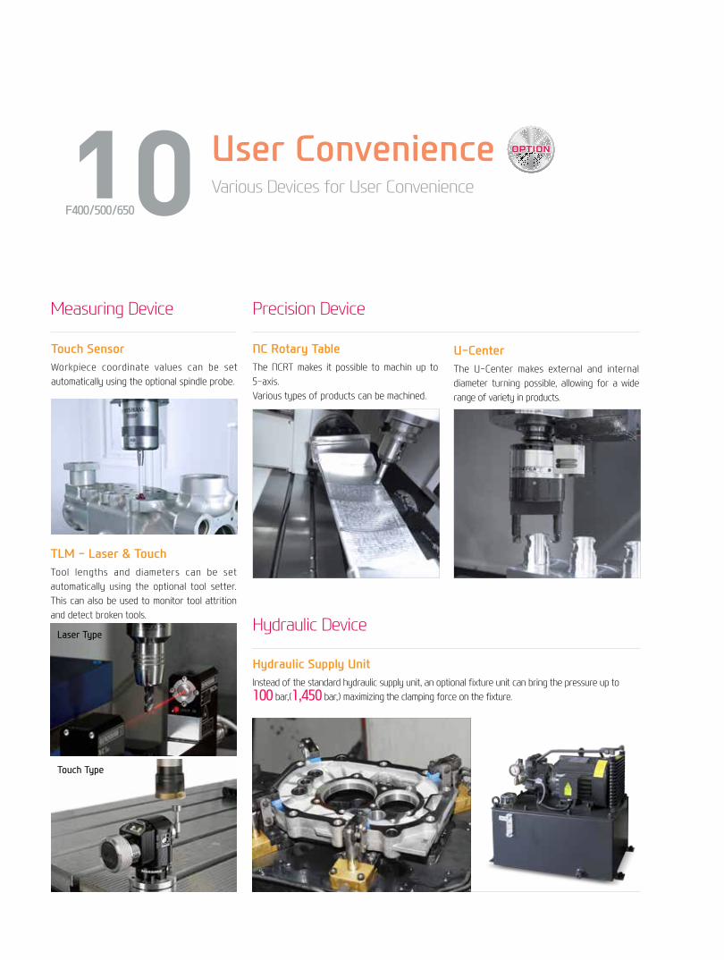
User ConvenienceVarious Devices for User Convenience
Hydraulic Supply UnitInstead of the standard hydraulic supply unit, an optional fixture unit can bring the pressure up to 100 bar,(1,450 bar,) maximizing the clamping force on the fixture.
NC Rotary TableThe NCRT makes it possible to machin up to 5-axis.Various types of products can be machined.
U-CenterThe U-Center makes external and internal diameter turning possible, allowing for a wide range of variety in products.
Measuring Device
Hydraulic Device
Precision Device
10F400/500/650
Touch SensorWorkpiece coordinate values can be set automatically using the optional spindle probe.
TLM - Laser & TouchTool lengths and diameters can be set automatically using the optional tool setter. This can also be used to monitor tool attrition and detect broken tools.
Laser Type
Touch Type

Optional
•Hinge Belt Type : Highly efficient when disposing a lot of chips. Capable of handling stringy chips. (Long Chip)
•Scraper Type : Convenient for shortly cut chips.. (Short Chip)•Drum Filter Type : Advantageous in precision, as the chips do not flow in to the coolant nozzle. (AL Chip)
Timely and effective disposal of chips will enhance productivity as well as the working environment.
22+
23
F4
00/5
00/6
50Ve
rtic
al M
achi
ning
Cen
ter
HYU
ND
AI W
IAM
ACH
INE
TOO
L
Chip Conveyor Front (Left)
Chip Conveyor Rear (Left)
Chip Conveyor
Gantry Loader SystemImplementation of high speed gantry loaders is possible as well as the construction of flexible automation cells by a work stocker. Optimization of the installation space is also possible.
Work Stocker
Chip Disposal Process (F500PLUS)
Std. Coolant (Nozzle)
Bed Flushing Coolant
Through Spindle Coolant
(20/30/70 bar [290/435/1,015 psi)
Jet Coolant
Gun Coolant
Side Oil Hole Coolant
Standard
Standard
Option
Option
Option
Option
Coolant Unit (F500/650PLUS Std.)

F400○○○
●☆☆
●○○●○●●○-○●○●○○○○○○☆○○○○
○○○○○☆○☆
○○○○☆
○☆-☆○☆○☆○☆○○
●
○○○☆
Work Coordinate Measurement (HW-WCM) : FANUCMachining Condition Selection (HW-MCS) : FANUCAdaptive Feed Control (HW-AFC) : FANUCETCTool BoxCustomized ColorCAD & CAM SoftwareElectric DeviceCall LightCall LightCall Light & BuzzerWork LightElectric Cabinet LightDoor Inter-LockRemote MPG
3 Axis MPG
Spindle Load Meter
Spindle RPM Meter
Work CounterTotal CounterTool Counter
Multi Tool Counter
Electric Circuit BreakerAVR (Auto Voltage Regulator)TransformerFlash Memory CardAuto Power OffBack up Module for Black outMeasuring Device
Air Zero
Work Measuring DeviceTLM(Marposs/Renishaw/Bloom)Tool Broken Detective DeviceLinear ScaleCoolant Level Sensor (Only for Chip Conveyor)EnvironmentAir ConditionerDehumidifierOil Mist CollectorOil Skimmer (Only for Chip Conveyor)MQL (Minimal Quantity Lubrication)Fixture & Automation
Auto Door
Auto Shutter (Only for Automatic System)Sub O/P
NC Rotary TableI/F
Control of Additional Axis
External M Code 4eaAutomation Interface
I/O Extension (In & Out)
Hyd. Device
Std. Hyd. Unit
Hyd. Unit for Fixture
Need Munsel No.
1 Color : ■3 Color : ■■■3 Color : ■■■B
FANUCSIEMENSFANUC (Mounted Type)SIEMENS (Built-in Type)FANUC (Mounted Type)SIEMENS (Built-in Type)DigitalDigitalDigital6ea9ea
25kVA
TACOSMC
TouchLaser
X/Y/Z Axis
Std.High Speed
SingleChannel1Axis2Axis
16Contact32Contact
65bar (942.7 psi) / 20ℓ(5.3 gal)45bar (652.7 psi)70bar (1,015 psi)100bar (1,450 psi)Customized
Standard & Optional
8,000rpm (Direct)8,000rpm (Belt)8,000rpm (Belt)8,000rpm (Direct)12,000rpm (Direct)12,000rpm (Direct)
Spindle Cooling System
ATC
ATC Extension
Tool Shank Type
U-Center
Stud Bolt Collet Change
Table & ColumnAPCTap Type PalletT-Slot PalletNC Rotary TableHigh ColumnCoolant SystemStd. Coolant (Nozzle)Bed Flushing Coolant
Through spindle coolant*
Top CoverJet CoolantGun CoolantSide Oil Hole CoolantAir GunCutting Air BlowTool Measuring Air Blow (Only for TLM)Air Blow for AutomationThru MQL Device (Without MQL)Coolant ChillerPower Coolant System (For Automation)Chip DisposalCoolant TankCabin Screw Chip ConveyorChip Conveyor Hinge(Tank Position/Chip Disposal) ScraperSpecial Chip Conveyor (Drum Filter)
Chip Wagon
Safety DeviceTotal Splash GuardS/WMachine Guidance (HW-MCG) : FANUCTool Monitoring (HW-TM) : FANUCDNC Software (HW-eDNC)Spindle Heat Distortion Compensation (HW-TDC)Spindle Warm up Function (HW-WARMUP)Energy Saving System (HW-ESS) : FANUCMachine Monitoring System (HW-MMS)Tool Offset Measurement (HW-TOM) : FANUC
FANUCFANUCSIEMENSSIEMENSFANUCSIEMENSStd.rpm12K
2430BT40BBT40CAT40/BCV40D'andrea45°60°90°
200mm (7.8″)
20bar (290 psi)30bar (435 psi),20ℓ(5.3 gal)70bar (1,015 psi), 15ℓ(4 gal)70bar (1,015 psi), 30ℓ(7.9 gal)
300ℓ(79.2 gal)
Left(Rear)Left(Left)
Standard(180ℓ[47.5 gal])Swing(200ℓ[52.8 gal])Large Swing(290ℓ[76.6 gal])Large Size(330ℓ[87.2 gal])Customized
Spindle S/W
● : Standard ○ : Option ☆ : Prior Consultation - : Non Applicable
F400●○○○○○○●
●○●○○○●--
--●☆○
●●○
○
○
○
●○○☆○○○☆☆☆☆
●-○○☆
○
○
○
☆
☆
●
☆○○○○☆☆○
Through Spindle Coolant* : Please check the filter types with sales representative. Specifications are subject to change without notice for improvement.
SPECIFICATIONS

F500PLUS F500/50 ○ ○ ○ ○ ○ ○
● ● ☆ ☆ ☆ ☆
● ● ○ ○ ○ ○ ● ● ○ ○ ● ● ● ● ○ ○ - -
○ ○
- -
○ ○
- -
○ ○ ○ ○ ○ ○ ○ ○ ○ ○ ○ ○ ☆ ☆ ○ ○ - - ○ ○ ○ ○ ○ ○ ○ ○ ○ ○ ○ ○ ○ ○ ○ ○ ☆ ☆ ○ ○ ☆ ☆ ○ ○ ○ ○ ○ ○ ○ ○ ☆ ☆ ○ ○ ☆ ☆ ☆ ☆ ☆ ☆ ○ ○ ☆ ☆ ○ ○ ☆ ☆ ○ ○ ☆ ☆ ○ ○ ○ ○
- ●
○ ○ ○ ○ ☆ ☆
Work Coordinate Measurement (HW-WCM) : FANUCMachining Condition Selection (HW-MCS) : FANUCAdaptive Feed Control (HW-AFC) : FANUCETCTool BoxCustomized ColorCAD & CAM SoftwareElectric DeviceCall LightCall LightCall Light & BuzzerWork LightElectric Cabinet LightDoor Inter-LockRemote MPG
3 Axis MPG
Spindle Load Meter
Spindle Speed Meter
Work CounterTotal CounterTool Counter
Multi Tool Counter
Electric Circuit BreakerAVR (Auto Voltage Regulator)
Transformer
Flash Memory CardAuto Power OffBack up Module for Black outMeasuring Device
Air Zero
Work Measuring DeviceTLM(Marposs/Renishaw/Bloom)Tool Broken Detective DeviceLinear ScaleCoolant Level Sensor (Only for Chip Conveyor)EnvironmentAir ConditionerDehumidifierOil Mist CollectorOil Skimmer (Only for Chip Conveyor)MQL (Minimal Quantity Lubrication)Fixture & Automation
Auto Door
Auto Shutter (Only for Automatic System)Sub O/P
NC Rotary TableI/F
Control of Additional Axis
External M Code 4eaAutomation Interface
I/O Extension (In & Out)
Hyd. Device
Std. Hyd. Unit
Need Munsel No.
1 Color : ■3 Color : ■■■3 Color : ■■■B
FANUCSIEMENSFANUC (Mounted Type)SIEMENS (Built-in Type)FANUC (Mounted Type)SIEMENS (Built-in Type)DigitalDigitalDigital6ea9ea
25kVA30kVA
TACOSMC
TouchLaser
X/Y/Z Axis
Std.High Speed
SingleChannel1Axis2Axis
16Contact32Contact
40bar (580 psi) / 15ℓ(4 gal)70bar (1,015 psi)100bar (1,450 psi)Customized
Standard & Optional
8,000rpm (Belt) 6,000rpm (Belt) 6,000rpm (Belt)10,000rpm (Belt)12,000rpm (Direct)
Spindle Cooling System
ATC
ATC Extension
Tool Shank Type
U-Center
Stud Bolt Collet Change
Table & ColumnAPCTap Type PalletT-Slot PalletNC Rotary TableHigh ColumnCoolant SystemStd. Coolant (Nozzle)Bed Flushing Coolant
Through spindle coolant*
Top CoverJet CoolantGun CoolantSide Oil Hole CoolantAir GunCutting Air BlowTool Measuring Air Blow (Only for TLM)Air Blow for AutomationThru MQL Device (Without MQL)Coolant ChillerPower Coolant System (For Automation)Chip DisposalCoolant TankChip Conveyor Hinge(Tank Position/Chip Disposal) ScraperSpecial Chip Conveyor (Drum Filter)
Chip Wagon
Safety DeviceTotal Splash GuardS/WMachine Guidance (HW-MCG) : FANUCTool Monitoring (HW-TM) : FANUCDNC Software (HW-eDNC)Spindle Heat Distortion Compensation (HW-TDC)Spindle Warm up Function (HW-WARMUP)Energy Saving System (HW-ESS) : FANUCMachine Monitoring System (HW-MMS)Tool Offset Measurement (HW-TOM) : FANUC
FANUCFANUCSIEMENSFANUCFANUCStd.rpm10K, 12K
2430BT40BBT40BT50BBT50CAT40/BCV40CAT50/BCV50D'andrea45°60°90°
300mm (11.8″)
20bar (290 psi)30bar (435 psi),20ℓ(5.3 gal)70bar (1,015 psi), 15ℓ(4 gal)70bar (1,015 psi), 30ℓ(7.9 gal)
350ℓ(92.5 gal)Left(Rear)Left(Left)
Standard(180ℓ[47.5 gal])Swing(200ℓ[52.8 gal])Large Swing(290ℓ[76.6 gal])Large Size(330ℓ[87.2 gal])Customized
Spindle S/W
● : Standard ○ : Option ☆ : Prior Consultation - : Non Applicable
F500 PLUS F500/50 ● - - ● - ○ ○ - ○ - ○ ● ● - - ● ● - ○ - ● - - ● - ○ ○ - - ○ ☆ ☆ ● ● ☆ ☆ ☆ ☆ - - - - ● ● ☆ ☆ ○ ○ ● ● ● ● ○ ○
○ ○
○ ○
○ ○
● ● ○ ○ ○ ○ ○ ○ ○ ○ ○ ○ ○ ○ ☆ ☆ ☆ ☆ ☆ ☆ ☆ ☆ ● ● ○ ○ ○ ○ ☆ ☆
○ ○
○ ○
○ ○
○ ○
☆ ☆ ● ● ☆ ☆ ○ ○ ○ ○ ○ ○ ○ ○ ☆ ☆ ☆ ☆ ○ ○
Through Spindle Coolant* : Please check the filter types with sales representative. Specifications are subject to change without notice for improvement.
24+
25
F4
00/5
00/6
50Ve
rtic
al M
achi
ning
Cen
ter
HYU
ND
AI W
IAM
ACH
INE
TOO
L
SPECIFICATIONS

F650PLUS F650/50 ● ● ☆ ☆ ☆ ☆
● ● ○ ○ ○ ○ ● ● ○ ○ ● ● ● ● ○ ○ - - ○ ○ - - ○ ○ - - ○ ○ ○ ○ ○ ○ ○ ○ ○ ○ ○ ○ ☆ ☆ - - ○ ○ ○ ○ ○ ○ ○ ○ ○ ○ ○ ○ ○ ○ ○ ○ ○ ○ ☆ ☆ ○ ○ ☆ ☆ ○ ○ ○ ○ ○ ○ ○ ○ ☆ ☆ ○ ○ ☆ ☆ ☆ ☆ ☆ ☆ ○ ○ ☆ ☆ ○ ○ ☆ ☆ ○ ○ ☆ ☆ ○ ○ ○ ○
- ●
○ ○ ○ ○ ☆ ☆
Tool BoxCustomized ColorCAD & CAM SoftwareElectric DeviceCall LightCall LightCall Light & BuzzerWork LightElectric Cabinet LightDoor Inter-LockRemote MPG
3 Axis MPG
Spindle Load Meter
Spindle Speed Meter
Work CounterTotal CounterTool Counter
Multi Tool Counter
Electric Circuit BreakerAVR (Auto Voltage Regulator)
Transformer
Flash Memory CardAuto Power OffBack up Module for Black outMeasuring Device
Air Zero
Work Measuring DeviceTLM(Marposs/Renishaw/Bloom)Tool Broken Detective DeviceLinear ScaleCoolant Level Sensor (Only for Chip Conveyor)EnvironmentAir ConditionerDehumidifierOil Mist CollectorOil Skimmer (Only for Chip Conveyor)MQL (Minimal Quantity Lubrication)Fixture & AutomationAuto Door
Auto Shutter (Only for Automatic System)Sub O/P
NC Rotary TableI/F
Control of Additional Axis
External M Code 4eaAutomation Interface
I/O Extension (In & Out)
Hyd. Device
Std. Hyd. Unit
Need Munsel NO.
1 Color : ■3 Color : ■■■3 Color : ■■■B
FANUCSIEMENSFANUCSIEMENSFANUCSIEMENSDigitalDigitalDigital6ea9ea
25kVA30kVA
TACOSMC
TouchLaser
X/Y/Z Axis
Std.High Speed
SingleChannel1Axis2Axis
16Contact32Contact
40bar (580 psi) / 15ℓ(4 gal)70bar (1,015 psi)100bar (1,450 psi)Customized
Standard & Optional
8,000rpm (Belt)6,000rpm (Belt)6,000rpm (Belt)10,000rpm (Belt)
Spindle Cooling System
ATC
ATC Extension
Tool Shank Type
U-Center
Stud Bolt Collet Change
Table & ColumnAPCTap Type PalletT-Slot PalletNC Rotary TableHigh Column럼Coolant SystemStd. Coolant (Nozzle)Bed Flushing Coolant
Through spindle coolant*
Top CoverJet CoolantGun CoolantSide Oil Hole CoolantAir GunCutting Air BlowTool Measuring Air Blow (Only for TLM)Air Blow for AutomationThru MQL Device (Without MQL)Coolant ChillerPower Coolant System (For Automation)Chip DisposalCoolant TankChip Conveyor Hinge(Tank Position/ ScraperChip Disposal) MagneticSpecial Chip Conveyor (Drum Filter)
Chip wagon
Safety DeviceTotal Splash GuardS/WMMachine Guidance (HW-MCG) : FANUCTool Monitoring (HW-TM) : FANUCDNC Software (HW-eDNC)Spindle Heat Distortion Compensation (HW-TDC)Spindle Warm up Function (HW-WARMUP)Energy Saving System (HW-ESS) : FANUCMachine Monitoring System (HW-MMS)Tool Offset Measurement (HW-TOM) : FANUCWork Coordinate Measurement (HW-WCM) : FANUCMachining Condition Selection (HW-MCS) : FANUCAdaptive Feed Control (HW-AFC) : FANUC
FANUCFANUCSIEMENSFANUCStd.rpm10K
2430BT40BBT40BT50BBT50CAT40/BCV40CAT50/BCV50D'andrea45°60°90°
300mm (11.8″)
20bar (290 psi)30bar (435 psi),20ℓ(5.3 gal)70bar (1,015 psi), 15ℓ(4 gal)70bar (1,015 psi), 30ℓ(7.9 gal)
350ℓ(92.5 gal)Left(Rear)Left(Left)Left(Rear)
Standard(180ℓ[47.5 gal])Swing(200ℓ[52.8 gal])Large Size(330ℓ[87.2 gal])Customized
Spindle ETC
● : Standard ○ : Option ☆ : Prior Consultation - : Non Applicable
F650 PLUS F650/50 ● - - ● - ○ ○ - ○ ● ● - ○ ● ● - ○ - ● - - ● - ○ ○ - - ○ ☆ ☆ ● ● ☆ ☆ ☆ ☆ - - - - ● ● ☆ ☆ ○ ○ ● ● ● ● ○ ○
○ ○
○ ○
○ ○
● ● ○ ○ ○ ○ ○ ○ ○ ○ ○ ○ ○ ○ ☆ ☆ ☆ ☆ ☆ ☆ ☆ ☆ ● ● ○ ○ ○ ○ ○ ○ ☆ ☆
○ ○
○ ○
○ ○
☆ ☆ ● ● ☆ ☆ ○ ○ ○ ○ ○ ○ ○ ○ ☆ ☆ ☆ ☆ ○ ○ ○ ○ ○ ○ ○ ○
SPECIFICATIONS
Through Spindle Coolant* : Please check the filter types with sales representative. Specifications are subject to change without notice for improvement.
unit : mm(in)External Dimensions
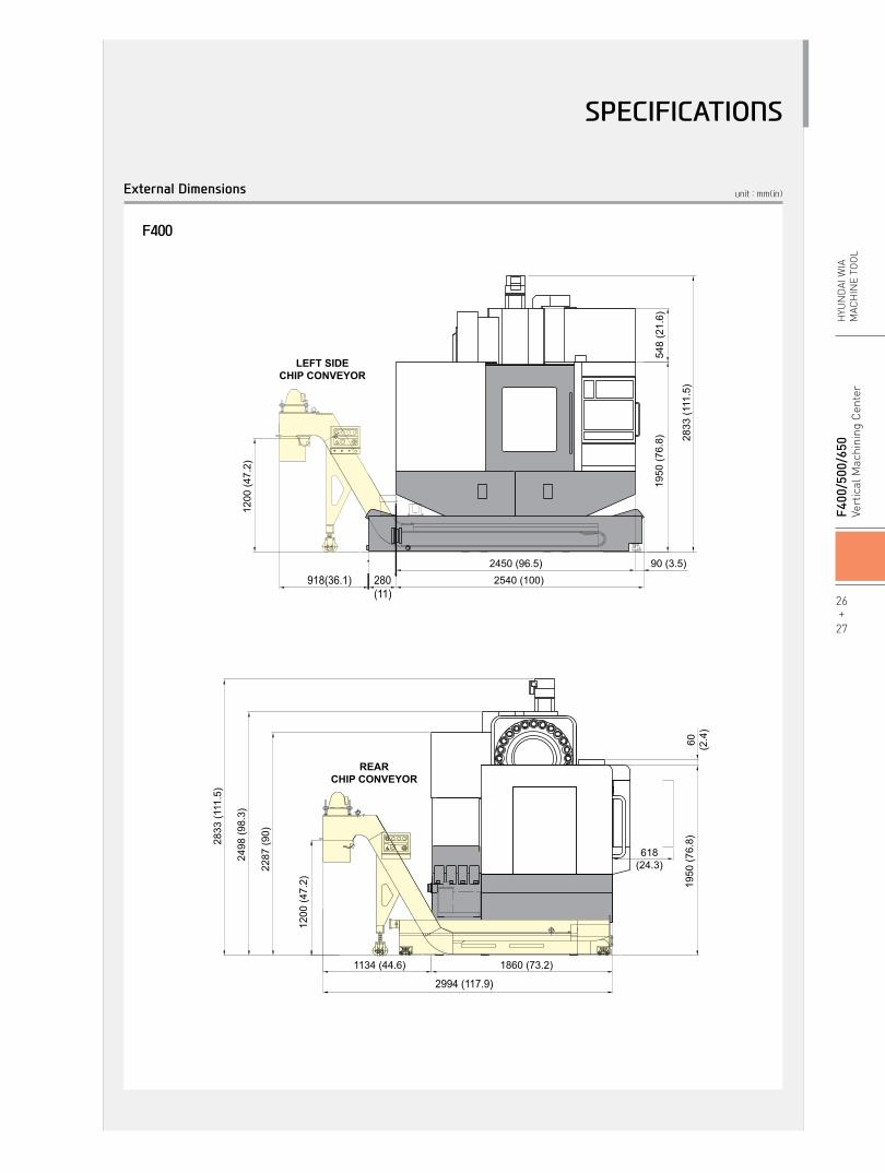
F400
548
(21.
6)
REARCHIP CONVEYOR
1950
(76.
8)
2450 (96.5) 90 (3.5)2540 (100)
1860 (73.2)
2994 (117.9)
2287
(90)
2498
(98.
3)
2833
(111
.5)
1950
(76.
8)60 (2.4
)
618(24.3)
LEFT SIDECHIP CONVEYOR
REARCHIP CONVEYOR
1900
(74.
8)20
5(8
.1)
F500
: 28
00 (1
10.2
) F5
00/5
0 : 2
876
(113
.2)
2573
(101
.3)
523
(20.
6)
2670 (105.1)
613(24.1)
ON
1950(76.8)
1134 (44.6)
1200
(47.
2)
415(16.3)
428(16.9)
120(4.7)
24To
ol :
2611
(102
.8)
30To
ol :
2760
(108
.7)
2055
(80.
9)
458(18)
1200
(47.
2)
905 (35.6) 1689 (66.5) 906 (35.6)
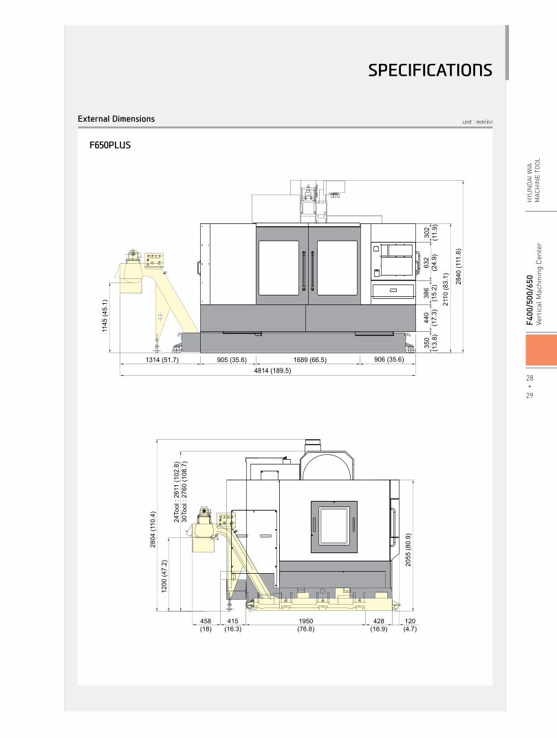
4814 (189.5)
350
(13.
8)44
0(1
7.3)
302
(11.
9)
2110
(83.
1)
386
(15.
2)63
2(2
4.9)
1314 (51.7)
1145
(45.
1)
340(13.4)
1795 (70.7)281(11.1)
708 (27.9)
1200
(47.
2)
280(11)
918(36.1)
1200
(47.
2)
LEFT SIDECHIP CONVEYOR
340
(13.
4)15
60 (6
1.4)
1197
(47.
1)19
00 (7
4.8)
378
(14.
9)
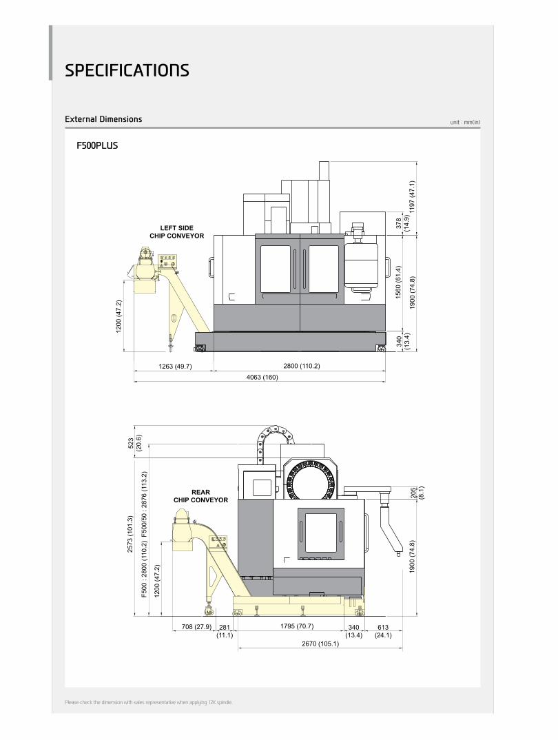
2800 (110.2)
1200
(47.
2)
1263 (49.7)4063 (160)
2804
(110
.4)
2840
(111
.8)
2833
(111
.5)
548
(21.
6)REAR
CHIP CONVEYOR
1950
(76.
8)
2450 (96.5) 90 (3.5)2540 (100)
1860 (73.2)
2994 (117.9)
2287
(90)
2498
(98.
3)
2833
(111
.5)
1950
(76.
8)60 (2.4
)
618(24.3)
LEFT SIDECHIP CONVEYOR
REARCHIP CONVEYOR
1900
(74.
8)20
5(8
.1)
F500
: 28
00 (1
10.2
) F5
00/5
0 : 2
876
(113
.2)
2573
(101
.3)
523
(20.
6)
2670 (105.1)
613(24.1)
ON
1950(76.8)
1134 (44.6)
1200
(47.
2)
415(16.3)
428(16.9)
120(4.7)
24To
ol :
2611
(102
.8)
30To
ol :
2760
(108
.7)
2055
(80.
9)
458(18)
1200
(47.
2)
905 (35.6) 1689 (66.5) 906 (35.6)
4814 (189.5)
350
(13.
8)44
0(1
7.3)
302
(11.
9)
2110
(83.
1)
386
(15.
2)63
2(2
4.9)
1314 (51.7)
1145
(45.
1)
340(13.4)
1795 (70.7)281(11.1)
708 (27.9)
1200
(47.
2)
280(11)
918(36.1)
1200
(47.
2)
LEFT SIDECHIP CONVEYOR
340
(13.
4)15
60 (6
1.4)
1197
(47.
1)19
00 (7
4.8)
378
(14.
9)
2800 (110.2)
1200
(47.
2)
1263 (49.7)4063 (160)
2804
(110
.4)
2840
(111
.8)
2833
(111
.5)
26+
27
F4
00/5
00/6
50Ve
rtic
al M
achi
ning
Cen
ter
HYU
ND
AI W
IAM
ACH
INE
TOO
L
SPECIFICATIONS
unit : mm(in)External Dimensions
F500PLUS
SPECIFICATIONS
548
(21.
6)
REARCHIP CONVEYOR
1950
(76.
8)
2450 (96.5) 90 (3.5)2540 (100)
1860 (73.2)
2994 (117.9)
2287
(90)
2498
(98.
3)
2833
(111
.5)
1950
(76.
8)60 (2.4
)
618(24.3)
LEFT SIDECHIP CONVEYOR
REARCHIP CONVEYOR
1900
(74.
8)20
5(8
.1)
F500
: 28
00 (1
10.2
) F5
00/5
0 : 2
876
(113
.2)
2573
(101
.3)
523
(20.
6)
2670 (105.1)
613(24.1)
ON
1950(76.8)
1134 (44.6)
1200
(47.
2)
415(16.3)
428(16.9)
120(4.7)
24To
ol :
2611
(102
.8)
30To
ol :
2760
(108
.7)
2055
(80.
9)
458(18)
1200
(47.
2)
905 (35.6) 1689 (66.5) 906 (35.6)
4814 (189.5)
350
(13.
8)44
0(1
7.3)
302
(11.
9)
2110
(83.
1)
386
(15.
2)63
2(2
4.9)
1314 (51.7)
1145
(45.
1)
340(13.4)
1795 (70.7)281(11.1)
708 (27.9)
1200
(47.
2)
280(11)
918(36.1)12
00 (4
7.2)
LEFT SIDECHIP CONVEYOR
340
(13.
4)15
60 (6
1.4)
1197
(47.
1)19
00 (7
4.8)
378
(14.
9)
2800 (110.2)
1200
(47.
2)
1263 (49.7)4063 (160)
2804
(110
.4)
2840
(111
.8)
2833
(111
.5)
548
(21.
6)
REARCHIP CONVEYOR
1950
(76.
8)
2450 (96.5) 90 (3.5)2540 (100)
1860 (73.2)
2994 (117.9)
2287
(90)
2498
(98.
3)
2833
(111
.5)
1950
(76.
8)60 (2.4
)
618(24.3)
LEFT SIDECHIP CONVEYOR
REARCHIP CONVEYOR
1900
(74.
8)20
5(8
.1)
F500
: 28
00 (1
10.2
) F5
00/5
0 : 2
876
(113
.2)
2573
(101
.3)
523
(20.
6)
2670 (105.1)
613(24.1)
ON
1950(76.8)
1134 (44.6)
1200
(47.
2)
415(16.3)
428(16.9)
120(4.7)
24To
ol :
2611
(102
.8)
30To
ol :
2760
(108
.7)
2055
(80.
9)
458(18)
1200
(47.
2)
905 (35.6) 1689 (66.5) 906 (35.6)
4814 (189.5)
350
(13.
8)44
0(1
7.3)
302
(11.
9)
2110
(83.
1)
386
(15.
2)63
2(2
4.9)
1314 (51.7)
1145
(45.
1)
340(13.4)
1795 (70.7)281(11.1)
708 (27.9)
1200
(47.
2)
280(11)
918(36.1)
1200
(47.
2)
LEFT SIDECHIP CONVEYOR
340
(13.
4)15
60 (6
1.4)
1197
(47.
1)19
00 (7
4.8)
378
(14.
9)
2800 (110.2)
1200
(47.
2)
1263 (49.7)4063 (160)
2804
(110
.4)
2840
(111
.8)
2833
(111
.5)
Please check the dimension with sales representative when applying 12K spindle.
SPECIFICATIONS
28+
29
F4
00/5
00/6
50Ve
rtic
al M
achi
ning
Cen
ter
HYU
ND
AI W
IAM
ACH
INE
TOO
L
unit : mm(in)External Dimensions
F650PLUS
548
(21.
6)
REARCHIP CONVEYOR
1950
(76.
8)
2450 (96.5) 90 (3.5)2540 (100)
1860 (73.2)
2994 (117.9)
2287
(90)
2498
(98.
3)
2833
(111
.5)
1950
(76.
8)60 (2.4
)
618(24.3)
LEFT SIDECHIP CONVEYOR
REARCHIP CONVEYOR
1900
(74.
8)20
5(8
.1)
F500
: 28
00 (1
10.2
) F5
00/5
0 : 2
876
(113
.2)
2573
(101
.3)
523
(20.
6)
2670 (105.1)
613(24.1)
ON
1950(76.8)
1134 (44.6)12
00 (4
7.2)
415(16.3)
428(16.9)
120(4.7)
24To
ol :
2611
(102
.8)
30To
ol :
2760
(108
.7)
2055
(80.
9)
458(18)
1200
(47.
2)
905 (35.6) 1689 (66.5) 906 (35.6)
4814 (189.5)
350
(13.
8)44
0(1
7.3)
302
(11.
9)
2110
(83.
1)
386
(15.
2)63
2(2
4.9)
1314 (51.7)
1145
(45.
1)
340(13.4)
1795 (70.7)281(11.1)
708 (27.9)
1200
(47.
2)280(11)
918(36.1)
1200
(47.
2)
LEFT SIDECHIP CONVEYOR
340
(13.
4)15
60 (6
1.4)
1197
(47.
1)19
00 (7
4.8)
378
(14.
9)
2800 (110.2)
1200
(47.
2)
1263 (49.7)4063 (160)
2804
(110
.4)
2840
(111
.8)
2833
(111
.5)
548
(21.
6)
REARCHIP CONVEYOR
1950
(76.
8)
2450 (96.5) 90 (3.5)2540 (100)
1860 (73.2)
2994 (117.9)
2287
(90)
2498
(98.
3)
2833
(111
.5)
1950
(76.
8)60 (2.4
)
618(24.3)
LEFT SIDECHIP CONVEYOR
REARCHIP CONVEYOR
1900
(74.
8)20
5(8
.1)
F500
: 28
00 (1
10.2
) F5
00/5
0 : 2
876
(113
.2)
2573
(101
.3)
523
(20.
6)
2670 (105.1)
613(24.1)
ON
1950(76.8)
1134 (44.6)
1200
(47.
2)
415(16.3)
428(16.9)
120(4.7)
24To
ol :
2611
(102
.8)
30To
ol :
2760
(108
.7)
2055
(80.
9)
458(18)
1200
(47.
2)
905 (35.6) 1689 (66.5) 906 (35.6)
4814 (189.5)
350
(13.
8)44
0(1
7.3)
302
(11.
9)
2110
(83.
1)
386
(15.
2)63
2(2
4.9)
1314 (51.7)
1145
(45.
1)
340(13.4)
1795 (70.7)281(11.1)
708 (27.9)
1200
(47.
2)
280(11)
918(36.1)
1200
(47.
2)
LEFT SIDECHIP CONVEYOR
340
(13.
4)15
60 (6
1.4)
1197
(47.
1)19
00 (7
4.8)
378
(14.
9)
2800 (110.2)
1200
(47.
2)
1263 (49.7)4063 (160)
2804
(110
.4)
2840
(111
.8)
2833
(111
.5)
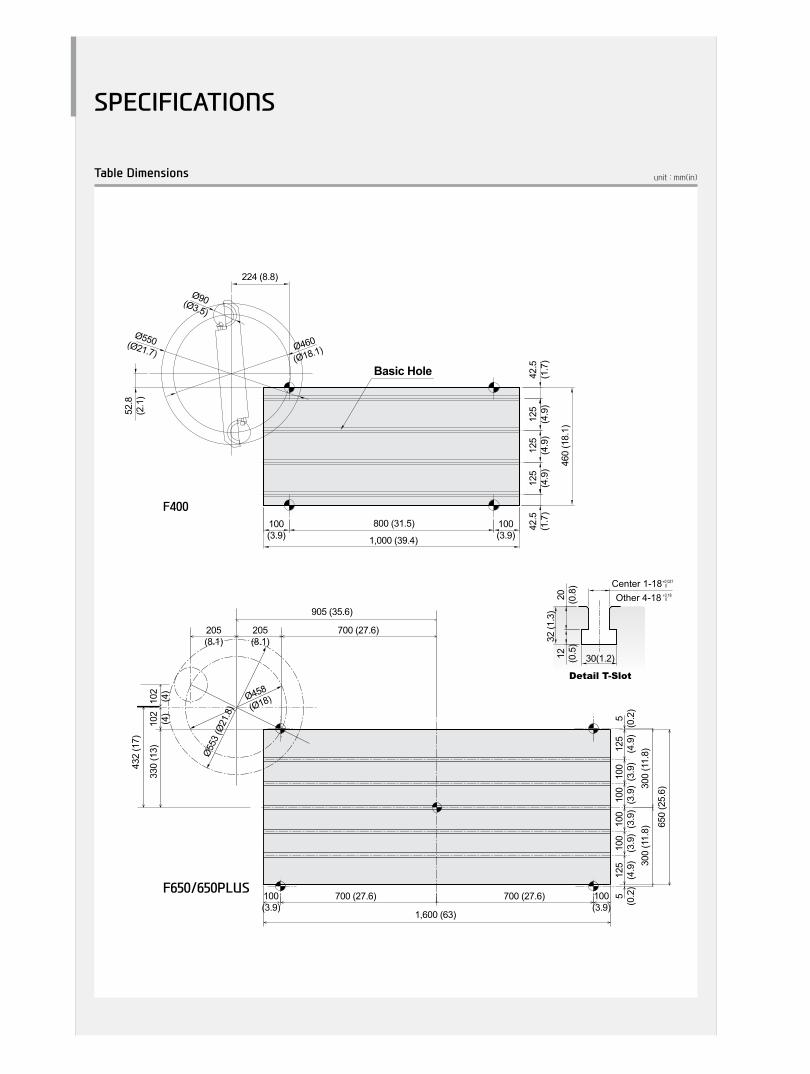
unit : mm(in)Table Dimensions
Ø90(Ø3.5)
Ø550(Ø21.7) Ø460
(Ø18.1)
100(3.9)
100(3.9)
42.5
(1.7
)42
.5(1
.7)
125
(4.9
)12
5(4
.9)
52.8
(2.1
)
224 (8.8)
460
(18.
1)
125
(4.9
)
800 (31.5)
1,000 (39.4)
Basic Hole
700 (27.6)
Ø458
(Ø18)
Ø55
3 (Ø
21.8
)
205(8.1)
205(8.1)
905 (35.6)
1,600 (63)
700 (27.6)700 (27.6) 5(0
.2)
5(0
.2)
125
(4.9
)12
5(4
.9)
650
(25.
6)
330
(13)
432
(17)
102
(4)
102
(4)
300
(11.
8)30
0 (1
1.8)
100
(3.9
)10
0(3
.9)
100
(3.9
)10
0(3
.9)
Ø553 (Ø21.8)
Ø95(Ø3.7)
Ø458 (Ø18)
1,200 (47.2)1,060 (41.7)70
(2.8)
205 (8.1)
102
(4)
70(2.8)
5(0
.2)
500
(19.
7)5
(0.2
)
50 (2)
50 (2)
100
(3.9
)10
0(3
.9)
100
(3.9
)10
0(3
.9)
100(3.9)
100(3.9)
12 (0.5
)20 (0.8
)
32 (1
.3)
30(1.2)Ø710(Ø28)
Ø600
(Ø23.6)
Ø110(Ø4.3)
1,200 (47.2)
1,100 (43.3)
5(0
.2)
500
(19.
7)5
(0.2
)
50(2)
50(2)
50 (2)
50 (2)
100
(3.9
)10
0(3
.9)
100
(3.9
)10
0(3
.9)
264.8(10.4)
141.
3(5
.6)
Detail T-Slot
12 (0.5
)20 (0.8
)
32 (1
.3)
30(1.2)
Detail T-Slot
T-SLOT DETAIL
Center 1-18Other 4-18
30 (1.2)
12 (0
.5)
20 (0
.8)
32 (1
.2)
Center 1-18Other 4-18
F400
F650/650PLUS
SPECIFICATIONS
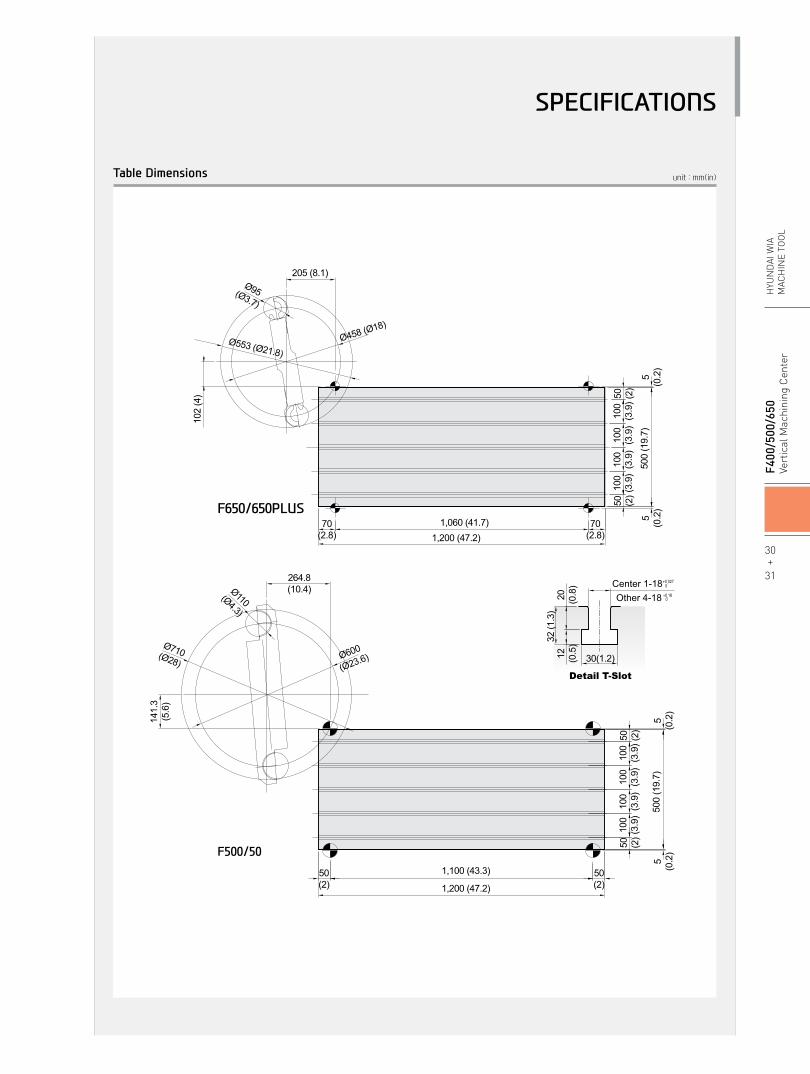
unit : mm(in)Table Dimensions
Ø90(Ø3.5)
Ø550(Ø21.7) Ø460
(Ø18.1)
100(3.9)
100(3.9)
42.5
(1.7
)42
.5(1
.7)
125
(4.9
)12
5(4
.9)
52.8
(2.1
)
224 (8.8)
460
(18.
1)
125
(4.9
)
800 (31.5)
1,000 (39.4)
Basic Hole
700 (27.6)
Ø458
(Ø18)
Ø55
3 (Ø
21.8
)
205(8.1)
205(8.1)
905 (35.6)
1,600 (63)
700 (27.6)700 (27.6) 5(0
.2)
5(0
.2)
125
(4.9
)12
5(4
.9)
650
(25.
6)
330
(13)
432
(17)
102
(4)
102
(4)
300
(11.
8)30
0 (1
1.8)
100
(3.9
)10
0(3
.9)
100
(3.9
)10
0(3
.9)
Ø553 (Ø21.8)
Ø95(Ø3.7)
Ø458 (Ø18)
1,200 (47.2)1,060 (41.7)70
(2.8)
205 (8.1)
102
(4)
70(2.8)
5(0
.2)
500
(19.
7)5
(0.2
)
50 (2)
50 (2)
100
(3.9
)10
0(3
.9)
100
(3.9
)10
0(3
.9)
100(3.9)
100(3.9)
12 (0.5
)20 (0.8
)
32 (1
.3)
30(1.2)Ø710(Ø28)
Ø600
(Ø23.6)
Ø110(Ø4.3)
1,200 (47.2)
1,100 (43.3)
5(0
.2)
500
(19.
7)5
(0.2
)
50(2)
50(2)
50 (2)
50 (2)
100
(3.9
)10
0(3
.9)
100
(3.9
)10
0(3
.9)
264.8(10.4)
141.
3(5
.6)
Detail T-Slot
12 (0.5
)20 (0.8
)
32 (1
.3)
30(1.2)
Detail T-Slot
T-SLOT DETAIL
Center 1-18Other 4-18
30 (1.2)
12 (0
.5)
20 (0
.8)
32 (1
.2)
Center 1-18Other 4-18
F650/650PLUS
F500/50
30+
31
F4
00/5
00/6
50Ve
rtic
al M
achi
ning
Cen
ter
HYU
ND
AI W
IAM
ACH
INE
TOO
L
SPECIFICATIONS
unit : mm(in)
Through coolant
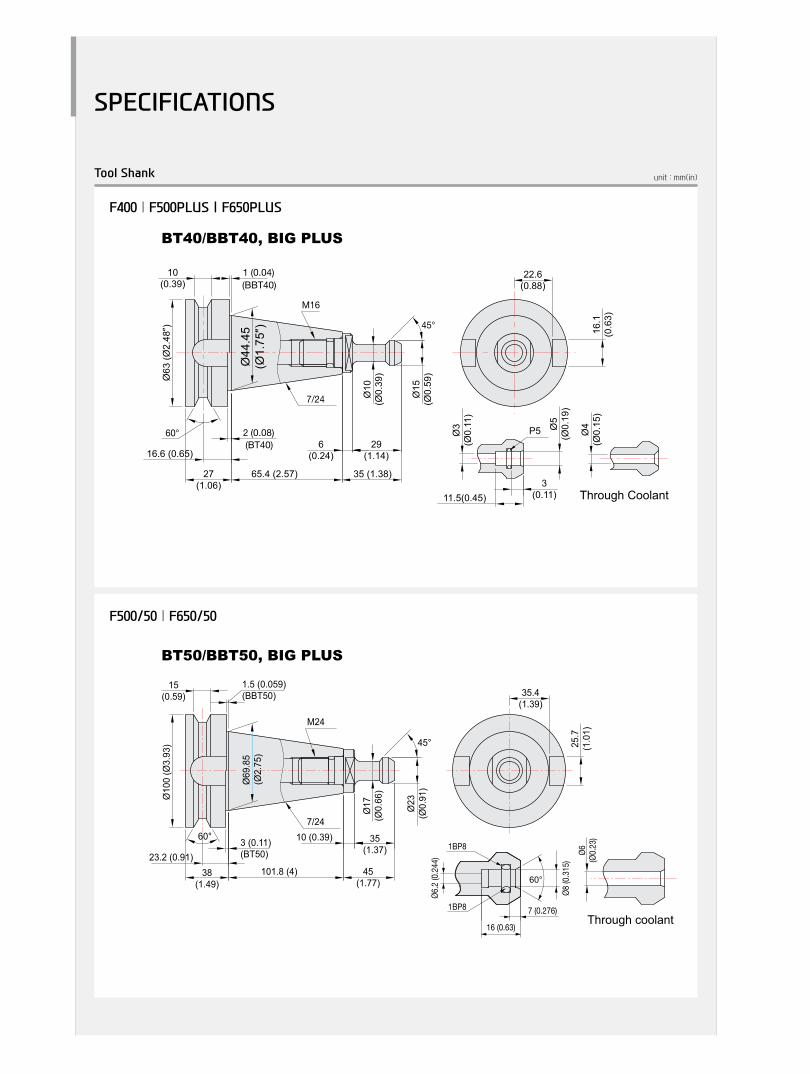
BT50/BBT50, BIG PLUS
1.5 (0.059)(BBT50) 35.4
(1.39)
25.7
(1.0
1)
Ø10
0 (Ø
3.93
)
Ø69
.85
(Ø2.
75)
Ø17
(Ø0.
66)
Ø23
(Ø0.
91)
60°
38(1.49)
23.2 (0.91)
10 (0.39)
45(1.77)
101.8 (4)
7/24
M24
35(1.37)
15(0.59)
45°
3 (0.11)(BT50) Ø6
(Ø0.
23)
60°
Ø6.2
(0.2
44)
Ø8 (0
.315
)
1BP8
1BP8
16 (0.63)
7 (0.276)
Ø63
(Ø2.
48″)
65.4 (2.57)
6(0.24)
27(1.06)
2 (0.08)
Ø44
.45
(Ø1.
75″)
35 (1.38)
29(1.14)
Ø15
(Ø0.
59)
60°
45°
16.6 (0.65)
7/24
M16
Ø10
(Ø0.
39)
10(0.39)
1 (0.04)(BBT40)
(BT40)
BT40/BBT40, BIG PLUS
22.6(0.88)
16.1
(0.6
3)
Ø4
(Ø0.
15)
Ø3
(Ø0.
11)
Ø5
(Ø0.
19)
11.5(0.45)3
(0.11)
P5
Through Coolant
F500/50 | F650/50
F400 | F500PLUS | F650PLUS
Tool Shank
SPECIFICATIONS
unit : mm(in)
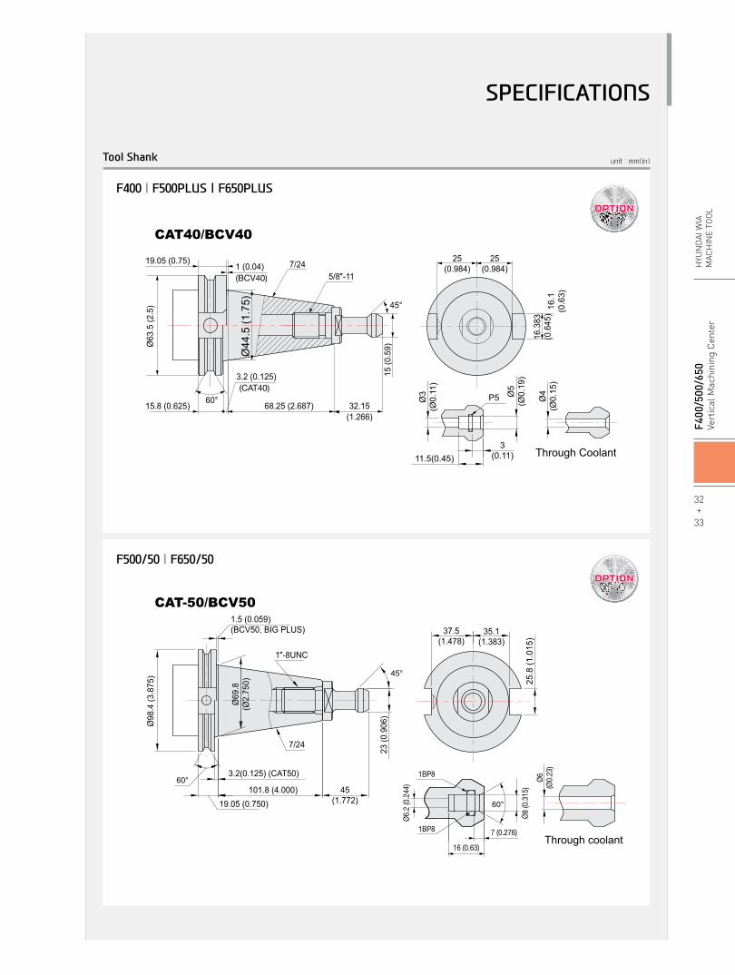
(BCV40)
(CAT40)60°
45°
CAT40/BCV40
Ø63
.5 (2
.5)
15 (0
.59)
25(0.984)
25(0.984)
16.3
83(0
.645
)
68.25 (2.687)15.8 (0.625)
19.05 (0.75)
3.2 (0.125)
1 (0.04) 7/24
32.15(1.266)
5/8″-11
Ø44
.5 (1
.75) 16
.1(0
.63)
Ø4
(Ø0.
15)
Ø3
(Ø0.
11)
Ø5
(Ø0.
19)
11.5(0.45)3
(0.11)
P5
Through Coolant
Through coolant
CAT-50/BCV50
Ø6(Ø
0.23
)
60°
Ø6.2
(0.2
44)
Ø8 (0
.315
)
1BP8
1BP8
16 (0.63)
7 (0.276)
101.8 (4.000)
Ø69
.8(Ø
2.75
0)
Ø98
.4 (3
.875
)
19.05 (0.750)45
(1.772)
1.5 (0.059)(BCV50, BIG PLUS) 37.5
(1.478)35.1
(1.383)
25.8
(1.0
15)
1″-8UNC
7/24
23 (0
.906
)
60°3.2(0.125) (CAT50)
45°
F500/50 | F650/50
F400 | F500PLUS | F650PLUS
Tool Shank
32+
33
F4
00/5
00/6
50Ve
rtic
al M
achi
ning
Cen
ter
HYU
ND
AI W
IAM
ACH
INE
TOO
L
SPECIFICATIONS
Specifications are subject to change without notice for improvement.
Table Size
Maximum Load Capacity
Table Change Time
Change Method
Table Driving Method
Spindle Taper
Spindle RPM
Spindle Power Output (Max./Cont.)
Spindle Torque (Max./Cont.)
Spindle Driving Method
Travel (X/Y/Z)
Distance from Table Surface to SP
Distance from Column to SP. center
Rapid Traverse Rate (X/Y/Z)
Slide Type
Number of Tools
Tool Shank
Max. Tool Dia. (W.T / W.O)
Max. Tool Length
Max. Tool Weight
Tool Selection Method
Tool Change Time T-T
C-C
Coolant Tank
Lubricating Tank
Hydraulic Tank
Air Consumption (0.5MPa)
Electric Power Supply
Thickness of Power Cable
Voltage
Floor Space (L×W)
Height
Weight
Controller
mm(in)
kg(lb)
sec
-
-
-
r/min
kW(HP)
N.m(lbf.ft)
-
mm(in)
mm(in)
mm(in)
m/min(ipm)
-
EA
-
mm(in)
mm(in)
kg(lb)
-
sec
sec
ℓ(gal)
ℓ(gal)
ℓ(gal)
ℓ/min(gal)
KVA
Sq
V/Hz
mm(in)
mm(in)
kg(lb)
-
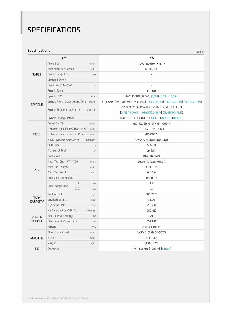
ITEM F400
1,000×460 (39.4″×18.1″)
600 (1,323)
-
-
-
NT #40
8,000 [8,000] [12,000] [8,000] [8,000] [12,000]
15/11(20/15) [15/11(20/15)] [11/7.5(15/10)] [13.5/9(18.1/12)] [15.8/10.5(21/14)] [15.8/10.5(21/14)]
95/70(70.0/51.6) [95/70(70.0/51.6)] [70/45(51.6/33.2)]
[95/63(70.0/46.5)] [95/63(70.0/46.5)] [95/63(70.0/46.5)]
Direct [Belt] [Direct] [Belt] [DirecT] [DirecT]
800/460/520 (31.5″/18.1″/20.5″)
130~650 (5.1″~25.6″)
475 (18.7″)
32/32/32 (1,260/1,260/1,260)
lM GuiDe
24 [30]
Bt40 [BBt40]
Ø90/Ø150 (Ø3.5″/Ø5.9″)
300 (11.8″)
8 (17.6)
ranDoM
1.3
3.6
300 (79.3)
2 (0.5)
20 (5.3)
250 (66)
20
Over 25
220/60 (200/50)
2,450×2,100 (96.5″×82.7″)
2,833 (111.5″)
5,100 (11,244)
HW F i Series [F 32i-a] [S 828D]
Specifications [ ] : Option
TAbLE
SPINDLE
FEED
ATC
MACHINE
NC
TANkCAPACITY
PoWErSUPPLY
SPECIFICATIONS

Specifications are subject to change without notice for improvement.
Table Size
Maximum Load Capacity
Table Change Time
Change Method
Table Driving Method
Spindle Taper
Spindle RPM
Spindle Power Output
(Max./Cont.)
Spindle Torque
(Max./Cont.)
Spindle Driving Method
Travel (X/Y/Z)
Distance from Table Surface to SP
Distance from Column to SP. center
Rapid Traverse Rate (X/Y/Z)
Slide Type
Number of Tools
Tool Shank
Max. Tool Dia. (W.T / W.O)
Max. Tool Length
Max. Tool Weight
Tool Selection Method
Tool Change Time T-T
C-C
Coolant Tank
Lubricating Tank
Hydraulic Tank
Air Consumption (0.5MPa)
Electric Power Supply
Thickness of Power Cable
Voltage
Floor Space (L×W)
Height
Weight
Controller
mm(in)
kg(lb)
sec
-
-
-
r/min
kW(HP)
N.m(lbf.ft)
-
mm(in)
mm(in)
mm(in)
m/min(ipm)
-
EA
-
mm(in)
mm(in)
kg(lb)
-
sec
sec
ℓ(gal)
ℓ(gal)
ℓ(gal)
ℓ/min(gal)
KVA
Sq
V/Hz
mm(in)
mm(in)
kg(lb)
-
ITEM F500PLUS F500/50
1,200×500 (47.2″×19.7″)
800 (1,764)
-
-
-
BiG PluS #40 nt #50
8,000 [10,000] [12,000] 6,000 [6,000]
15/11 (20/15) [18.5/15 (24.8/20)]
15/11 (20/15)
[18.5/11 (24.8/14.7)] [27.8/18.5 (37.3/24.8)]
286/143 (210.9/105.4) [117.6/95.3 (86.7/70.3)] 358/179 (264.0/132.0)
[117.7/70 (86.8/51.6)] [294/196 (216.8/97.4)]
Belt [Belt] [Direct] Belt [Belt]
1,060/510/635 (41.7″/20.1″/25″) 1,100/510/635 (43.3″/20.1″/25″)
150~785 (5.9″~30.9″)
615 (24.2″)
36/36/30 (1,417/1,417/1,260)
roller GuiDe
30 24
BBt40 Bt50 [BBt50]
Ø80/Ø125 (Ø3.1″/Ø4.9″) Ø110/Ø200 (Ø4.3″/Ø7.9″)
300 (11.8″) 350 (13.8″)
8 (17.6) 15 (33.1)
ranDoM
1.3 3.8
3.7 5.9
350 (92.5)
2 (0.5)
15 (4)
110 (29.1)
23
Over 25
220/60 (200/50)
2,910×2,690 (114.6″×105.9″) 2,910×2,860 (114.6″×112.6″)
2,815 (110.8″) 3,021 (118.9″)
7,500 (16,976) 7,700 (16,976)
HW F i Series HW F i Series [F 32i-B] [S 828D]
Specifications [ ] : Option
TAbLE
SPINDLE
FEED
ATC
MACHINE
NC
TANkCAPACITY
PoWErSUPPLY
34+
35
F4
00/5
00/6
50Ve
rtic
al M
achi
ning
Cen
ter
HYU
ND
AI W
IAM
ACH
INE
TOO
L
SPECIFICATIONS

Specifications are subject to change without notice for improvement.
Table Size
Maximum Load Capacity
Table Change Time
Change Method
Table Driving Method
Spindle Taper
Spindle RPM
Spindle Power Output
(Max./Cont.)
Spindle Torque
(Max./Cont.)
Spindle Driving Method
Travel (X/Y/Z)
Distance from Table Surface to SP
Distance from Column to SP. center
Rapid Traverse Rate (X/Y/Z)
Slide Type
Number of Tools
Tool Shank
Max. Tool Dia. (W.T / W.O)
Max. Tool Length
Max. Tool Weight
Tool Selection Method
Tool Change Time T-T
C-C
Coolant Tank
Lubricating Tank
Hydraulic Tank
Air Consumption (0.5MPa)
Electric Power Supply
Thickness of Power Cable
Voltage
Floor Space (L×W)
Height
Weight
Controller
TAbLE
FEED
SPINDLE
ATC
MACHINE
NC
mm(in)
kg(lb)
sec
-
-
-
r/min
kW(HP)
N.m(lbf.ft)
-
mm(in)
mm(in)
mm(in)
m/min(ipm)
-
EA
-
mm(in)
mm(in)
kg(lb)
-
sec
sec
ℓ(gal)
ℓ(gal)
ℓ(gal)
ℓ/min(gal)
KVA
Sq
V/Hz
mm(in)
mm(in)
kg(lb)
-
ITEM F650PLUS F650/50
1,600×650 (63″×25.6″)
1,300 (2,866)
-
-
-
BiG PluS #40 nt #50
8,000 [10,000] 6,000 [6,000]
15/11 (20/15) 15/11 (20/150)
[18.5/15 (25/20)] [27.8/18.5 (37.3/24.8)]
286/143 (210.9/105.4) 358/179 (264.0/132)
[117.6/95.3 (86.7/70.3)] [294/196 (216.8/97.4)]
Belt
1,400/660/635 (55.1″/26″/25″)
150 ~ 785 (5.9″~30.9″)
735 (28.9″)
36/36/30 (1,417/1,417/1,260)
roller GuiDe
30 24
BBt40 Bt50 [BBt50]
Ø80/Ø125 (Ø3.1″/Ø4.9″) Ø110/Ø200 (Ø4.3″/Ø7.9″)
300 (11.8″) 350 (13.8″)
8 (17.6) 15 (33.1)
ranDoM
1.3 3.8
3.8 6
350 (92.5)
2 (0.5)
- 15 (4)
125 (33.0) 110 (29.1)
24
Over 25
220/60 (200/50)
3,500×2,560 (137.8″×100.8″)
2,810 (110.6″) 2,871 (113″)
9,500 (20,944)
HW F i Series HW F i Series [F 32i-a] [S 828D]
Specifications [ ] : Option
TANkCAPACITY
PoWErSUPPLY
SPECIFICATIONS
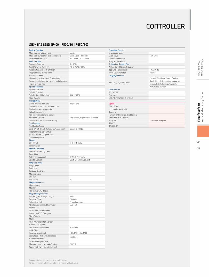
SIEMENS 828D (F400 | F500/50 | F650/50)Control FunctionMax. configuration of axisMax. configuration of axis and spindleLeast Command/inputFeed FunctionFeedrate OverrideRapid Traverse OverrideAcceleration with jerk limitationProgrammable accelerationFollow-up modeMeasuring system 1 and 2, selectableSeparate path feed for corners and chamfersTravel to fixed stopSpindle FunctionsSpindle OverrideSpindle OrientationSpindle Speed LimitationRigid TappingInterpolationsLinear interpolation axisCircle via center point and end point Circle via interpolation pointHelical interpolationnon-uniform rational B splinesAdvanced SurfaceCompressor for 3-axis machiningTool FunctionTool Radius Comp.Zero Offset (G54, G55, G56, G57 ,G58, G59)Programmable Zero Offset3D Tool Radius CompensationTool managementDisplayCRT / MDIScreen saverManual operationManual Handle/Jog FeedRepositionReference ApproachSpindle ControlAuto operationSingle BlockFeed HoldOptional Block SkipMachine LockDry RunSimulationDiagnosis FunctionAlarm displayMonitorPLC status/LAD displayProgramming FunctionPart Program Storage LengthProgram NameSubroutine CallAbsolute/incremental CommandScaling, ROTInch / Metric ConversionInteractive CYCLE programBlock SearchMacroRead / Write System VariableBackGround EditingMiscellaneous FunctionsLable SkipProgram Stop / End Lookahead , Jerk Limitation Feed & Forward ControlSIEMENS Program exe.Maximum number of tools/cuttingsNumber of levels for skip blocks 1
5 axis6 axis (axis + spindle)0.0001mm / 0.00001inch
0 - 120%F0, 5, 25/50, 100%
50% - 120% Max 4 axis
High Speed, High Rigidity Function
Standard 100 EA
TFT 10.4˝ Color
Ref 1, 2 ApproachStart, Stop, Rev, Jog, Ort.
2D
5MB23 digitsProtection LevelG90 - G91
M - Code M00, M01, M02, M30
150 Block
256/512
Protection FunctionEmergency StopOver TravelContour MonitoringProgram ProtectionAutomation Support Fun.Actual Speed Display(Monitor)Tool Life ManagementWork Count FunctionLanguage Function
Two Language switchable
Data TransferRS 232C I/FEthernetUSB Memory Stick & CF Card
optionDRF offsetLoad and save of MDITeach-inNumber of levels for skip blocks 8 Simulation in 3D displayShop Mill TRACYLTRANSMIT
Figures in inch are converted from metric values.Design and specifications are subject to change without notice.
Soft Limit
Time, PartsInternal
Chinese Traditional, Czech, Danish, Dutch, Finnish, Hungarian, Japanese, Korean, Polish, Russian, Swedish, Portuguese, Turkish
Interactive program
CONTROLLER
36+
37
F4
00/5
00/6
50Ve
rtic
al M
achi
ning
Cen
ter
HYU
ND
AI W
IAM
ACH
INE
TOO
L
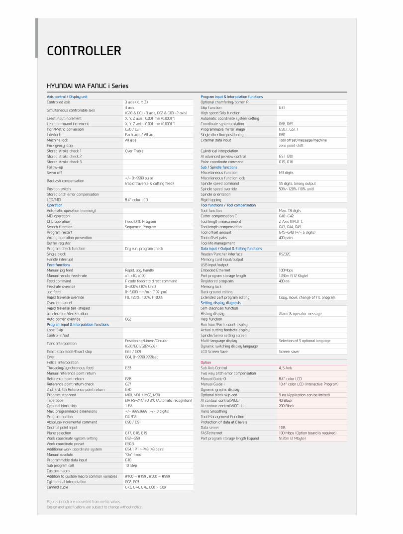
HYUNDAI WIA FANUC i SeriesAxis control / Display unitControlled axis
Simultaneous controllable axis
Least input incrementLeast command incrementInch/Metric conversionInterlockMachine lockEmergency stopStored stroke check 1Stored stroke check 2Stored stroke check 3Follow-upServo off
Backlash compensation
Position switchStored pitch error compensationLCD/MDIoperationAutomatic operation (memory)MDI operationDNC operationSearch functionProgram restartWrong operation preventionBuffer registerProgram check functionSingle blockHandle interruptFeed functionsManual jog feedManual handle feed-rateFeed commandFeedrate overrideJog feedRapid traverse overrideOverride cancelRapid traverse bell-shaped acceleration/decelerationAuto corner overrideProgram input & Interpolation functionsLabel SkipControl in/out
Nano Interpolation
Exact stop mode/Exact stopDwellHelical interpolationThreading/synchronous feedManual reference point returnReference point returnReference point return check2nd, 3rd, 4th Reference point returnProgram stop/endTape codeOptional block skipMax. programmable dimensionsProgram numberAbsolute/incremental commandDecimal point inputPlane selectionWork coordinate system settingWork coordinate presetAdditional work coordinate systemManual absoluteProgrammable data inputSub program callCustom macroAddition to custom macro common variablesCylinderical interpolationCanned cycle
3 axis (X, Y, Z)3 axis(G00 & G01 : 3 axis, G02 & G03 : 2 axis)X, Y, Z axis : 0.001 mm (0.0001″)X, Y, Z axis : 0.001 mm (0.0001″)G20 / G21Each axis / All axisAll axis
Over Trable
+/- 0~9999 pulse(rapid traverse & cutting feed)
8.4″ color LCD
Need DNC Program Sequence, Program
Dry run, program check
Rapid, Jog, handlex1, x10, x100F code feedrate direct command0~200% (10% Unit)0~5,000 mm/min (197 ipm)F0, F25%, F50%, F100%
G62
Positioning/Linear/Circular(G00/G01/G02/G03)G61 / G09G04, 0~9999.9999sec
G33
G28G27G30M00, M01 / M02, M30EIA RS-244/ISO 840 (Automatic recognition)1 EA+/- 9999.9999 (+/- 8 digits)O4 /N8G90 / G91
G17, G18, G19G52~G59G50.3G54.1 P1 ~P48 (48 pairs)"On" fixedG1010 Step
#100 ~ #199 , #500 ~ #999G02, G03G73, G74, G76, G80 ~ G89
Program input & Interpolation functionsOptional chamfering/corner RSkip functionHigh speed Skip functionAutomatic coordinate system settingCoordinate system rotationProgrammable mirror imageSingle direction positioningExternal data input
Cylindrical interpolationAI advanced preview controlPolar coordinate commandSub / Spindle functionsMiscellaneous functionMiscellaneous function lockSpindle speed commandSpindle speed overrideSpindle orientationRigid tappingTool functions / Tool compensationTool functionCutter compensation CTool length measurementTool length compensationTool offset amountTool offset pairsTool life managementData input / output & Editing functionsReader/Puncher interfaceMemory card input/outputUSB input/outputEmbeded EthernetPart program storage lengthRegistered programsMemory lockBack ground editingExtended part program editingSetting, display, diagnosisSelf-diagnosis functionHistory displayHelp functionRun hour/Parts count displayActual cutting feedrate displaySpindle/Servo setting screenMulti-language displayDynamic switching display languageLCD Screen Save
optionSub Axis ControlTwo way pitch error compensationManual Guide 0iManual Guide iDynamic graphic displayOptional block skip addAI contour control(AICC) AI contour control(AICC) ⅡNano SmoothingTool Management FunctionProtection of data at 8 levelsData serverFASTethernetPart program storage length Expand
Figures in inch are converted from metric values.Design and specifications are subject to change without notice.
G31
G68, G69G50.1, G51.1G60Tool offset/message/machine zero point shift
G5.1 (20)G15, G16
M3 digits
S5 digits, binary output50%~120% (10% unit)
Max. T8 digitsG40~G42Z Axis INPUT CG43, G44, G49G45~G48 (+/- 6 digits)400 pairs
RS232C
100Mbps1280m (512 Kbyte)400 ea
Copy, move, change of NC program
Alarm & operator message
Selection of 5 optional language
Screen saver
4, 5 Axis
8.4″ color LCD10.4″ color LCD (Interactive Program)
9 ea (Application can be limited)40 Block200 Block
1GB100 Mbps (Option board is required)5120m (2 Mbyte)
CONTROLLER
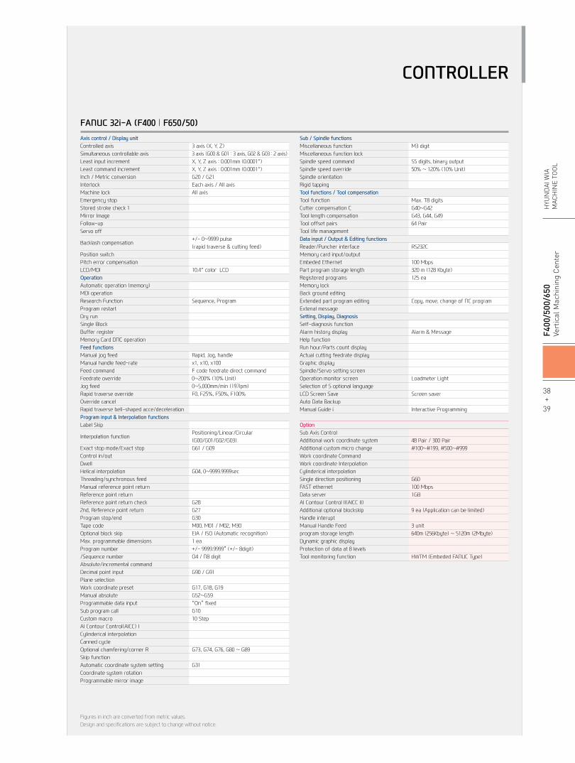
FANUC 32i-A (F400 | F650/50)Axis control / Display unitControlled axisSimultaneous controllable axisLeast input incrementLeast command incrementInch / Metric conversionInterlockMachine lockEmergency stopStored stroke check 1Mirror ImageFollow-upServo off
Backlash compensation
Position switchPitch error compensationLCD/MDIoperationAutomatic operation (memory)MDI operationResearch FunctionProgram restartDry runSingle BlockBuffer registerMemory Card DNC operationFeed functionsManual jog feedManual handle feed-rateFeed commandFeedrate overrideJog feedRapid traverse overrideOverride cancelRapid traverse bell-shaped acce/decelerationProgram input & Interpolation functionsLabel Skip
Interpolation function
Exact stop mode/Exact stopControl in/outDwellHelical interpolationThreading/synchronous feedManual reference point returnReference point returnReference point return check2nd, Reference point returnProgram stop/endTape codeOptional block skipMax. programmable dimensionsProgram number/Sequence numberAbsolute/incremental commandDecimal point inputPlane selectionWork coordinate presetManual absoluteProgrammable data inputSub program callCustom macroAI Contour Control(AICC) ICylinderical interpolationCanned cycleOptional chamfering/corner RSkip functionAutomatic coordinate system settingCoordinate system rotationProgrammable mirror image
3 axis (X, Y, Z)3 axis (G00 & G01 : 3 axis, G02 & G03 : 2 axis)X, Y, Z axis : 0.001mm (0.0001″)X, Y, Z axis : 0.001mm (0.0001″)G20 / G21Each axis / All axisAll axis
+/- 0~9999 pulse(rapid traverse & cutting feed)
10.4″ color LCD
Sequence, Program
Rapid, Jog, handlex1, x10, x100F code feedrate direct command0~200% (10% Unit)0~5,000mm/min (197ipm)F0, F25%, F50%, F100%
Positioning/Linear/Circular(G00/G01/G02/G03)G61 / G09
G04, 0~9999.9999sec
G28G27G30M00, M01 / M02, M30EIA / ISO (Automatic recognition)1 ea+/- 9999.9999” (+/- 8digit)O4 / N8 digit
G90 / G91
G17, G18, G19G52~G59“On” fixedG1010 Step
G73, G74, G76, G80 ~ G89
G31
Sub / Spindle functionsMiscellaneous functionMiscellaneous function lockSpindle speed commandSpindle speed overrideSpindle orientationRigid tappingTool functions / Tool compensationTool functionCutter compensation CTool length compensationTool offset pairsTool life managementData input / output & Editing functionsReader/Puncher interfaceMemory card input/outputEmbeded EthernetPart program storage lengthRegistered programsMemory lockBack ground editingExtended part program editingExtenal messageSetting, Display, DiagnosisSelf-diagnosis functionAlarm history displayHelp functionRun hour/Parts count displayActual cutting feedrate displayGraphic displaySpindle/Servo setting screenOperation monitor screenSelection of 5 optional languageLCD Screen SaveAuto Data BackupManual Guide i
optionSub Axis ControlAdditional work coordinate systemAdditional custom micro changeWork coordinate CommandWork coordinate InterpolationCylinderical interpolationSingle direction positioningFAST ethernetData serverAI Contour Control II(AICC II)Additional optional blockskipHandle interuptManual Handle Feedprogram storage lengthDynamic graphic displayProtection of data at 8 levelsTool monitoring function
Figures in inch are converted from metric values.Design and specifications are subject to change without notice.
M3 digit
S5 digits, binary output50% ~ 120% (10% Unit)
Max. T8 digitsG40~G42G43, G44, G4964 Pair
RS232C
100 Mbps320 m (128 Kbyte)125 ea
Copy, move, change of NC program
Alarm & Message
Loadmeter Light
Screen saver
Interactive Programming
48 Pair / 300 Pair#100~#199, #500~#999
G60100 Mbps1GB
9 ea (Application can be limited)
3 unit640m (256Kbyte) ~ 5120m (2Mbyte)
HWTM (Embeded FANUC Type)
CONTROLLER
38+
39
F4
00/5
00/6
50Ve
rtic
al M
achi
ning
Cen
ter
HYU
ND
AI W
IAM
ACH
INE
TOO
L
Figures in inch are converted from metric values.Design and specifications are subject to change without notice.
CONTROLLER
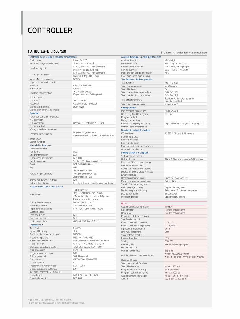
FANUC 32i-B (F500/50) [ ] : Option, ☆ Needed technical consultation
Controlled axis / Display / Accuracy compensationControl axes 3 axes (X, Y, Z)Simultaneously controlled axes 2 axes [Max. 4 axes]
Least setting UnitX, Y, Z, axes : 0.001 mm (0.0001″)B axes : 1 deg [0.001] deg
Least input incrementX, Y, Z, axes : 0.001 mm (0.0001″)B axes : 1 deg [0.001] deg
Inch / Metric conversion G20/G21 High response vector controlInterlock All axes / Each axisMachine lock All axes
Backlash compensation ± 0 ~ 9999 pulses(Rapid traverse / Cutting feed)
Position switchLCD / MDI 10.4″ color LCDFeedback Absolute motor feedbackStored stroke check 1 Over travelStored pitch error compensationOperationAutomatic operation (Memory)MDI operationDNC operation Needed DNC software / CF cardProgram restartWrong operation prevention
Program check functionDry run, Program checkZ axes Machine lock, Stroek check before move
Single blockSearch functionInterpolation functionsNano interpolationPositioning G00Linear interpolation G01Cylinderical interpolation G02, G03Exact stop mode Single : G09, Continuous : G61Dwell G04 0~9999.9999 secSkip G31
Reference position return 1st reference : G28 Ref. position check : G272nd reference : G30
Thread synchronous cutting G33Helical interpolation Circular + Linear interpolation 2 axes(max.)Feed function / Acc. & Dec. control
Manual feed
Rapid traverse Jog : 0~2,000 mm/min (79 ipm) Manual handle : x1, x10, x100 pulsesReference position return
Cutting Feed command Direct input F codeFeedrate override 0 ~ 200% (10% Unit)Rapid traverse override F1%, F5%, F25% / 50%, F100%Override cancelFeed per minute G98Feed per revolution G99Look-ahead block 40 Block, 200 Block (Mold)Program inputTape Code EIA/ISOOptional block skip 1EAAbsolute / Incremental program G90/G91Program stop / end M00, M01/M02, M30Maximum command unit ±999,999.999 mm (±99,999.9999 inch)Plane selection X-Y : G17, X-Z : G18, Y-Z : G19Workpiece coordinate system G52, G53, 6 pairs (G54 ~ G59)Manual absolute Fixed ON Programmable data input G10Sub program call 10 folds nestedCustom macro #100~#199, #500~#999G code system AProgrammable mirror image G51.1, G50.1G code preventing buffering G4.1Including Chamfering / Corner RCanned cycle G73, G74, G76, G80 ~ G89Coordinate rotation G68, G69
Auxiliary function / Spindle speed functionAuxiliary function M & 4 digitLevel-up M code Multi / Bypass M codeSpindle speed function S & 5 digit , Binary outputSpindle override 50% ~ 150% (10% Unit)Multi position spindle orientation M19FSSB high speed rigid tappingTool function / Tool compensationTool function Max. T 8 digitTool life management ☆ 256 pairsTool offset pairs 64 pairsTool nose radius compensation G40, G41, G42Tool nose length compensation G43, G44, G49
Tool offset memory C Tool length, diameter, abrasion(length, diameter)
Tool length measurement Z axes Input CEditing functionPart program storage size 640m (256KB)No. of registerable programs 500 EAProgram protectBackground editingExtended part program editing Copy, move and change of NC programMemory card program edit Data input / output & InterfaceI/O interface RS 232C, CF card, USB memoryScreen hard copyExternal messageExternal key inputExternal workpiece number searchAutomatic data backupSetting, display and diagnosisSelf-diagnosis functionHistory display Alarm & Operator message & OperationRun hour / Parts count displayMaintenance informationActual cutting feedrate displayDisplay of spindle speed / T codeGraphic displayOperating monitor screen Spindle / Servo load etc...Power consumption monitoring Spindle & ServoSpindle / Servo setting screenMulti language display Support 20 languagesDisplay language switching Selection of 5 optional LanguagesLCD Screen Saver Screen saverProcessing select Speed/ridigity setting
OptionAdditional optional block skip ☆ 9 EAFast ethernet Needed option boardData server Needed option boardProtection of data at 8 levelsSub Spindle controlPolar coordinate command G15, G16Polar coordinate interpolation G12.1, G13.1Cylinderical interpolation G07.1One-way positioning G60 Stored stroke check 2, 3Inverse-time feed G93Scaling G50, G51Manual guide i Interactive auto programHandle interruptManual handle feed 2/3 units
Additional custom macro variables#100~#199, #500~#999#100~#199, #500~#999, #98000~#98499
Rigid tap ReturnTool management functionTool offset number ☆ Max. 400 pairProgram storage capacity ☆ 512KB~2MBProgram registration number ☆ Max. 1000 eaAdditional work coordinate 48 pair (G54.1 P1 ~ P48)AICC Ⅱ 200 block, ☆ 400 block

40+
41
F4
00/5
00/6
50Ve
rtic
al M
achi
ning
Cen
ter
HYU
ND
AI W
IAM
ACH
INE
TOO
L
GLOBAL NETWORK
Changwon Technical Center / R&D Center / Factory153, Jeongdong-ro, Seongsan-gu, Changwon-si, Gyeongsangnam-do, Korea (Zip Code : 51533)TEL : +82 55 280 9114 FAX : +82 55 282 9680
Uiwang Technical Center / R&D Center37, Cheoldobangmulgwan-ro, Uiwang-si, Gyeonggi-do, Korea (Zip Code : 16082)TEL : +82 31 596 8209 Fax : +82 55 210 9804
HEADqUARTER
OVERSEAS OFFICESHYUNDAI WIAMachine Tools America 265, Spring Lake Drive, Itasca, IL, 60143
TEL : +1 201 489 2887 FAX : +1 201 489 2723
Jiangsu HYUNDAI WIANo.6 Fenghuang Road, Fenghuang Town, Zhangjjagang City, Jiangsu province, China
TEL : +86 512 5672 6808FAX : +86 512 5671 6960
Chengdu OfficeNO.508 Room, B Block, AFC Plaza, NO.88 Jiaozi Road, High-tech Zone, Chengdu, China 610041
TEL : +86 28 8665 5550FAX : +86 28 8666 2985
HYUNDAI WIAMachine Tools Europe Kaiserleipromenade 5, D-63067 Offenbach, Germany
TEL : +49 69271 472 701FAX : +49 69271 472 719
Hyundai WIA Machine Tools ChinaShanghai Office1-3F, Bldg6, No.1535 Hongmei Road, Xuhui District, Shanghai, China, 200233
TEL : +86 21 6427 9885FAX : +86 21 3431 0376
Wuhan Office Room 302, B tower, Donghe Center, Dongfeng three road, Zhuankou, Wuhan, Hubei, China 430056
TEL : +86 27 5956 3256~7FAX : +86 27 5952 3258
Raunheim Service CenterRaunheim R&D CenterKelsterbacher Strasse 51, 65479 Raunheim, Germany
TEL : +49 6142 9256 0 FAX : +49 6142 834 100
Beijing Office13 Floor Building B Zhonghangji square, No.15 Ronghua South Road, Yizhuang Economic and Technological Development Zone District, Beijing, China 100176
TEL : +86 10 8453 9850~2FAX : +86 10 8453 9853
qingdao OfficeRoom 1207, Caifu Building, 182-6 Haier Middle Road, Qingdao, China 266061
TEL : +86 532 8667 9333~5FAX : +86 532 8667 9338
Inida Office#4/169, Rajiv Gandhi Salai, (OMR), Kandanchavadi, Chennai-600 096, Tamilnadu, IndiaTEL: +91-44-3290-1719
Guangzhou OfficeRoom 311, Unit 1-3, Poly Tal Tu Wun, Hanxi Avenue, Panyu District, Guangzhou, China 511400
TEL : +86 20 8550 6595~6 FAX : +86 20 8550 6597
Shenyang OfficeRoom 1304, NO.53 Beizhan Road, Shenhe District, Shenyang, China 110013
TEL : +86 24 3228 6640FAX : +86 24 3228 6642

2015-12 003.003 ENG
Head office & Factory153, Jeongdong-ro, Seongsan-gu, Changwon-si, Gyeongsangnam-do
Tel +82 55 280 9206, 9299 Fax +82 55 210 9804
machine.hyundai-wia.com
overseas Sales Team16F, 37, Cheoldobangmulgwan-ro, Uiwang-si, Gyeonggi-do
Tel +82 31 593 8173
Carrier NCrTF650 PLUS Movie Carrier Automationknuckle NCrT


