Page 1
8/8/2019 f5k Qsg English
http://slidepdf.com/reader/full/f5k-qsg-english 1/12
General InformationInstallation
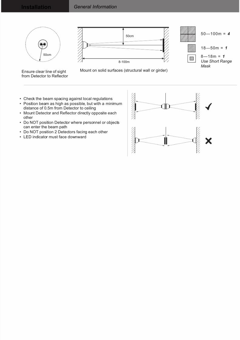
• Check the beam spacing against local regulations
• Position beam as high as possible, but with a minimumdistance of 0.5m from Detector to ceiling
• Mount Detector and Reflector directly opposite eachother
• Do NOT position Detector where personnel or objects
can enter the beam path• Do NOT position 2 Detectors facing each other
• LED indicator must face downward
18—50m = 1
50—100m = 4
8—18m = 1
Use Short Range
Mask
50cm
8-100m
50cm
Ensure clear line of sightfrom Detector to Reflector
Mount on solid surfaces (structural wall or girder)
50cm
50cm
8-100m
Page 2
8/8/2019 f5k Qsg English
http://slidepdf.com/reader/full/f5k-qsg-english 2/12
Wiring DiagramsInstallation
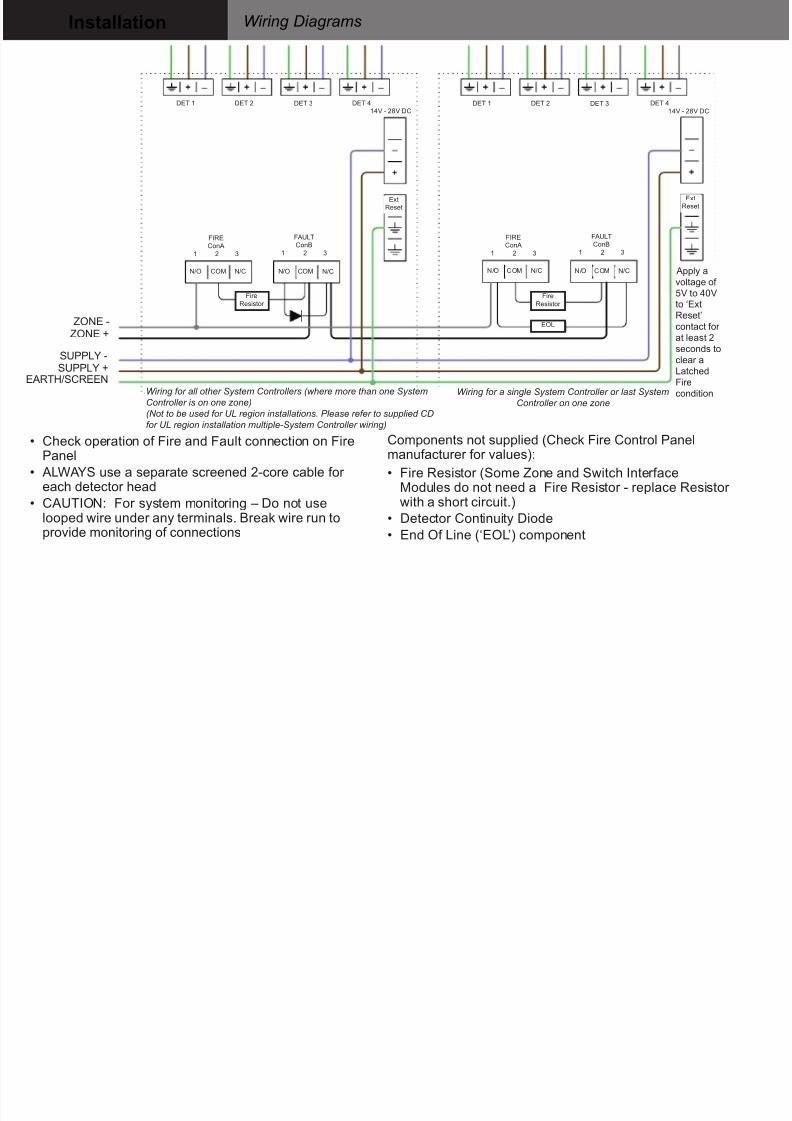
Wiring for all other System Controllers (where more than one System
Controller is on one zone)
(Not to be used for UL region installations. Please refer to supplied CDfor UL region installation multiple-System Controller wiring)
Wiring for a single System Controller or last System
Controller on one zone
ZONE -ZONE +
SUPPLY -SUPPLY +
EARTH/SCREEN
Components not supplied (Check Fire Control Panelmanufacturer for values):
• Fire Resistor (Some Zone and Switch InterfaceModules do not need a Fire Resistor - replace Resistor with a short circuit.)
• Detector Continuity Diode
• End Of Line (‘EOL’) component
• Check operation of Fire and Fault connection on FirePanel
• ALWAYS use a separate screened 2-core cable for each detector head
• CAUTION: For system monitoring – Do not uselooped wire under any terminals. Break wire run toprovide monitoring of connections
Apply avoltage of
5V to 40Vto ‘Ext
Reset’
contact for
at least 2
seconds to
clear a
Latched
Fire
condition
DET 1 DET 2 DET 3 DET 1 DET 2 DET 3 DET 4
14V - 28V DC
DET 4
14V - 28V DC
FIRE
ConA
1 2 3
N/O
Fire
Resistor
Fire
Resistor
Ext
Reset
Ext
Reset
EOL
COM N/C N/O COM N/C
FAULT
ConB
1 2 3
FIRE
ConA
1 2 3
N/O COM N/C N/O COM N/C
FAULT
ConB
1 2 3
Page 3
8/8/2019 f5k Qsg English
http://slidepdf.com/reader/full/f5k-qsg-english 3/12
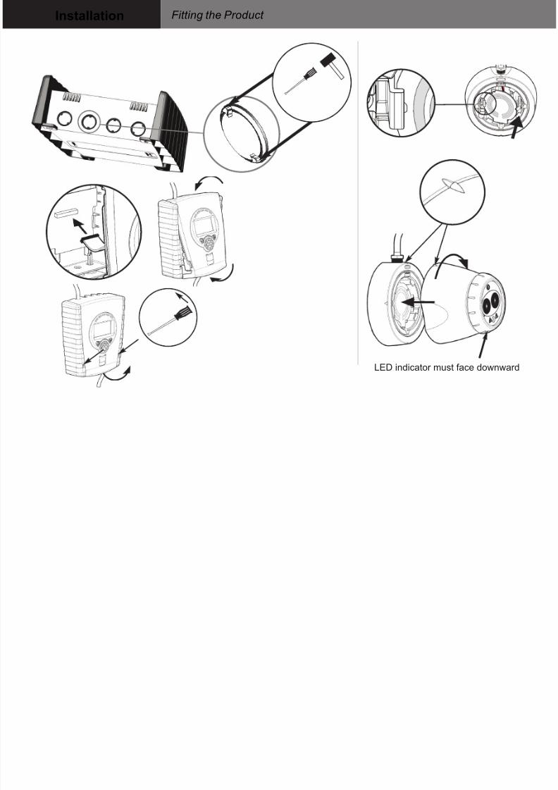
Fitting the Product Installation
LED indicator must face downward
Page 4
8/8/2019 f5k Qsg English
http://slidepdf.com/reader/full/f5k-qsg-english 4/12
Apply Power and Enter Pass CodeCommissioning
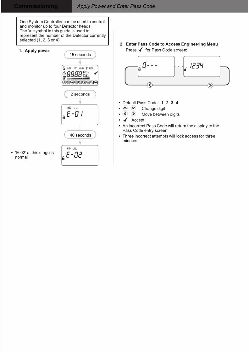
1. Apply power
• ‘E-02’ at this stage isnormal
2. Enter Pass Code to Access Engineering MenuPress for Pass Code screen:
2 seconds
15 seconds
40 seconds
• Default Pass Code: 1 2 3 4
• Change digit
• Move between digits
• Accept
• An incorrect Pass Code will return the display to the
Pass Code entry screen• Three incorrect attempts will lock access for three
minutes
One System Controller can be used to controland monitor up to four Detector heads.The ‘#’ symbol in this guide is used torepresent the number of the Detector currentlyselected (1, 2, 3 or 4).
Page 5
8/8/2019 f5k Qsg English
http://slidepdf.com/reader/full/f5k-qsg-english 5/12
Finding Detectors and Selecting Power ModeCommissioning
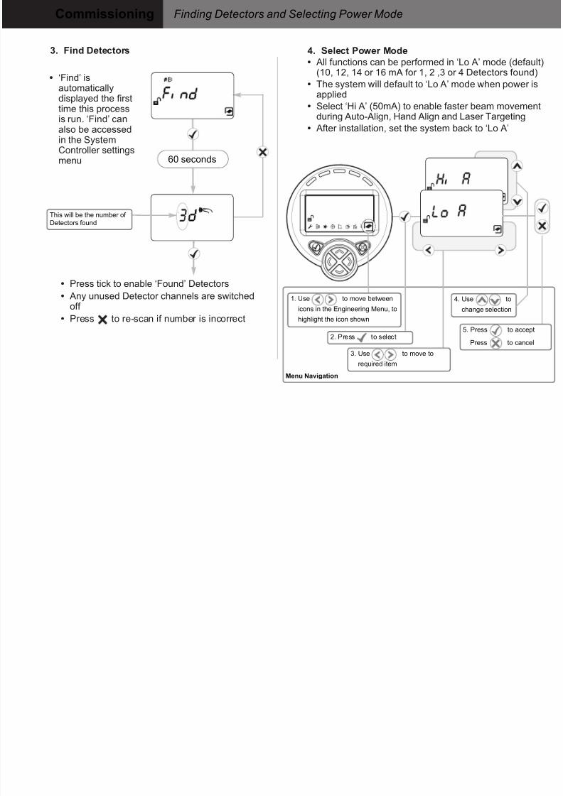
3. Find Detectors
60 seconds
• Press tick to enable ‘Found’ Detectors
• Any unused Detector channels are switchedoff
• Press to re-scan if number is incorrect
Menu Navigation
• All functions can be performed in ‘Lo A’ mode (default)(10, 12, 14 or 16 mA for 1, 2 ,3 or 4 Detectors found)
• The system will default to ‘Lo A’ mode when power is
applied• Select ‘Hi A’ (50mA) to enable faster beam movementduring Auto-Align, Hand Align and Laser Targeting
• After installation, set the system back to ‘Lo A’
4. Select Power Mode
1. Use to move between
icons in the Engineering Menu, to
highlight the icon shown
3. Use to move to
required item
2. Press to select
This will be the number of
Detectors found
4. Use to
change selection
5. Press to accept
Press to cancel
• ‘Find’ isautomatically
displayed the firsttime this processis run. ‘Find’ canalso be accessedin the SystemController settingsmenu
Page 6
8/8/2019 f5k Qsg English
http://slidepdf.com/reader/full/f5k-qsg-english 6/12
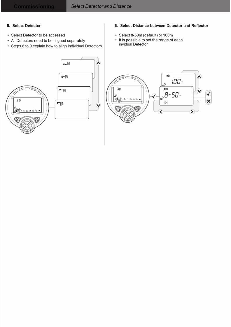
Select Detector and DistanceCommissioning
• Select 8-50m (default) or 100m
• It is possible to set the range of eachinvidual Detector
6. Select Distance between Detector and Reflector
• Select Detector to be accessed
• All Detectors need to be aligned separately• Steps 6 to 9 explain how to align individual Detectors
5. Select Detector
1
2
3
4
Page 7
8/8/2019 f5k Qsg English
http://slidepdf.com/reader/full/f5k-qsg-english 7/12
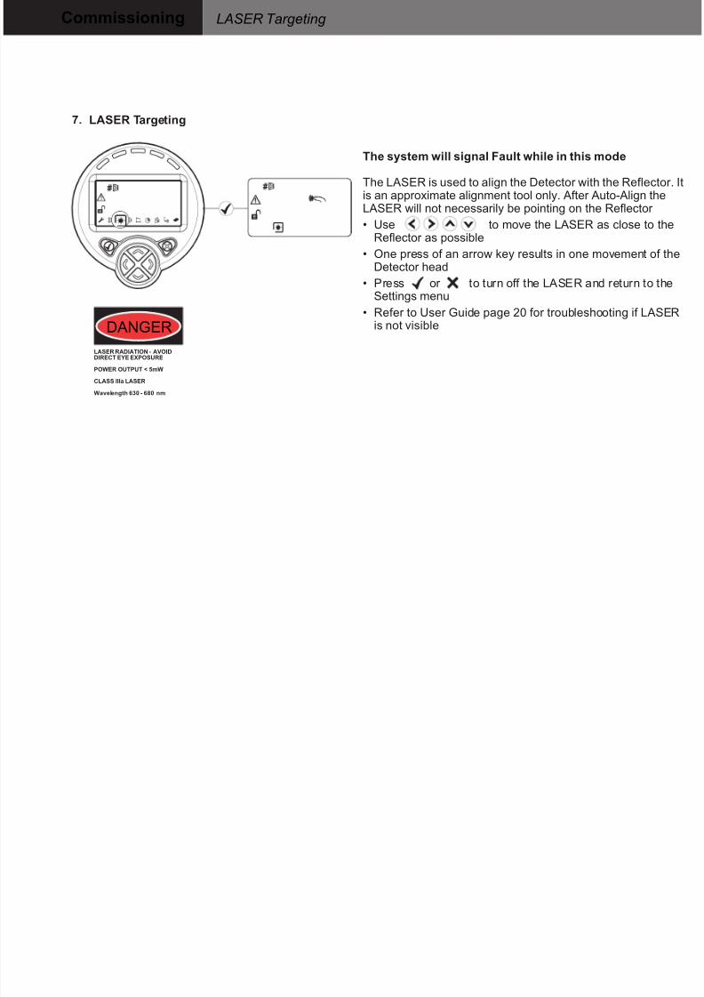
The system will signal Fault while in this mode
The LASER is used to align the Detector with the Reflector. Itis an approximate alignment tool only. After Auto-Align theLASER will not necessarily be pointing on the Reflector
• Use to move the LASER as close to theReflector as possible
• One press of an arrow key results in one movement of theDetector head
• Press or to turn off the LASER and return to theSettings menu
• Refer to User Guide page 20 for troubleshooting if LASERis not visible
LASER Targeting Commissioning
LASER RADIATION - AVOIDDIRECT EYE EXPOSURE
POWER OUTPUT < 5mW
CLASS IIIa LASER
Wavelength 630 - 680 nm
DANGER
7. LASER Targeting
Page 8
8/8/2019 f5k Qsg English
http://slidepdf.com/reader/full/f5k-qsg-english 8/12
Commissioning ‘Auto’ Alignment and ‘Set’ 0/100 (Calibrate)
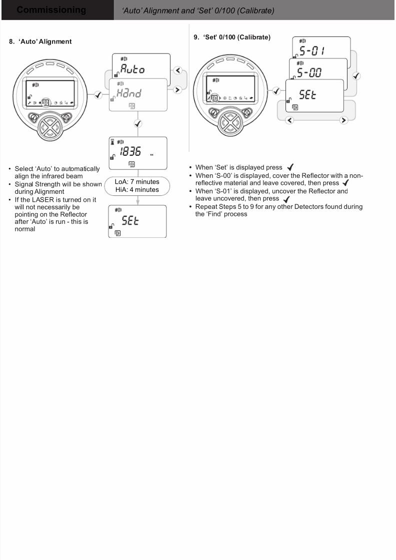
9. ‘Set’ 0/100 (Calibrate)
• Select ‘Auto’ to automaticallyalign the infrared beam
• Signal Strength will be shownduring Alignment
• If the LASER is turned on it
will not necessarily bepointing on the Reflector after ‘Auto’ is run - this isnormal
8. ‘Auto’ Alignment
• When ‘Set’ is displayed press
• When ‘S-00’ is displayed, cover the Reflector with a non-reflective material and leave covered, then press
• When ‘S-01’ is displayed, uncover the Reflector andleave uncovered, then press
• Repeat Steps 5 to 9 for any other Detectors found duringthe ‘Find’ process
LoA: 7 minutes
HiA: 4 minutes
Page 9
8/8/2019 f5k Qsg English
http://slidepdf.com/reader/full/f5k-qsg-english 9/12
Commissioning Alignment Status
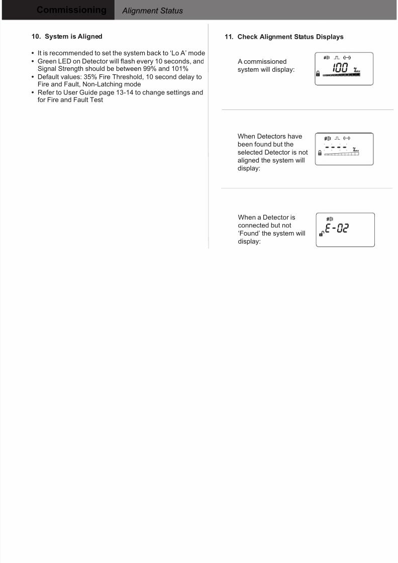
10. System is Aligned
• It is recommended to set the system back to ‘Lo A’ mode
• Green LED on Detector will flash every 10 seconds, and
Signal Strength should be between 99% and 101%• Default values: 35% Fire Threshold, 10 second delay to
Fire and Fault, Non-Latching mode
• Refer to User Guide page 13-14 to change settings andfor Fire and Fault Test
11. Check Alignment Status Displays
A commissioned
system will display:
When Detectors havebeen found but the
selected Detector is not
aligned the system will
display:
When a Detector is
connected but not
‘Found’ the system will
display:
Page 10
8/8/2019 f5k Qsg English
http://slidepdf.com/reader/full/f5k-qsg-english 10/12
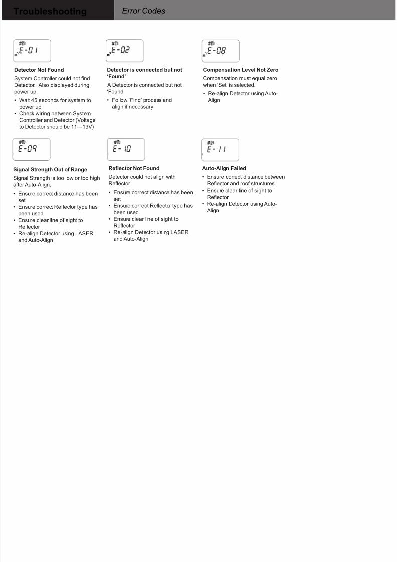
Troubleshooting Error Codes
Detector Not FoundSystem Controller could not find
Detector. Also displayed during
power up.
• Wait 45 seconds for system to
power up
• Check wiring between System
Controller and Detector (Voltage
to Detector should be 11—13V)
Detector is connected but not‘Found’
A Detector is connected but not
‘Found’
• Follow ‘Find’ process and
align if necessary
Compensation Level Not ZeroCompensation must equal zero
when ‘Set’ is selected.
• Re-align Detector using Auto-
Align
Signal Strength Out of Range
Signal Strength is too low or too high
after Auto-Align.
• Ensure correct distance has been
set
• Ensure correct Reflector type hasbeen used
• Ensure clear line of sight to
Reflector
• Re-align Detector using LASER
and Auto-Align
Reflector Not Found
Detector could not align with
Reflector
• Ensure correct distance has been
set
• Ensure correct Reflector type has
been used
• Ensure clear line of sight to
Reflector
• Re-align Detector using LASER
and Auto-Align
Auto-Align Failed
• Ensure correct distance between
Reflector and roof structures
• Ensure clear line of sight to
Reflector
• Re-align Detector using Auto-
Align
Page 11
8/8/2019 f5k Qsg English
http://slidepdf.com/reader/full/f5k-qsg-english 11/12
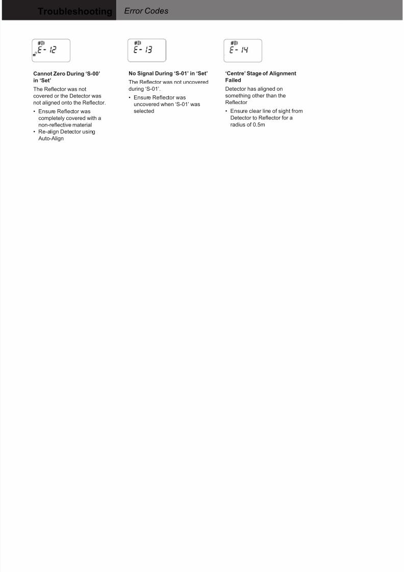
Troubleshooting Error Codes
Cannot Zero During ‘S-00’in ‘Set’
The Reflector was not
covered or the Detector was
not aligned onto the Reflector.
• Ensure Reflector was
completely covered with a
non-reflective material
• Re-align Detector using
Auto-Align
No Signal During ‘S-01’ in ‘Set’
The Reflector was not uncovered
during ‘S-01’.
• Ensure Reflector was
uncovered when ‘S-01’ was
selected
‘Centre’ Stage of AlignmentFailed
Detector has aligned on
something other than the
Reflector
• Ensure clear line of sight from
Detector to Reflector for a
radius of 0.5m
Page 12
8/8/2019 f5k Qsg English
http://slidepdf.com/reader/full/f5k-qsg-english 12/12
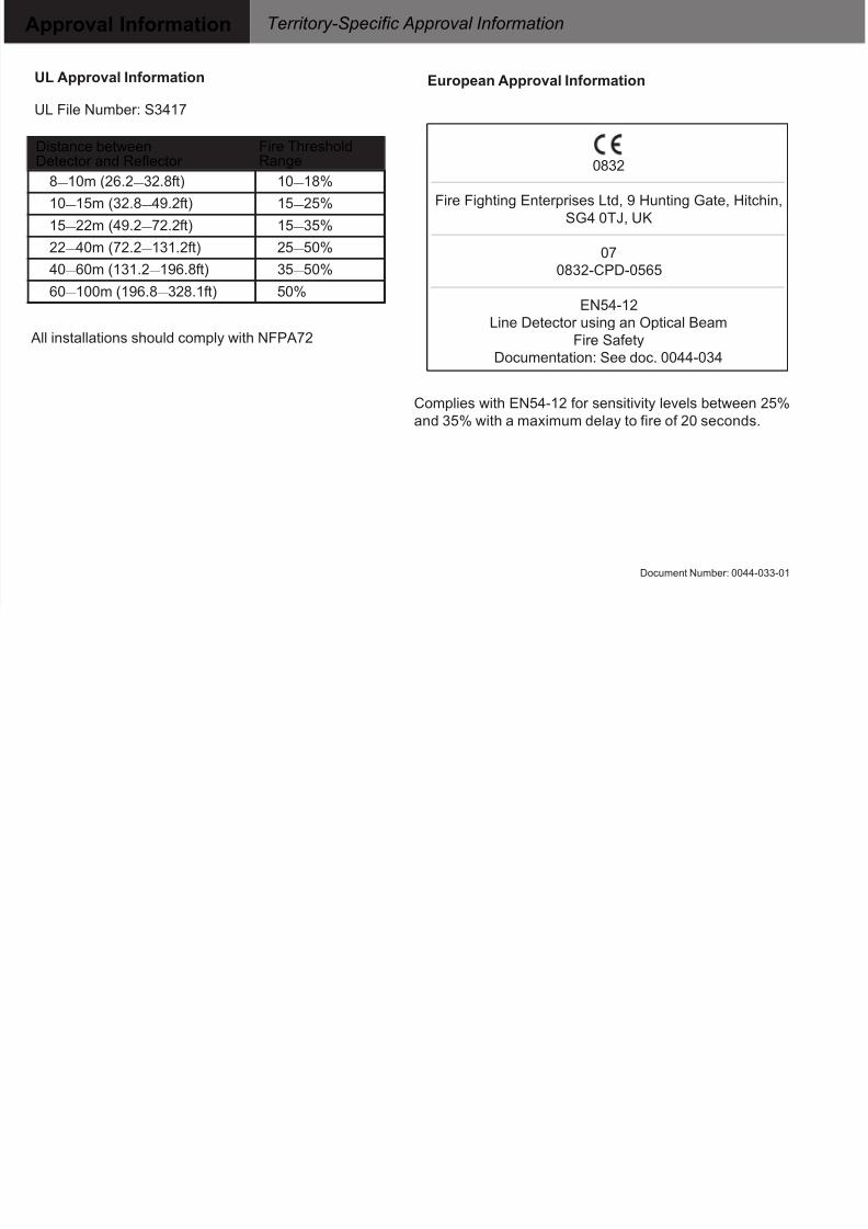
Approval Information Territory-Specific Approval Information
European Approval Information
Complies with EN54-12 for sensitivity levels between 25%
and 35% with a maximum delay to fire of 20 seconds.
UL Approval Information
UL File Number: S3417
0832
Fire Fighting Enterprises Ltd, 9 Hunting Gate, Hitchin,
SG4 0TJ, UK
07
0832-CPD-0565
EN54-12Line Detector using an Optical Beam
Fire Safety
Documentation: See doc. 0044-034
Distance betweenDetector and Reflector
Fire ThresholdRange
8—10m (26.2—32.8ft) 10—18%
10—15m (32.8—49.2ft) 15—25%
15—22m (49.2—72.2ft) 15—35%
22—40m (72.2—131.2ft) 25—50%
40—60m (131.2—196.8ft) 35—50%
60—100m (196.8—328.1ft) 50%
All installations should comply with NFPA72
Document Number: 0044-033-01