Page 1
FODHippo An Automated Debris Collection System for Airport Runways
FAA Design Competition for Universities 2012 Airport Operation and Maintenance Challenge
Team:
Clifford Bargar, William Langford, Jeffrey Prescott, Nicholas Stone
Tufts University Department of Mechanical Engineering, Undergraduates
Advisors:
Professor Gary Leisk, Professor Jason Rife, Professor Dan Hannon
Tufts University Department of Mechanical Engineering
April 25th, 2012
Page 2
ii
Executive Summary
The purpose of this report is to present our design for the FODHippo system, a distributed,
automated foreign object debris (FOD) removal system for airport runways.
FOD costs the airline industry over 12 billion dollars annually. In addition to causing
damage to aircraft, FOD is also a large source of air traffic delays, which are both a large
financial drain on airport operators and a nuisance to passengers. In order to reduce the danger
due to FOD and the related costs, we decided to develop a distributed, autonomous FOD
retrieval system.
By reviewing existing technologies, we established a baseline from which to work from.
Xsight Systems, for example, produces stationary sensors capable of detecting FOD on a runway
and determining its GPS coordinates. This system increases the ease of FOD detection but still
requires a human in the loop. Instead, we envision an autonomous system which could provide
faster reaction times in addition to off-peak preventative sweeps.
After meeting with officials at Boston Logan International Airport and consulting FAA
Advisory Circulars, we were able to derive a set of specifications for our envisioned system.
These specifications both provided a framework for our design process and a metric by which to
grade our results.
In executing and implementing our design, we developed two prototypes. The first
prototype focused on the FOD retrieval mechanism with an emphasis on enabling the removal of
objects the size of dead birds from runways. In contrast, the main focus of the second prototype
was GPS waypoint navigation, a requirement for autonomous FOD retrieval. Along with
physical prototypes, we addressed several systems level issues such as integrating this type of
device into existing airport operations as well as issues of how to effectively display and use data
obtained by the device.
One of the major steps required to implement a system like this at an airport is the safety
risk management (SRM) process. We first identified a number of hazards and then used FAA
guidelines to quantitatively examine the risks inherent in each. We also formulated ways to
mitigate these risks; namely, defining an “abort” protocol and GPS boundaries.
Communications with industry experts were critical to the design process and provided
an invaluable source of feedback; a description of industry interactions is also included in the
report.
Additionally, we evaluated the projected impact of our design. This takes the form of a
cost/benefit analysis in which we roughly calculated the cost of installing the proposed system in
an airport as well as the savings created by the system. We found that the $2M system pays for
itself after approximately one year from reductions in engine ingestion related damage ($1.6M)
and costs associated with delays ($700K).
The two prototypes collectively demonstrate much of the locomotion, communication,
FOD removal, FOD storage, and navigation functionalities required of the final product. Along
with the proposed additions, improvements, and operational strategies, we are confident that the
overall system will be able to provide both an increase in safety and a decrease in delays,
resulting in an annual savings of roughly $2.3 million for a large airport.
Page 3
iii
Table of Contents
Executive Summary ........................................................................................................................ ii
List of Figures ................................................................................................................................. v
List of Tables .................................................................................................................................. v
List of Definitions .......................................................................................................................... vi
List of Abbreviations, Acronyms, and Initialisms ........................................................................ vii
Background and Problem Statement ............................................................................................... 1
Summary of Literature Review ....................................................................................................... 2
Review of Existing Detection and Removal Systems................................................................. 2
Literature Review of Airport Operations Documents ................................................................. 4
Literature Review of GPS Navigation Techniques ..................................................................... 5
Problem Solving Approach ............................................................................................................. 6
Technical Aspects of the Design ................................................................................................... 10
First Prototype ........................................................................................................................... 11
Mechanical Design of First Prototype .................................................................................. 11
Hungry Hippo Mechanism Implementation in First Prototype ............................................ 13
Electronics Implementation in First Prototype ..................................................................... 14
Second Prototype ...................................................................................................................... 15
Mechanical Design of Second Prototype .............................................................................. 15
GPS Navigation with Second Prototype ............................................................................... 16
Operational Strategies ............................................................................................................... 20
“GPS Fence” Strategy ........................................................................................................... 20
FOD Report System .............................................................................................................. 21
Safety Risk Assessment ................................................................................................................ 23
Identification of Hazards and Risks .......................................................................................... 23
Treatment of Risks .................................................................................................................... 26
Interactions with Airport Operators and Industry Experts ............................................................ 28
Projected Impacts of Design ......................................................................................................... 30
Cost Benefit Analysis ............................................................................................................... 30
Commercial Viability................................................................................................................ 33
Conclusion .................................................................................................................................... 35
Appendix A - Contact Information ............................................................................................... 36
Appendix B - Description of Tufts University ............................................................................. 37
Appendix C - Description of Massport ......................................................................................... 38
Page 4
iv
Appendix D - Sign-off Form......................................................................................................... 39
Appendix E - Evaluation of Educational Experience ................................................................... 43
Appendix F - References .............................................................................................................. 49
Appendix G - FODHippo in Action.............................................................................................. 50
Appendix H - Additional Photos................................................................................................... 51
Appendix I - Links to Videos........................................................................................................ 52
Appendix J - Detailed Drawings (not to scale) ............................................................................. 53
Appendix K - Parts for First Prototype ......................................................................................... 56
Appendix L – Embedded GPS Navigation Code .......................................................................... 57
Page 5
v
List of Figures
Figure 1: FOD Finder reporting system .......................................................................................... 3 Figure 2: FOD*BOSS by Aerosweep ............................................................................................. 4 Figure 3: Schematic representation of system operating modes ..................................................... 7
Figure 4: Multi-view drawing of first prototype (all dimensions in inches)................................. 12 Figure 5: Comparison between SolidWorks model and actual prototype .................................... 13 Figure 6: Side view cross section showing path of support strut .................................................. 14 Figure 7: Front view cross section showing pulley system .......................................................... 14 Figure 8: Schematic representation of electronics subsystem ...................................................... 15
Figure 9: Two views of the second prototype ............................................................................... 15 Figure 10: Proportional heading controller ................................................................................... 17 Figure 11: Schematic representation of navigation control algorithm .......................................... 19
Figure 12: Possible path to FOD from nearest base station .......................................................... 20 Figure 13: Potential GPS fence regions ........................................................................................ 21 Figure 14: FOD locations and corresponding heatmap ................................................................ 22
Figure 15: Failsafe system ............................................................................................................ 27 Figure 16: Second Logan meeting; from left to right, Flavio Leo, Check Crescenzo, Nick Stone,
Vinnie Cardillo, and Will Langford .............................................................................................. 29
Figure 17: FODHippo on the runway at Logan Airport with FOD .............................................. 30 Figure 18: Projected 10-year financial breakdown ....................................................................... 34
List of Tables
Table 1: Mapping customer needs to specifications ....................................................................... 9
Table 2: Design specifications ........................................................................................................ 9
Table 3: Identified hazards and associated risks ........................................................................... 24
Table 4: Likelihood levels from FAA Safety Handbook .............................................................. 24 Table 5: Levels of severity ............................................................................................................ 25
Table 6: Levels of risk .................................................................................................................. 26 Table 7: Projected 10-year financial breakdown (thousands of dollars) ...................................... 34
Page 6
vi
List of Definitions
Acme A trapezoidal screw thread profile.
Arduino An open-source low-cost single-board microcontroller.
Autonomous Acting independently or having the freedom to do so.
Incursion Any unauthorized intrusion onto a runway, regardless of whether or not
the aircraft presents a potential conflict.
Massport The port authority in the Commonwealth of Massachusetts that owns and
operates Boston Logan International Airport as well as several other
transportation facilities.
Odometry The use of motor encoders to determine a robot's change in position and
orientation relative to some previous position.
SolidWorks A 3D computer aided design program.
Tetrix A design system for construction using aluminum elements created by
Pitsco.
Timing belt A rubber belt with teeth used to transmit torque.
Leadscrew A screw designed to translate rotational motion into linear motion.
Waypoint navigation The process or activity of accurately ascertaining one's position and
planning and following a route using reference points in physical space.
Page 7
vii
List of Abbreviations, Acronyms, and Initialisms
ADS-B A NextGen surveillance technology for tracking aircraft
FAA Federal Aviation Administration
FOD Foreign Object Debris
GPS Global Positioning System
SRM Safety Risk Management
Page 8
1
Background and Problem Statement
Foreign object debris, or FOD, is a major safety issue at airports. A variety of objects frequently
find their way onto airport runways where they can be ingested into jet engines or otherwise
cause serious damage to aircraft. This resulting damage to the engine, body, or landing gear of an
aircraft can lead to passenger injuries or even fatalities. The most common sources of debris
are various tools, which can be misplaced by mechanics, and dead birds, which can get caught up
in planes’ wakes. Objects range in size from as small as nuts and bolts to as large as a suitcase. In
fact, FOD costs the airline industry over 12 billion dollars every year. [1]
While damage caused by FOD, either via engine ingestion or collision with the aircraft,
amounts to a significant portion of this total (in parts, labor, and other repair costs), there are
many indirect costs as well. One of the most expensive byproducts of FOD is the cost of delays;
when FOD damage occurs, it not only delays the damaged plane, but also slows down all flights
scheduled to take off or land on that runway (and potentially others, as well). In addition to the
time required for the plane to exit the runway, the need to perform repairs, testing, and possibly
change planes quickly adds up to a large decrease in efficiency. In 2000, a piece of FOD that
went unnoticed on the runway at Charles de Gaulle International Airport resulted in the crash of
an Air France Concorde, resulting in the deaths of 113 people. [2] To avoid similar tragedies,
airport personnel must shut down the runway and mobilize to remove FOD as soon as it is found,
thereby further contributing to delays.
In order to prevent aircraft damage and maintain safety and efficiency, runways must be
kept free of FOD while aircraft are operating. To accomplish this, they are checked regularly by
airport personnel and are also monitored by pilots who check the runways as they take off and
land. Many airports have also begun to implement automated detection systems to ensure that no
Page 9
2
FOD goes unnoticed. Boston Logan International Airport, for example, is working with Xsight
Systems, based in Israel, to install their FODetect system along one of the runways.1 [3]
In order to remove FOD from a runway, the runway must be shut down, preventing any
aircraft from taking off or landing. Only once the runway is entirely clear of traffic can a worker
proceed to the location of the FOD and remove it manually. This can be both a time consuming
and manpower intensive process. Additionally, any time a person goes out onto the runway there
are a number of risks involved, including interrupting traffic on another runway or leaving
potential FOD behind.
Our goal is to develop an autonomous FOD removal system, which will ultimately
increase the safety of airports and decrease the time commitment and cost required to execute
FOD removal procedures. We focused on autonomous removal rather than detection due to the
existence of several advanced detection systems currently in development. [3]
Summary of Literature Review
Review of Existing Detection and Removal Systems
As part of the literature review, we studied existing state-of-the-art technologies used for FOD
detection and removal. One report, “Performance Assessment of a Mobile, Radar-Based Foreign
Object Debris Detection System,” details the performance of the FOD Finder, a mobile FOD
detection system used at Chicago O’Hare International Airport. The FOD Finder is a radar-based
detection system that can be mounted on a vehicle or truck; it is capable of scanning an 80o area
1 Logan Airport is used as an example throughout the report both because it’s representative of
many high volume airports across the country and because of our opportunity to meet with
officials there.
Page 10
3
200 m in front of the vehicle while traveling up to and exceeding speeds of 30 mph. The FOD
Finder successfully identified 195 of 195 target objects both on and off airport runways while
traveling at 15 mph. The target objects in this case were metal cylinders 1 inch tall with a 0.94
inch diameter (as defined in AC 150/5220-24). The system is also capable of determining the
location of detected objects using its onboard differential GPS system with an accuracy between
2 and 13 feet. A vacuum can be mounted to the rear of the vehicle to facilitate the removal of any
FOD that is detected. In addition to detection and removal, the FOD Finder supports data
management and assessment through its FOD reporting system which overlays identified FOD
onto a map of the airport after each inspection; this kind of inspection report can be seen in
Figure 1 where the red dots represent FOD that has been detected and collected at some point.
[4]
Figure 1: FOD Finder reporting system
There are also stationary systems with similar capabilities, such as Xsight Systems’
FODetect and FODspot. These systems are integrated into the existing infrastructure for runway
edge lights, requiring little additional infrastructure and placing them in a prime location safely
Page 11
4
out of harm’s way. The system is capable of not only detecting FOD, but also classifying it and
determining its exact coordinates. [3]
A large variety of FOD removal technologies currently exist and range from passive
collection systems to active sweeping and suction systems. The FOD*BOSS by Aerosweep is a
passive debris collection system that uses friction and a series of angled brushes to trap and hold
FOD in a mesh sheet as it is dragged over the tarmac. It can be attached to any airport vehicle
and can be swept at speeds up to 25 mph. Since it has no moving parts, it is easy to maintain and
is relatively reliable and robust. [5]
Figure 2: FOD*BOSS by Aerosweep
Literature Review of Airport Operations Documents
FAA Advisory Circulars were invaluable resources in defining specifications for airport
operations and for the system as a whole. Four FAA Advisory Circulars were particularly
informative: “Airport Safety Self-Inspection” (150/5200-18C), “Airport Foreign Object Debris
(FOD) Detection Equipment” (150/5220-24), “Introduction to Safety Management Systems
(SMS) for Airport Operators” (150/5200-37), and “Airport Foreign Object Debris (FOD)
Management” (150/5210-24). [6] [7] [8] [9]
Page 12
5
The “Airport Foreign Object Debris (FOD) Detection Equipment” Advisory Circular
serves as a baseline set of specifications for our detection and removal system. The specifications
for a mobile radar-based detection system, for example, are that it should scan “an area 600 ft by
600 ft . . . to detect FOD items measuring 1.2 in (3.0 cm) high and 1.5 in (3.8 cm) in diameter . . .
[and] operate at speeds of up to 30 mph (50 km/h).” [6] The document also mandates that
detection equipment be able to specify the location of detected FOD within 16 feet, which
translates to a minimum accuracy for our GPS waypoint navigation system.
In conducting a safety risk assessment of our system both the “Introduction to Safety
Management Systems (SMS) for Airport Operators” and “Airport Safety Self-Inspection” served
as valuable models of ways to systematically approach the Safety Risk Management (SRM)
process. Chapter 3 of the FAA System Safety Handbook also helped in a similar way. In
particular, it helped to quantitatively classify the likelihood and qualitatively classify the severity
of a given safety risk.
Literature Review of GPS Navigation Techniques
We studied a number of academic papers on the use of GPS localization to aid in the
implementation of our navigation system. The papers we reference focus primarily on the fusion
of GPS and odometry data to achieve more accurate localization and positioning than the 16 foot
resolution of a typical GPS unit. Thrapp et. al. present an implementation of an extended Kalman
filter used to aid in the precise positioning of an autonomous campus tour guide at Rice
University. Using their approach, the robot is able to remain within 40 centimeters of the desired
route. [10] Ohno et. al. used a similar extended Kalman filter method to correct for drift in
Page 13
6
odometry data and were able to achieve a positioning accuracy of 150 cm over a 240 m path.
[11]
Problem Solving Approach
In accordance with its large impact on airport operations, many technologies have been
developed to help airport operators detect and remove FOD. However, none of these solutions,
be they autonomous FOD detection networks or debris sweeping truck trailers, address the fact
that a human is ultimately needed to go out on the runway and retrieve the debris. Consequently,
there is potential for an autonomous system to drastically reduce the lag time between FOD
detection and removal, thus reducing the annual financial loss from FOD. For this reason, we
chose to begin development of a system with these capabilities, which we have named
FODHippo.
The project goal is to effectively and efficiently integrate existing detection technologies
with our autonomous FOD retrieval system and to do so in a way that maximizes efficiency,
minimizes downtime, and reduces safety hazards. To be successful, our system must be capable
of working in concert with these existing detection systems, making FOD detection and removal
an almost fully automated process. The final system will be distributed in nature, consisting of
many individual autonomous robots per airfield. Each robot will be able to receive GPS
coordinates of FOD, navigate to that location, locate the object, and remove it without human
interaction. As a preventative measure, the system will also be able to search runways and
taxiways that aren’t in use for foreign objects. The processes involved in executing these two
primary capabilities are shown in Figure 3 below.
Page 14
7
Figure 3: Schematic representation of system operating modes
.
During the design and implementation of the FODHippo system, which is named for the
‘Hungry Hippo’ mechanism described in the Technical Aspects section of this report, three
factors played a major role in every decision: safety, financial viability, and FAA specifications.
In order to ensure that the FODHippo would meet or exceed all consumer and regulatory
expectations, we created an extremely detailed set of specifications early in the design process.
Page 15
8
Another step we took to simplify the design process was to divide the project into a series of
subsystems which could be designed and implemented individually. This allowed for the
creation of specifications which only concerned certain portions of the project and prototypes
which only tested certain capabilities of the envisioned final device.
In order to develop an appropriate set of specifications it was first necessary to gain a
deeper understanding of the needs of airport administrators. To accomplish this, we met several
times with Professor Dan Hannon, Robert Lynch, and Flavio Leo. Prof. Hannon is a Professor of
the Practice in the Tufts University Department of Mechanical Engineering who works with both
the U.S. Department of Transportation and the FAA whereas Mr. Lynch and Mr. Leo both work
for Massport and are responsible for administering Boston Logan International Airport.2
Conversations with these experts, in addition to information gleaned from FAA advisory
circulars, led to the development of a collection of customer needs, shown in Table 1.
In order to ensure that the final implementation would meet the industry experts' stated
needs, these needs were translated into metrics which could be used to evaluate the performance
of a prototype. This mapping is illustrated in Table 1. Next, a set of detailed design specifications
was developed by assigning required values and importance levels (1 to 3, with 3 being deemed
most important) to all of the metrics, as shown in Table 2.
2 Further details are available in the Interactions with Airport Operators section below.
Page 16
9
Table 1: Mapping customer needs to specifications
Table 2: Design specifications
Page 17
10
Once we successfully formulated the project specifications, we divided the overall project
into subsystems to allow for modular implementation and testing. We split the system into seven
components: (1) locomotion, responsible for moving the robot, (2) control/electrical, responsible
for communication and coordination of other systems, (3) navigation, responsible for path
planning and positioning, (4) detection, responsible for identification and precise localization of
FOD, (5) collection, responsible for removing debris from the airport surface, (6) interface,
responsible for facilitating human control and monitoring of the device, and (7) base station,
responsible for charging the robot and housing both the robot and collected FOD.
Technical Aspects of the Design
We decided to build a first prototype that focused on the implementation of the locomotion,
control and collection subsystems, which were seen as the most task-critical. We chose a
relatively small (two feet by two feet square) size scale for the first robot for several reasons. The
first was cost and ease of fabrication; because we could accomplish a proof-of-concept
implementation of the targeted subsystems at this scale we opted not to build a more expensive
larger scale prototype. Another concern was safety; if the prototype had been close to the size of
the envisioned final product (approximately 5 feet long) any loss of control during testing could
have had dangerous consequences. After the first prototype was built and tested, a second
prototype of similar scale was fabricated, this time focusing on the navigation subsystem.
Looking forward, we envision a future prototype which combines the capabilities of the first two
robots and implements a detection subsystem. This future prototype will also have a
weatherproof and more robust mechanical design with scaled up dimensions. The design will
Page 18
11
include a separate base station housing where the robot will return to recharge and unload FOD
during inactive periods.
While the design, manufacturing, and testing of the robots themselves were our main
focus, a significant effort was made to solve relevant problems on both the systems and
operations levels. This has resulted in a detailed outline of how we believe the final product
should be operated as well as a summary of the various benefits the device would bring to
airports. In addition, a detailed cost analysis was performed to demonstrate the financial viability
of the project.
First Prototype
Mechanical Design of First Prototype
Our first prototype implemented a retrieval mechanism, a locomotion system, and wireless
control. A full design was drawn up in SolidWorks before we machined the prototype from stock
parts in the Tufts Mechanical Engineering Department’s Bray machine shop. This prototype
removes FOD from the runway with a mechanism used to ingest objects. Due to the motion of
the retrieval process, we have given the name “Hungry Hippo” to the mechanism, which is
described in more detail below. Additionally, the robot can lower its front ramp using a servo
motor to bridge the gap between the ground and the floor of the device. With the ramp lowered,
the Hungry Hippo mechanism can be deployed to collect the FOD. This process is controlled
remotely; it is further illustrated in a series of photos in Appendix H.
The frame of the robot was fabricated using aluminum plates and U-channels while the
floor of the robot and the majority of the Hungry Hippo mechanism is composed of acrylic. The
Acme leadscrews and matching threaded blocks used to provide linear translation of the
Page 19
12
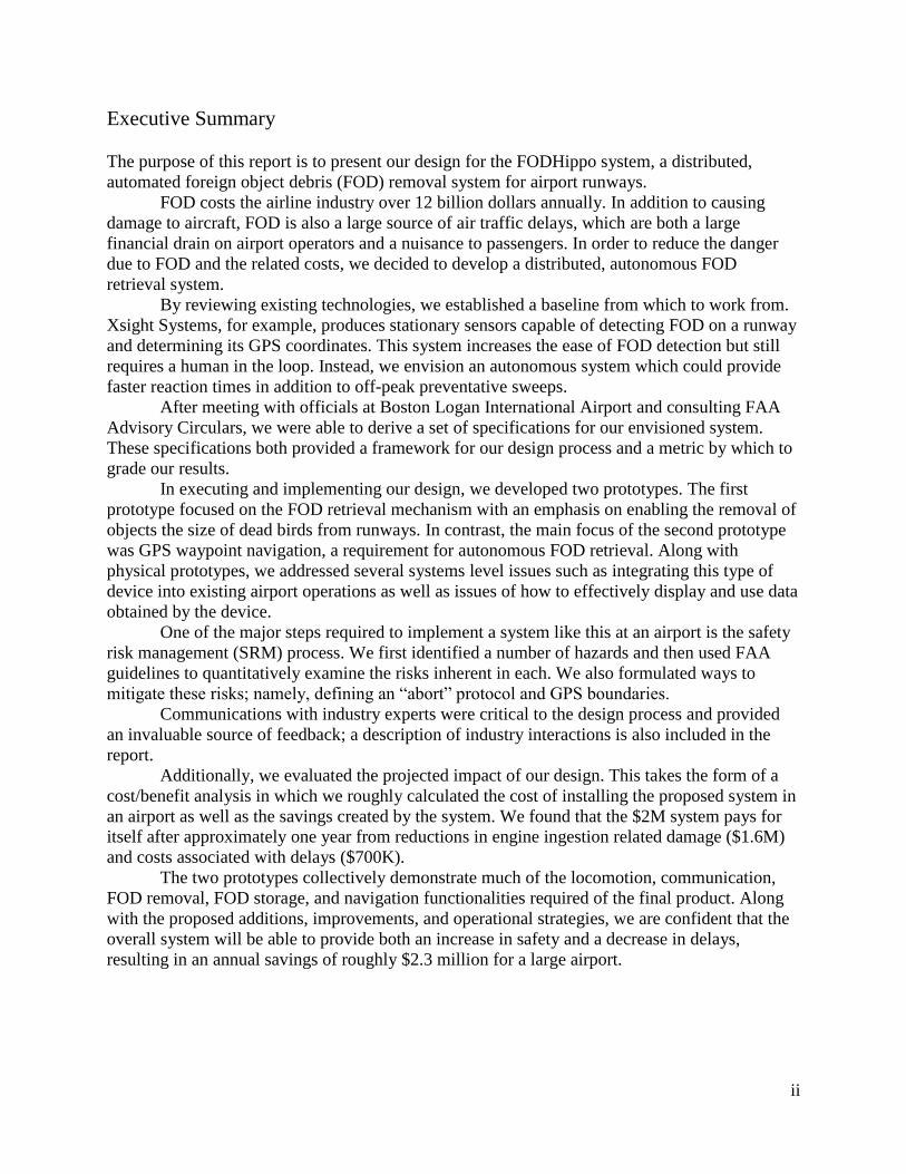
mechanism are made of steel and aluminum, respectively. The complete assembly is pictured in
Figure 4.
Figure 4: Multi-view drawing of first prototype (all dimensions in inches)
The components which make up this prototype were machined by referencing detailed
drawings generated by a comprehensive SolidWorks model, which was also used as a
construction guide. As evidenced by Figure 5, the final device is essentially identical to the
model. More detailed drawings for the first prototype can be found in Appendix J. The list of
parts is in Appendix K.
Page 20
13
Figure 5: Comparison between SolidWorks model and actual prototype
Hungry Hippo Mechanism Implementation in First Prototype
The mechanism has one degree of freedom and is designed to capture large sized FOD by
actuating an acrylic box to encapsulate the target object and bring it back into the chassis. This
motion is accomplished with the use of one actuator: a motor attached to a timing belt. This belt
drives two Acme leadscrews which push the box’s supports along rails. The geometry of these
rails, which incorporate a hinge, defines the motion of the box, as shown in Figure 6.
The pulley system was chosen to utilize a 350 tooth, 9 millimeter wide timing belt to
transmit torque from the motor shaft positioned in the center of the chassis to the two leadscrews
in the side channels, as shown in Figure 7. A 1:1 gear-ratio ensures that the 300 ounce·inch
(stall) of torque generated by the motor is delivered to the leadscrews at close to the nominal
shaft speed of 154 revolutions per minute. Given the specifications of our chosen motor, it was
important to choose the proper leadscrews to turn rotational speed/torque into linear motion. An
Acme leadscrew with 5-starts was chosen to allow 1 inch of travel per revolution of the shaft.
This allowed the mechanism to travel its full stroke of 34 inches in under 15 seconds.
Page 21
14
Figure 6: Side view cross section showing path of support strut
Figure 7: Front view cross section showing pulley system
Electronics Implementation in First Prototype
The electronics used to control the various actuators onboard the robot were also key to the
success of the prototype. An Arduino microcontroller was responsible for translating user
commands into control signals and operating the actuators using a pair of motor drivers, a Pololu
MD03A and a Sparkfun DEV-09213. We selected these motor drivers based upon the stall
current of connected actuators; the Pololu device was responsible for controlling the relatively
high current Pololu motors that drive the wheels while the Sparkfun device was responsible for
control of the lower current Hungry Hippo actuator. The onboard electronics communicate with
the operator using a Pololu Wixel wireless device. The system is mapped out in Figure 8 below.
Page 22
15
Figure 8: Schematic representation of electronics subsystem
Second Prototype
Mechanical Design of Second Prototype
The second prototype was constructed as a demonstration of the navigation capabilities. The
body was primarily constructed from Pitsco Tetrix structural members, using the same wheels
and motors as the original prototype. This lighter chassis enabled the team to focus directly on
the issue of autonomous navigation with a faster robot by leaving out the capture mechanism.
This second prototype can be seen pictured below in Figure 9.
Figure 9: Two views of the second prototype
Page 23
16
To guide the robot to an already located piece of FOD, a set of waypoints can be chosen
that both direct the robot to its ultimate location and keep it from wandering to parts of the
airport that are off-limits, such as active runways and taxiways. The team selected an EM-
406A GPS module to provide the robot with a means for self-localization. Using a combination
of GPS readings and motor encoders, the robot can navigate from waypoint to waypoint.
GPS Navigation with Second Prototype
In order to allow the robot to navigate autonomously using GPS, a simple and effective control
system was devised based upon path linearization and proportional heading control. In the final
implementation, the location of FOD will be provided to the device in the form of a GPS
coordinate. A map of the airport annotated with the locations of taxiways, runways, and other
important landmarks will then be used to plot a safe and efficient path to the debris. This path
will then be discretized by splitting it into a collection of waypoints. Therefore, in order to follow
the prescribed path, the robot must simply remain pointed towards the next waypoint. A control
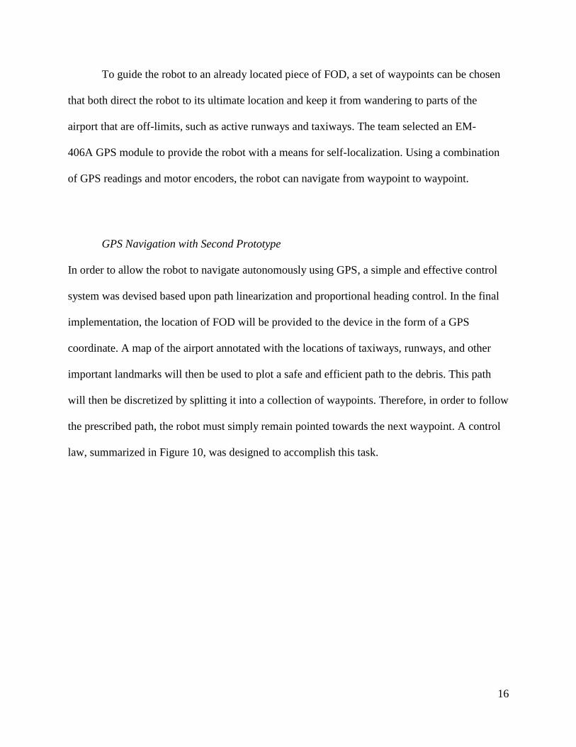
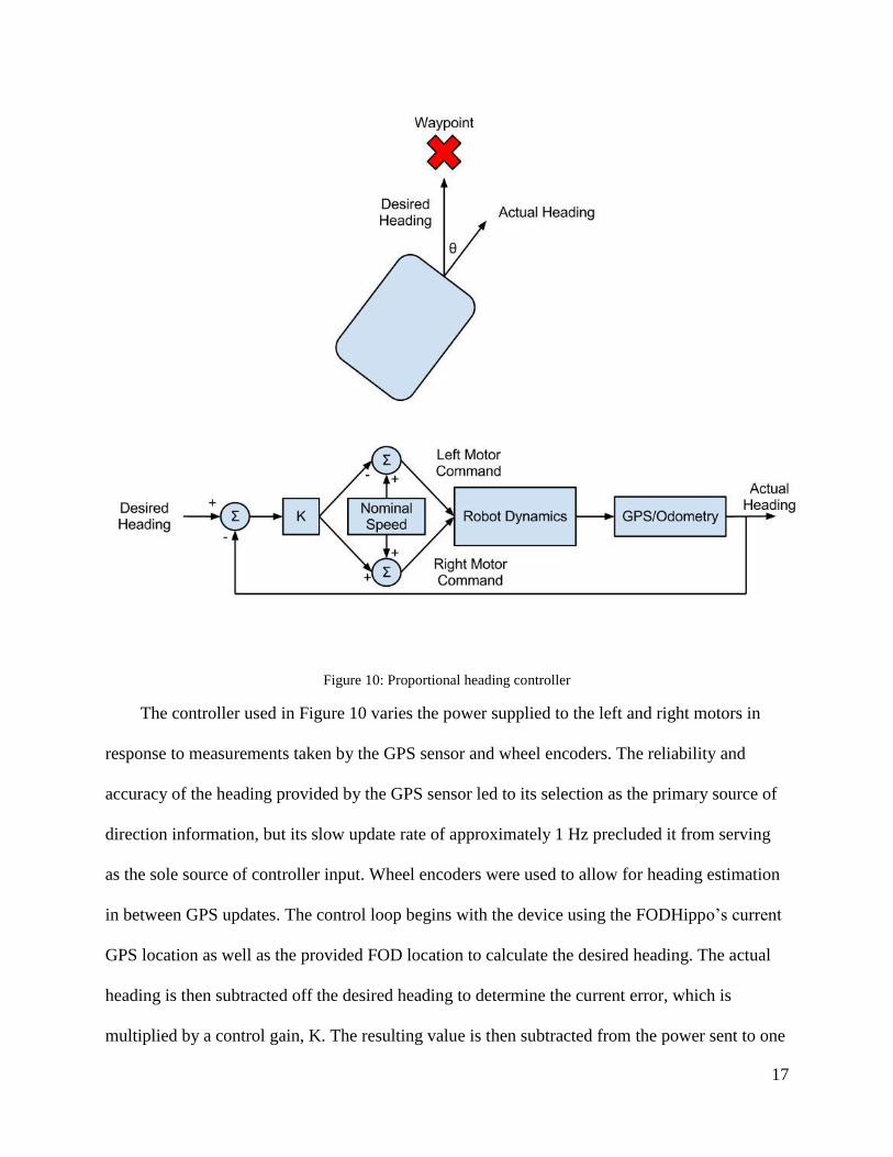
law, summarized in Figure 10, was designed to accomplish this task.
Page 24
17
Figure 10: Proportional heading controller
The controller used in Figure 10 varies the power supplied to the left and right motors in
response to measurements taken by the GPS sensor and wheel encoders. The reliability and
accuracy of the heading provided by the GPS sensor led to its selection as the primary source of
direction information, but its slow update rate of approximately 1 Hz precluded it from serving
as the sole source of controller input. Wheel encoders were used to allow for heading estimation
in between GPS updates. The control loop begins with the device using the FODHippo’s current
GPS location as well as the provided FOD location to calculate the desired heading. The actual
heading is then subtracted off the desired heading to determine the current error, which is
multiplied by a control gain, K. The resulting value is then subtracted from the power sent to one
Page 25
18
motor and added to the other, resulting in rotation in the opposite direction of the error with no
change in the vehicle’s speed. The complete navigational algorithm is illustrated schematically in
Figure 11.
The final version of the system would also include an additional fail-safe GPS system
capable of shutting down the entire robot that will operate on a separate communication line and
from its own power. This system would be similar to ADS-B (the FAA’s NextGen “Automatic
Dependent Surveillance-Broadcast” system currently being installed in aircraft) in that it would
broadcast the robot’s position, velocity, and identification information. [12] This would allow
for the system’s operator (or some central computer) to shut down the robot if its primary GPS
malfunctions and it strays from its intended path.
Page 26
19
Figure 11: Schematic representation of navigation control algorithm
Page 27
20
Operational Strategies
The FODHippo system will integrate seamlessly with current airport operations. Robot base
stations will be scattered throughout the airfield, allowing rapid response to FOD across all
airport surfaces, as shown in Figure 12.
Figure 12: Possible path to FOD from nearest base station
“GPS Fence” Strategy
In order to constrain the waypoint navigation of the robot, the system would include a virtual
“GPS fence.” The fence defines regions in which the robot is (or is not) safe to operate. There are
three types of regions: “safe” regions, “neutral” regions, and “off-limits” regions. A safe region
is one in which the robot is free to operate. The robot must still avoid other vehicles but is free to
roam anywhere in the safe region. The robot must not operate in an off-limits region. If the robot
is in an off-limits region there is a good probability that the robot has caused an incursion and it
will be shut-down immediately. The neutral regions demarcate the borders between the safe
regions and the off-limits regions. The neutral region provides a buffer-zone in the event of a
Page 28
21
navigation error. If a robot starts to wander too close to an active runway, for example, the
neutral region gives the fail-safe GPS system time to re-route or shut down the robot before it
causes an incursion.
The left side of Figure 13 shows an example of potential GPS fence regions at Boston
Logan International Airport in which the runways are marked as off-limits, the taxiways and the
stand are safe regions, and the border between safe and off-limits regions is neutral. The right
side represents GPS fence regions in which the robot is allowed to move anywhere on the
tarmac. This case might occur at low traffic times between aircraft movements.
Figure 13: Potential GPS fence regions
FOD Report System
We have prototyped a FOD report system to effectively compile and communicate all of the data
that is collected during a FOD identification and retrieval run. The system stores every instance
of FOD that is detected along with its latitude and longitude, time of detection, time of removal,
and type of debris. The data is then overlaid on a map of the airport runway, as shown in Figure
Page 29
22
14. By combining each set of data together, the system generates a virtual “heatmap” that
visually depicts where on the runway FOD is most often found. Displaying the data in this way
has two primary benefits. First, it provides an easy to understand view of all FOD occurrences.
Second, it gives maintenance operations information regarding possible areas of the runway that
might be degrading and becoming sources of FOD, allowing for more informed maintenance
planning and for smarter placement of the robots’ base stations.
Figure 14: FOD locations and corresponding heatmap
Page 30
23
Safety Risk Assessment
Identification of Hazards and Risks
As part of the Safety Risk Management (SRM) process we conducted a safety risk assessment in
order to identify potential hazards of our autonomous mobile FOD removal system. For each
identified hazard, we found a number of associated risks, each with some severity and likelihood
of occurring; the combination of the severity and likelihood determine the “level of risk” of a
particular hazard.
Table 3 is a compiled list of the identified hazards and risks associated with
implementing our autonomous FOD removal system. We’ve identified seven primary hazards;
furthermore, we have assigned a certain probability, or likelihood of occurrence, to each hazard.
Under each hazard, we determined that there are certain risks ranging from airport delays to
catastrophic crashes. Each risk has its own associated probability given the specific hazard. The
equivalent probability of a certain risk occurring is calculated by multiplying the probability of
the hazard by the probability of the risk. For example, we have assigned the hazard of the robot
creating FOD a probability of 1 in 100,000 (or 10-5
). The probability of a delay occurring given
that the robot has created FOD is on the order of 1 in 10 (or 10-1
). Therefore, the equivalent
probability of a delay occurring due because the robot created FOD is 10-1
*10-5
= 10-6
(or 1 in
1,000,000). This equivalent probability maps to a set of discrete likelihoods defined by the FAA
Safety Handbook, which are shown in Table 4. The FAA Safety Handbook also defines levels of
severity, which are shown in Table 5.
Page 31
24
Table 3: Identified hazards and associated risks
Table 4: Likelihood levels from FAA Safety Handbook
Page 32
25
Table 5: Levels of severity
Finally, the equivalent probability or likelihood can be combined with the severity of a
particular risk in order to get an overall “level of risk.” The “level of risk” has three discrete
levels: low risk, medium risk, and high risk. A high risk level is an “unacceptable level of risk.”
A proposal that contains a high risk level cannot be implemented until it is reduced to a lower
level. A medium risk level is an “acceptable level of risk” and is the minimum acceptable safety
objective. A proposal with a medium risk level may be implemented but it must be tracked and
managed to ensure it remains at an acceptable level of risk. A low risk level is the target level of
risk and is acceptable without restriction or limitation. Table 6 from the AC 150/5200-37
(“Introduction to Safety Management Systems (SMS) for Airport Operators”) defines the levels
of risk in terms of likelihood and severity. [8]
Page 33
26
Table 6: Levels of risk
Treatment of Risks
Having identified hazards and associated risks, we developed risk treatments to mitigate the risks
and manage the hazards. We focused primarily on the medium risk levels since the low
risk levels are generally acceptable. Our risk treatment strategies fall into two main categories:
technical fail-safes and operational and managerial strategies.
Technical fail-safes mitigate the chance of the robot becoming a hazard due to a fault. For
example, a redundant onboard GPS sensor, which operates on a separate power supply, would
reduce the risk associated with the primary GPS sensor malfunctioning and causing the robot to
violate a GPS fence, possibly causing an incursion. Along the same line, including a neutral zone
between “safe” areas and “off-limits” areas would greatly reduce the chance of the robot
accidentally causing an incursion. To mitigate the risks associated with losing control of the
robot, we decided to employ a fail-safe “abort” system. An onboard master kill switch, which
Page 34
27
can cut power to the main robot, broadcasts a unique identifier on its own radio channel; if, for
whatever reason, the main control station (off-board) loses contact with the master kill switch,
the system attempts to power down the main robot via the main controller. If that is unsuccessful,
the master kill switch activates and cuts the main power, thereby stopping the robot. This process
can be seen in the flowchart in Figure 15 below.
Figure 15: Failsafe system
A number of steps can also be taken on the operations side to better mitigate and treat risks
as they occur. For example, properly training maintenance staff on how to quickly removing
robots from the airfield would greatly reduce the risk of catastrophic failures.
Page 35
28
Interactions with Airport Operators and Industry Experts
Our first interaction with an industry expert came in the form of a discussion with Professor Dan
Hannon on September 23, 2011. During this discussion, Professor Hannon talked to us first
about his own experiences with Massport and the Department of Transportation and then went
on to outline a number of airport operational procedures and the various issues faced.
We met directly with representatives of Massport at Boston Logan International Airport
in Boston, MA on November 10, 2011 and March 26, 2012 and also had some email
correspondence.
Our first meeting with Massport was during the early stages of project planning and design
and consisted of a general overview of the project goals and a discussion breaking down the
functions of the airport. We spoke with Robert Lynch, the Airport Operations Manager, and
Flavio Leo, the Manager of Aviation Planning, who were able to inform us about how often the
airport encounters issues with foreign object debris (FOD) and how they handle the issues. After
extensive discussion about how airports function and handle issues on a daily basis, we were
taken out to the tarmac for a tour of the Logan Airport runways. This firsthand experience
allowed us to see exactly what terrain and issues we would have to overcome in order to design a
successful prototype. We were also able to receive feedback on various potential solutions; this
firsthand information proved to be invaluable when moving forward with the design. [13] [14]
Additionally, while out on the airport surface, we had the opportunity to interact with an
engineer from Xsight Systems who was working to install the detection hardware on Logan’s
runway 9, which sees 35% of all departures from the airport. [13] [14] He informed us of many
of the system’s capabilities, allowing us to better understand the potential for integration with
our proposed system.
Page 36
29
Figure 16: Second Logan meeting; from left to right, Flavio Leo, Check Crescenzo, Nick Stone, Vinnie Cardillo,
and Will Langford
After completion and testing of the first prototype we met with Robert Lynch, Flavio Leo,
Chuck Crescenzo, and Vinnie Cardillo at Boston Logan International Airport in March, shown
above in Figure 16. When this meeting occurred we had already begun research and planning for
further work beyond the original prototype. The robot was presented to the Massport officials
during a meeting where successes and shortfalls of the robot were discussed as well as possible
areas of improvement. Afterwards, we were able to bring the robot out to the airport runway for
a demonstration. The Massport officials provided us with actual FOD that had been removed
from the runway earlier in the week and observed the capability of the prototype to successfully
retrieve the FOD (see Figure 17 below). It was not entirely successful in navigating the rough
terrain of the runway, but was able to capture and remove the debris that it did reach. This
demonstration reinforced our intuition that a successful model would need a larger and more
robust design that is able to traverse the grooved terrain of the runway and the adjacent lawn.
During this meeting, Massport officials gave us positive and constructive feedback on both the
Page 37
30
existing system and our future plans, as well as providing additional possible usage modes that
could be incorporated to add functionality to the system.
Figure 17: FODHippo on the runway at Logan Airport with FOD
Projected Impacts of Design
Cost Benefit Analysis
There are both direct and indirect costs of FOD. The direct costs primarily consist of FOD
related engine damage as debris is sucked into the engine intake. A study of the economic costs
associated with FOD undertaken by Insight SRI found that engine damage related to FOD made
up roughly eighty-percent of the total direct cost; furthermore, the study showed that engine
maintenance due to FOD cost the industry $205,000 per 10,000 aircraft movements. A large
airport, like Boston Logan International Airport, has approximately 400,000 aircraft movements
per year. This means that the direct cost of FOD at an airport like this may be upwards of
$8M. [1]
Indirect costs of FOD are largely associated with airport delays. The Insight study found
that delays due to FOD constitute 667 minutes of delay per 10K aircraft movements and have an
Page 38
31
associated cost of $26,740 per 10K movements. [1] For an airport with 400,000 movements this
entails a cost of over $1M.
Our system effectively mitigates both of these major costs of FOD. The direct costs are
reduced by doing FOD checks in the taxiway more frequently than would otherwise be done.
Because the system is automated, there is negligible cost associated with operating the system
more frequently, especially if the additional sweeps are done when there is little traffic. This
means that the runways and taxiways can be checked for FOD more often. The Insight study
suggests that roughly 40% of FOD related damage to engines occurs in the taxiway (with 50%
occurring in the runway and 10% in the stand). [1] Assuming that FOD related incidents are
roughly proportional to the amount of time FOD is left on the tarmac, it is clear that by reducing
the amount of time FOD is left exposed on runways it is possible to reduce the risk of FOD
engine ingestions and other FOD-related damages. The FODHippo does precisely this. It is safe
to assume that the taxiway may be checked twice as often with the FODHippo system compared
to conventional human checks. Given this increased detection frequency, along with the fact that
40% of engine damage due to FOD occurs in the taxiway, the FODHippo conservatively
provides a 20% reduction in FOD related engine ingestion incidents. This effectively entails a
cost savings of $1.6M per year given the $8M total direct cost of FOD.
The indirect costs of FOD are reduced by expediting the FOD removal process and
reducing delays. Based on conversations with Massport officials, we estimate the standard FOD
removal time to be roughly ten minutes. The target round-trip retrieval time of the FODHippo
system, on the other hand, is three minutes. Assuming the FODHippo can travel at 30 mph, four
robots may be placed on a 2-mile runway, for example, to keep the maximum round-trip time to
less than three minutes (assuming one minute is spent collecting the debris itself). This reduction
Page 39
32
in retrieval time constitutes a 70% reduction in delays due to FOD and, given the $1M total cost
of FOD related delays, saves $700K per year.
We estimate the cost of the FODHippo system installation to be approximately $2M. This
cost is made up of the cost of each robot and base station unit as well as installation costs and
certification costs. Each robot and base station will cost roughly $40K together. A large airport
like Logan International Airport may require upwards of 20 robots and base stations to ensure a
retrieval time of less than three minutes for each runway (assuming there are five runways); this
constitutes a cost of $800K. Together, installation and certification costs may be upwards of
$1.5M. Installation costs are associated with establishing the communication infrastructure,
training staff to work with the robots, and installing the actual hardware in the airfield. The
certification of the system is necessary to ensure the safety of the robots and the operating
system. The total cost comes out to $2.3M.
Another advantage of the FODHippo system is its scalability. After the initial investment in
support infrastructure and setup, it will be very easy to add additional units for an increase in
efficiency at a small incremental cost. When making the decision to use the FODHippo
technology, an airport may to decide to initially install only a few units in addition to the main
systems necessary to test the system on one runway. While the startup cost for integrating the
FODHippo system into a new airport is a large undertaking, it is very easy to increase the
number of units once the system is in place. This will allow airports to easily expand their
autonomous coverage area after they become comfortable with the technology for a further
decrease in response time for FOD removal.
Page 40
33
Commercial Viability
We believe that this product could be prepared for commercial use by first continuing to
iterate prototypes until a fully functional device was realized and then optimizing the design for
manufacturability. As the final product will most likely be approximately 5 feet long and have a
top speed of 30 miles per hour, the final design will have to be quite robust. In addition,
relatively small production volume will most likely require the device to be assembled mostly by
hand. We envision manufacture of the final product consisting mostly of bolting off-the-shelf
components to a welded aluminum chassis. This methodology should result in relatively low
startup costs, appropriate to the foreseen production volume, as well as ensure easy procurement
of replacement parts.
In order to provide the system to airports, we need be able to make a profit. At $40K per
robot with 10 robots and an installation cost of $100K, the cost to us is roughly $500K per
installation at a large airport; this provides us with $1.5M in gross profit per installation. We
anticipate considerable costs in development due to the required certification and safety
verification. For this reason, development costs (with 10 employees for three years) are
anticipated to be roughly $8M. If we were to install in two airports, the break-even point would
occur after four years, as seen in Table 7 and Figure 18.
Page 41
34
Table 7: Projected 10-year financial breakdown (thousands of dollars)
Figure 18: Projected 10-year financial breakdown
Page 42
35
Conclusion
Over the course of this report we have described our vision of a distributed, autonomous FOD
removal system. We have presented our significant body of completed work as well as a detailed
outline of the steps necessary to both develop the existing design into a commercial product and
integrate this product into existing airport operations. From our functioning prototypes to our
profitable cost analysis, every aspect of this report reflects both the efficacy and usability of our
design. Many of the design choices lend themselves to a robust fully integrated system. The
system’s modular nature, through the use of multiple robots spread throughout the airport
surface, allows for more efficient removal of debris, easier replacement of failed components,
and a more cost-effective expansion of the system. The decision to use off-the-shelf components
when available, as well as the one degree of freedom retrieval actuation, results in a robot that is
simultaneously sturdier and easier to maintain. In short, we believe we have presented a viable
system that reduces the impact of one of the airline industry’s biggest problems.
Page 43
36
Appendix A - Contact Information
Contact Information - Team Members:
Phone Email Address
Cliff Bargar (617) 304-3024 [email protected] 137 Pine Ridge Rd, Waban
MA 02468
Will
Langford
(203) 832-4419 [email protected] 19 Mountain Wood Drive,
Greenwich, CT 06830
Jeff Prescott (203) 644-3702 [email protected] 72 Longmeadow Road
Wilton, CT 06897
Nick Stone (319) 530-0621 [email protected] 534 Woodridge Ave,
Iowa City, IA 52245
Contact Information - Faculty Advisors:
Phone Email Address
Prof. Gary Leisk (617) 627-2547 [email protected] 200 College Ave.,
204 Anderson Hall - Mech.
Eng.
Medford, MA 02155
Prof. Jason Rife (617) 627-4732 [email protected] 200 College Ave.,
204 Anderson Hall - Mech.
Eng.
Medford, MA 02155
Prof. Dan
Hannon
(617) 627-2021 [email protected] 200 College Ave.,
204 Anderson Hall - Mech.
Eng.
Medford, MA 02155
Contact Information - Non-University Partners:
Phone Email Address
Robert Lynch (617) 561-1936 [email protected] Massachusetts Port Authority
Logan International Airport
East Boston, MA 02128
Flavio Leo (617) 568-3528 [email protected] Massachusetts Port Authority
Logan International Airport
East Boston, MA 02128
Page 44
37
Appendix B - Description of Tufts University
Tufts University is a small research university (with the feel of a liberal arts college) spread
across three Massachusetts campuses in Medford/Somerville, Boston, and Grafton, along with a
satellite campus in Talloires, France.
Tufts’ main campus straddles the municipalities of Medford and Somerville and is a short T
ride from downtown Boston. This campus contains all of the school’s undergraduate programs,
as well as the Fletcher School of Law and Diplomacy, the Graduate School of Engineering, and
the Graduate School of Arts and Sciences. The Boston campus, located in Boston’s Chinatown
neighborhood, houses Tufts’ medical and dental schools, as well as the Friedman School of
Nutrition and the Sackler School of Biomedical Sciences. Tufts’ final school, the Cummings
School of Veterinary Medicine, is in Grafton, located in central Massachusetts.
The school’s undergraduate enrollment is approximately 5,100 students, of which the
School of Engineering accounts for 800. Across all three campuses, there are about 4,400
graduate and professional students, bringing the total number of students enrolled at Tufts to
9,500. The School of Engineering offers 10 accredited bachelor of science degrees; the four
students on the FODHippo team are all pursuing a bachelor of science in Mechanical
Engineering.
The Department of Mechanical Engineering has seventeen faculty members specializing
in all fields of Mechanical Engineering. Faculty are engaged in a number of different research
areas, ranging from soft robotics and GPS navigation to cryogenics and aerogels. The
university’s interdisciplinary nature affords opportunities for collaboration not only with other
departments within the School of Engineering, such as the Department of Biomedical
Engineering, but with researchers at all of the university’s schools, such as the medical school.
Page 45
38
Appendix C - Description of Massport
Over the course of the project’s development, we worked closely with the Massachusetts Port
Authority, known as Massport. Massport owns and operates three airports and a seaport: Boston
Logan International Airport, Worcester Regional Airport, Hanscom Field, and the Port of
Boston. Massport was created by the Massachusetts State Legislature in 1959.
Boston Logan International Airport is located in East Boston, MA. Employing 12,000
workers and operating six runways, Logan is New England’s largest airport and is ranked as the
20th airport in the nation for passenger volume and 19th for airport movement. The airport
covers approximately 1,700 acres. Originally called Boston Airport, it was built in 1923 on tidal
flats by the U.S. Army and renamed for General Edward Lawrence Logan 1943.
Logan Airport stimulates the New England economy by generating $7 billion every year,
having transported 28 million passengers in 2011. There are more than 100 non-stop domestic
and international locations available from Logan flying on almost 50 airlines.
The main control tower at Logan Airport is 22 stories (285 feet) tall. This tower was
erected with twin cylindrical pylons in 1973 at a cost of $7.3 million.
Page 46
39
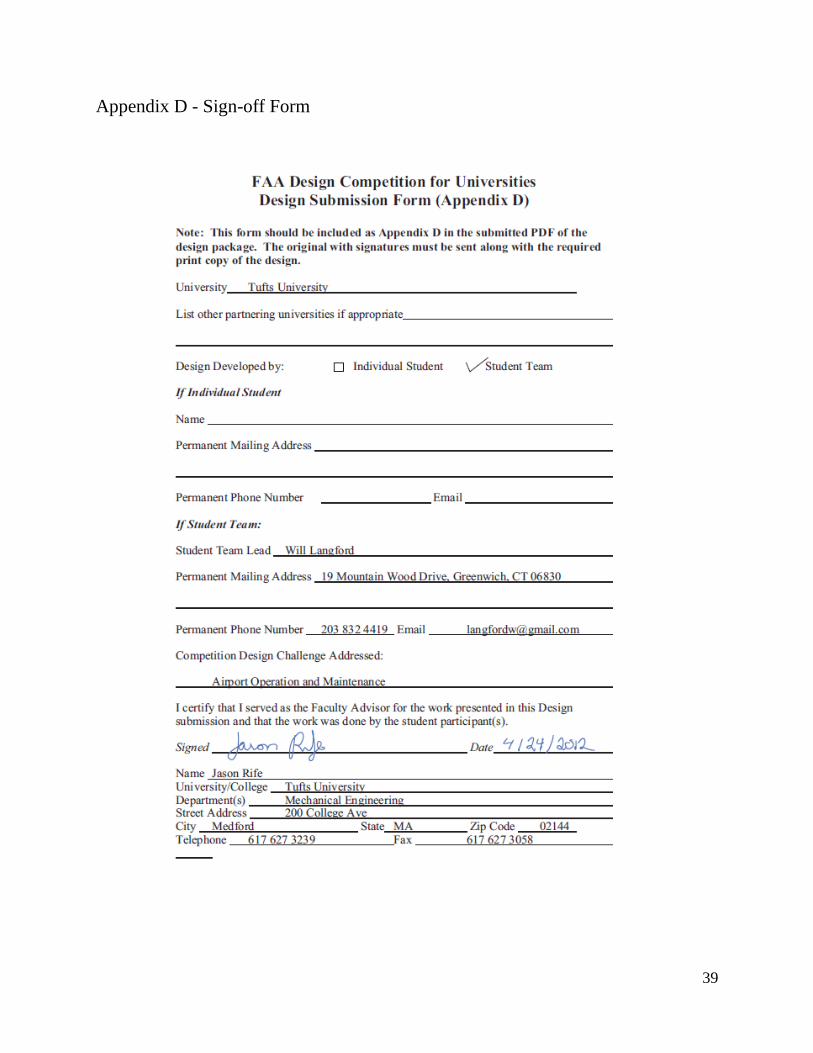
Appendix D - Sign-off Form
Page 50
43
Appendix E - Evaluation of Educational Experience
1. Did the FAA Design Competition provide a meaningful learning experience for you? Why or
why not?
The FAA Design Competition for Universities provided a great educational experience for all of
us. As we will elaborate on below, we each gained invaluable experience in brainstorming and
working on a team, trying to find solutions to a real world issue, fabricating prototypes and
dealing with both the design phase and the debugging phase, and the opportunity to present our
ideas in a professional venue (both orally and on paper).
2. What challenges did you and/or your team encounter in undertaking the Competition? How
did you overcome them?
In addition to the challenges inherent in any engineering design process, we faced several key
challenges in this project that stand out.
One major challenge was the lag time between the start of the project and our first meeting
with Robert Lynch and Flavio Leo at Massport, which didn’t occur until November 10th,
roughly 2 months into the semester. We luckily had access to Professor Hannon’s knowledge of
the field, as well as numerous FAA Advisory Circulars, which both proved incredibly useful in
our initial phases of defining the problem, sketching preliminary specifications, and starting to
conceptualize our solution. Due to these resources we were able to have a solid understanding of
the problem and a good amount of progress towards our solution by the time we were able to
meet with Massport.
This contributed to another major challenge, which was the short time period we had to
manufacture our first prototype. By making extensive use of SolidWorks, especially motion
studies, we were able to isolate potential issues prior to fabrication and select the appropriate
Page 51
44
parts. We also were lucky to have help from Jim Hoffman, the manager of the Department of
Mechanical Engineering’s machine shop, while we were cutting, drilling, milling, and lathing the
various parts and materials that went into our prototype.
A major issue in the second semester was our lack of funding, as our Senior Design
capstone course was only during the fall semester. We had originally hoped to build a more
involved second prototype, incorporating both the navigation and the removal subsystems in a
larger, more robust package. We applied for funding from the School of Engineering and weren’t
awarded a grant until late in the semester, at which point it was too late to spend the money. We
refocused our efforts instead on building a small but robust robot from the parts we had on hand
so we could develop the necessary navigation algorithms and continue exploring other aspects of
our system.
3. Describe the process you or your team used for developing your hypothesis.
After our initial conversation with Professor Hannon, an industry expert, about the various issues
that airport operators are concerned about, we discussed which ones interested us and ways we
might solve them. After considering which problems lined up well with our capabilities, we
decided to focus on FOD detection and removal.
4. Was participation by industry in the project appropriate, meaningful and useful? Why or why
not?
It was very helpful to talk to industry professionals to hear recommendations and concerns with
what went well and what to improve. No book or research paper could compare to the feedback
from professionals in the field that work with FOD issues on a daily basis. We were able to use
our first meeting to create specifications for our prototype, and at our second meeting we were
able to actually test our prototype on the Boston Logan International Airport runway. Getting
Page 52
45
customer feedback is an important part of any engineering design process, so getting the
opportunity to meet with actual airport experts, which we likely wouldn’t have had otherwise,
was a great experience.
5. What did you learn? Did this project help you with skills and knowledge you need to be
successful for entry in the workforce or to pursue further study? Why or why not?
This project helped us learn some skills while strengthening others. We were challenged to solve
physical problems during the design and manufacturing process and we worked to overcome
software issues during programming and debugging phases of our project as well during the
presentation of our findings.
During the design and fabrication process of FODHippo, there were many times where we were
reminded how crucial it was to keep a comprehensive and detailed record of what we had done
and what needed to be done. From selecting the parts and materials we were using, to choosing
connection types and sizes, and eventually to the assembly process, we gained a great deal of
respect for how many decisions and seemingly insignificant tasks go into the design process.
We were afforded an opportunity to apply many of the skills we’d been taught in our other
classes, from electronics to mechanical design to coding, in a real project. Along with learning to
apply our skills, we picked up some more along the way, such as how much thought needs to go
into the process for selecting parts and how to effectively debug a system combining hardware
and software.
This project taught us that a mechanical design can only be successful if all of the necessary
software aspects function properly, and that one successful test run does not qualify a prototype
as a success. It was necessary to do extensive debugging and testing before presenting our
design, and we made sure that we were prepared. We learned how important communication and
Page 53
46
distribution of tasks were in order to create an efficient group environment. We gained
experience with organizing our ideas into succinct presentations to not only focus our material,
but also to strengthen our ability to convey information in a concise manner.
For all of these reasons, this project helped us establish the skills and knowledge we need
both to pursue further study and to eventually launch successful careers.
Faculty Evaluation (G. Leisk and J. Rife)
l. Describe the value of the educational experience for your student(s) participating in this
Competition submission.
In the capstone design experience in the Mechanical Engineering Department at Tufts
University, the goal is to expose students to open-ended design challenges with real-world
applications. The competition complements the student educational experience in a number of
ways.
The FAA Competition presents relevant, challenging, real-world problems that provide a rich
design space for student innovation.
The recognition and awards associated with the competition provide added motivation for
students to go beyond course requirements to outshine other competitors.
The ability to visit with operators and see the design environment is an invaluable experience
for the students. In the case of our team, students learned an enormous amount about airport
operations from their discussions with Massport representatives and from the opportunity
Massport provided to the students to field their robotic system on an inactive runway at
Logan airport.
Page 54
47
The competition’s emphasis on system engineering further complements the student learning
experience. In our mechanical engineering program, we generally emphasize product design,
with projects producing a tangible, working prototype. In order to field an entry for the FAA
competition, students had to go one step farther, considering a whole-system analysis
involving many interacting components, safety issues, training, maintenance, etc.
2. Was the learning experience appropriate to the course level or context in which the
competition was undertaken?
The students undertook this competition effort as their Senior capstone project in Mechanical
Engineering. A subset of the students extended their efforts through subsequent independent
studies, for credit.
The challenging project the students focused on had all of the key educational elements that
capstone experiences should present: open-ended design challenge (no off-the-shelf solutions
exist), customer-oriented problem, required knowledge from various disciplinary areas of
Mechanical Engineering, and necessitated good organizational skills and use of design tools. The
student team thrived on the project and were awarded the Department’s James O’Leary Design
Award (awarded each year to a Senior undergrad team that has excelled in a design effort).
3. What challenges did the students face and overcome?
The students faced two key challenges. The first challenge was to schedule an initial visit to
Logan Airport and meet with relevant operators to gather detailed information on the design
challenge they were tackling. It took some time to coordinate a visit; however, the team utilized
the delay to conduct background research and to start developing preliminary ideas for solving
the stated problem. When a trip to Logan Airport took place, the operators were extraordinarily
helpful in discussing operational issues and showing the team and mentors the runways and other
Page 55
48
aspects of the design environment. The students were able to share their initial ideas and get
immediate feedback. The second challenge involved a live demonstration of an early working
prototype. In a follow-up visit to Logan Airport, live testing of the prototype highlighted a few
design issues that only became apparent in the actual design environment. This valuable
experience helped to direct the team to make several design improvements.
4. Would you use this Competition as an educational vehicle in the future? Why or why not?
The FAA Design Competition will be a perennial source for capstone design experiences at Tufts
University. The educational value, real-world design challenges, and competition format are all
motivational elements.
5. Are there changes to the Competition that you would suggest for future years?
The FAA Design Competition for Universities is typically announced close to Labor Day, which
is at the beginning of the Fall semester for most universities. One of the important initial design
activities is to visit airport operators and/or companies and experts to gather background
information on the problem(s) and existing solutions. The late announcement date of the
Competition makes it difficult on instructors to pre-plan to organize student team(s) and to
initiate the aforementioned initial design activity in a timely manner. Ideal timing of the
announcement would be in late Spring or early Summer.
Page 56
49
Appendix F - References
[1] Insight SRI, "The Economic Cost of FOD to Airlines," London, 2008.
[2] BEA, "Accident on 25 July 2000".
[3] XSight, [Online]. Available: http://www.xsightsys.com. [Accessed 18 December 2011].
[4] E. E. H. e. al., "Performance Assessment of a Mobile Radar Based Foreign Object Debris
Detection System," Washington, 2011.
[5] Aerosweep, [Online]. Available: http://aerosweep.com/fodboss/. [Accessed 26 October
2011].
[6] Federal Aviation Administration, "Airport Foreign Object Debris Detection Equipment,"
Washington, 2004.
[7] Federal Aviation Administration, "Airport Foreign Object Debris Management,"
Washington, 2004.
[8] Federal Aviation Administration, "Chapter 3: Principles of System Safety," in FAA System
Safety Handbook, Washington, DC, 2000.
[9] Federal Aviation Administration, "Airport Safety Self-Inspection," Washington, 2004.
[10] R. Thrapp, C. Westbrook and D. Subramanian, "Robust Localization Algorithms for an
Autonomous Campus Tour Guide," in IEEE International Conference on Robotics and
Automation, 2001.
[11] K. Ohno, T. Tsubouchi, B. Shigematsu, S. Maeyama and S. Yuta, "Outdoor Navigation of a
Mobile Robot Between Buildings Based on DGPS and Odometry Data Fusion," in IEEE
International Conference on Robotics and Automation, 2003.
[12] M. Saini, "Get Ready for ADS-B," Washington, 2010.
[13] F. Leo, Personal Interview, 2011.
[14] R. J. Lynch, Personal Interview, 2011.
[15] D. Hannon, Personal Interview, 2011.
[16] Massport, 2012. [Online]. Available: http://www.massport.com/logan-airport/about-
logan/Pages/Default.aspx. [Accessed 15 April 2012].
Page 57
50
Appendix G - FODHippo in Action
Page 58
51
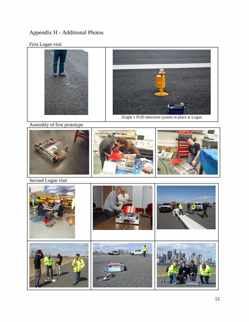
Appendix H - Additional Photos
First Logan visit
Xsight’s FOD detection system in place at Logan
Assembly of first prototype
Second Logan visit
Page 59
52
Appendix I - Links to Videos
First Prototype
http://youtu.be/JALfnCEsUK4
GPS Navigation
http://youtu.be/yql4bbO7Dg4
Second Logan Trip
http://youtu.be/V-WQPh7PRK0
Page 60
53
Appendix J - Detailed Drawings (not to scale)
Page 63
56
Appendix K - Parts for First Prototype
Part Supplier Part Number Quantity Total
Price Martin Flat-Free Rubber Wheels RobotMarketplace ZP61RT-325 2 $23.98
Dual VNH2SP30 Motor Driver Pololu 708 1 $59.95
19:1 Metal Gearmotor w/ Encoder Pololu 1442 2 $79.90
37D Metal Gearmotor Bracket Pair Pololu 1084 1 $7.95
Needle Roller Brng for 3/8" Shaft McMaster-Carr 1434K25 2 $16.46
Acme Round Nut 3/8"-5 Sz McMaster-Carr 95075A101 2 $62.44
Precision Acme Threaded Rod 3/8"-5 McMaster-Carr 99030A100 1 $34.62
Surface Hinge W/Holes Removable Pin McMaster-Carr 1586A12 2 $11.56
Round Head Machine Screw 1/2"-13
(10 pack)
McMaster-Carr 90276A712 1 $5.16
Ball Bearing for Shaft Diameter 3/8" McMaster-Carr 7208K51 2 $42.36
Socket Set Screw 6-32 Thread (pack) McMaster-Carr 92313A144 1 $2.78
Acetal Resin Rod 3/4" Diameter McMaster-Carr 8576K18 5 ft. $14.75
Aluminum (Alloy 6061) 1-3/8" x 1' McMaster-Carr 8974K171 1 $11.63
Acrylic Sheet .236" Thick, 12" X 24", McMaster-Carr 85635K533 3 $52.89
10-32 Round Head Phillips Machine
Screw (100 pack)
McMaster-Carr 90272A829 2 $8.44
10-32 Hex Nut (100 pack) McMaster-Carr 90545A111 2 $4.56
Aluminum (Alloy 6063) 90 Deg Angle,
1/8" X 4" X 4", 8' L
McMaster-Carr 88805K67 $65.10
Stud-Mount Ball Transfer Std, 5/8"
Steel Ball
McMaster-Carr 6460K21 2 $13.34
Threaded Rod M8 Size, 1 Meter
Length, 1.25 mm Pitch
McMaster-Carr 99055A125 $4.29
Aluminum (Alloy 6061) U-Channel,
3"X 1-1/2", 3' L
McMaster-Carr 1630T311 1 $24.23
Aluminum (Alloy 6061) 1/8" Thick X
4" Width X 6' Length
McMaster-Carr 8975K16 1 $30.83
Aluminum (Alloy 6061) 1" Square, 1'
Length
McMaster-Carr 9008K141 1 $11.99
Clear Cast Acrylic Sheet .125" Thick,
12" X 24"
McMaster-Carr 8560K257 2 $29.66
28 Teeth Timing Pulley 3/8" bore SDP-SI A 6Z53-
028DF0912
2 $12.16
28 Teeth timing pulley 6mm bore SDP-SI A
6Z53M028DF0906
3 $18.24
350 Teeth, 9mm (.354) Wide Belt SDP-SI A 6R53M350090 1 $16.42
Pitsco DC Drive Motor Tetrix W39083 1 $29.95
HiTec HS-485HB Standard Servo Tetrix HS-485HB 1 $14.95
Sparkfun Ardumoto Sparkfun DEV-09815 1 $24.95
Wixel Arduino Shield + Wixel Pair +
USB Cable
Pololu 2501 1 $49.95
Arduino Uno Pololu 1616 1 $29.95
Subtotal: $815.44
Page 64
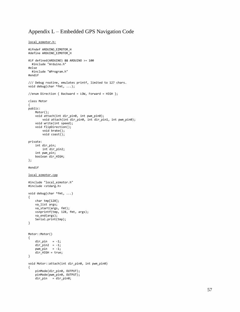
57
Appendix L – Embedded GPS Navigation Code
local_ezmotor.h: #ifndef ARDUINO_EZMOTOR_H #define ARDUINO_EZMOTOR_H #if defined(ARDUINO) && ARDUINO >= 100 #include "Arduino.h" #else #include "WProgram.h" #endif /// Debug routine, emulates printf, limited to 127 chars. void debug(char *fmt, ...); //enum Direction { Backward = LOW, Forward = HIGH }; class Motor { public: Motor(); void attach(int dir_pin0, int pwm_pin0); void attach(int dir_pin0, int dir_pin1, int pwm_pin0); void write(int speed); void flipDirection(); void brake(); void coast(); private: int dir_pin; int dir_pin2; int pwm_pin; boolean dir_HIGH; }; #endif local_ezmotor.cpp #include "local_ezmotor.h" #include <stdarg.h> void debug(char *fmt, ...) { char tmp[128]; va_list args; va_start(args, fmt); vsnprintf(tmp, 128, fmt, args); va_end(args); Serial.print(tmp); } Motor::Motor() { dir_pin = -1; dir_pin2 = -1; pwm_pin = -1; dir_HIGH = true; } void Motor::attach(int dir_pin0, int pwm_pin0) { pinMode(dir_pin0, OUTPUT); pinMode(pwm_pin0, OUTPUT); dir_pin = dir_pin0;
Page 65
58
pwm_pin = pwm_pin0; } void Motor::attach(int dir_pin0, int dir_pin1, int pwm_pin0) { pinMode(dir_pin0, OUTPUT); pinMode(dir_pin1, OUTPUT); pinMode(pwm_pin0, OUTPUT); dir_pin = dir_pin0; dir_pin2 = dir_pin1; pwm_pin = pwm_pin0; } void Motor::write(int speed) { speed = constrain(speed,-255,255); if (speed < 0) { if (dir_HIGH) { digitalWrite(dir_pin, HIGH); if (dir_pin2 != -1) digitalWrite(dir_pin2, LOW); } else { digitalWrite(dir_pin, LOW); if (dir_pin2 != -1) digitalWrite(dir_pin2, HIGH); } analogWrite(pwm_pin, -speed); } else { if (dir_HIGH) { digitalWrite(dir_pin, LOW); if (dir_pin2 != -1) digitalWrite(dir_pin2, HIGH); } else { digitalWrite(dir_pin, HIGH); if (dir_pin2 != -1) digitalWrite(dir_pin2, LOW); } analogWrite(pwm_pin, speed); } } void Motor::flipDirection() { dir_HIGH = !(dir_HIGH); } void Motor::brake() { if (dir_pin2 != -1) { digitalWrite(dir_pin, HIGH); digitalWrite(dir_pin2, HIGH); } else { return; //"Error: Brake functionality not available for single direction input"; } } void Motor::coast() { analogWrite(pwm_pin, 0); } local_DifferentialDrive.h #ifndef DifferentialDrive_H #define DifferentialDrive_H #if defined(ARDUINO) && ARDUINO >= 100 #include "Arduino.h" #else #include "WProgram.h" #endif #include "local_ezmotor.h"
Page 66
59
class DifferentialDrive { public: DifferentialDrive(); void attachMotor(int dir1, int dir2, int pwm); void set_desired_heading(float h); void set_desired_velocity(int v); void update_motors(); void set_current_heading(float h); void set_current_velocity(int v); float get_current_heading(); float k_heading; float k_velocity; Motor left_motor, right_motor; private: int num_motors_attached; float current_heading; float desired_heading; int current_velocity; int desired_velocity; int pwm_limit; int base_pwm; int left_pwm; int right_pwm; }; #endif local_DifferentialDrive.cpp //#include "ezmotor.h" #include "local_DifferentialDrive.h" #include <stdarg.h> DifferentialDrive::DifferentialDrive() { num_motors_attached = 0; current_heading = -1; desired_heading = -1; current_velocity = -1; desired_velocity = -1; pwm_limit = 255; base_pwm = 50; left_pwm = 0; right_pwm = 0; k_heading = 0.0; k_velocity = 0.0; } void DifferentialDrive::attachMotor(int dir_pin0, int dir_pin1, int pwm_pin0) { if (num_motors_attached == 0) { // attach motor 1 (left motor) left_motor.attach(dir_pin0, dir_pin1, pwm_pin0); num_motors_attached++; } else if (num_motors_attached == 1) { // attach motor 2 (right motor) right_motor.attach(dir_pin0, dir_pin1, pwm_pin0); } else { //ERROR: You can only attach two motors to a differential drive robot. } } void DifferentialDrive::set_desired_heading(float h) {
Page 67
60
desired_heading = h; // (in degrees with 90 = straight ahead) } void DifferentialDrive::set_desired_velocity(int v) { desired_velocity = v; } void DifferentialDrive::set_current_heading(float h) { current_heading = h; // (in degrees with 90 = straight ahead) } void DifferentialDrive::set_current_velocity(int v) { current_velocity = v; } float DifferentialDrive::get_current_heading() { return current_heading; } void DifferentialDrive::update_motors() { // CONTROL LAWS GO HERE // e.g. ... float dTheta; // float dTheta = desired_heading - current_heading; // (in degrees) float diff1 = current_heading - desired_heading; float diff2 = current_heading - (360 - desired_heading); Serial.print(diff1); Serial.print(" "); Serial.print(diff2); Serial.print(" "); if (abs(diff1) <= abs(diff2)) { dTheta = -diff1; } else { dTheta = diff2; } int dV = desired_velocity - current_velocity; // (in cm/s) //base_pwm += k_velocity*dV; base_pwm = 220; // left_pwm += k_velocity*dV; // right_pwm += k_velocity*dV; /// *************** <----- DON'T FORGET TO UNCOMMENT // left_pwm = 100; // right_pwm = 100; left_pwm = base_pwm + int(k_heading*dTheta); // signs may need to be flipped right_pwm = base_pwm - int(k_heading*dTheta); base_pwm = constrain(base_pwm, 100, 200); left_pwm = constrain(left_pwm, 100, 255); right_pwm = constrain(right_pwm, 100, 255); Serial.print("DV: "); Serial.print(desired_velocity); Serial.print(" CV: "); Serial.print(current_velocity); Serial.print(" dV: "); Serial.print(dV); Serial.print(" CH: "); Serial.print(current_heading); Serial.print(" dTheta: "); Serial.print(dTheta); Serial.print(" LPWM: "); Serial.print(left_pwm); Serial.print(" RPWM: ");
Page 68
61
Serial.println(right_pwm); left_motor.write(left_pwm); right_motor.write(right_pwm); } fod_bot.pde #include <TinyGPS.h> #include "local_DifferentialDrive.h" #include <NewSoftSerial.h> DifferentialDrive fody; // heading gain, velocity gain TinyGPS gps; NewSoftSerial nss(11, A2); const int enc1A = 2, enc1B = 12, enc2A = 3, enc2B = 13; long left_odom, right_odom; float TICKS_PER_CM = 21.145, TICKS_PER_DEGREE = 15.478; struct waypoint { float x; float y; }; float lat, lon, heading, velocity; unsigned long age; boolean newdata; waypoint gps_waypoints[20]; int num_waypoints; float last_heading; float desired_heading; int desired_velocity; void setup() { Serial.begin(115200); nss.begin(4800); // attach motors fody.attachMotor(4,5,9); // M1 fody.attachMotor(8,7,10); // M2 // set gains fody.k_heading = 1.0; fody.k_velocity = 1.0; // attach encoders attachInterrupt(0, read_quad_right, CHANGE); attachInterrupt(1, read_quad_left, CHANGE); // interrupt 1 conflicts with dir_1a initialize_waypoints(); add_waypoint(42.40352, -71.11911); // 4 on track //add_waypoint(42.40602, -71.11690); //anderson hallway add_waypoint(42.40313, -71.11809); //add_waypoint(42.40334, -71.11775); //add_waypoint(42.40360, -71.11753); // fody.add_waypoint(x, y); // fody.add_waypoint(x, y); // fody.add_waypoint(x, y); // fody.add_waypoint(x, y); fody.left_motor.write(150); fody.right_motor.write(150); delay(3000); }
Page 69
62
// ******* MAIN LOOP ********* void loop() { newdata = false; unsigned long start = millis(); // Every 5 seconds we print an update //while (millis() - start < 1000) //{ if (feedgps()){ newdata = true; } //} update_waypoint(); //fody.set_desired_heading(0); //fody.set_desired_velocity(0); update_current_state(); fody.update_motors(); /// *************** <------ DON'T FORGET TO UNCOMMENT THIS! } void update_current_state() { if (newdata) { // zero encoders gps.f_get_position(&lat,&lon,&age); fody.set_current_velocity(int(gps.f_speed_mps()*100)); //[cm/s] //fody.set_current_velocity(100); //TAKE THIS OUT //Serial.println(" ARE WE HERE?"); if (int(gps.f_speed_mps()*100) > 10) { left_odom = 0; right_odom = 0; fody.set_current_heading(gps.f_course()); //[degrees] last_heading = gps.f_course(); } Serial.print("lat: "); Serial.print(lat); Serial.print(" lon: "); Serial.print(lon); print_float(lat, TinyGPS::GPS_INVALID_F_ANGLE, 9, 5); print_float(lon, TinyGPS::GPS_INVALID_F_ANGLE, 10, 5); Serial.print(" vel: "); Serial.print(int(gps.f_speed_mps()*100),DEC); Serial.print(" course: "); Serial.println(gps.f_course()); } //else { float h = last_heading + ((float)(left_odom - right_odom))/(float)TICKS_PER_DEGREE; h += 720; int num_fit = h/360; h = h - num_fit*360; fody.set_current_heading(h); // } // calculate desired heading desired_heading = gps.course_to(lat,lon,gps_waypoints[0].x,gps_waypoints[0].y); Serial.print("DH: "); Serial.print(desired_heading); fody.set_desired_heading(desired_heading); } void update_waypoint() { if (gps_waypoints[0].x == 0 && gps_waypoints[0].y == 0) { Serial.println("Messed up"); // we've reached the end of the waypoint queue... STOP desired_velocity = 0;
Page 70
63
//fody.k_velocity = 0; //fody.k_heading = 0; // stop the program ? // add new waypoints ? } else { desired_velocity = 60; //[cm/s] //int dist = (int)pow(pow(gps_waypoints[0].x - lat,2) + pow(gps_waypoints[0].y - lon,2),0.5); int dist = gps.distance_between(gps_waypoints[0].x,gps_waypoints[0].y,lat,lon)*100; //[cm] //Serial.println(dist); if (abs(dist) < 500) { // distance from waypoint to consider that we're there (16ft ~= 500cm) Serial.println("Removing Waypoint."); remove_waypoint(); } } fody.set_desired_velocity(desired_velocity); } void initialize_waypoints() { for (int i = 0; i < (sizeof(gps_waypoints)/sizeof(waypoint)); i++) { gps_waypoints[i] = (waypoint){0, 0}; } } void add_waypoint(float x, float y) { gps_waypoints[num_waypoints] = (waypoint){x, y}; num_waypoints++; } void remove_waypoint() { for (int i = 0; i < (sizeof(gps_waypoints)/sizeof(waypoint))-1; i++) { gps_waypoints[i].x = gps_waypoints[i+1].x; gps_waypoints[i].y = gps_waypoints[i+1].y; } num_waypoints--; } void read_quad_left() { if (digitalRead(enc2A) != digitalRead(enc2B)) { left_odom++; } else { left_odom--; } } void read_quad_right() { if (digitalRead(enc1A) == digitalRead(enc1B)) { right_odom++; } else { right_odom--; } } boolean feedgps() { while (nss.available()) { if (gps.encode(nss.read())) return true; } return false; } static void print_float(float val, float invalid, int len, int prec) { char sz[32];
Page 71
64
if (val == invalid) { strcpy(sz, "*******"); sz[len] = 0; if (len > 0) sz[len-1] = ' '; for (int i=7; i<len; ++i) sz[i] = ' '; Serial.print(sz); } else { Serial.print(val, prec); int vi = abs((int)val); int flen = prec + (val < 0.0 ? 2 : 1); flen += vi >= 1000 ? 4 : vi >= 100 ? 3 : vi >= 10 ? 2 : 1; for (int i=flen; i<len; ++i) Serial.print(" "); } feedgps(); }