FAA Pavement Design: AC 150/5320-6E – FAARFIELD 2009 PCC Workshop Indiana Chapter – American Concrete Pavement Association January 27, 2009 Gary L. Mitchell, P.E. Director of Airports and Pavement Technology American Concrete Pavement Association
Transcript
FAA Pavement Design: AC 150/5320-6E – FAARFIELD
2009 PCC WorkshopIndiana Chapter – American
Concrete Pavement AssociationJanuary 27, 2009
Gary L. Mitchell, P.E.Director of Airports and Pavement Technology
American Concrete Pavement Association
FAA Pavement Design
AC 150/5320-6E, Airport Pavement Design and Evaluation
– Completely revised in 2008– New design methodologies for Rigid and Flexible
pavements– Software dependent design procedures– Addresses modern airplane parameters
Chapter 2Soil Investigations and
Evaluation
Chapter 2 Soil Investigations and Evaluation
Very few significant changesStill uses Unified Soil Classification (USC) system
Reference to ASTM 2487
0
10
20
30
40
50
60
0 10 20 30 40 50 60 70 80 90 100 110
LIQUID LIMIT (LL)
PLA
STIC
ITY
IND
EX (P
I)
CL - ML ML - OH
MH - OH
GW CLGP MLGM OLGC CHSW MHSP OHSM PTSC
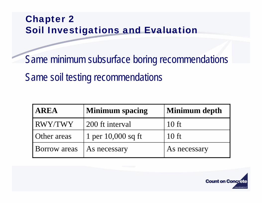
Chapter 2 Soil Investigations and Evaluation
Same minimum subsurface boring recommendationsSame soil testing recommendations
AREA Minimum spacing Minimum depth
RWY/TWY 200 ft interval 10 ftOther areas 1 per 10,000 sq ft 10 ftBorrow areas As necessary As necessary
Chapter 2 Soil Investigations and Evaluation
Continues to split soil compaction requirements based upon 60,000 lb gross weight airplane
< 60,000 ASTM D 698 Standard Proctor> 60,000 ASTM D 1557 Modified Proctor
Chapter 2 Soil Investigations and Evaluation
Soil Strength Parameter for RIGID pavementResilient Modulus E (psi) or Modulus of Subgrade Reaction – k-value (pci)
Design value – “conservative selection”K-value can be estimated from CBR
7788.0
26CBR1500
⎥⎦⎤
⎢⎣⎡ ×
=k (k in pci)
Chapter 2 Soil Investigations and Evaluation
Modulus of Subgrade Reaction – k-value (pci)• Removed the statement:
“Rigid pavement is not too sensitive to k-value and an error in estimating k will not have a large impact on rigid pavement thickness”
Design comparisons show that FAAFIELD thickness design is more sensitive to k-value (converted to E) than the previous Westergaard-based procedure.
1012141618202224
0 50 100 150 200 250 300 350 400k-value
PC
C th
ickn
ess
(in)
Chapter 2 Soil Investigations and Evaluation
Soil Strength Parameter for RIGID pavementk-value (pci)
With the 3D finite element design procedurethe sensitivity of k-value to rigid design is increased. Errors in selection of k-value can generate noticeable changes in the required pavement thickness.
K = 150PCC = 17.38
K = 200PCC = 16.14
Example not indicative of all situations
Chapter 2 Soil Investigations and Evaluation
Seasonal FrostSame Frost Groups (FG-1, FG-2, FG-3 & FG-4)
Determination of Depth of Frost PenetrationBased on local Engineering experiencei.e. local construction practice, building codes, etc.No nomographs or programs provided
Chapter 3Pavement Design
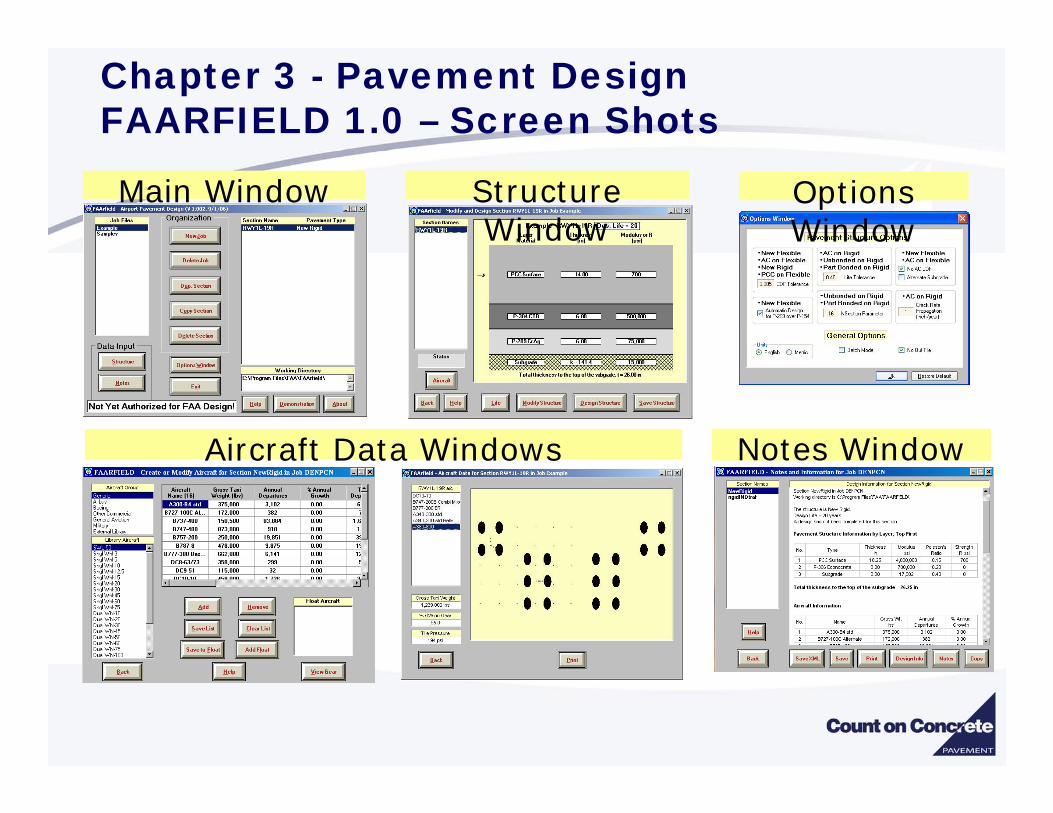
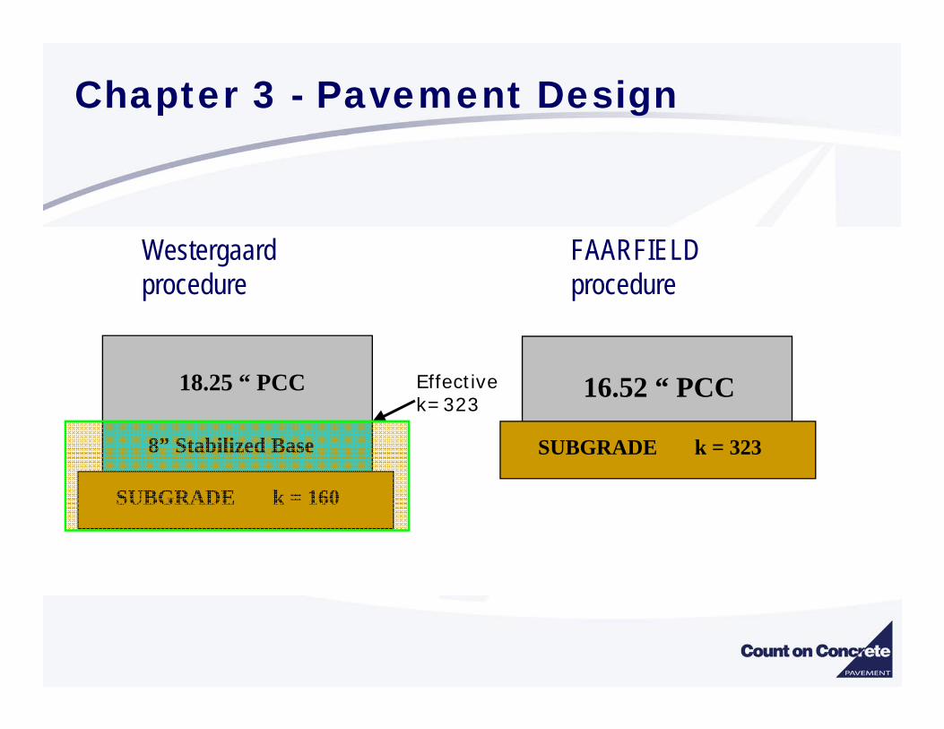
Chapter 3 - Pavement Design
Completely New ChapterCovers standard pavement design procedures for both flexible and rigid pavementApplies to pavement designed for airplanes with gross weights exceeding 30,000 lbsDesign procedure requires the use of computer program, i.e. FAARFIELD
Rigid Pavement Design based on 3-Dimensional Finite Element model
Westergaard design procedure no longer used.
Flexible Pavement Design based on Layered Elastic design procedure
US Corp of Engineers CBR Method no longer used
Chapter 3 - Pavement Design
Traffic ModelsNew procedures require that ALL anticipated traffic be included in the traffic model.Concept of “design aircraft” is no longer usedCumulative Damage Factor (CDF) replaces need for design aircraft procedure.
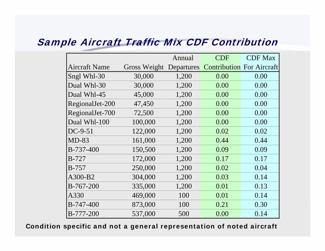
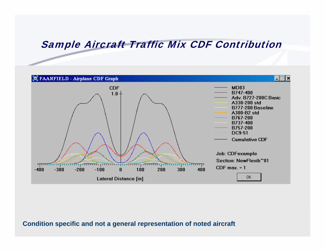
Chapter 3 - Pavement Design
Traffic Model - Cumulative Damage FactorSums Damage From Each Aircraft
Based upon its unique pavement loading characteristics and Location of the main gear from centerline
DOES NOT use the “design aircraft” method of condensing all aircraft into one design model
Chapter 3 - Pavement Design
Traffic Model - Cumulative Damage FactorSums Damage From Each Aircraft - Not From “Design Aircraft”
Must use the entire traffic mixtureNo more “Design Aircraft”Comparisons between new and previous design procedures using “design aircraft” for the traffic model will result in significant errors
Chapter 3 - Pavement Design
Chapter 3 - Pavement Design
Traffic Model – Airplane CharacteristicsFAARFIELD program currently provides 198 different aircraft modelsEach model is unique with respect to gross load, load distribution, wheel spacing, and tire pressureGear types identified in accordance with FAA Order 5300.7
Eliminates “widebody” terminology
Chapter 3 - Pavement Design
# X #/ # X #
Main Gear Designation Body/Belly Gear Designation
# of gear types in tandem
Gear type, e.g. S, D, T, or Q
# of main gears in line onone side of the aircraft Gear type, e.g. S, D, T, or Q
# of gear types in tandem
Total # of body/belly gears
(Assumes gear is present on both sides. The value indicates number of gears on one side. A value of 1 is omitted for simplicity.)
(Because body/belly gear may not be symmetrical, the gear must identify the total number of gears present and a value of 1 is notomitted if only one gear exists.)
(A value of 1 is omitted for simplicity.)
(A value of 1 is omitted for simplicity.)
Traffic Model – Gear Naming Convention
Chapter 3 - Pavement Design
Single
SDual
DTriple
TQuadruple
Q
Traffic Model – Gear Naming Convention
Chapter 3 - Pavement Design
SingleS
2 Singles in Tandem2S
3 Singles in Tandem3S
DualD
2 Duals in Tandem2D
3 Duals in Tandem3D
TripleT
2 Triples in Tandem2T
3 Triples in Tandem3T
QuadrupleQ
2 Quadruples in Tandem2Q
3 Quadruples in Tandem3Q
Traffic Model – Gear Naming Convention
Chapter 3 - Pavement Design --Examples
SSingle Wheel
DDual Wheel
2DDual Tandem
2D/2D1A340-600
3DB777
2D/D1DC-10
Chapter 3 - Pavement Design --Examples
2D/2D2B747
2D/3D2A380
C5Lockheed C5
Chapter 3 - Pavement Design
Traffic Model – Pass to Coverage (P/C) RatioLateral movement is known as airplane wander and is model by statistically normal distribution.
Standard Deviation = 30.435 inches (773 mm)(P/C) -The ratio of the number of trips (or passes) along the pavement for a specific point on the pavement to receive one full-load application.-6E utilizes new procedure for determining P/C
Chapter 3 - Pavement Design
Traffic Model – Pass to Coverage (P/C) RatioRigid PavementOne Coverage = One full stress application to the bottom of
the PCC layer
– Flexible PavementOne Coverage = One repetition of maximum strain at the top
of the subgrade layer
Chapter 3 - Pavement Design
Traffic Model – Pass to Coverage (P/C) Ratio-6E (FAARFIELD) uses the concept of “Effective Tire Width”Rigid Pavement – Effective width is defined at the surface of the pavement (equal to tire contact patch)(same as previous P/C procedures)
Flexible Pavement – Effective width is defined at the surface of the subgrade layer
Chapter 3 - Pavement Design
Traffic Model – Pass to Coverage (P/C) RatioFlexible pavement P/C ratio varies with depth of
pavementPavement Surface
Top of Subgrade
Chapter 3 - Pavement Design – Frost Design
FROST DESIGN - 3 optionsComplete Frost Protection
Remove frost susceptible materials to below frost depthLimited Frost Protection
Remove frost-susceptible material to 65% frost depthLimits frost heave to tolerable level
Reduced Subgrade StrengthReduce subgrade support value Design adequate load carrying capacity for weakened condition
Chapter 3 - Pavement Design – Typical Sections
Airport pavements are generally constructed in uniform, full width sections
Variable sections are permitted on runway pavementsDesigner should consider:
Practical feasibility – complex construction operationsEconomical feasibility – cost of complex construction
Chapter 3 - Pavement Design – Typical Sections
Variable sections permitted on runway pavements
Full pavement thickness
Outer edge thickness (based on 1% of normal traffic)
Pavement thickness tapers to outer edge thickness
Transitions
Design using arrival traffic only
Chapter 3 - Pavement Design – Typical Sections
Variable sections permitted on runway pavements1. Minimum 12” up to 36”
2. For runways wider than 150’, this dimension will increase.
3. Width of tapers and transitions on rigid pavements must be an even multiple of slabs, minimum one slab width.
Full pavement thickness
Outer edge thickness (1% traffic)
Pavement thickness tapers
to outer edge thickness
12
3
12
RIGID PAVEMENT DESIGN
AC 150/5320-6E, Airport Pavement Design and Evaluation
CHAPTER 3, Section 3 – Rigid Pavement Design
Chapter 3 Section 3 – Rigid Pavement Design
Typical Rigid Pavement
Portland Cement Concrete (PCC)
Subbase Course **
Subgrade
** Stabilization required when airplanes exceeding 100,000 lbs are in the traffic mixture.
Chapter 3 Section 3 – Rigid Pavement Design Observed Cracking –Airbus PEP test
Chapter 3 Section 3 – Rigid Pavement Design
Critical for Bottom-Up Crack
Critical for Top-Down Crack
Possible Critical Load Locations- Considering Slab Curling
Chapter 3 Section 3 – Rigid Pavement Design
Pavement Structural Design Life
• Default “design life” is for 20 years
• Structural design life indicates pavement performance in terms of allowable load repetitions before SCI = 80.
• Structural life is determined based upon annual departures multiplied by 20 (yrs). This value may or may not correlate with calendar years depending upon actual pavement use.
• Pavement performance in terms of surface condition and other distresses which might affect the use of the pavement by airplanes is not directly reflected in the structural design life.
Chapter 3 Section 3 Rigid Failure Model as Implemented in FAARFIELD
where:a = 0.5878, b = 0.2523, c = 0.7409, d = 0.2465,C = coveragesSCI = Structural Condition IndexFs’ = is a compensation factor that accounts for a high-stiffness (stabilized) base.Fc= calibration factor = 1.13Note: Equation is linear in log (C) for any value of This is a departure from LEDFAA rigid failure model.
sF ′
( )
( )
( ) ⎥⎥⎥⎥
⎦
⎤
⎢⎢⎢⎢
⎣
⎡
′+−⎟⎠⎞
⎜⎝⎛ −
′+−⎟⎠⎞
⎜⎝⎛ −
+×
⎥⎥⎥⎥
⎦
⎤
⎢⎢⎢⎢
⎣
⎡
′+−⎟⎠⎞
⎜⎝⎛ −
′=
bFbdSCI
bcFbcadSCI
CbFbdSCI
bdFFDF
s
s
s
s
c
1001
1001
log
1001
Rigid pavement failure model in FAARFIELD
Chapter 3 Section 3 – Rigid Pavement Design
Initial cracking occurs at the same time for aggregate and stabilized subbase
Stabilized section performs better (longer life) after initial cracking
00
20
40
60
80
100
Log Coverages (n)
Stru
ctur
al C
ondi
tion
Inde
x (S
CI) STBS
AGBS
CONCRETE STRUCTURAL MODELFAARFIELD
Rigid pavement failure model in FAARFIELD
Rigid Failure Model as Implemented in FAARFIELD
is the calibration, or scaling, factor. It is not derived from analysis of full-scale data, but rather from comparison of the uncalibrated failure model with corresponding designs based on the design chart method in AC 150/5320-6D. In FAARFIELD 1.1, has a value of 1.13.
cF
cF
( )
( )
( ) ⎥⎥⎥⎥
⎦
⎤
⎢⎢⎢⎢
⎣
⎡
′+−⎟⎠⎞
⎜⎝⎛ −
′+−⎟⎠⎞
⎜⎝⎛ −
+×
⎥⎥⎥⎥
⎦
⎤
⎢⎢⎢⎢
⎣
⎡
′+−⎟⎠⎞
⎜⎝⎛ −
′=
bFbdSCI
bcFbcadSCI
CbFbdSCI
bdFFDF
s
s
s
s
c
1001
1001
log
1001
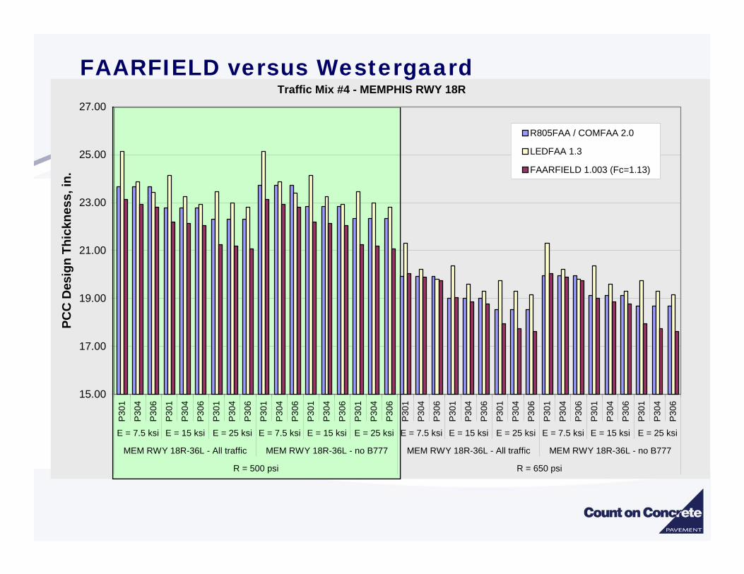
Traffic Mix #4 - MEMPHIS RWY 18R
15.00
17.00
19.00
21.00
23.00
25.00
27.00P
301
P30
4
P30
6
P30
1
P30
4
P30
6
P30
1
P30
4
P30
6
P30
1
P30
4
P30
6
P30
1
P30
4
P30
6
P30
1
P30
4
P30
6
P30
1
P30
4
P30
6
P30
1
P30
4
P30
6
P30
1
P30
4
P30
6
P30
1
P30
4
P30
6
P30
1
P30
4
P30
6
P30
1
P30
4
P30
6
E = 7.5 ksi E = 15 ksi E = 25 ksi E = 7.5 ksi E = 15 ksi E = 25 ksi E = 7.5 ksi E = 15 ksi E = 25 ksi E = 7.5 ksi E = 15 ksi E = 25 ksi
MEM RWY 18R-36L - All traffic MEM RWY 18R-36L - no B777 MEM RWY 18R-36L - All traffic MEM RWY 18R-36L - no B777
FAARFIELD accepts Resilient Modulus ESG or k-value(only necessary to enter one value)
• Converts k-value to modulus
ESG = Resilient modulus of subgrade, in psik = Foundation modulus of the subgrade, in pciAASHTO T 222, Nonrepetitive Static Plate Load Test of Soils and Flexible Pavement Components, for Use in Evaluation and Design of Airport and Highway Pavements
284.126kESG =
Chapter 3 Section 3 – Rigid Pavement Design
Subgrade Characteristicsk-value can be estimated from CBR value
k = Foundation modulus of the subgrade, in pci
Allowable range of k-value in FAARFIELD – 17.2 to 361.1
7788.0
261500
⎥⎦⎤
⎢⎣⎡ ×
=CBRk
Chapter 3 Section 3 – Rigid Pavement Design
Subbase Layer CharacteristicsMinimum material requirements
Up to three subbase layers allowed in FAARFIELD (minimum of one required)
Chapter 3 Section 3 – Rigid Pavement Design
Subbase Layer CharacteristicsStabilization required with airplanes exceed 100,000 lbsAggregate materials - modulus dependent on thickness
Modulus calculated by FAARFIELD based on thickness4 inch minimum thickness requirement
Chapter 3 Section 3 – Rigid Pavement Design
Portland Cement Concrete Layer CharacteristicsMinimum material requirements
P-501Flexural Strength as design variable
FAA recommends 600 – 700 psi for design purposesFAARFIELD will allow 500 – 800 psiASTM C 78 Flexural Strength of Concrete (Using Simple Beam with Third-Point Loading)Modulus fixed at 4,000,000 psi
6 Inch minimum thickness requirementThickness rounded to the nearest 0.5 inch
Chapter 3 Section 3 – Rigid Pavement Design
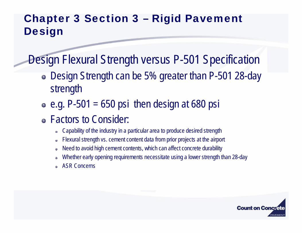
Design Flexural Strength versus P-501 SpecificationDesign Strength can be 5% greater than P-501 28-day strengthe.g. P-501 = 650 psi then design at 680 psiFactors to Consider:
Capability of the industry in a particular area to produce desired strengthFlexural strength vs. cement content data from prior projects at the airportNeed to avoid high cement contents, which can affect concrete durabilityWhether early opening requirements necessitate using a lower strength than 28-dayASR Concerns
Chapter 3 Section 3 – Rigid Pavement Design
Traffic Input for Rigid Pavement DesignAirplane characteristics
198 Airplane models currently available in FAARFIELDWheel load – determined automatically based on gross weightWheel locations – Internal to FAARFIELD aircraft libraryTire pressure – Internal to FAARFIELD aircraft library
Frequency of load applicationEntered as annual departures
Arrival traffic ignoredUser determines percent of total airport volume
•FAARFIELD either places the gear perpendicular or parallel to the edge of a slab.
•FAARFIELD makes this determination.
FAArfield – Gear Alignment on slab edge
Chapter 3 Section 3 – Rigid Pavement Design
3-D Finite Element Model
Chapter 3 Section 3 – Rigid Pavement Design
Key Advantages of 3-D ModelCorrectly models rigid pavement features - slab edges and joints.Provides the complete stress and displacement fields for the analyzed domain.Handles complex load configurations easily.No inherent limitation on number of structural layers or material types.Not limited to linear elastic analysis.
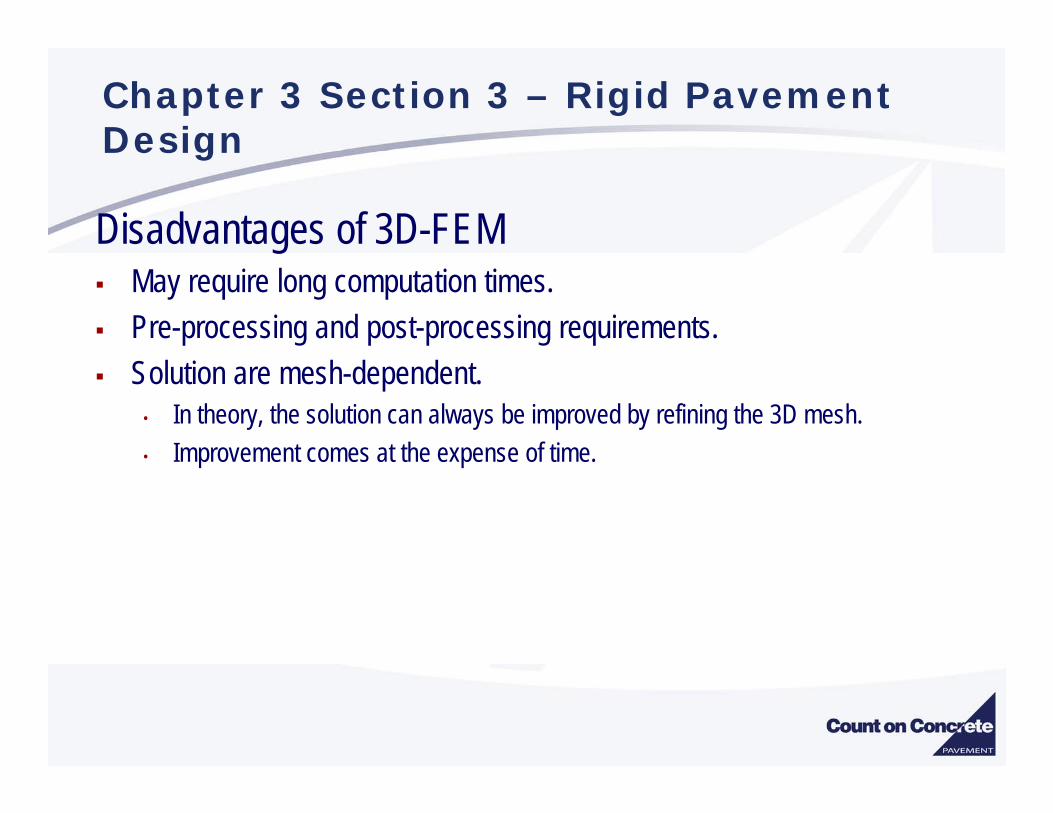
Disadvantages of 3D-FEM May require long computation times.Pre-processing and post-processing requirements.Solution are mesh-dependent.
• In theory, the solution can always be improved by refining the 3D mesh.• Improvement comes at the expense of time.
Chapter 3 Section 3 – Rigid Pavement Design
3D Finite Element is:A method of structural analysis.Applicable to a wide range of physical structures,
boundary and loading conditions.3D Finite Element is not:
A design method or procedure.An exact mathematical solution.Always preferable to other analysis models.
Chapter 3 Section 3 – Rigid Pavement Design
Structures and ModelsIn finite element analysis, it is important to distinguish:
The physical structure
The idealized model
The discretized (approximate) model
Chapter 3 Section 3 – Rigid Pavement Design
Improvement in Solution Time
Approximate time for B-777 stress solution:• July 2000: 4 - 5 hours• July 2001: 30 minutes
(single slab with infinite element foundation)• May 2002: 2 - 3 minutes
(implement new incompatible modes elements)• Current version implemented in FAARFIELD:
10 seconds or less
Chapter 3 Section 3 – Rigid Pavement Design
Chapter 3 Section 3 – Rigid Pavement Design
Rigid Pavement Joint Types and Details
Chapter 3 Section 3 – Rigid Pavement Design
Rigid Pavement Joint Types and Details5 joint types provided in 5320-6E
Isolation JointsType A – Thickened EdgeType A-1 Reinforced Isolation Joint
Contraction JointsType B – HingedType C – DoweledType D – Dummy
Construction JointsType E – Doweled
Chapter 3 Section 3 – Rigid Pavement Design
Rigid Pavement Joint Types and DetailsIsolation Joints
Beveled Joint DetailIntended to reduce chipping and spalling attributed to snow plows
Chapter 3 Section 3 – Rigid Pavement DesignRigid Pavement Joint Types and Details• Dowel Bar Spacing at Slab Corner
Chapter 5 –Pavements For Light Aircraft
Rigid Pavement – Joint Steel For Rigid PavementDowels
TABLE 3-17. DIMENSIONS AND SPACING OF STEEL DOWELS
Thickness of Slab Diameter Length Spacing
6-7 in (152-178 mm) ¾ in1 (20 mm) 18 in (460 mm) 12 in (305 mm)
7.5-12 in (191-305 mm) 1 in1 (25 mm) 19 in (480 mm) 12 in (305 mm)
12.5-16 in (318-406 mm) 1 ¼ in1 (30 mm) 20 in (510 mm) 15 in (380 mm)
16.5-20 in (419-58 mm) 1 ½ in1 (40 mm) 20 in (510 mm) 18 in (460 m)
20.5-24 in (521-610 mm) 2 in1 (50 mm) 24 in (610 mm) 18 in (460 mm)1Dowels noted may be solid bar or high-strength pipe. High-strength pipe dowels must be plugged on each end with a tight-fitting plastic cap or mortar mix.
Chapter 5 –Pavements For Light Aircraft
Rigid Pavement – Joint Steel For Heavy Duty Pavement
All Tie Bars5/8 inch Deformed Bars (16 mm)
30 inch long (76 mm)
30 inch center (76 mm)
• Notes:1. Transverse and longitudinal joint spacing.2. For typical runway and taxiway geometries, the corresponding longitudinal joint spacing is 18.75 ft. (5.7 m).3. Joint spacings shown in this table are maximum values that may be acceptable under ideal conditions.4. Smaller joint spacings should be used if indicated by past experience 5. Pavements subject to extreme seasonal temperature differentials or extreme temperature differentials during
PCC over existing flexible pavement (whitetopping)PCC bonded to existing PCCPCC unbonded to existing PCC
Deleted partially bonded PCC
FlexibleHot Mix Asphalt over existing flexible pavementHot Mix Asphalt over existing rigid pavement
Chapter 4 – Airport Pavement Overlays.
Overlay design requires the FAARFIELD programInput variables include:
Existing pavement structureIncluding material properties and traffic requirements
Existing pavement conditionRigid – use Structural Condition Index (SCI)Flexible – requires engineering judgment
Chapter 4 – Airport Pavement Overlays.
Structural Condition Index (SCI)Derived from the Pavement Condition Index as determined by ASTM D 5340 Airport Pavement Condition Index Surveys SCI is computed using only structural components from the PCI survey (6 of 15 distress types)
SCI will always be greater than or equal to the PCI
Chapter 4 – Airport Pavement Overlays.
Structural Condition Index (SCI)SCI = 80 – FAA definition of structural failure
50% of slabs with structural crack
Pavement with an SCI = 80 and no durability issues can appear to be in surprisingly good condition. Pavement with SCI > 80 but with durability issues can look severely failed.
Chapter 4 – Airport Pavement Overlays.
Structural Condition Index (SCI)TABLE 4-1. RIGID PAVEMENT DISTRESS TYPES USED TO CALCULATE THE STRUCTURAL CONDITION INDEX, (SCI)
Cumulative Damage Factor Used (CDFU)SCI = 100 when there is no visible distress contributing to reduction in SCI ( no structural distress types)Condition of existing pavement described by CDFU
Chapter 4 – Airport Pavement Overlays.
Cumulative Damage Factor Used (CDFU)
00
20
40
60
80
100
L o g C o ve ra g e s (n )
Stru
ctur
al C
ondi
tion
Inde
x (S
CI) ST BS
AG BS
SCI = 100
80<SCI<100100 % CDFU
LOG SCALE – COVERAGES
No load related distresses (cracks)
CDFU < 100
Str
uct
ura
l C
on
dit
ion
In
dex
(SC
I)
Chapter 4 – Airport Pavement Overlays.
Cumulative Damage Factor Used (CDFU)CDFU defines amount of structural life used
For structures with aggregate base
LU = number of years of operation of the existing pavement until overlayLD = design life of the existing pavement in years
FAARFIELD modifies this relationship for stabilized subbase to reflect improved performance
Chapter 4 – Airport Pavement Overlays.
Overlay on Rubblized Concrete PavementDesign process is similar to New PCCRubblized PCC layer is available in FAARFIELD