52
Jim H. Burge College of Optical Sciences + Steward Observatory University of Arizona Tucson, AZ 85721 Fabrication and testing of large free-form surfaces

Jim H. Burge
College of Optical Sciences + Steward Observatory
University of Arizona
Tucson, AZ 85721
Fabrication and testing of
large free-form surfaces

Introduction
• A tutorial on Fabrication and testing of large freeform
aspheres?
• A tutorial should teach you how to do something –
not really appropriate for this topic.
• Instead, I’ll give a talk that provides:
– Summary of the problem
– Outline the basic steps for fabrication, emphasizing
commercial systems
– Extreme aspheres at University of Arizona
• I restrict the talk to
– Large optics > 1 m
– Optics with surface requirements <

Freeform surfaces
• General aspheres
• Lack rotational symmetryFor small parts, the parent is made, then the desired off axis piece is
cut out. Not interesting here.
• When used in optical systems, these have the same
tight figure requirements as other optics
• Difficulties come from aspheric departure
– Shaping (grinding and polishing)
– Measuring
– Aligning
• Complexity comes from lack of symmetry

Applications for large freeform aspheres
Imaging systems with unobscured pupil
• New Solar Telescope at Big Bear Solar Observatory
• Unobscured optical design for thermal reasons
– 1.6-m aperture, taken from 5.3-m f/0.7 parent Gregorian design
– Primary mirror is steep 1.7-m diameter off-axis parabola

Applications for large freeform aspheres
Mirror segments for large axisymmetric systems
• Giant Magellan Telescope
• Thirty Meter Telescope
• James Webb Space Telescope
GMT
8.4-m PM segments
1.1-m SM segments TMT
1.4-m PM segments
JWST
1.3-m PM segments

Applications for freeform aspheresCorrection optics for wide field systems
Three-mirror anastigmat uses axisymmetric Cassegrain-type primary-secondary combination, slightly off axis
Tertiary mirror is fully off axis
Other TMA designs are fully off axis
Designs often start with off axis portion of axisymmetric parent, then are allowed to depart

Initial shaping for “standard” optics
Sphere
Special geometry for sphere
Blanchard generator allows very rapid
shaping with large wheel
Axisymmetric asphere
Part rotates about axis.
Generator head follows a single profile
NC control of z vs r
Diamond grinding to get the shape close
(to within 5 – 50 µm)

Lapping for “standard” optics
Lapping with loose abrasives or polishing compound
Sphere
Use large rigid tools. Symmetry of
sphere insures that tools fit.
Natural smoothing does most of the work
Axisymmetric asphere
Most work is on “zones” in the surface by
rotating the part under the polisher
Smaller and smaller tools are used

Measurement of “standard” optics
Sphere
Use interferometer
Interferometer
with axisymmetric null
corrector
Subaperture interferometry
for small optics
Annular subapertures
Zygo Verifire AsphereOff axis
subapertures
QED SSI
Axisymmetric aspheres
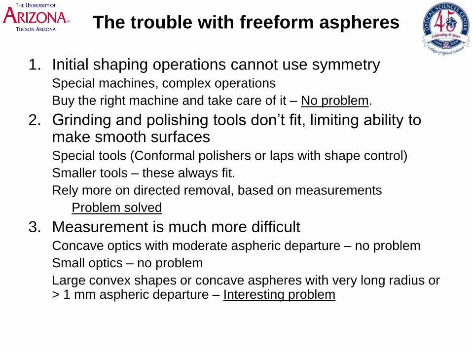
The trouble with freeform aspheres
1. Initial shaping operations cannot use symmetrySpecial machines, complex operations
Buy the right machine and take care of it – No problem.
2. Grinding and polishing tools don’t fit, limiting ability to make smooth surfacesSpecial tools (Conformal polishers or laps with shape control)
Smaller tools – these always fit.
Rely more on directed removal, based on measurements
Problem solved
3. Measurement is much more difficultConcave optics with moderate aspheric departure – no problem
Small optics – no problem
Large convex shapes or concave aspheres with very long radius or > 1 mm aspheric departure – Interesting problem

Initial shaping of freeform aspheres
Requires 3-axis coordinated motion
always at a loss of accuracy
increased complexity increases risk of mistake
Tool servo
direction (r )
“Fast tool servo”
for diamond turning
Replace diamond by
grinding spindle
GMT used radial motion
to cut contours
5-axis machining center
Multiple suppliers of
machines that can achieve
~ 10 um tolerances
Accuracy depends on how
much “love” the machine gets

Lapping (grinding and polishing)
• Small-tool computer controlled surfacing using 5-axis
machine, proprietary laps, polishers, algorithms
– L3, ITT, Goodrich, UA
• Large tool for large optics
– Stressed lap at University of Arizona
• Commercial systems capable of > 1-m
– Zeeko: “Precessions”
– QED Technologies: Magneto-Rheological Finishing

Small tool computer controlled polishing
Small tools always fit the aspherical surface
Well calibrated removal allows excellent results
Tends to be very slow for large optics

Small tool computer controlled polishing
1. Measure surface error
2. Run polisher over surface, spending more time on high
spots.
Limitations of small tool computer controlled polishing
• Measurement error
• Predictability of material wear
– Material removal rate
– Tool influence function shape
• Response of polishing tool used
– Large tool cannot fix small scale errors
– Small tool takes too long, imperfections introduce some small
scale errors
• Edges are always challenging
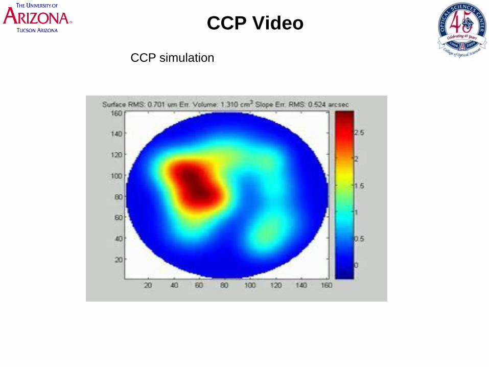
CCP Video
CCP simulation
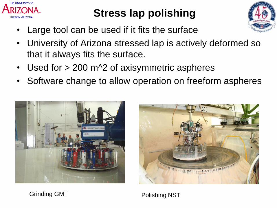
Stress lap polishing
• Large tool can be used if it fits the surface
• University of Arizona stressed lap is actively deformed so
that it always fits the surface.
• Used for > 200 m^2 of axisymmetric aspheres
• Software change to allow operation on freeform aspheres
Grinding GMT Polishing NST

Performance of stressed lap
• NST primary was initially shaped with 5-axis NC machining
• Surface was ground polished with stressed lap, guided by only
coarse metrology
• The first interferogram showed 630 nm rms irregularity, no high
slopes,
• This mirror has 1400 µm aspheric departure!
First interferogram (Egg shaped pupil from
distortion in null corrector)
First surface map After correction of distortion

Computer controlled polishing in Arizona
UA Swingarm computer
controlled polisher
Mounting OAP onto CCP
CCP in operation

UA polisher
Video: UA CCP.MOV

Zeeko “Precessions”
• Uses inflated bonnet with
polishing cloth
• 5-axis NC control
Video: Zeeko.mpg
Video: Bonnet…

• Video : Zeeko ellipsoid polish

Zeeko IRP1200 (1.2-m)
Zeeko is developing IRP2400

MRF from QED Technologies
Material removal via shear motion of
special fluid
5-axis CNC to control removal on optical
surface
Video: MRF animation

• Video: Q22-950…


Polishing Technologies
• Multiple solutions exist
• All have demonstrated excellent performance
• Efficiency depends on
– Volume removal rates
– Reliability of polishing influence function
– Use of natural smoothing
• Accuracy depends mostly on the measurements

Measurements of freeform aspheres
• Coordinate measuring machines: can measure anything
• Interferometry
– No commercial solutions for general 1-m class parts
– Concave parts with modest aspheric departure can be measured
with null correctors (computer generated holograms)
• Developments at University of Arizona
– Metrology for GMT segments
• The challenge of a lifetime
– Metrology developed for large convex off axis aspheres
• Applicable for wide class of aspheres

Coordinate measuring machines
• Measures any shape
• Accuracy of ~ 1 µm is typical
• Limited by data point density,
measurement time
Leitz Infinity
measuring volume of 1200 x 1000 x
700mm
Accuracy 0.3 µm + 1 µm/m

Interferometry + CGH null correctors
• Computer generated holograms use diffraction to modify spherical wavefront from interferometer into a shape that matches the asphere – no symmetry required
• CGHs fabricated using writing technology for IC reticles
• Alignment features are incorporated into the CGH
• Limitations:
– Center of curvature must be accessible• Concave surfaces with < 30 m ROC
– Amount of aspheric correction limited to ~2000 waves.
Interferometer
Spherical wavefront
aspherical
wavefront
CGH
Aspheric surface to
be measured

Extreme freeform aspheres at UA
Testing challenges and solutions for two extreme aspheres
• Giant Magellan Telescope primary mirror segment
– 8.4-m diameter
– 14.5 mm aspheric departure
– 36 m radius of curvature
• Off axis convex aspheres
– Off axis parabolic surfaces
– Convex, 1.4-m in diameter
– 300 um aspheric departure

The Giant Magellan Telescope
25-m aplanatic Gregorian
Primary mirror
f/0.7 near-paraboloid
Made from 8.4-m segments
Secondary mirror
Ellipsoid
segmented like primary
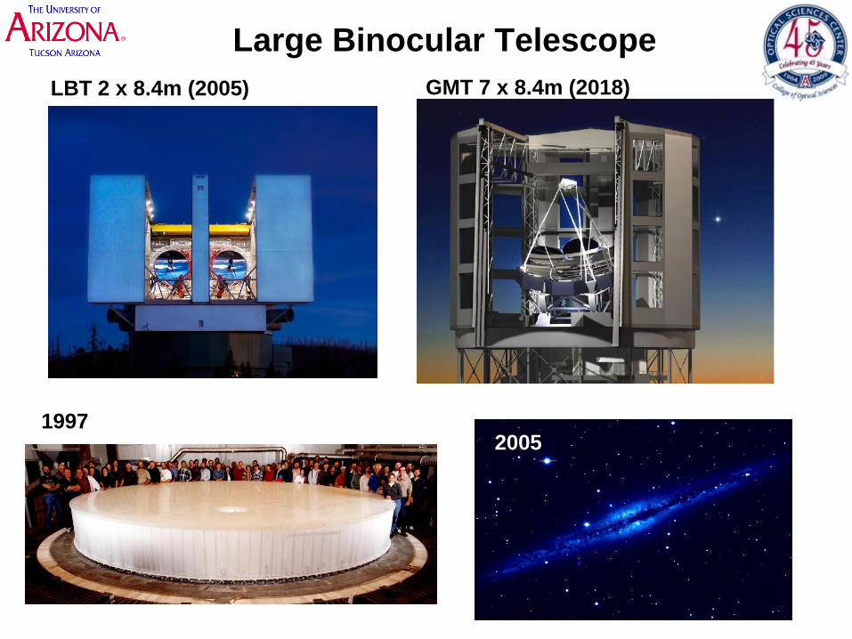
Large Binocular Telescope
19972005
LBT 2 x 8.4m (2005) GMT 7 x 8.4m (2018)

Optical testing of GMT segments
Heritage (LBT) GMT
Axisymmetric
Test optics at ~20 meters
Light from optical test is only 200
mm diameter near the test optics –
allows direct measurement of test
system
No Axisymmetry
Light path defined by GMT is much
larger(~3.5 meters across at the top of our tower)
Test
optics
~1.4 mm aspheric departure ~14 mm aspheric departure
Test wavefront
defined to match
aspheric shape
of mirror
20 m

Interferometric testing for GMT
GMT segment
Spherical mirror3.75 m diameter
ROC: 25 m
Tilt: 14.2º
Tested in situ from floor
M20.75 m diameter
ROC: 1.26 m
CGH130 mm diameter
Line spacing > 15 μm
Interferometer
23 m
Sam

GMT testing : wavefront correction
Interferometer provides in situ
measurement of 3.8-m mirror 26
meters away

GMT optical test

Making the 3.75 m fold sphere
Polished at the Mirror Lab
Cast in the Mirror Lab
spinning oven
Coated at Kitt Peak

Support of 3.75-m fold sphere
Hangs from “Active” support, allowing quasi-static
force adjustment based on in situ measurement
3750 mm
mm455
mmmm

Scanning pentaprism test
Scanning pentaprism measures slope errors
by producing collimated beams parallel to
parent axis. Displacement of focused spot is
measured with camera in focal plane.
Pentaprism rail lies in plane
perpendicular to parent axis.
Hub rotates rail to scan
different diameters.
Scanning pentaprism test as implemented
for GMT off-axis segments. Pentaprism
rail is suspended from tower.A
xis
of p
are
nt p
ara
bolo
id
parent paraboloid
Off-axis mirror
Collimated laser
CCD camera at
focus of paraboloid
Fixed reference
pentaprism
with beamsplitter
Scanning
pentaprism
Image at CCD
Axis
of p
are
nt p
ara
bolo
id
parent paraboloid
Off-axis mirror
Collimated laser
CCD camera at
focus of paraboloid
Fixed reference
pentaprism
with beamsplitter
Scanning
pentaprism
Image at CCD

Pentaprism test of 1.7 m off-axis NST mirror
• 1/5 scale GMT pentaprism test
• This was done in late 2007 before the mirror was finished.
• The pentaprism test only samples lowest order aberrations
• The PP results agree with results from interferometry to a few nm
pentaprism measurementinterferometric test
nm
surface

sphere-mounted retro-
reflector for laser tracker
Retroreflector for interferometer
and position sensing detector (PSD)
assemblies in 4 places at edge of
mirror
laser tracker & distance-measuring
interferometers (DMI)
PSD 10% BS
DMI retroreflector
DMI laser and remote
receivers
laser tracker
DMIs
Laser Tracker Plus
Accuracy of < 0.5 um demonstrated

GMT status, early October 2009
Surface is polished specular
~2.4 um rms irregularity
Optical test system works, but is not
yet calibrated
Expect 6 months of polishing, fussing
with the test

Extreme freeform aspheres II
1.4-m convex off-axis aspheres
~300 µm aspheric departure
• Solid Zerodur substrates
• Surface measurements
– In situ measurements with Swingarm Optical CMM
– Mechanical measurement of curvature
– Measurements with Fizeau interferometry

Swingarm Optical CMM
• Uses optical displacement probe
• Continuous arc scans create profiles
• Profiles stitched together to give surface maps
• In situ measurements on polishing machine
probe and alignment stages
convex asphere
center of curvature
optical axis
axis of rotation
probe trajectory
rotary stage
arm

SOC performance
Errors with odd symmetry : 0.023 µm rms
Errors with even symmetry : 0.025 µm rms
Ca
libra
ted m
ea
su
rem
en
t e
rro
r in
µm
Normalized position on mirror
Repeatable errors calibrated
to ~5 nm rms/scan
Average of 8 scans, < 2 nm rms repeatability
-50 -40 -30 -20 -10 0 10 20-0.02
-0.015
-0.01
-0.005
0
0.005
0.01
0.015
0.02rms=6nm
Encoder angle in degrees
Surface
measurement
in µm
Surface
measurement
in µm
Repeatability ~ 6 nm rms/scan
Position in mm

Surface maps from SOC data
Pattern of 64 scans Interpolated data : 75 nm rmsGrid map rms=0.07471um
100 200 300 400
50
100
150
200
250
300
350
400
-0.1
0
0.1
0.2
0.3
Grid map power removed rms=0.07245um
100 200 300 400
50
100
150
200
250
300
350
400
-0.1
0
0.1
0.2
0.3
0.4
Grid map power astigmatism and coma removed rms=0.031665um
100 200 300 400
50
100
150
200
250
300
350
400
-0.1
-0.05
0
0.05
0.1
0.15
4 terms removed, rms=0.07857um
50 100 150 200
20
40
60
80
100
120
140
160
180
200 -0.2
-0.1
0
0.1
0.2
0.3
0.4
896 term reconstruction : 78 nm rms 43 terms removed, rms=0.0065192um
50 100 150 200
20
40
60
80
100
120
140
160
180
200
-0.04
-0.02
0
0.02
0.04
0.06
Low order terms removed : 6 nm rms

Power (ROC measurement)
using spherometer
• 3-ball spherometer ~0.1 micron resolution
• Geometry carefully controlled, measure sag to < 0.3 µm

OAP
Collimator
Measurement
CGH
Lens
CCD camera
Aperture
Reference wavefront
Zero order from CGH
Reflects from reference sphere
Test wavefront
First order from CGH
Reflects from OAP
Return : common path
Both wavefronts coincide
The difference between these gives
the shape error in the OAP
Common
CGH
Aspheric surface
m = 1
m = 0
m = 0 from OAP
m = 1 from sphere
Blocked by aperture:
Reference and test wavefronts come to
focus and pass through aperture
All other orders and reflections are blocked
Reference
sphere
Spherical surface
f/15 diverger
objective
diffuser
Fizeau test using a spherical
reference, corrected by imaging a CGH
Common path
Phase shift interferometry
3 nm rms accuracy

UA achieved very low noise measurements with
CGH Fizeau system
Excellent fringe visibility
Excellent spatial resolution
Low measurement noise

Comparison of Fizeau, SOC
• The Fizeau test was budgeted as < 3.3 nm rms uncertainty, after correction
for low order terms.
• SOC measurements of the OAPs are consistent with this.Fizeau SOC
Raw data
After
removing low
order terms
Difference109 nm rms 117 nm rms
14 nm rms 16 nm rms 7 nm rms
Largest errors in Fizeau came from
coating defect on large fold flat 1 nm rms
ghost fringes 1 nm rms
Astigmatism and coma from
alignment were not needed to be
controlled accurately

Conclusion
• Free-form aspheres are here to stay
• Mature methods and equipment are available for
shaping and finishing large free-form optics.
• The interferometric measurement can be the most
difficult (and costly) aspect of manufacturing
• The UA Swingarm Optical CMM has demonstrated
excellent performance. This shows real promise of
providing a general metrology solution.
• I thank Zeeko, QED, UA for help with this talk


