Design Hydroqen - and Fabrication of a Detection Calibration System ~ September 8, 1967 ! Submitted to: George C, Marshall Space Flight Center Huntsville, Alabama 35812 Submitted by: /Aero Vas Corp- P, 0, Box 448 Troy, New York'J 12181 brought to you by CORE View metadata, citation and similar papers at core.ac.uk provided by NASA Technical Reports Server
Transcript
D e s i g n
H y d r o q e n
- and Fabr ica t ion of a D e t e c t i o n C a l i b r a t i o n
Sys tem ~
September 8 , 1967 !
Submi t t ed t o : G e o r g e C, Marshal l Space F l i g h t C e n t e r H u n t s v i l l e , A l a b a m a 35812
Submitted by: / A e r o V a s C o r p - P, 0, Box 448 Troy, New Y o r k ' J 1 2 1 8 1
https://ntrs.nasa.gov/search.jsp?R=19670031245 2020-03-16T16:43:32+00:00Zbrought to you by COREView metadata, citation and similar papers at core.ac.uk
D e t a i l R e s u l t s Sa fe ty Operat ing I n s t r u c t i o n s I n s t a l l a t i o n T e s t Resu l t s
Explosive T e s t and R e s u l t s
1
2 2
Appendix 5
6
A f f i d a v i t of T e s t
References
SCOPE OF WORK AND GENERAL RESULTS
Scope of Work
The scope of work included the design, fabrication, testing, delivery and installation of a Hydrogen Detection Calibration System which would meet or exceed all specifications set forth in the subject contract under A1 "Statement of Work".
Results of Contract Effort
Aero Vac Corp. delivered and installed at G.M.S.F.C,,
Huntsville, Alabama, during the period July 21 thru July 25, the equipment specified in the contract "Statement of Work" . Included in this report are pertinent results of the engineering study required to meet all the contract specifications.
-2 -
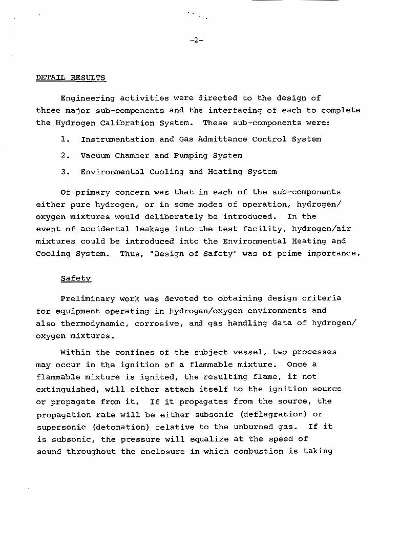
DETAIL RESULTS
Engineering a c t i v i t i e s were directed t o t h e design of t h r e e major sub-components and the i n t e r f a c i n g of each t o complete t h e Hydrogen C a l i b r a t i o n System. These sub-components w e r e :
1.
2.
Instrumentat ion and G a s Admittance Control System
Vacuum Chamber and Pumping System
3 . Environmental Cooling and Heating System
Of primary concern w a s t h a t i n each of t h e sub-components e i t h e r pure hydrogen, o r i n some modes of opera t ion , hydrogen/ oxygen mixtures would d e l i b e r a t e l y be introduced. I n t h e event of a c c i d e n t a l leakage i n t o t he t e s t f a c i l i t y , hydrogen/air mixtures could be introduced i n t o t h e Environmental Heating and Cooling System. Thus, "Design of Safe ty" w a s of prime importance.
Sa fe ty
Prel iminary work w a s devoted t o ob ta in ing design c r i t e r i a for equipment opera t ing i n hydrogen/oxygen environments and a l s o thermodynamic, co r ros ive , and gas handl ing data of hydrogen/ oxygen mixtures .
Within t h e confines of t h e subject v e s s e l , two processes may occur i n t h e i g n i t i o n of a flammable mixture. Once a flammable mixture is i g n i t e d , t h e r e s u l t i n g flame, i f not ext inguished, w i l l e i t h e r a t t a c h i t s e l f t o t h e i g n i t i o n source or propagate from it. I f it propagates from t h e source, t h e
propagation ra te w i l l be e i ther subsonic (de f l ag ra t ion ) o r supersonic (detonat ion) r e l a t i v e t o t h e unburned gas. I f it i s subsonic, t h e pressure w i l l equa l ize a t t h e speed of sound throughout t h e enclosure i n which combustion is t ak ing
-3 -
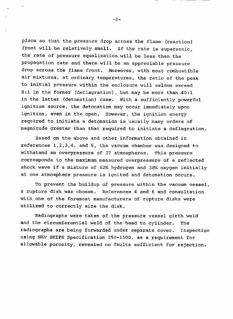
p l a c e so t h a t t h e p re s su re drop ac ross the flame ( r eac t ion ) f r o n t w i l l be r e l a t i v e l y s m a l l . I f t h e rate i s supersonic , t h e ra te of p re s su re e q u a l i z a t i o n w i l l be less than t h e propagat ion r a t e and there w i l l be an apprec i ab le p re s su re drop across t h e f l a m e f r o n t , Moreover, w i th m o s t combustible a i r mixtures , a t o rd ina ry temperatures , t h e r a t i o of the peak t o i n i t i a l p re s su re w i t h i n t h e enc losure w i l l seldom exceed 8 : l i n t h e former ( d e f l a g r a t i o n ) , b u t may be more than 40: l i n t h e l a t t e r (de tona t ion) case. W i t h a . s u f f i c i e n t l y powerful i g n i t i o n source , t h e de tona t ion may occur immediately upon i g n i t i o n , even i n t h e open. However, t he i g n i t i o n energy r e q u i r e d t o i n i t i a t e a de tona t ion i s u s u a l l y many o r d e r s of magnitude greater than t h a t r equ i r ed t o i n i t i a t e a d e f l a g r a t i o n .
Based on t h e above and other information obta ined i n r e f e r e n c e s 1 , 2 , 3 , 4 , and 5 , t he vacuum chamber w a s designed t o wi ths tand an overpressure of 37 atmospheres. T h i s p r e s s u r e corresponds t o t h e maximum measured overpressure of a r e f l e c t e d shock wave i f a mixture of 62% hydrogen and 38% oxygen i n i t i a l l y a t one atmosphere p r e s s u r e i s i g n i t e d and de tona t ion occurs .
To p reven t t h e bu i ldup of p re s su re w i t h i n t h e vacuum vessel, a r u p t u r e d i s k w a s chosen. References 4 and 6 and c o n s u l t a t i o n w i t h one of t h e foremost manufacturers of r u p t u r e d i s k s w e r e u t i l i z e d t o c o r r e c t l y s i z e t h e d isk .
Radiographs w e r e t aken of t h e p r e s s u r e v e s s e l g i r t h w e l d and t h e c i r c u m f e r e n t i a l weld of t h e head t o c y l i n d e r . rad iographs are be ing forwarded under s e p a r a t e cover. u s ing NAV SHIPS S p e c i f i c a t i o n 250-1500, as a requirement f o r a l lowable p o r o s i t y , revea led no f a u l t s s u f f i c i e n t for r e j e c t i o n .
The
Inspec t ion
-4-
d
The need t o prevent t h e overpressur iza t ion of the v e s s e l was d i c t a t e d by t h e allowable pressure i n the mechanical vacuum
pump. 200 p s i , it is repor ted t h a t t h e sha f t o i l s e a l s w i l l be damaged a t approximately 35 t o 40 p s i . Accordingly, t he b u r s t s p e c i f i c a t i o n s on t h e disk w e r e s e t a t 18-20 ps ig . I n order t o minimize the direct confronta t ion of the pump t o a de tona t ion wave, three (3) 90' bends w e r e used i n t h e vacuum piping.
W h i l e t h e r e s e r v o i r of t h e pump w i l l wi thstand approximately
The choice of vacuum pump f l u i d was based on t h e need f o r ox ida t ion r e s i s t a n c e , low flammabili ty and l u b r i c i t y . The choice of Cel lulube #220*, i n p a r t , w a s based on i t s being c e r t i f i e d (#194574 Bu Ships) as an approved f l u i d f o r A i r c r a f t C a r r i e r c a t a p u l t systems.
A l l motors a r e explosion proof: however, no manufacturer provides an explosion proof motor f o r opera t ion i n a hydrogen/ oxygen environment which conforms t o the app l i cab le code requi rements . Therefore , a source of gaseous n i t rogen is introduced i n t o t h e sealed electrical c o n t r o l box and thence purges the explosion proof motors by pass ing through t h e " l i q u i t i t e " condui t which d i s t r i b u t e s power conductors t o t h e
motors, h e a t e r s and t h e l i q u i d ni t rogen solenoid valve.
Hydrogen/oxygen mixtures have an Auto I g n i t i o n temperature of 400' C. I n order t o s t a y below t h i s temperature , the box conta in ing t h e e lectr ical h e a t e r e lements i n t h e Environmental Cooling and Heating System has a temperature s e n s i t i v e explosion proof s w i t c h set a t 500' F.
breakage, t h e loss of c i r c u l a t i n g a i r over t h e h e a t e r s w i l l r e s u l t i n a temperature rise causing the temperature d e t e c t o r s w i t c h t o disconnect power t o t h e h e a t e r e l emen t s .
I n t h e event of blower d r i v e be l t
"Cellulube i s a t r a d e name of t h e S t a u f f e r Chemical Company.
- 5-
Operatinq Instructions
See Appendix
Installation Test Results
The cognizant M.S.F .C, personnel witnessed the performance of the Environmental Heating and Cooling System through the full temperature excursion from -120' C to +77" @. Also, instruction was given to M.S.F,C, personnel in the proper calibration procedure for gas flowraters,and demonstrations of dynamic and static gas admittance procedures were exhibited.
-6 -
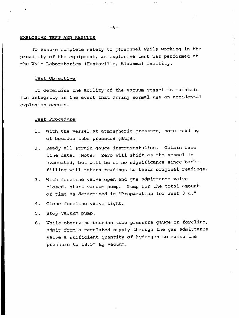
EXPLOSIVE TEST AND RESULTS
To a s s u r e complete s a f e t y t o personnel whi le working i n t h e proximity of t h e equipment, an explosive t e s t w a s performed a t t h e Wyle Labora to r i e s (Huntsv i l le , A l a b a m a ) f a c i l i t y .
T e s t Objec t ive
To determine t h e a b i l i t y of t h e vacuum v e s s e l t o main ta in i t s i n t e g r i t y i n t h e event t h a t during normal use an a c c i d e n t a l explos ion occurs ,
T e s t Procedure
1.
2 .
3.
4.
5.
6.
With t h e v e s s e l a t atmospheric p re s su re , no te reading of bourdon tube p res su re gauge.
Ready a l l s t r a i n gauge ins t rumenta t ion . Obtain base
l i n e d a t a . Note: Zero w i l l s h i f t as the v e s s e l i s evacuated, b u t w i l l be of no s i g n i f i c a n c e s i n c e back- f i l l i n g w i l l r e t u r n readings t o t h e i r o r i g i n a l readings.
With f o r e l i n e va lve open and gas admit tance va lve c losed , s t a r t vacuum pump. Pump f o r t h e t o t a l amount of t i m e as determined i n "P repa ra t ion f o r T e s t 3 d."
Close f o r e l i n e va lve t i g h t .
Stop vacuum pump.
While observing bourdon tube p res su re gauge on f o r e l i n e , admit from a r egu la t ed supply through t h e gas admittance va lve a s u f f i c i e n t q u a n t i t y o f hydrogen t o ra ise t h e p r e s s u r e t o 18.5" Hg vacuum.
CI - i -
7. Remove hydrogen s o u r ~ e from tes t a r e a ,
8. Again, w h i l e observing pressure gauge, admit from a regula ted supply through t h e gas admittance va lve a s u f f i c i e n t quan t i ty of oxygen t o r a i s e t he p res su re t o 0,O" Hg (in o t h e r words, one atmosphere] e Note: The mixture i n t he volume i s now 62% H2 by volume i n sxygen a t a t o t a l pressure of 0,O" Hgo
Close gas admittarice valve t i g h t , 9,
10, Remove oxygen source f m m t e s t a r e a ,
11. S t a r t recorders a rd "Pastax" camera,
1 2 . I g n i t e mixture ,
13 Provide Aero Vac with a l l records and f i l m from camera f o r eva lua t ion ,
Explosive T e s t Resu l t s
A s evidenced by t h e enclosed a f f i d a v i t , no defects o r o the r de t r imen ta l effects of t h e explosion could be found.
The 400 f o o t of f i l m , taken by Fas tax camera a t a r a t e of 6000 frames pe r second, is forwarded under sepa ra t e cover. Viewing of t h i s f i l m shows approximately 10 t o 1 2 frames of cond i t ions a t i n i t i a t i o n and during explosion, The f i l m shows t h e t es t success,
d
I
0 W Y L E JOB NO. 41129
C US TOMER P.O. NO. 13983
CONTRACT- MANUFACTURER -Aero -Vac
c n q x x a t i nn 1
L J
Aero-Vac Corporation P . 0 , Box 448 Troy, New York
Upon completion of t h e t e s t , t he chamber w a s v i s u a l l y inspected- There was no evidence of damage or permanent deformation detected during the above inspect ion except f o r the b u r s t d i s c tF-at rup- tured a s an t i c ipa t ed . I . ,
C U S T O M E R WITNESS
QAR D C A S
Q U A L I T Y CONTROL L
!
Page No. 2
i- m
2 2
I
I 1 1 1 1
REFERENCES
1.
2.
3 .
4.
5.
6.
James A, Luker and Melvin J, Leibson, "Dynamic Loading of Rupture Disks w i t h Detonation wave^'^, J, @hem. and Eng, Data , Vol, 4, N o . 2 , A p r i l 1959.
Michael G , Zabe tak i s "P1ammabilit.y C h a r a c t e r i s t i c s of Combustible G a s e s and B u l l e t i n 627, 1965, Bureau of Mines, United S t a t e s Department of I n t e r i o r ,
Do Lo Ward, D. Go Pearce, D. 9, Merrett, " L i q u i d Hydrogen Explos ions i n Closed V e s s e l s " , A t o m i c Energy Research Es tab l i shmen t , H a r w e l l , England,
M e r 1 B, Creech, "Combustion Explosions in P r e s s u r e V e s s e l s P r o t e c t e d w i t h Rupture D i s k s " , Transact ions of t h e A,S,M,E, October 1941,
A.S.M,E, B o i l e r and P r e s s u r e V e s s e l Code Unf i red P r e s s u r e V e s s e l s - S e c t i o n VSII.
Benjamin Block, "Emergency V e n t i n g f o r Tanks and Reactors", Chem. Eng., Jan 2 2 , 1966, pp 111-116.
APPENDIX
OPERATIKG INSTRUCTiONS
Hydrociea alibraticn S y s t c m
Model S.0, 1326
.A/C 518 274-5850
TABLE OF CONTENTS - Page
1 ,O General Descr ip t ion
2.0 Safe ty P rov i s ions
3-0 Chamber and Pumping System
4.0 Environmental Heating and Cooling
5.0 Cont ro l Syskem
6.0 Ins t rumen ta t ion System
I 7.0 Operat ing Procedure
I 8 0 Maintenance
9 - 0 Spare P a r t s
1
2
4
7
9
I1
12
21
22
I
1.0 GENERAL DESCRIPTION
The Hydrogen Detect ion Ca l ib ra t ion System c o n s i s t s of a vacuum chamber, a mechanical vacuum pump and va lv ing , an environmental hea t ing and cool ing system and a gas admittance, f1,ow measurement and q u a n t i t a t i v e g a s c a l i b r a t i o n system.
The equipment i s capable of admit t ing and measuring hydrogen, a i r and oxygen i n q u a n t i t i e s of 100 ppm ( p a r t s per m i l l i o n ) t o 15% hydrogen i n a i r or oxygen over a p r e s s u r e range of 0 .1 t o r r t o 760 t o r r i n t he vacuum chamber.
The environmental hea t ing and cool ing system i s capable of c o n t r o l l i n g t h e vacuum chamber temperature through t h e complete range from -120' c t o + 7 7 O C.
A l l motors and electrical control boxes are explosion proof and f u r t h e r purged wi th n i t rogen gas i n order t o prec lude explos ions i n t h e event t h a t explosive mixtures of hydrogen and oxygen are p r e s e n t i n t h e test area. The mechanical vacuum pump i s charged w i t h a s p e c i a l o i l which has the proper ty of being compatible w i t h hydrogen and oxygen. taken by purging and vent ing t h e pump exhaust w i t h gaseous n i t rogen .
A f u r t h e r precaut ion i s
-2-
2.0 SAFETY PROVISIONS
2 . 1 Vacuum Chamber
The vacuum chamber w a s designed t o withstand an i n t e r n a l explosive p re s su re of 500 p s i , Fur ther p r o t e c t i o n from overpressure due t o a r e f l e c t e d shock from a de tona t ion , as opposed t o an explosion, i s provided by a 20 psig rup tu re d i s c i n s t a l l e d i n a four inch vent l i n e on t h e top of t h e chamber, during i n s t a l l a t i o n i n a manner prescr ibed by t h e cognizant s a f e t y off icer a t t h e i n s k a l l a t i o n s i te .
T h i s l i n e should be vented out of t h e t es t b u i l d i n g
2 .2 Mechanical Vacuum Pump
Since it i s not poss ib l e to purchase an explosion proof vacuum pump, cer ta in f e a t u r e s w e r e designed and incorpora ted i n t o t h e mechanical vacuum pump system, Fore- mostl t h e f o r e l i n e i s so cons t ruc ted t h a t a shock wave must t r a v e r s e t h r e e 90' bends prior t o e n t e r i n g t h e pump casiiig; however, a f t e r and i f t h e shock traverses t h e f i r s t 90° bend, the shock f r o n t i s then i n l i n e with a 1-.1/2" diameter , 20 T s i g r u p t u r e d i s c , enc losure on three s i d e s and the top of the p a p .
Fur ther p r o t e c t i o n is o f f e r e d by a boiler plate
The mechanical pump is charged wi th Cel lulube #220*,
T h i s f l u i d , Cel lu lube #220, should be used as 9 make-up f o r o i l losses, This f i u i d i s approved b y the U , S , Bureau of Mines. T h e f i u i d i s an approved l u b r i c a n t for t h e pump, has an auto-. i g n i t i o n temperature (ASTM D286-30) of 1150O F and a F i r e
P o i n t , Cleveland open cup (ASTM D92-56) of 655O F. CAUTION: U s e only Cellulube #220 i n t h e mechanical pump,
*Cellulube i s a t r a d e r,me of the S t a u f f e r Chemical Company
-3-
2 .3 - E l e c t r i c a l
All motors are explosion proof: however, no manufacturer provides an explosion proof motor for ope ra t ion i n a hydrogen-oxygen environment which conforms t o t h e
a p p l i c a b l e code requirements. Therefore , a source of gaseous n i t r o g e n i s in t roduced i n t o the sea l ed e lectr ical c o n t r o l boxl and thence purges t h e explosion proof motors by pass ing through t h e l i q u i t i t e condu i t which d i s t r i b u t e s power conductors t o t h e motors, heaters and l i q u i d n i t r o g e n so leno id va lve -
The box con ta in ing t h e e l e c t r i c a l heater elements has a tempera ture s e n s i t i v e , explosion proof switch f a c t o r y preset a t 500' F.
t h e l o s s of c i r c u l a t i n g a i r over t h e heaters w i l l r e s u l t i n a tempera ture rise caus ing the temperature detector s w i t c h t o d i sconnec t power t o t h e h e a t e r elements.
I n the event of blower d r i v e belt breakage,
2 . 4 Instrument Conso le
Operat ing personnel may perform t h e i r work func t ions from this enc losure . The rear of t h e enc losure i s covered by a s h i e l d t o protect t h e ins t rumenta t ion plumbing f r o m damage.
-4-
3.0 CHAMBER AND PUMPING SYSTEM
3 1 Chamber Descr ipt ion
3.1-1 The chamber i s a 20" 0,D. by 24" long h o r i z o n t a l l y o r i e n t e d vessel wi th a rsmovable work t a b l e loca t ed i n t e r n a l l y .
3.i-2 Electrical f e e d t h r u s a re loca ted cn a f langed
Eight p i n s rat.ed p e n e t r a t i o n on t h e l e f t s i d e cf t h e chamber. at 5 amps each a r e provided.
3.1.3 The gas admittance l i n e and chamber pressctre measuring l i n e a r e loca t ed on a flanged! p e n e t r a t i o n or, t h e
r i g h t s i d e of t h e chamber. l oca t ed and te rmina tes a t t h e flange while t h e p r e ~ (1 s u r e measuring l i n e extends f i v e inches beyond t h e f l ange i n t o t h e chamber
The gas admittance l i n e i s c e n t r a l l y
3.1.4 A c c e s s t o t h e chamber i s provided by a f u l l opening hlcged door, The hinge i s rcmzwablc so that t h e f r o n t i n s u l a t e d enclosure may be at tached when it is planned t o ope ra t e t h e chamber a t temperatures above o r below room ambient.
3.1.5 The access door can be sea l ed by e i t h e r of t w o means.
3,1,5.1 When test opersision is planned t o extend below -130" F (-54.5' C) a gold w i r e O-ring i s used. The gold w i r e O-ring i s formed from 99.9% p u r i t y gold , f u l l annealed, w i th a c u t length sf 66-23/32" and a cross s e c t i o n a l diameter of -025" .
c u t ends by ord inary ace ty lene o r hydrogen torch methods- The joint is foimed b y b u t t welding t h e
-5-
3.1.5.2 I n order t o e f f e c t a vacuum t i g h t s e a l when t h e gold w i r e of section 3.1.5.1 is used, a b o l t torque of 40 f o o t pounds should be used on t h e 24 chamber
, door flange. The suggested procedure t o i n s u r e uniform c l o s u r e i s t o torque each 7 t h bo l t s t a r t i n g i n either a clockwise o r counter clockwise d i r e c t i o n from any a r b i t r a r y bolt ass igned number one. Lubricate n u t face and n u t t h reads ; apply to rque t o n u t t o i n s u r e proper bo l t stress level. B o l t s
and n u t s are s p e c i a l high s t r e n g t h material (A-286) t o with- s t and f o r c e of a c c i d e n t a l explosion and t o match t h e thermal expansion c h a r a c t e r i s t i c s of t h e t y p e 304L f l a n g e material.
3.1.5.3 and +77O C , a s i l i c o n e O-r ing i s provided.
For opera t ion between -54.5' C
3.1.5.4 Lubricat ion of t h e s i l i c o n e O-ring is recommended i n extremely l i q h t q u a n t i t i e s w i th Cel lu lube #220 ( t h e mechanical pump o i l ) . o f t h e hand. Then draw t h e O-ring through t h e palm of t h e hand.
P l ace only a few drops i n t h e palm
3.1-6 The r u p t u r e disc and vacuum suppor t located i n t h e 4" noininal diameter p i p e w i l l need replacement only i n t he event of an a c c i d e n t a l overpressure by admit t ing gas from t h e c a l i b r a t i o n source or explosion of t h e gas mixture. vacuum support and r u p t u r e disc order ing i n f o m a t i o n are located i n Sec t ion 9.0.
Spare
3.2 Pusxpinq System Descript ion
3 .2 .1 The vacuum chamber is pumped by a t w o stage r o t a r y mechanical pump which has a speed of 15 c € m (7 liters/sec) at,a p r e s s u r e of 760 t o r r . I t i s charged w i t h Cel lu lube #220
p r i n c i p a l l y f o r i t s oxida t ion r e s i s t a n c e , and high f i re and au to i g n i t i o n q u a l i t i e s (see Sec t ion 2.2) . Since mixtures of hydrogen and oxygen a r e t o be pumped, t h e pwnp exhaEst must be vented o u t s i d e of t h e tes t a r e a as prescribed by t h e cognizant s a f e t y o f f i c e r a t t h e s i te . The volume above t h e r e s e r v o i r of o i l i n t h e pump i s purged wi th gaseous n i t rogen t o d i l u t e t h e
hydrogen and oxygen mixture t o propor t ions t h a t are not explos ive , t h e top. T h e open s i d e i s away from personnel and the
ins t rumenta t ion console.
k blas t s h i e l d encloses t h e p u m ~ on three s i d e s and
3 .2 .2 Two va lves a r c provided i r T a p a r a l l e l arrangement be tween t h e mechanical pump and t h e chamber, The l a r g e r va lve i s provided for r ap id evacuation and dynamic t e s t i n g (as descr ibed i n Sec t ion 7,0), whi le t h e smaller va lve has a speed l i m i t i n g o r i f i c e i n s e r t e d i n t h e bal l . The orifice i s -093 inches i n diameter and provides a pumping speed r a t i o of LO :I,
3-2-3 Pro tec t ion from overpressure t o t h e mechafiical pump i s provided by a r u p t u r e d i s c and r u p t u r e d i s c support i n t h e
i-1/2" section of t h e Eore l ine between t h e va lv ing and t h e chamber.
a r e l o c a t e d i n Sec t ion 9,0,
Spare vacuum support and r u p t u r e d i s c order ing information
-7-
4.0 ENVIRONMENTAL HEATING AND COOLING
4.1 Genera l Descr ipt ion
The environmental enclosure i n s u l a t i o n i s contained wi th in t h i n s h e e t s of s t a i n l e s s steel which are formed t o enc lose the vacuum chamber. Flow spl i t ters are a t t ached t o t h e i n n e r s u r f a c e t o cause t h e cool ing or hea t ing medium t o re- c i r c u l a t e from a blower, through a h e a t e r , through t h e chamber/ i n s u l a t i o n i n t e r s p a c e and r e t u r n t o t h e blower. A l l i n s u l a t i o n i s non-hygroscopic.
4.1.1 Cooling of t h e chamber i s e f f e c t e d b y a c o n t r o l l e d i n j e c t i o n of l i q u i d n i t rogen (LN2) through a spray nozz le i n t o a d i f f u s i n g duc t immediately downstream of t h e
blower discharge. The LN2 changes t o t h e g a s phase g iv ing up l a t e n t hea t and s e n s i b l e hea t t o e f f e c t t h e cool ing. Approximately 170 pounds of LN2 a r e requi red t o cool t h e chamber (and a s soc ia t ed duc t ing and i n s u l a t i o n ) f r o m 30' C
ambient t o -120° C. The holding requirement a t -120' C i s approximately 1 pound per minute.
4.1.2 Heating of t h e chamber i s e f f e c t e d by an a r r a y of four (4) 2000 w a t t , 220V hea te r s wired i n a series p a r a l l e l arrangement t o - j i e ld a total of 2000 wa t t s of hea t . blower r e c i r c u l a t e s room a i r through t h e same flow pa ths as i n the coo l ing cyc le .
The
4.1.3 Control of t h e chamber temp-erature i s provided cont inuously over t h e temperature range of -120' C t o +77' C by a "read through" type temperature c o n t r o l l e r wi th thermocouple sensing. Changing of the "Cooling" mode t o "Heating" mode i s Bffected b y switch operation on t h e c o n t r o l panel .
7
-8-
4-1.4 Control accuracy as measured during pre-delivery tests was as follows:
- Low Set Point -120' C
- High Set P o i n t +77O C
- Less than 2 lo C
Less than 2 1" C - I
Further data indicated a difference between I I
gas inlet and gas outlet temperature of 6 O C which is indicative I
of the temperature uniformity of the vacuum chamber,
-9-
5 .0 CONTROL SYSTEM
5.1 Mechanical P u m ~
The mechanical pump motor i s c o n t r o l l e d by a pair of a i l - t i g h t pushbuttons an t h e e l e c t r i c a l c o n t r o l panel . i l l u m i n a t e d pushbutton i n d i c a t e s a pump "running"condition. Overload p r o t e c t i o n is provided by c u r r e n t s e n s i t i v e heaters i n t he motor s ta r te r con tac to r . I n t h e event an overload c o n d i t i o n occurs , t he hermetic and purged can tac to r / con t ro l
The red
box must be opened and the motor starter reset b u t t o n operated.
Venting of t h e vacuum chamber or gas n i t rogen purging t o void t h e vacuum system of water vapor i s accomplished by o p e r a t i o n of e i ther va lve loca ted on t h e r igh t rear of t h e c o n t r o l pane l . r e g u l a t e d t o a p r e s s u r e of 3 to 5 psig.
The gas n i t rogen supply t o t h i s va lv ing system should be
5.2 Blower Motor
The blower motor i s c o n t r o l l e d s i m i l a r l y t o the mechanical pump motor and also w i t h t he red i l l u m i n a t e d pushbuttan i n d i c a t i n g a running condi t ion . n o t i n d i c a t e d except by an avertemperature cond i t ion when i n t h e "Heating" mode. )
( N o t e that blower d r i v e bel t breakage is
5.3 H e a t i n q and Coo1ir;Cr System
The desired temperature is set on the temperature c o n t r a l l e r . carresponding t o above o r below ambient and t h e c y c l e i n i t i a t e d by a c t u a t i o n of t h e " B l o w e r Start" pushbutton.
The H e a t oy Cool switch is placed i n the p o s i t i o n
-10-
5.4 The " H e a t / C o o l " switch has an in t e rmed ia t e p o s i t i o n which i n t e r r u p t s power t o b o t h the LN2 so lenoid va lve and power t o t h e heaters, y e t maintaining blower opera t ion . T h i s can enable t h e u s e r t o e f f e c t a cooldown of the chamber f r o m the +77O C set p o i n t t o ambient temperature r a p i d l y without t h e u s e of l i q u i d n i t rogen by removal of t h e f r o n t i n s u l a t e d enclosure.
5.5 A l l f u s e s a r e contained wi th in t he gas purged hermeti.c c o n t r o l enclosure.
-11-
6. X Instrumentation-stem ---..--___I_ General
$he gas meas\iremsn& system incorporates the pressuze ?:;luges, flow metxrso calibration equipment and control valving
6,2 Chamber pressure is measured by a precisian bouzdon k-iba pressure gxtge in t he ranqe of 760 torr to 10 torr. F o ~ 5 wer pressur~es maaswres pressure in the range of 104) torr to 18 microns full scale on the most sensitive range.
an electronic capacitance type manometer
6 . 3 Hydrogen flaw i s measured with visual indicating type fTowrators. Three flswrators are used ta COVET the range of hydrogen gas requirements .
6*4 0;.:yqen or a i r flaw $a measured w i t h visual kndicating type flovxntars, t i . 4 0 gases, each with a single flowrator in the circuit.
Separate flow c i r c u i t s are used for each o.$ the
<
-12-
7.0 OPERATING PROCEDURE
7.1 Gas source requirements t o cover t h e e n t i r e range from 100 ppm t o 15% hydrogen i n a i r o r oxygen a r e l i s t e d below. The impuri ty con ten t i n t h e case of i t e m s one, t w o and three i s s t a t e d s o t h a t t h e o v e r a l l accuracy of t he
c a l i b r a t i o n system is s u f f i c i e n t t o determine t h e mixture con ten t i n t he chamber t o 2 3%.
gases of i t e m s f o u r and f i v e have percentage t o l e r a n c e s i n o r d e r t o m e e t t h e s t a t e d chamber mixture conten t a n a l y s i s
S i m i l a r l y t h e s p e c i a l mixed
of - + 3%.
I t e m
1
Gas - 100% Hydrogen - max impuri ty 25 ppm
2 100% A i r - max impur i ty 1 ppm of H2
3 100% Oxygen - max impuri ty 1 ppm of H2
4 -4% - + .Ol% Hydrogen i n a i r
5 -4% .Ol% Hydrogen i n oxygen
The premixed gases of i t e m 4 and 5 are t o be used when t h e m i x t u r e r a t i o of hydrogen i n oxygen or a i r i s t o be t e s t e d i n t h e range from 100 ppm t o 4000 ppm. of hydrogen i n oxygen o r a i r a r e d e s i r e d , then t h e 100% hydrogen source ( i t e m one ) i s used.
When h igher percentages
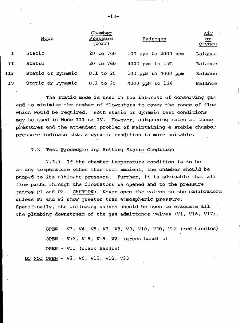
7 .2 Two modes of opera t ion a r e r equ i r ed t o cover t h e range of chamber t es t p re s su res . and maximum ope ra t ing cond i t ions over t h e range of p r e s s u r e s and range of mixture r a t i o s .
The fol lowing table shows t h e minimum
~
I
I1
I11
IV
Mode __u
-13-
Chamber p r e s s u r e
( t o r r )
&&
o x E e n or
S t a t i c 20 to 760 100 ppm to 4000 ppm B a L anue
S t a t i c 20 to 760 4000 ppm t o 15% Balancn
S t a t i c or Dynamic 0 .1 t o 20 100 ppm t o 4000 ppm Balance
Static or ~ynamlic 0.1 to 20 4000 pp~i to 15% Balance
The s t a t i c mode ks used in t h e i n t e r e s t of conserv ing ga?; and to minimize the number a€ flowrators t o cover t h e range of f l o w which would be requi red . Both static or dynamic test c o n d i t i o n s may he used i n M ~ d e EX1 or IV. However, ou tgass ing rates a t these pressures and t h e a t t a n d e n t problem of main ta in ing a stable chambe?- pressure i n d i c a t e t h a t a dynamic cond i t ion is more suitable.
c
7.3 xest Praeedure for Settinq Sta t i c Cpndition
7-3.1 If the chamber temperature c o n d i t i o n is t o be at any tmperatura other t han room ambient , t h e chamber should be puixpcd to its ul t ina te pressure, F u r t h e r , i t is a d v i s a b l e t h a t all. flow p a t h s through the flowrators be opened and t o t h e p res su re gauges PP and P2, Y CAUTXON: Never open t h e valves t o t h e calibrators unles s Pl and P2 shaw greater than atmaspheric p re s su re . Specifisal%y, the fol lowing valves should be open t o evacuate all t h e plumbing downstreiann of t h e gas admittance valves (V1, V16, V379
7.3.2 S t a r t blower and set temperature c o n t r o l f o r d e s i r e d temperature.
7.3.3 A f t e r chamber temperature has s t a b i l i z e d , t h e gas test condi t ions may be set .
7.3.4 An example, assuming a t e s t condi t ion follows:
'chamber = 500 t o r r
Mixture 15% H2; 85% O2
From t h e t a b l e of 7.2 t h i s de f ines a s t a t i c tes t . A t t h i s p o i n t , t h e oxygen/air s i d e of t h e c o n t r o l console and t h e hydrogen s i d e should be i s o l a t e d from each o the r and t h e chamber. This i s done by c l o s i n g V13, V15, V21 and V11,
Since a f lowra tor i s not requi red i n a s t a t i c mode, V3, V4, V5, v7, V8 and V22 can be c losed .
Ca lcu la t e , as follows, t h e p re s su re t o which t h e chamber must be r a i s e d wi th hydrogen (assume l o c a l ambient barometer of 760 t o r r ) :
ppH2 = mixture % H2 x chamber tes t p re s su re
ppH2 = .15 x 500 = 75 t o r r
Th i s i n d i c a t e s t h a t hydrogen should be admitted u n t i l t h e chamber p r e s s u r e i s increased from i t s l o w u l t i m a t e up t o a p re s su re of 75 t o r r and then a i r o r oxygen added t o raise t h e p re s su re t o 500 t o r r . The procedure i s t o r e l i e v e a l l c o n t r o l from PR2
-15-
(overboard dump r e g u l a t o r ) , i nc rease p r e s s u r e on P R 1 , open t h r o t t l e va lve V 1 u n t i l a p o s i t i v e p re s su re i s read on P1.
Then, wh i l e observing chamber pressure on t h e e l e c t r o n i c manometer, increase t h e p re s su re t o 75 t o r r (75 mm) by use of V 1 1 .
The hydrogen s i d e of the c o n t r o l console should now be i s o l a t e d by c l o s i n g V 1 , V9 and V 2 0 .
The next s t e p i s s i m i l a r t o t h a t descr ibed f o r admi t t ing hydrogen. I f oxygen i s chosen as t h e ba lance of t h e
mixture , i n c r e a s e PR3, open V16 and V 1 3 u n t i l P2 shows a p o s i t i v e pressure . Then open V 2 1 and V l l u n t i l t he chartiber p re s su re i n d i c a t e s 500 t o r r , as measured by the p r e c i s i o n bourdon tube p r e s s u r e gauge. If a i r had b e e n chosen, the va lv ing used would be PR4, 7717, V 2 1 and V11 .
The mixture r a t i o i s now 15% H2 i n oxygen (or a i r ) a t 500 to r r .
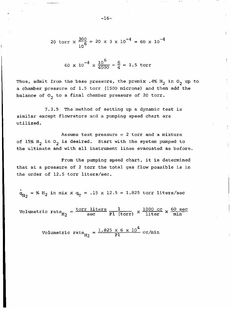
The above procedure would be s i m i l a r i f t h e 300 ppm of H2 i n oxygen w e r e requi red a t a pressure of 20 t o r r except t h e .4% mixture of H2 i n oxygen woul be requi red as t h e t es t gas on t h e hydrogen s i d e of t h e syst m and account must be made of t h e q u a n t i t y of O2 i n t h e mixture which i s be ing admitted.
P a r t s H, L X ( f i n a l mix)
P r e s s ( f i n a ~ mix) P a r t s f i n a l mix = PPH2
-16-
30" - 20 x 3 x = 60 x 10 -4 20 t o r r x - LO
lo6 = 1.5 t o r r 6 0 x 1 0 x ~ = ~ -4
Thus, admit from the b a s e p re s su re , t h e premix .4% Ha i n O2 up t o a chamber p res su re of 1.5 t o r r (1500 microns) and then add t h e ba lance of O2 t o a f i n a l chamber pressure of 20 t o r r ,
7.3.5 The method of s e t t i n g up a dynamic test i s s i m i l a r except f lowra to r s ar,d a pumping speed chart are u t i l i z e d .
Assume tes t pressure = 2 t o r r and a mixture of 15% H2 i n O2 is des i r ed . t h e u l t i m a t e and wi th a l l instrument l i n e s evacuated as before .
S ta r t w i t h the system pumped t o
From t h e pumping speed c h a r t , it i s determined t h a t a% a p r e s s u r e of 2 t o r r t h e t o t a l gas f l o w p o s s i b l e i s i n t h e o rde r of 1 2 . 5 t o r r liters/sec.
= % H2 i n mix x g~ -" -15 x 12 .5 = 1.825 t o r r liters/sec qH2
1000 cc 60 sec l i t e r min X
t o r r l i ters 1 ~1 ( t o r r ) Volumetric ra te = H2 sec
4 1.825 x 6 X 18 P 1 volumetric r a t e =
H2
-17-
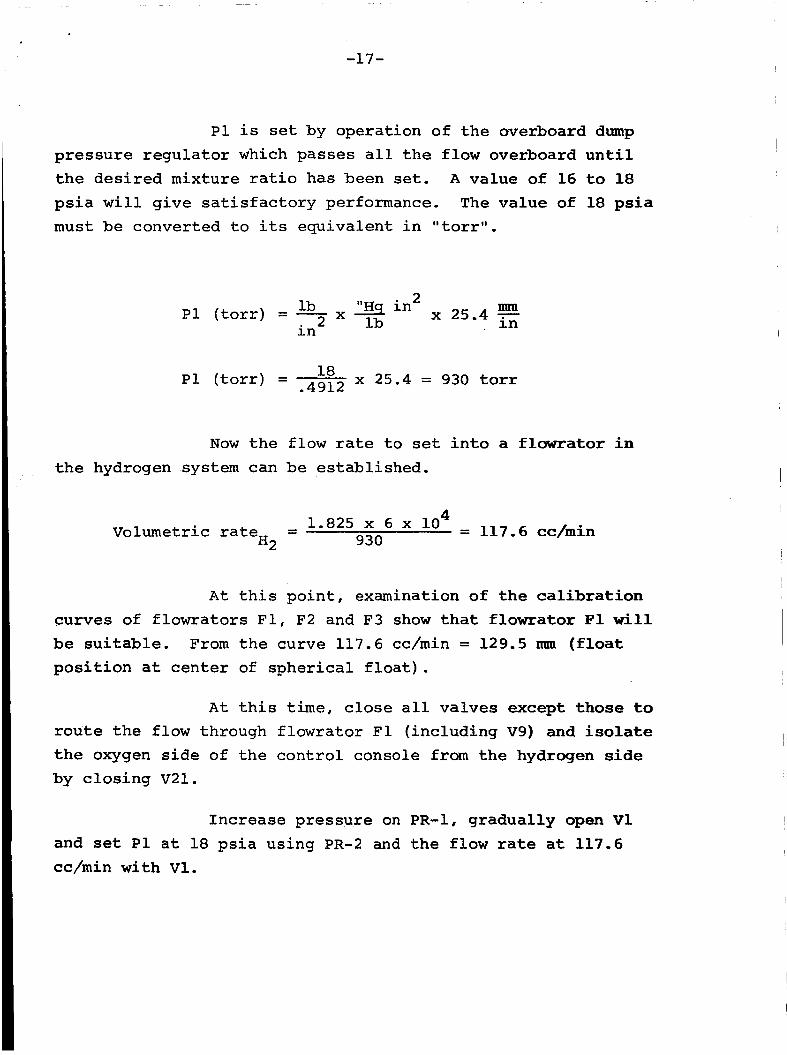
P1 i s set by operat ion of t h e overboard dump p r e s s u r e r e g u l a t o r which passes a l l t h e f l o w overboard u n t i l t h e d e s i r e d mixture r a t i o has been set. A value of 16 t o 18
p s i a w i l l g i v e s a t i s f a c t o r y performance. The va lue of 18 psia must be converted t o i t s equiva len t i n "torr".
mm 2 lb "Hg i n i n
x 25.4 in lb P1 ( t o r r ) = - 2
l8 .4912 x 25.4 = 930 t o r r ~1 ( t o r r ) =
Now t h e flow rate t o set i n t o a flawrator i n t h e hydrogen system can be established.
4 lo = 117.6 cc/min
930 Volumetric r a t e = H2
A t t h i s p o i n t , examination of t h e c a l i b r a t i o n curves of f lowra to r s F1, F2 and F 3 show t h a t flowrator F1 Wi l l be s u i t a b l e . From t h e curve 117.6 cc/min = 129.5 mm (float p o s i t i o n a t c e n t e r of s p h e r i c a l f l o a t ) .
A t t h i s t i m e , c l o s e a l l va lves except t h o s e t o r o u t e t h e flow through f lowra tor F1 ( inc luding V9) and isolate t h e oxygen s i d e of t h e c o n t r o l console from t h e hydrogen side by c l o s i n g V21 .
I nc rease p re s su re on PR-1, gradua l ly open V 1
and set P1 a t 18 p s i a using PR-2 and t h e f l o w rate a t 117.6 cc/min wi th V1.
-18-
us ing t h r o t t l e va lve V16, a d j u s t f l o w on F4 t o set p o i n t of
D o n o t open V l l a t t h i s po in t .
Now t h e oxygen flow ra te must be set.
I f 12.5 t o r r liters/sec x -15 i s t h e hydrogen
I f l o w ra te , the ba lance i s oxygen. Thus,
;IO2 = 12-5 - 1.825 = 10.675 t o r r liters/sec
and
4 10.675 x 6 x 10 cc,min V o l u m e t r i c r a t e = 02 p2
S ince P2 w i l l e q u i l i b r a t e with P l (except f o r s l i g h t p r e s s u r e drop i n measuring l i n e ) , P2 w i l l be 930 t o r r a s w a s P1. Thus,
A t t h i s p o i n t , examination of t h e curve f o r flowrator I F4 i n d i c a t e s a set p o i n t of 41.5 nun w i l i y i e i d 685.5 cc/min of
oxygen.
Thus t h e mixture r a t i o is now set , b u t a l l of t h e mixture is being dumped overboard. g radua l ly opened, while observing t h e e l e c t r o n i c manometer u n t i l t h e chamber p re s su re is increased t o 2 t o r r (2000 microns) .
A t t h i s p o i n t t h r o t t l e va lve V 1 1 i s I
~
-19-
C a l i b r a t i o n of t h e device wi th in the chamber can now be e f f ec t ed .
7.3.6 C a l i b r a t i o n of t h e f lowra to r s
A c a l i b r a t i o n curve of t h e f lowra to r s should be made before any t e s t i n g i s i n i t i a t e d , and a lso on a periodic basis t o i n s u r e no leaks have developed i n t h e system t o negate t h e p r i o r c a l i b r a t i o n , fol lowing manner,
A c a l i b r a t i o n curve may be made i n t he
7.3.6.1 Two s i z e s of volumetr ic c a l i b r a t o r s are provided fo r t h e hydrogen gas admittance system, C a l i b r a t o r C 1
should be used f o r F1 and C2 f o r F2 and F3. The vacuum pump need n o t be used during t h i s operat ion for a11 flow will be
passed through t h e overboard dump r egu la to r and thence ou t of t h e t es t a rea .
7.3.6.2 For c a l i b r a t i n g F1, i n i t i a t e a f l o w c i r c u i t such t h a t a l l gas from V1 goes through F1 and t h a t P1 can be measured. Choose increments of 10 mm d e f l e c t i o n of t h e spherical f loa t . S e t PR-2 such tha t P1 measures 18 p s i a . For each set p o i n t on F1, ob ta in a volumetric f l o w r a t e ( c u b i c centimeter/minute). "c losure" of V4 and "opening" of V2. U s e t h e mercury seal r i n g o r o t h e r convenient datum on the p i s t o n i n t h e volumetr ic ra te meter. Measure t h e volume a s a funct ion of t i m e over t h e l a r g e s t vol- ume t o minimize e r r o r .
For F1 t h i s i s accomplished by simultaneous
7 - 3 - 6 . 3 A l l other f lowra to r s may be calibrated i n a s i m i l a r manner us ing C2 in conjunction w i t h F2 and F3, C3 i n conjunct ion w i t h F4 and C4 i n conjunction wi th F5,
7-3-6.4 WARNENG: Gas f l o w must be stopped to t he c a l i b r a t o r before t h e t o p of t h e p i a t a n t r a v e l i s reached, o r t h e mercury seal w i l l be blown out of t h e t o p of t he bore tube.
7.3.6.5 Venting of t he c a l i b r a t i o n gas from t h e volumetr ic device i s accomplished b y opening the toggle va lve a t the base of t h e calibrator. vented t o the downstream side of PR-2 s i n c e this gas (hydrogen) could r ep resen t a hazard t o the room environment. C a l i b r a t o r s c3 and C4 are vented s i m i l a r l y b u t t o t h e room environment because of t h e non-hazardous n a t u r e of t h e gas,
I n t h e case of C1 and C2, t he gas i s
-21-
8 a 0 MAINTENANCE
8.1 Mechanical Pump
Pe r iod ic checks sheuld be made of t h e oil l e v e l through
t h e view windows i n t h e oil r e se rvo i r . only Cel lu lube 220 a s make-up f o r loss , contaminate t h e mechanical pump and cause loss i n ability t o reach l o w u l t i m a t e vacuum pressures . I t i s recommended, there- fore, t h a t e i t h e r t h e pump be operated on "gas b a l l a s t " for
If oil i s required, use
I Water vapor will
I I
I
I I 1 2 t o 16 hours b e f o r e a t e s t o r better t o be operated cont inuously
when n o t be ing used w i t h a gas n i t rogen purge set at approximately 300 microns. The purge p res su re i s set by opening t h e purge valve on t h e r i g h t rear of t h e c o n t r o l panel. suppl ied a t 2 t o 5 p s i g ,
I Gas n i t r o g e n should be
8 . 2 Vacuum Chamber
The vacuum chamber i n t e r i o r should be cleaned p e r i o d i c a l l y w i t h ace tone and methanol t o remove o i l s and water vapor from t h e su r faces .
8 . 3 Follow manufacturers ' recommendations wi th r e s p e c t t o other equipment suppl ied , are under s e p a r a t e cover.
Maintenance and ope ra t ing i n s t r u c t i o n s
-22-
9.0 SPARE PARTS
9.1 inven to r i ed :
I t i s recommended t h a t t h e folowing spare par ts be
9.1.1 Gasket - copper 1-1/2" I . D . , V a r i a n #953-5014
9.1.2 O-ring - s i l i c o n e , P a r k e r #2-388
9.1.3 Mechanical Pump O i l - Cel lu lube #220, S t a u f f e r Chemical Company
9.1.4 Rupture D i s c - Size 1-1/2" 18-20 p s i g b u r s t p r e s s u r e , F ike , B l u e Spr ings , Mo.
9-1.5 Rupture D i s c - Size 4" 18-20 p s i g b u r s t p r e s s u r e , F ike , B l u e Spr ings , M o .
9.1.6 Vacuum Support - Size 1-1/2" t e f l o n coated, F ike , B l u e Spr ings , M o .
9.1.7 Vacuum Support - Size 4" t e f l o n coa ted , F ike ,
9.1.8
Blue Springs, Mo,
B o l t s - Machine 1/4-28 x 1-1/4 type 18-8 s ta in less steel
9.1.9 N u t s - H e x 1/4-28
9.1.10 Bol t - Machining, Mercury A i r Products #MHH3001-624-56-S
9.1.11 Nut - Hex, Mercury A i r Products #MNlO5-H-S