This article was downloaded by: [Dalhousie University] On: 26 September 2012, At: 22:28 Publisher: Taylor & Francis Informa Ltd Registered in England and Wales Registered Number: 1072954 Registered office: Mortimer House, 37-41 Mortimer Street, London W1T 3JH, UK Materials and Manufacturing Processes Publication details, including instructions for authors and subscription information: http://www.tandfonline.com/loi/lmmp20 Fabrication of Ni-Plaque-Based Manganese Dioxide Electrodes for Electrochemical Supercapacitors Yaohui Wang a , Quan Min Yang b & Igor Zhitomirsky a a Department of Materials Science and Engineering, McMaster University, Hamilton, Ontario, Canada b Vale Canada Limited, Mississauga, Ontario, Canada Accepted author version posted online: 26 May 2011.Version of record first published: 08 Apr 2011. To cite this article: Yaohui Wang, Quan Min Yang & Igor Zhitomirsky (2011): Fabrication of Ni-Plaque-Based Manganese Dioxide Electrodes for Electrochemical Supercapacitors, Materials and Manufacturing Processes, 26:6, 846-854 To link to this article: http://dx.doi.org/10.1080/10426914.2010.536937 PLEASE SCROLL DOWN FOR ARTICLE Full terms and conditions of use: http://www.tandfonline.com/page/terms-and-conditions This article may be used for research, teaching, and private study purposes. Any substantial or systematic reproduction, redistribution, reselling, loan, sub-licensing, systematic supply, or distribution in any form to anyone is expressly forbidden. The publisher does not give any warranty express or implied or make any representation that the contents will be complete or accurate or up to date. The accuracy of any instructions, formulae, and drug doses should be independently verified with primary sources. The publisher shall not be liable for any loss, actions, claims, proceedings, demand, or costs or damages whatsoever or howsoever caused arising directly or indirectly in connection with or arising out of the use of this material.
Transcript
This article was downloaded by: [Dalhousie University]On: 26 September 2012, At: 22:28Publisher: Taylor & FrancisInforma Ltd Registered in England and Wales Registered Number: 1072954 Registered office: Mortimer House,37-41 Mortimer Street, London W1T 3JH, UK
Materials and Manufacturing ProcessesPublication details, including instructions for authors and subscription information:http://www.tandfonline.com/loi/lmmp20
Fabrication of Ni-Plaque-Based Manganese DioxideElectrodes for Electrochemical SupercapacitorsYaohui Wang a , Quan Min Yang b & Igor Zhitomirsky aa Department of Materials Science and Engineering, McMaster University, Hamilton, Ontario,Canadab Vale Canada Limited, Mississauga, Ontario, Canada
Accepted author version posted online: 26 May 2011.Version of record first published: 08 Apr2011.
To cite this article: Yaohui Wang, Quan Min Yang & Igor Zhitomirsky (2011): Fabrication of Ni-Plaque-Based Manganese DioxideElectrodes for Electrochemical Supercapacitors, Materials and Manufacturing Processes, 26:6, 846-854
To link to this article: http://dx.doi.org/10.1080/10426914.2010.536937
PLEASE SCROLL DOWN FOR ARTICLE
Full terms and conditions of use: http://www.tandfonline.com/page/terms-and-conditions
This article may be used for research, teaching, and private study purposes. Any substantial or systematicreproduction, redistribution, reselling, loan, sub-licensing, systematic supply, or distribution in any form toanyone is expressly forbidden.
The publisher does not give any warranty express or implied or make any representation that the contentswill be complete or accurate or up to date. The accuracy of any instructions, formulae, and drug doses shouldbe independently verified with primary sources. The publisher shall not be liable for any loss, actions, claims,proceedings, demand, or costs or damages whatsoever or howsoever caused arising directly or indirectly inconnection with or arising out of the use of this material.
Fabrication of Ni-Plaque-Based Manganese DioxideElectrodes for Electrochemical Supercapacitors
Yaohui Wang1, Quan Min Yang
2, and Igor Zhitomirsky
1
1Department of Materials Science and Engineering, McMaster University, Hamilton, Ontario, Canada2Vale Canada Limited, Mississauga, Ontario, Canada
Chemical and electrochemical impregnation methods have been developed for the fabrication of manganese dioxide electrodes for electrochemicalsupercapacitors using Ni plaques as current collectors. The methods enabled the synthesis of manganese dioxide in-situ in pores of Ni plaques.The chemical method was based on the reduction of KMnO4 solutions with isopropanol. Cathodic galvanostatic method and reverse pulseelectrosynthesis method were investigated for electrochemical impregnation. The material loading was varied by the variation of the numberof the dipping-reduction procedures in the chemical precipitation method or by variation of charge passed in the electrochemical methods. Themicrostructures of the electrodes prepared using different methods were studied by scanning electron microscopy (SEM). The electrochemicalbehavior of the electrodes was studied using cyclic voltammetry and impedance spectroscopy. The electrodes exhibited capacitive behaviorin the 0.5M Na2SO4 electrolyte in a voltage window of 0–0.9V. The results obtained by different methods were compared. The chemicalprecipitation method offered the advantage of higher specific capacitance, whereas electrochemical methods allowed higher material synthesis rate.The highest specific capacitance of 236F g−1 was obtained at a scan rate of 2mV s−1. The specific capacitance decreased with increasing scanrate. Testing results showed that the electrodes prepared by chemical and electrochemical in-situ precipitation methods can be used for applicationin electrochemical supercapacitors.
Porous current collectors, such as Ni plaques and foams,are widely used in industry for the fabrication of electrodesfor rechargeable batteries [1, 2]. Ni plaques are currentcollectors of choice for battery applications demandinghigh power and reliability, along with long cycle life,such as batteries for aerospace and railway applications,power tools, and portable electronics. Significant advancesin the development of Ni plaques were achieved by the useof filamentary Ni particles with high surface area, whichprovided improved contact with active material [3, 4]. Thepore size of Ni plaques is usually much smaller comparedto that of other industrial current collectors, such as Nifoams. The smaller pore size decreased the distance forelectrons to travel from the current collector into the activematerial during cell discharge and, consequently, improvedthe discharge rate characteristics [3, 4]. Ni hydroxide is usedas a positive electrode material for a number of alkalinesecondary cells such as Ni/Cd, Ni/Fe, Ni/Zn, and Ni/MHcells [5]. Due to the small pore size of Ni plaques, theimpregnation of the plaques with Ni hydroxide was achievedby in-situ chemical or electrochemical synthesis in poresusing Ni nitrate solutions [5–7]. Chemical impregnation isbased on multiple dipping of the plaques in the Ni nitratesolutions and treatment in basic solutions. Electrochemical
Received October 1, 2010; Accepted October 30, 2010Address correspondence to I. Zhitomirsky, Department of Materials
Science and Engineering, McMaster University, 1280 Main Street West,Hamilton, ON L8S 4L7, Canada; E-mail: [email protected]
synthesis is based on the cathodic electrogenerated basemethod [8, 9].A new wave of interest in the use of Ni plaques
as current collectors in electrochemical energy storagedevices is related to the development of electrochemicalsupercapacitors (ES) [10] for high power applications inelectric and hybrid vehicles. Ni plaques are especiallyattractive for the fabrication of advanced ES electrodes,containing manganese dioxide as an active material. Theinterest in manganese dioxide is related to low cost of thismaterial, which exhibited high specific capacitance (SC) inenvironmentally friendly aqueous electrolytes [10, 11]. Thecharging mechanism of manganese dioxide is described bythe following reaction [12]:
MnO2 + A+ + e− ↔ MnO2A� (1)
where A+ = Li+, Na+, K+, H+. Equation (1) indicatesthat high electronic and ionic conductivity are necessary inorder to utilize the high theoretical SC (1370F g−1 [13]) ofmanganese dioxide. However, the electronic conductivityof manganese dioxide is low. As a result, the specificcapacitance decreased significantly with increasing filmthickness [14, 15]. Therefore, it is expected that similar tothe battery technology, porous Ni plaques with high surfacearea can provide improved contact with active material andhigher conductivity of ES electrodes.The important task is the development of chemical and
electrochemical methods for the impregnation of Ni plaqueswith manganese dioxide. A complicating factor in thefabrication of manganese dioxide is the lack of stable Mn
846
Dow
nloa
ded
by [
Dal
hous
ie U
nive
rsity
] at
22:
28 2
6 Se
ptem
ber
2012
FABRICATION OF MANGANESE DIOXIDE ELECTRODES 847
(IV) precursors in aqueous solutions. Manganese dioxidepowders can be formed by reduction of KMnO4 solutionsusing various reducing agents such as Mn2+ salts andorganic acids [16, 17]. However, the use of Mn2+ salts andorganic acids for the in-situ synthesis in pores of Ni plaquespresents difficulties, attributed to the removal of anions andorganics from the pores after the chemical precipitation ofmanganese dioxide. In the previous investigations [18, 19]it was shown that thin manganese dioxide films with goodcapacitive behavior can be obtained by cathodic reductionof Mn7+ species using solutions of KMnO4 or NaMnO4salts. The latest achievement in this process was attainedby the use of reverse pulse electrosynthesis, which enabledthe formation of porous films with improved capacitivebehavior [20].The goal of this investigation was the development of
chemical and electrochemical strategies for the impregnationof Ni plaques and investigation of the capacitive behaviorof the prepared electrodes for application in ES. The resultspresented below indicated that isopropanol can be used as areducing agent for the impregnation by a chemical method.In this approach, the problem related to the washing of theprepared material and removal of the reducing agent andreaction products can be avoided. Cathodic electrosynthesisfrom solutions of KMnO4 salts has been utilized forthe electrochemical impregnation, using galvanostatic orreverse pulse deposition techniques. The results obtained bydifferent methods were analyzed and compared.
Experimental procedures
The addition of 100mL of isopropanol to 100mL ofaqueous 0.1M KMnO4 solutions resulted in the formationof dark-brown precipitate. The precipitate was filtered,washed with isopropanol-water mixture (50 vol% of water)and dried in the air. The investigation of the precipitateshowed that isopropanol can be used as a reducing agentfor the fabrication of manganese dioxide from KMnO4solutions. This approach has been further utilized for thereduction of KMnO4 solutions in similar conditions in poresof Ni plaques and fabrication of electrodes by chemicalimpregnation of Ni plaques.Commercial Ni plaques were supplied by Vale Canada.
Chemical impregnation was achieved by dipping theplaques into aqueous 0.1M KMnO4 solution during 15min,reduction in the isopropanol-water mixture (50 vol% water)during 30min and drying in the air. The procedureswere repeated, and mass gain was investigated as afunction of the number of the dipping-reduction procedures.Electrodeposition was performed from 20mM KMnO4solutions galvanostatically at a cathodic current density of5mA cm−2 or in reverse pulse regime at a cathodic currentdensity of 5mA cm−2 for 2min and then an anodic currentdensity of 2mA cm−2 for 1min.Electron microscopy investigations were performed using
a JEOL 2010F transmission electron microscope (TEM) anda JEOL JSM-7000F scanning electron microscope (SEM).The X-ray diffraction (XRD) studies were performed usinga powder diffractometer (Nicolet I2, monochromatizedCuK� radiation) at a scanning speed of 0�5� min−1.Thermogravimetric analysis (TGA) and differential thermal
analysis (DTA) were carried out in air at a heating rateof 5�C min−1 using a thermoanalyzer (Netzsch STA-409).Chemical analysis was performed using inductively coupledplasma (ICP) optical emission spectroscopy (OES) (Vista-PRO, Varian). The mean oxidation state (MS) of manganesewas investigated using the iodometric method [21].Fourier transform infrared spectroscopy (FTIR) studies wereperformed using Bio-Rad FTS-40 instrument.Capacitive behavior of the electrodes was studied
using a potentiostat (PARSTAT 2273, Princeton AppliedResearch) controlled by a computer using a PowerSuiteelectrochemical software. Electrochemical studies wereperformed using a standard three-electrode cell containing0�5MNa2SO4 aqueous solution, degassed with purifiednitrogen gas. The surface area of the working electrodeswas 1 cm2. The counter electrode was a platinum gauze, andthe reference electrode was a standard calomel electrode(SCE). Cyclic voltammetry (CV) studies were performedwithin a potential range of 0–0.9V versus SCE at scan ratesof 2–100mV s−1. The SC was calculated using half theintegrated area of the CV curve to obtain the charge (Q), andsubsequently dividing the charge by the mass of the activematerial (m) and the width of the potential window (�V):
C = Q/m�V� (2)
Impedance spectroscopy investigations were performed inthe frequency range of 0.1Hz–100kHz at voltage of 5mV.
Results and discussion
It is suggested that the following redox reaction resultedin the reduction of KMnO4 and formation of manganesedioxide:
2MnO−4 + 3�CH3�2CH−OH+ 2H+
→ 2MnO2 + 3�CH3�2CO+ 4H2O� (3)
This is in good agreement with the results of otherinvestigations, which showed that the oxidation ofisopropanol resulted in the formation of acetone [22, 23].The XRD pattern of as-precipitated manganese dioxide(Fig. 1) indicated that the material was mainly amorphous.Small diffraction peaks can be attributed to the birnessitephase (JCPDS file 87-1497). The peaks of the birnessitephase became more distinct after annealing at 200 and300�C. It is suggested that annealing resulted in thecrystallization of an amorphous phase. Further increase inthe annealing temperature resulted in enhanced intensity ofthe peaks of the birnessite phase. According to the literature,the birnessite has near-MnO2 stoichiometry with a formulagenerally expressed [24] as AxMnO2+y�H2O�z, where Arepresents an alkali metal cation. The average oxidationstate of Mn usually falls [24] between 3.6 and 3.8, whichrepresents a predominance of Mn4+ with minor amount ofMn3+. ICP studies showed that manganese dioxide powdercontained K with the Mn/K atomic ratio of 3.1. The MS ofmanganese was found to be 3.63.The FTIR spectrum for as-prepared manganese dioxide
(Fig. 2) showed a broad peak centered at 3430 cm−1,
Dow
nloa
ded
by [
Dal
hous
ie U
nive
rsity
] at
22:
28 2
6 Se
ptem
ber
2012
848 Y. WANG ET AL.
Figure 1.—X-ray diffraction patterns for the powder prepared by reductionof KMnO4 solution with isopropanol: (a) as-precipitated and after annealingduring 1 h at different temperatures, (b) 200�C, (c) 300�C, (d) 400�C, and (e)500�C.
which can be attributed to the vibration of OH groups ofadsorbed water molecules [25, 26]. The bands at 1628,1540, and 1047 cm−1 represented the vibrations associatedwith interactions of Mn with OH, O, and K [27, 28].The adsorptions at 1384 and 1258 cm−1 were attributedto the vibrations of adsorbed isopropanol [29, 30]. Thebands at 450 and 512 cm−1 are characteristic adsorptions ofbirnessite, related to the Mn–O stretching vibration of theMnO6 interlayer [25, 31].TGA data (Fig. 3) showed a sharp reduction in sample
mass below 250�C, and then the mass decreased slowlywith increasing temperature. The observed mass loss of10.2wt% at 250�C and a broad endotherm around 100�Cin the corresponding DTA data could be related to theliberation of adsorbed water. The broad exotherm in theDTA data in the range of 150–250�C can be attributed tothe crystallization of an amorphous phase in agreement withthe results of the XRD study (Fig. 1). The total mass lossat 800�C was found to be 15.91wt%.
Figure 2.—FTIR spectrum for the powder, prepared by reduction of KMnO4
solution with isopropanol.
Figure 3.—(a) TGA and (b) DTA data for the powder, prepared by reductionof KMnO4 solution with isopropanol.
TEM study showed that as-prepared manganese dioxidepowders consisted of nanoparticles with diameter in therange of 20–50 nm (Fig. 4). The inset in Fig. 4 is aselected area electron diffraction pattern, which indicatedthat as-prepared powders contained polycrystals. However,the TEM data coupled with the results of XRD studiesshowed that powders contained a significant amount of anamorphous phase.Low magnification SEM image [Fig. 5(A)] of the powder
showed large agglomerates with typical size of 1–20�m.The SEM image at higher magnification [Fig. 5(B)] showedthat agglomerates consisted of nanoparticles in agreementwith the TEM data. It is suggested that drying of theas-precipitated manganese dioxide nanoparticles resulted intheir agglomeration. Such agglomerated powders cannotbe used for the impregnation of Ni plaques shown in[Figs. 6(A) and 6(B)]. Therefore, in order to impregnate Niplaques with active material, the synthesis of manganesedioxide was performed in-situ in pores of the plaques.Commercial Ni plaques used in this study consisted
of a perforated Ni foil and sintered filamentary Niparticles, which formed a porous network. [Figs. 6(A)and 6(B)] show SEM images of the surface of a Niplaque at different magnifications. The plaques exhibited
Figure 4.—TEM image of the powder prepared by reduction of KMnO4
solution with isopropanol. The insert shows a selected area electron diffractionpattern.
Dow
nloa
ded
by [
Dal
hous
ie U
nive
rsity
] at
22:
28 2
6 Se
ptem
ber
2012
FABRICATION OF MANGANESE DIOXIDE ELECTRODES 849
Figure 5.—(A) and (B): SEM images of the as-precipitated powder at differentmagnifications.
porous microstructure with pore sizes in the range of0–20�m [Fig. 6(A)]. The SEM image obtained at highermagnification [Fig. 6(B)] showed that the size of Ni particleswas in the range of 0.5–2�m. The porosity and conductivityof commercial Ni plaques are beneficial for their applicationas current collectors of ES.Ni plaques were impregnated with manganese dioxide
by dipping in KMnO4 solutions and reduction of theimpregnated material with isopropanol. Figure 7(A) showsmass gain of a Ni plaque as a function of the number of thedipping-reduction procedures (N). The observed mass gainindicated that the reduction of KMnO4 can be performedin-situ in the pores of Ni plaques. The mass gain increasedin the range of 0–5mg cm−2 with increasing N, indicatingthe possibility of the fabrication of electrodes with differentmaterial loadings.The Ni plaques impregnated with manganese dioxide
using the dipping-reduction procedure were studied bySEM. Figure 6(C),(D) shows typical SEM images ofthe Ni plaques after impregnation. Low magnificationimage [Fig. 6(C)] of the plaque with material loadingof 4�7mg cm−2 showed that the impregnation resultedin a reduced porosity, compared with unloaded plaques[Fig. 6(A)]. However, only relatively small pores with poresize below 1�m were closed, whereas large number of poreswith diameters of 1–20�m remained open. In this process,open pores of the plaques provided a space for impregnationduring the next dipping-reduction step. Further increase inmaterial loading resulted in a decreased porosity.The SEM image at a higher magnification [Fig. 6(D)]
showed that dipping-reduction procedures resulted in the
Figure 6.—SEM images of Ni plaques at different magnifications: (A) and (B) before impregnation, and (C) and (D) after impregnation using dipping-reductionmethod, mass loading 4.7mgcm−2.
Dow
nloa
ded
by [
Dal
hous
ie U
nive
rsity
] at
22:
28 2
6 Se
ptem
ber
2012
850 Y. WANG ET AL.
Figure 7.—Mass of manganese dioxide (A) impregnated into a Ni plaqueusing a dipping–reduction method versus number of dippings, (B) (a)impregnated into a Ni plaque and (b) deposited on a Ni foil versus chargepassed using cathodic electrodeposition, and (C) impregnated into a Ni plaqueversus charge passed during cathodic pulses of electrodeposition in the reversepulse regime.
formation of manganese dioxide coatings on Ni particles.The precipitation of manganese dioxide on Ni particlescan explain the large number of open pores remainedafter impregnation. The SEM image [Fig. 6(D)] showed
that the size of manganese dioxide nanoparticles wason the nanometric scale. As pointed out above, theSEM images of the microstructure showed large poreswith diameter of 1–20�m between coated Ni particles[Fig. 6(C)]. Such electrode microstructure is beneficial forapplication in ES. Recent studies highlighted the advantagesof porous nanostructured coatings, which can provide highsurface area for electrochemical reactions [32]. However,it was shown that large pores are necessary for improvedelectrolyte access to the active material [32]. The formationof nanostructured manganese dioxide coating on Ni particlesenabled good contact of the active material and currentcollector. As a result, electrodes showed good capacitivebehavior, described below.Ni plaques were also impregnated galvanostatically by
cathodic reduction of MnO−4 (Mn7+) species. The reduction
mechanism was described in previous investigations[18, 19]:
MnO−4 + 2H2O+ 3e− → MnO2 + 4OH−� (4)
Figure 7(B) shows deposits mass of impregnated materialas a function of charge passed. The deposition yieldincreased with increasing charge passed. Therefore, theamount of the impregnated material can be controlled.The mass of impregnated material after 30 min ofelectrosynthesis at a current density of 5mAcm−2 wascomparable with that obtained after 25 dipping-reductionprocedures. The deposition yield was also studied usingNi foil substrates. However, the slope of the deposit massversus charge passed curve was lower, compared to that
Figure 8.—SEM images of Ni plaques at different magnifications after impregnation with manganese dioxide using (A) and (B) cathodic electrolytic deposition,and (C) and (D) reverse pulse electrodeposition, mass loading 4�7mg cm−2.
Dow
nloa
ded
by [
Dal
hous
ie U
nive
rsity
] at
22:
28 2
6 Se
ptem
ber
2012
FABRICATION OF MANGANESE DIOXIDE ELECTRODES 851
obtained for Ni plaque substrates [Fig. 7(B), curve (a)].After 10 min of deposition, deposit spalling was observed,which resulted in a decrease in deposit mass [Fig. 7(B),curve (b)]. The deposition yield measurements presentedin Fig. 7(B) showed that much higher material loadingcan be achieved using Ni plaque substrates. This can beattributed to accumulation of the impregnated material inpores of Ni plaques. However, it should be noted thatdue to the use of anionic MnO−
4 species for cathodicelectrosynthesis, the kinetics of deposition is governedby MnO−
4 diffusion and electromigration [20]. Previousinvestigation showed the influence of adverse potentialgradient on the cathodic electrosynthesis of manganesedioxide from the solutions containing anionic MnO−
4species. It is suggested that the screening effect of Niplaques can reduce the adverse electromigration rate ofMnO−
4 in the plaque pores during electrosynthesis. Thiscan explain the higher electrosynthesis rate in pores of Niplaques [Fig. 7(B), curve (a) versus curve (b)].Electrosynthesis was also performed in a reverse pulse
regime. Figure 7(C) shows the deposition yield as a functionof cathodic charge passed. The comparison of the datapresented in Fig. 7(B),(C) showed that the impregnationrate in the reverse pulse regime was higher than that inthe galvanostatic regime. It is suggested that galvanostaticdeposition can result in electrolyte depletion in the electrodearea. Therefore, reverse pulse deposition can providereduced electrolyte depletion and a higher deposition rateduring the cathodic pulses.Figure 8 shows SEM images of Ni plaques impregnated
using electrochemical methods. The SEM analysis of thesurfaces of such plaques revealed reduced macroporositycompared to the plaque impregnated using dipping-reduction procedure [Fig. 6(C),(D)] for the same activematerial loading. The blocked macroporosity resultedin partial accumulation of manganese dioxide on theplaque surface, which was especially evident for theplaques impregnated galvanostatically [Fig. 8(A),(B)].The manganese dioxide accumulated on the surface ofgalvanostatically impregnated plaques showed cracked-mud morphology, which contained areas of relativelydense material [Fig. 8(B)]. The plaque, impregnated usingreverse pulse method showed larger number of unblockedmacropores [Fig. 8(C),(D)], compared to the plaquesimpregnated galvanostatically [Fig. 8(A),(B)].The capacitive behavior of the electrodes prepared
using different impregnation methods was studied in0�5MNa2SO4 solutions. Figure 9 shows typical CVsobtained at different scan rates. The box shape of theCVs indicated capacitive properties of the coatings in thevoltage window of 0–0.9V. The increase in material loadingresulted in increased area of the CVs (Fig. 10), whichwas related to increased capacitance of the electrodes. Thesamples prepared by dipping-reduction methods showedlarger CV areas, which indicated better capacitive behavior.The SC of the electrodes was calculated from the CVdata using Eq. (2). The comparison of the capacitivebehavior of the electrodes prepared using electrochemicalimpregnation methods showed higher SC of the electrodesprepared by reverse pulse deposition methods (Fig. 11).The highest SC was observed for electrodes prepared using
Figure 9.—CVs at scan rates of (a) 5, (b) 10, and (c) 20mV s−1 forthe electrodes prepared using (A) dipping-reduction method, (B) cathodicelectrodeposition, and (C) reverse pulse deposition with mass loadings of1�4mg cm−2.
dipping-reduction method at a scan rate of 2mV s−1. TheSC at a scan rate of 2mV s−1 varied in the range of215–236 F g−1 with variation in material loading in therange of 0.6–5mg cm−2. The SC decreased with increasingscan rate due to the electrolyte diffusion limitation inpores [32]. The results of SC measurements correlatewith SEM observations of microstructures of impregnatedplaques. The plaques prepared by the dipping–reductionmethod showed larger number of open macropores, whichprovided improved electrolyte access to the impregnatedactive material. This resulted in higher SC, especially athigh scan rate (Fig. 11).
Figure 10.—CVs at a scan rate of 10mV s−1 for the electrodes prepared by(A) dipping–reduction method, (B) cathodic electrodeposition, and (C) reversepulse electrodeposition with mass loadings: (a) 0.6 and (b) 4.7mgcm−2.
Dow
nloa
ded
by [
Dal
hous
ie U
nive
rsity
] at
22:
28 2
6 Se
ptem
ber
2012
852 Y. WANG ET AL.
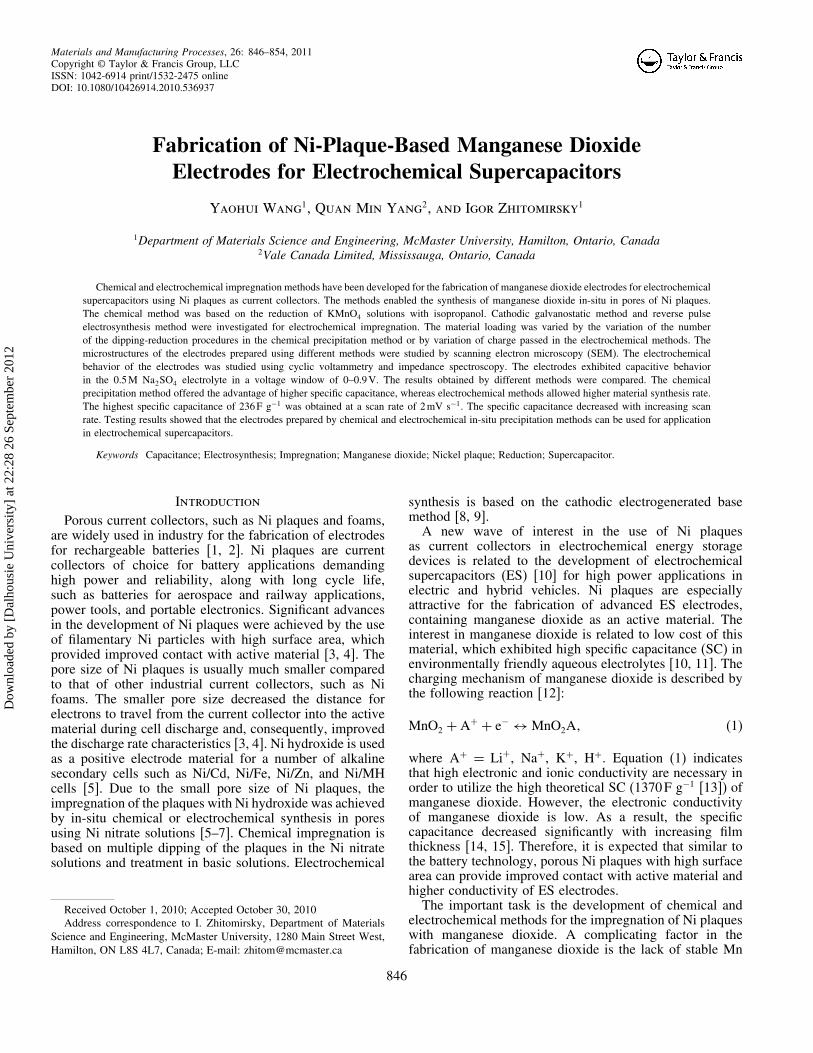
Figure 11.—SCs versus scan rate for the electrodes prepared using (a)dipping–reduction method, (b) cathodic electrodeposition, and (c) reverse pulseelectrodeposition method for mass loading of 1.4mgcm−2.
Turning again to the literature data on the capacitivebehavior of manganese dioxide, it should be noted that SCof impregnated electrodes was much lower compared tothe theoretical SC of 1370 F g−1 [13] and SC of 700 F g−1
reported for very thin films (∼1�g cm−2) [14]. However,it is known that SC decreases significantly with increasingfilm thickness [33] due to the low electronic conductivityof manganese dioxide. SC of 210–240 F g−1 was reportedfor material loading of 150–180�g cm−2 [34]. Previousinvestigations showed [35] that SC at a scan rate of 2 mV s−1
decreased from 400 F g−1 to 177 F g−1 when the film massincreased from 50�g cm−2 to 200�g cm−2. It is seen thatdue to the use of Ni plaque current collectors, the materialloading can be increased significantly and relatively highSC (236 F g−1) can be obtained at the same scan rate.The results of electrochemical impedance studies
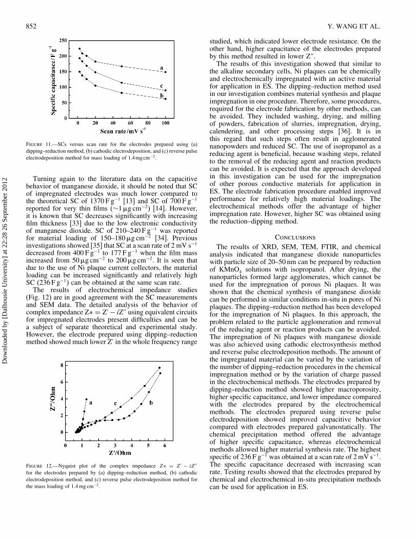
(Fig. 12) are in good agreement with the SC measurementsand SEM data. The detailed analysis of the behavior ofcomplex impedance Z∗ = Z′ − iZ′′ using equivalent circuitsfor impregnated electrodes present difficulties and can bea subject of separate theoretical and experimental study.However, the electrode prepared using dipping–reductionmethod showed much lower Z′ in the whole frequency range
Figure 12.—Nyquist plot of the complex impedance Z∗ = Z′ − iZ′′
for the electrodes prepared by (a) dipping–reduction method, (b) cathodicelectrodeposition method, and (c) reverse pulse electrodeposition method forthe mass loading of 1�4mg cm−2.
studied, which indicated lower electrode resistance. On theother hand, higher capacitance of the electrodes preparedby this method resulted in lower Z′′.The results of this investigation showed that similar to
the alkaline secondary cells, Ni plaques can be chemicallyand electrochemically impregnated with an active materialfor application in ES. The dipping–reduction method usedin our investigation combines material synthesis and plaqueimpregnation in one procedure. Therefore, some procedures,required for the electrode fabrication by other methods, canbe avoided. They included washing, drying, and millingof powders, fabrication of slurries, impregnation, drying,calendering, and other processing steps [36]. It is inthis regard that such steps often result in agglomeratednanopowders and reduced SC. The use of isopropanol as areducing agent is beneficial, because washing steps, relatedto the removal of the reducing agent and reaction productscan be avoided. It is expected that the approach developedin this investigation can be used for the impregnationof other porous conductive materials for application inES. The electrode fabrication procedure enabled improvedperformance for relatively high material loadings. Theelectrochemical methods offer the advantage of higherimpregnation rate. However, higher SC was obtained usingthe reduction–dipping method.
Conclusions
The results of XRD, SEM, TEM, FTIR, and chemicalanalysis indicated that manganese dioxide nanoparticleswith particle size of 20–50 nm can be prepared by reductionof KMnO4 solutions with isopropanol. After drying, thenanoparticles formed large agglomerates, which cannot beused for the impregnation of porous Ni plaques. It wasshown that the chemical synthesis of manganese dioxidecan be performed in similar conditions in-situ in pores of Niplaques. The dipping–reduction method has been developedfor the impregnation of Ni plaques. In this approach, theproblem related to the particle agglomeration and removalof the reducing agent or reaction products can be avoided.The impregnation of Ni plaques with manganese dioxidewas also achieved using cathodic electrosynthesis methodand reverse pulse electrodeposition methods. The amount ofthe impregnated material can be varied by the variation ofthe number of dipping–reduction procedures in the chemicalimpregnation method or by the variation of charge passedin the electrochemical methods. The electrodes prepared bydipping–reduction method showed higher macroporosity,higher specific capacitance, and lower impedance comparedwith the electrodes prepared by the electrochemicalmethods. The electrodes prepared using reverse pulseelectrodeposition showed improved capacitive behaviorcompared with electrodes prepared galvanostatically. Thechemical precipitation method offered the advantageof higher specific capacitance, whereas electrochemicalmethods allowed higher material synthesis rate. The highestspecific of 236 F g−1 was obtained at a scan rate of 2mV s−1.The specific capacitance decreased with increasing scanrate. Testing results showed that the electrodes prepared bychemical and electrochemical in-situ precipitation methodscan be used for application in ES.
Dow
nloa
ded
by [
Dal
hous
ie U
nive
rsity
] at
22:
28 2
6 Se
ptem
ber
2012
FABRICATION OF MANGANESE DIOXIDE ELECTRODES 853
Acknowledgment
The authors gratefully acknowledge the financial supportof the Natural Sciences and Engineering Research Councilof Canada.
References
1. Chani, V. I.; Yang, Q.; Wilkinson, D. S.; Weatherly, G. C. Effectof substrate pre-coating on adhesion of sintered nickel plaques forelectrode application in rechargeable batteries. Journal of PowerSources 2005, 142 (1–2), 370–381.
2. Yang, Q.M.; Ettel, V.A.; Babjak, J.; Charles, D.K.; Mosoiu, M.A.Pasted Ni�OH�2 electrodes using Ni powders for high-drain-rate,Ni-based batteries. Journal of the Electrochemical Society 2003,150 (4), A543–A550.
3. Cormier, E.; Wasmund, E.B.; Renny, L.V.; Yang, Q.M.; Charles,D. A new powder morphology for making high-porosity nickelstructures. Journal of Power Sources 2007, 171 (2), 999–1009.
4. Zaitsev, A.Y.; Wilkinson, D.S.; Weatherly, G.C.; Stephenson,T.F. The preparation of highly porous structures from filamentarynickel powders. Journal of Power Sources 2003, 123 (2),253–260.
5. Dixit, M.; Kamath, P.V.; Kumar, V.G.; Munichandraiah, N.;Shukla, A.K. An electrochemically impregnated sintered-nickelelectrode. Journal of Power Sources 1996, 63 (2), 167–171.
6. Nagarajan, G.S.; Ho, C.-H.; Van Zee, J.W. Mathematical modelfor predicting nonuniform electrochemical impregnation of nickelhydroxide. Journal of The Electrochemical Society 1997, 144 (2),503–510.
7. Sasaki, Y.; Yamashita, T. Effect of electrolytic conditions onthe deposition of nickel hydroxide. Thin Solid Films 1998, 334(1–2), 117–119.
8. Zhitomirsky, I.; Gal-Or, L. Electrochemical coatings. In:Intermetallic and Ceramic Coatings; Dahotre, N.B.; Sudarshan,T.S. (Eds.); Marcel Dekker: N.Y. 1999, 83–145.
9. Zhitomirsky, I. Cathodic electrodeposition of ceramic andorganoceramic materials. Fundamental aspects. Advances inColloid and Interface Science 2002, 97 (1–3), 277–315.
10. Lee, K.-T.; Lee, J.-F.; Wu, N.-L. Electrochemicalcharacterizations on MnO2 supercapacitors with potassiumpolyacrylate and potassium polyacrylate-co-polyacrylamidegel polymer electrolytes. Electrochimica Acta 2009, 54 (26),6148–6153.
11. Simon, P.; Gogotsi, Y. Materials for electrochemical capacitors.Nature Materials 2008, 7 (11), 845–854.
12. Athouel, L.; Moser, F.; Dugas, R.; Crosnier, O.; Belanger,D.; Brousse, T. Variation of the MnO2 birnessite structureupon charge/discharge in an electrochemical supercapacitorelectrode in aqueous Na2SO4 electrolyte. The Journal of PhysicalChemistry C 2008, 112 (18), 7270–7277.
13. Devaraj, S.; Munichandraiah, N. High capacitance ofelectrodeposited MnO2 by the effect of a surface-active agent.Electrochemical and Solid-State Letters 2005, 8 (7), A373–A377.
14. Pang, S.-C.; Anderson, M.A.; Chapman, T.W. Novel electrodematerials for thin-film ultracapacitors: Comparison of electro-chemical properties of sol-gel-derived and electrodepositedmanganese dioxide. Journal of the Electrochemical Society 2000,147 (2), 444–450.
15. Chin, S.-F.; Pang, S.-C.; Anderson, M.A. Material andelectrochemical characterization of tetrapropylammoniummanganese oxide thin films as novel electrode materials for
electrochemical capacitors. Journal of the Electrochemical Society2002, 149 (4), A379–A384.
16. Brousse, T.; Toupin, M.; Belanger, D. A hybrid activated carbon-manganese dioxide capacitor using a mild aqueous electrolyte.Journal of the Electrochemical Society 2004, 151 (4), 614–622.
18. Wei, J.; Nagarajan, N.; Zhitomirsky, I. Manganese oxide films forelectrochemical supercapacitors. Journal of Materials ProcessingTechnology 2007, 186 (1–3), 356–361.
19. Wei, J.; Zhitomirsky, I. Electrosynthesis of manganese oxidefilms. Surface Engineering 2008, 24, 40–46.
20. Jacob, G.M.; Zhitomirsky, I. Microstructure and properties ofmanganese dioxide films prepared by electrodeposition. AppliedSurface Science 2008, 254 (20), 6671–6676.
21. Murray, J.W.; Balistrieri, L.S.; Paul, B. The oxidation state ofmanganese in marine sediments and ferromanganese nodules.Geochimica et Cosmochimica Acta 1984, 48 (6), 1237–1247.
22. Fujihira, M.; Tasaki, S.; Osa, T.; Kuwana, T. Photo-assistedelectrochemical oxidation of isopropanol to acetone on achemically modified electrode. Journal of ElectroanalyticalChemistry 1983, 150 (1–2), 665–672.
23. He, J.-G.; Shi, L.; Jiang, Y.-Y. Oxidation of isopropanol andethanol by a magnesium oxide-supported polysilazane-platinumcomplex catalyst. Reactive Polymers 1991, 15, 131–134.
25. Luo, J.; Huang, A.; Park, S.H.; Suib, S.L.; O’Young, C.-L.Crystallization of sodium birnessite and accompanied phasetransformation. Chemistry of Materials 1998, 10 (6), 1561–1568.
26. Yang, R.; Wang, Z.; Dai, L.; Chen, L. Synthesis andcharacterization of single-crystalline nanorods of �-MnO2 and�-MnOOH. Materials Chemistry and Physics 2005, 93 (1),149–153.
27. Ni, J.; Lu, W.; Zhang, L.; Yue, B.; Shang, X.; Lv, Y. Low-temperature synthesis of monodisperse 3D manganese oxidenanoflowers and their pseudocapacitance properties. The Journalof Physical Chemistry C 2009, 113 (1), 54–60.
28. Ananth, M.V.; Pethkar, S.; Dakshinamurthi, K. Distortion ofMnO6 octahedra and electrochemical activity of Nstutite-basedMnO2 polymorphs for alkaline electrolytes–an FTIR study.Journal of Power Sources 1998, 75 (2), 278–282.
29. Arco, M.d.; Gutierrez, S.; Martin, C.; Rives, V. FTIR study ofisopropanol reactivity on calcined layered double hydroxides.Physical Chemistry Chemical Physics 2001, 3 (1), 119–126.
30. Martin, C.; Martin, I.; Rives, V.; Grzybowska, B.; Gressel, I.A FTIR spectroscopy study of isopropanol reactivity on alkali-metal-doped MoO3/TiO2 catalysts. Spectrochimica Acta PartA: Molecular and Biomolecular Spectroscopy 1996, 52 (7),733–740.
31. Yang, D.S.; Wang, M.K. Syntheses and Characterization of well-crystallized birnessite. Chemistry of Materials 2001, 13 (8),2589–2594.
32. Kötz, R.; Carlen, M. Principles and applications ofelectrochemical capacitors. Electrochimica Acta 2000, 45(15–16), 2483–2498.
Dow
nloa
ded
by [
Dal
hous
ie U
nive
rsity
] at
22:
28 2
6 Se
ptem
ber
2012
854 Y. WANG ET AL.
33. Beaudrouet, E.; Le Gal La Salle, A.; Guyomard, D.Nanostructured manganese dioxides: Synthesis and properties assupercapacitor electrode materials. Electrochimica Acta 2009, 54(4), 1240–1248.
34. Wu, M.-S.; Chiang, P.-C.J. Fabrication of nanostructuredmanganese oxide electrodes for electrochemical capacitors.Electrochemical and Solid-State Letters 2004, 7 (6), A123–A126.
35. Nagarajan, N.; Cheong, M.; Zhitomirsky, I. Electrochemicalcapacitance of MnOx films. Materials Chemistry and Physics2007, 103 (1), 47–53.
36. Li, J.; Yang, Q.M.; Zhitomirsky, I. Nickel foam-basedmanganese dioxide-carbon nanotube composite electrodes forelectrochemical supercapacitors. Journal of Power Sources 2008,185 (2), 1569–1574.