24
FABRICATION OF SILICONE RUBBER MOULD FOR VACUUM CASTING MACHINE FOR VARIOUS PART GEOMETRIES NASIRUDDIN BIN KHAIRUDDIN UNIVERSITI TEKNIKAL MALAYSIA MELAKA

FABRICATION OF SILICONE RUBBER MOULD FOR VACUUM CASTING
MACHINE FOR VARIOUS PART GEOMETRIES
NASIRUDDIN BIN KHAIRUDDIN
UNIVERSITI TEKNIKAL MALAYSIA MELAKA
FABRICATION OF SILICONE RUBBER MOULD FOR VACUUM CASTING
MACHINE FOR VARIOUS PART GEOMETRIES
NASIRUDDIN BIN KHAIRUDDIN
This report is to be present as criteria to fulfill a part of bestowal stipulation for
Bachelor’s Degree of Mechanical Engineering (Design & Innovation)
Faculty of Mechanical Engineering
UNIVERSITI TEKNIKAL MALAYSIA MELAKA
MARCH 2008

‘I / we* admit that have read this
work and in opinion of me / we* this work was
adequate from the aspect scope and quality to the significance to awarded
Bachelor Degree of Mechanical Engineering (Design & Innovation)’
Signature :……………………………
Supervisor Name :……………………………
Date :……………………............
Signature :……………………………
Supervisor Name :……………………………
Date :……………………............
“I admit this report is produce by my own except summary and passage which each of it
I already notify the source”
Signature :……………………………
Writer name :……………………………
Date :……………………............

ACKNOWLEDGEMENT
First of all, I would like to state a massive gratitude to the God Al-Mighty Allah
s.w.t and the true idol of ours; Rasulullah s.a.w. who gave me the will to follow this
report until it finished, the courage to hold on to my thoughts, and the wisdom to think
wisely whenever I need it the most. I also want to devote a special gratitude to my lovely
parents whose always stand by my side and keep encouraging and cheering me until the
end of whatever I am doing in my life. Special thanks also to my respected supervisor
Mr. Hambali Bin Boejang for his ideas of making this project as something can be
touched and observed physically, not just being expressed by imagination. His guidance,
experiences and method of teaching and supervising was really useful for me in the
future and I without doubt think that it will somehow affect my opinion in a very
positive way, indeed. I also want to say thanks to all my friends especially sebe11as for
their helps and opinions that truly help me. Optimistically this report will meet the
standard and worth to be observed by others because somehow, the attempt to finish this
task was something I desire it to be significance my solely exertion.
i
i

ABSTRACT
This report presents the study on fabrication methods of various part geometries
using silicone rubber mould for vacuum casting machine. The techniques used in this
project are Rapid Prototyping (RP) and Rapid Tooling (RT). This project starts with the
literature study, followed by designing test models using the Computer Aided Design
(CAD) software, generate the master patterns using RP machine and fabricate the Room
Temperature Vulcanization (RTV) silicone rubber mould for vacuum casting machine.
The particular strength of this project is in manufacturing methods used to fabricate
RTV silicone rubber mould of two test models with different part of geometries for
vacuum casting machine.
ii
ABSTRAK
Laporan ini bertujuan untuk mempelajari kaedah-kaedah fabrikasi untuk
membentuk kepelbagaian komponen geometri dengan menggunakan acuan berasakan
getah silikon untuk mesin ‘vacuum casting’. Teknik-teknik yang digunakan di dalam
projek ini adalah Rapid Prototyping (RP) dan Rapid Tooling (RT). Projek ini bermula
dengan kajian ilmiah, diikuti dengan merekabentuk dua model ujikaji dengan
menggunakan Computer Aided Design (CAD), menghasilkan model asas menggunakan
mesin RP dan fabrikasi acuan berasaskan getah silikon Room Temperature
Vulcanization (RTV) untuk mesin ’vacuum casting’. Fokus utama projek ini adalah
kaedah pembuatan yang digunakan untuk fabrikasi acuan berasakan getah silikon RTV
untuk dua model ujikaji yg berbeza komponen geometri untuk mesin ’vacuum casting’.
iii

TABLE OF CONTENTS
CHAPTER CONTENT PAGE
ACKNOWLEDGEMENT i
ABSTRACT ii
ABSTRAK iii
TABLE OF CONTENT iv
LIST OF TABLE viii
LIST OF FIGURE ix
GLOSSARY xiv
CHAPTER I INTRODUCTION TO THE PROJECT 1
1.1 Project Background 1
1.2 Objective of Project 2
1.3 Scopes of Project 2
1.4 Project Flow Chart 3
1.5 Outline 4
1.6 Problem Statement 4
1.7 Problem Solving 4
CHAPTER II LITERATURE SEARCH 5
2.1 Introduction of Literature Search 5
2.2 Fused Deposition Modeling (FDM) 7
2.2.1 Overview of FDM 7
2.2.2 Type of FDM machine 8
iv
CHAPTER CONTENT PAGE
2.2.3 Commercial Application 12
2.2.4 Advantages of FDM 12
2.2.5 Disadvantages of FDM 13
2.3 Vacuum Casting 13
2.3.1 Overview of Vacuum Casting 13
2.4.2 Advantages of Vacuum Casting 14
2.4.3 Disadvantages of Vacuum Casting 14
2.4 Computer Aided Design (CAD) 15
2.4.1 Introduction of CAD 15
2.4.2 Benefits of CAD 15
2.4.3 CAD system for RP 16
CHAPTER III RAPID PROTOTYPING 17
3.1 An Introduction to Rapid Prototyping 17
3.2 Type of Rapid Prototyping Machine 18
3.2.1 3D System’s Stereolithography 18
Apparatus (SLA)
3.2.2 Fused Deposition Modeling (FDM) 19
3.2.3 Z Corporation’s Three-Dimensional 20
Printing (3DP)
3.3 A Quick Comparison of RP Techniques 21
3.4 Principle of the Rapid Prototyping Process 22
3.4.1 CAD Model 22
3.4.2 CAD Design System 23
3.4.3 Pre-processing (STL file format) 23
3.4.4 Slicing the File 24
3.4.5 Fabrication (machine build) 24
3.4.6 Post-processing 25
3.5 Advantages of Rapid Prototyping 25
v

CHAPTER CONTENT PAGE
3.6 Disadvantages of Rapid Prototyping 25
3.7 Application 26
CHAPTER IV RAPID TOOLING 28
4.1 An Introduction of Rapid Tooling 28
4.2 Method 29
4.3 Cast resin tooling 29
4.4 RTV Silicone Rubber Mould 30
4.5 Advantages of Rapid Tooling 31
4.6 Disadvantages of Rapid Tooling 32
CHAPTER V METHODOLOGY 33
5.1 Introduction 33
5.2 Literature Search 35
5.3 Design Test Model 35
5.3.1 Design for the Normal Model 36
5.3.2 Design for the Complicated Model 37
5.4 CAD Data Verification 39
5.5 Producing the Master Patterns 40
5.5.1 Prototype Pre-processing 40
5.5.2 Magics RP Processing 41
5.5.3 Insight Processing 44
5.5.4 Prototype Processing 47
5.6 Fabricating the RTV Silicone Rubber 52
Mould
CHAPTER VI DISCUSSION 59
6.1 Analysis of the Project 59
6.2 STL File Problems 60
vi
CHAPTER CONTENT PAGE
6.3 Comparison between CAD Data and Existing 61
Prototype from RP
6.4 The Discussion on Fabrication of Silicone 63
Rubber Mould
6.5 Calculating the Required Quantity of Silicone 64
CHAPTER VII CONCLUSION 66
REFERENCES 67
APPENDICES 70
viivii
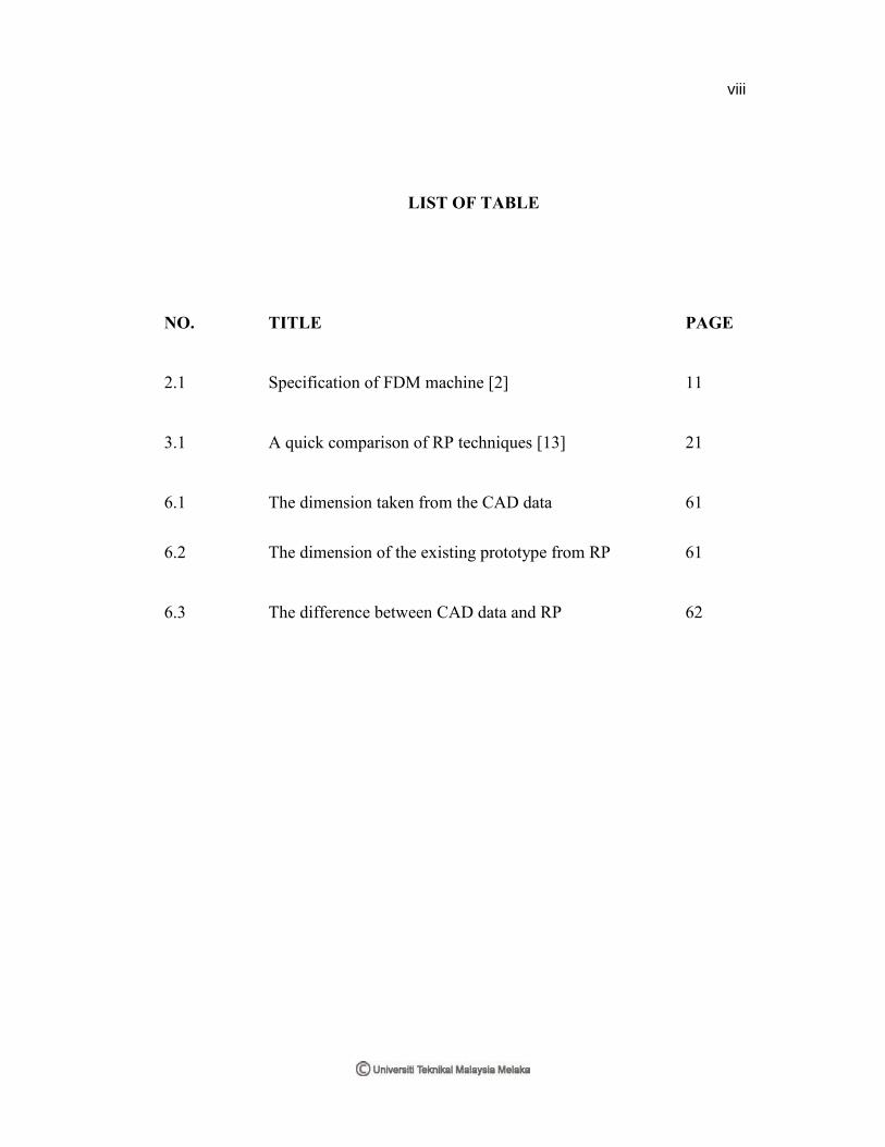
LIST OF TABLE
NO. TITLE PAGE
2.1 Specification of FDM machine [2] 11
3.1 A quick comparison of RP techniques [13] 21
6.1 The dimension taken from the CAD data 61
6.2 The dimension of the existing prototype from RP 61
6.3 The difference between CAD data and RP 62
viii

LIST OF FIGURE
NO. TITLE PAGE
1.1 Flow chart for PSM1 3
1.2 Outline of the project 4
2.1 FDM Prodigy Plus [2] 8
2.2 FDM Vantage [2] 9
2.3 FDM Titan [2] 9
2.4 FDM Maxum [2] 10
3.1 Schematic of SLA process [3] 18
3.2 FDM machine process [12] 19
3.3 Three Dimensional Printing (3DP) process [12] 20
3.4 Schematic diagram of RP process chain [13] 22
3.5 Schematic diagram of triangle tessellation of 24
STL file [13]
ix

NO. TITLE PAGE
3.6 Stair-stepping [13] 26
3.7 An application of an RP model for Surgical 27
Planning in Orthopaedic Surgery [14]
3.8 An application of an RP model for Lincoln 27
new wheel [15]
4.1 Example of RTV Silicone Rubber Mould [19] 30
4.2 Schematic of RTV Silicone Rubber Mould 31
Process [20]
5.1 Method flow 34
5.2 Design test model for the normal part 36
5.3 Design test model for the complicated part 37
5.4 The gear knob body 38
5.5 The insert part 38
5.6 The test part 39
5.7 Transferring CAD data to STL file 40
5.8 The sequence process using Magics RP software 41
x

NO. TITLE PAGE
5.9 The properties of the part 42
5.10 All parts are nested into the same platform 43
5.11 All parts are merged 43
5.12 All parts are become same in colour 44
5.13 Sequence process of Insight Software 44
5.14 Opening the merge part in the Insight software 44
5.15 Checking the plane 45
5.16 Model processing 45
5.17 Clicking the Build button 46
5.18 Estimate builds time 46
5.19 The operation in Prodigy Plus 47
5.20 The display on Prodigy Plus 47
5.21 Removing support from parts 48
5.22 Part immerse in the WaterWorks Solution 49
5.23 Stratasys WaterWorks Solution 49
xi
NO. TITLE PAGE
5.24 Washing the removed part 50
5.25 Sanding the part’s surface 50
5.26 Painting the part using spray paint and drying the paint 51
inside the oven
5.27 The painted parts 51
5.28 Sequence of fabricating RTV silicone rubber mould 52
5.29 Master models are embedded in modeling clay 52
5.30 Making wavelike shapes on the modeling clay 53
5.31 Taping the plywood with brown tape 53
5.32 The moulding frame glued with the glue gun 54
5.33 Weighing the components 54
5.34 Mixing the silicone 55
5.35 Primary de-gassing of the silicone 55
5.36 Filling in the silicone 56
5.37 Secondary de-gassing of the silicone 56
xii

NO. TITLE PAGE
5.38 Hardening the silicone mould in the oven 57
5.39 Silicone gate, first half of the mould 57
5.40 Making the second half of the mould 58
5.41 The silicone mould is ready for the first cast 58
6.1 General flow of the project 59
6.2 Dimension from CATIA 61
6.3 The material not fills completely 62
6.4 Failure on the thread part 63
6.5 Measuring the moulding frame 64
xiii

GLOSSARY
SYMBOL DEFINITION
3DP Three Dimensional Printing
ABS Acrylonitrile Butadiene Styrene
BASS Break Away Support System
CAD Computer Aided Design
FDM Fused Deposition Modeling
FKM Fakulti Kejuruteraan Mekanikal
PPSF Polyphenylsulfone
RP Rapid Prototyping
RT Rapid Tooling
RTV Room Temperature Vulcanization
SLA Steriolithography Apparatus
STL Standard Triangulation Language
UTeM Universiti Teknikal Malaysia Melaka
UV Ultraviolet
xiv

CHAPTER I
INTRODUCTION TO THE PROJECT
1.1 Project Background
‘Projek Sarjana Muda’ (PSM) is a must to the final year students in UTeM in
order to complete their degree in the engineering course. PSM allows the students to do
research and project based on the subjects learned in the classes, the experience they get
during the industrial training and any cases related with the project.
This project focuses on how to fabricate the silicon rubber mould using rapid
prototyping (RP) and rapid tooling (RT) techniques. In this project, two parts will be
tested where the first part will be a normal part of geometry while the other part is a
complicated part of geometry. The project will start from literature search, followed by
Computer Aided Design (CAD) software to design test models, rapid prototyping by
creating the master parts using Fused Deposition Modeling (FDM) machine and then
rapid tooling to produce the mould using vacuum casting machine.
Since the vacuum casting machine is still new in the rapid prototyping
laboratory, the project was chosen to expose the application of this machine to all the
FKM’s student here. This project also describes the advantages and disadvantages of this
vacuum casting machine.
1

1.2 Objective of Project
The objective of this project is to carry out the study on fabrication methods of
various part geometries using silicone rubber mould for vacuum casting machine.
1.3 Scopes of Project
The scopes of project are as follow:
i. To study about Rapid Tooling and Rapid Prototyping
ii. To design master parts that will be use to fabricate silicone rubber mould
for vacuum casting machine
iii. To study the industries that using vacuum casting
iv. To study the application of vacuum casting
v. To study the advantages and disadvantages of vacuum casting
vi. To do test models for normal and complicated designs
vii. To understand how to use the Fused Deposition Modeling Machine
(FDM) and Prodigy Plus system
viii. To produce the detailed drawings
ix. To fabricate the master parts
x. To fabricate the silicone rubber mould for vacuum casting machine using
the master parts
2
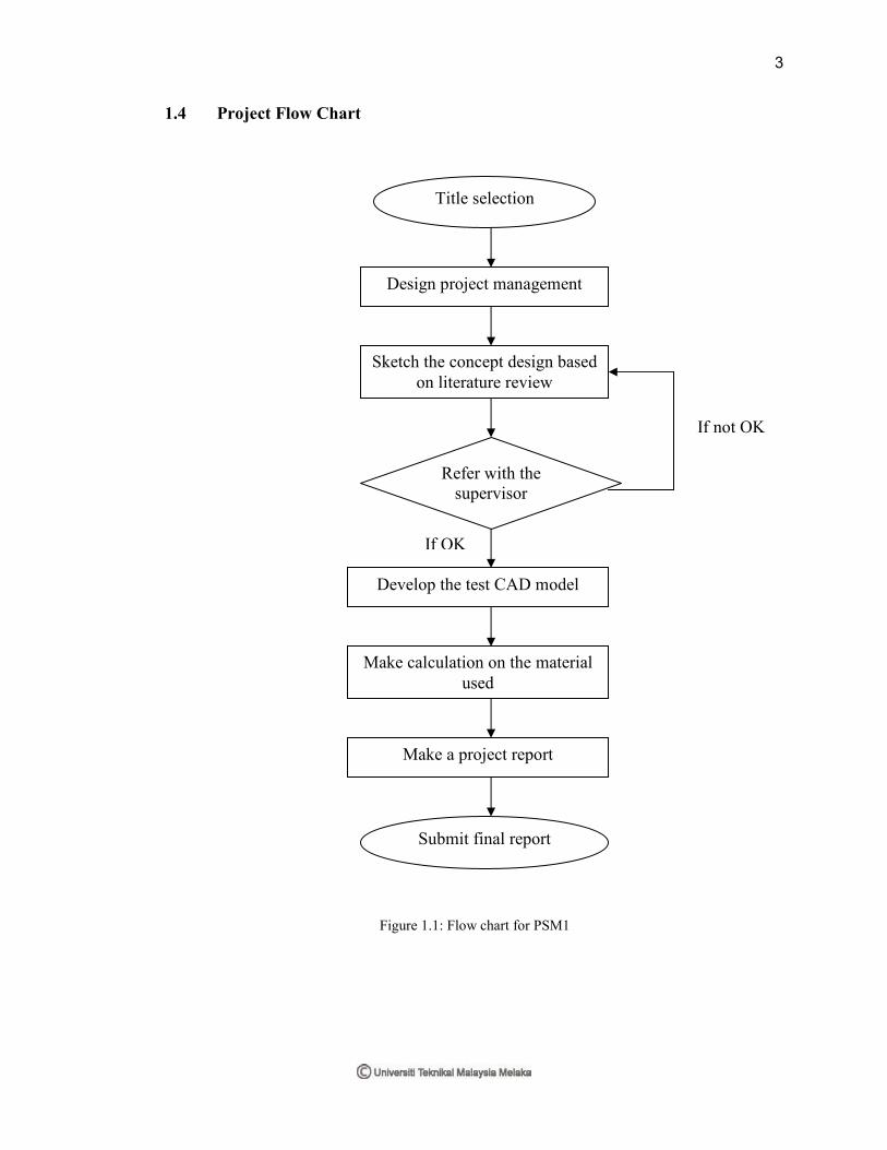
1.4 Project Flow Chart
Figure 1.1: Flow chart for PSM1
Title selection
Design project management
Sketch the concept design based
on literature review
Refer with the
supervisor
Make calculation on the material
used
Develop the test CAD model
Make a project report
Submit final report
If OK
If not OK
3
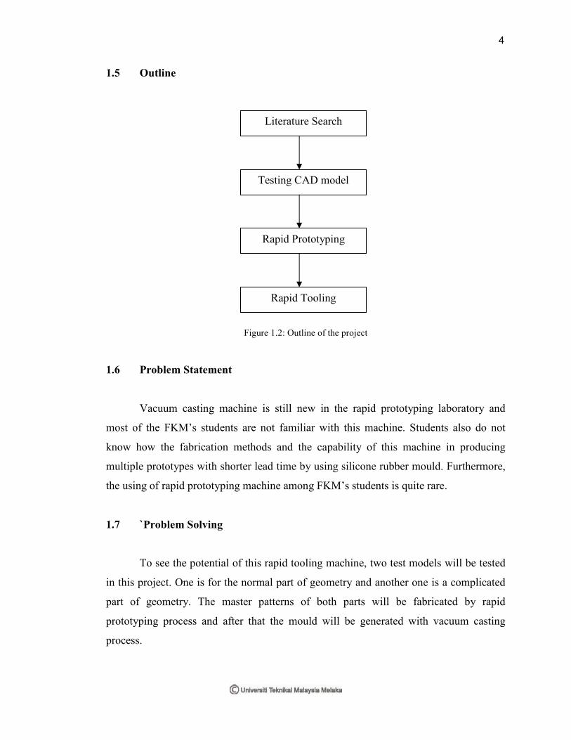
1.5 Outline
Figure 1.2: Outline of the project
1.6 Problem Statement
Vacuum casting machine is still new in the rapid prototyping laboratory and
most of the FKM’s students are not familiar with this machine. Students also do not
know how the fabrication methods and the capability of this machine in producing
multiple prototypes with shorter lead time by using silicone rubber mould. Furthermore,
the using of rapid prototyping machine among FKM’s students is quite rare.
1.7 `Problem Solving
To see the potential of this rapid tooling machine, two test models will be tested
in this project. One is for the normal part of geometry and another one is a complicated
part of geometry. The master patterns of both parts will be fabricated by rapid
prototyping process and after that the mould will be generated with vacuum casting
process.
Literature Search
Testing CAD model
Rapid Prototyping
Rapid Tooling
4
CHAPTER II
LITERATURE SEARCH
2.1 Introduction of Literature Search
Literature search is the most important step to gain as much information as
possible with regard to the discussed topics. It can be done by searching the information
from the internets, journals, books and other sources such as attending any seminars or
courses offered outside or inside the university.
According to this project title, the literature search will focus more on how to
fabricate a silicone rubber mould for vacuum casting machine for any parts with normal
and complicated designs. The parts have been chosen are a model of an ashtray and a
gear knob.
The first step to do is making a master pattern of the each part by using the RP
technique. There are many types of RP machines such as Stereolithography Apparatus
(SLA), Fused Deposition Modeling (FDM) and Three-dimensional Printing (3DP). The
RP machine used in rapid prototyping lab here is FDM Prodigy Plus made by Stratysis
from United State of America (USA). In order to make the master pattern, creation of a
Computer Aided Design (CAD) model should be done first using any CAD software.
5

After completing the master pattern, the process will turn to the rapid tooling
where the state method for this project is vacuum casting. From this method, the master
pattern will be used to make a silicone rubber mould. The mould will be made using the
Room Temperature Vulcanization (RTV) silicone rubber molding process.
This chapter includes the overview of FDM, vacuum casting machine and
Computer Aided Design (CAD) while rapid prototyping and rapid tooling will be
discussed in the next chapter.
6


