36
FC 4-722-01F 2 July 2007 Change 1, 1 May 2013 FACILITIES CRITERIA (FC) AIR FORCE DINING FACILITIES APPROVED FOR PUBLIC RELEASE; DISTRIBUTION IS UNLIMITED

FC 4-722-01F 2 July 2007
Change 1, 1 May 2013
FACILITIES CRITERIA (FC)
AIR FORCE DINING FACILITIES
APPROVED FOR PUBLIC RELEASE; DISTRIBUTION IS UNLIMITED
FC 4-722-01F 2 July 2007
Change 1, 1 May 2013
UNIFIED FACILITIES CRITERIA PROGRAM
FACILITIES CRITERIA AIR FORCE
DINING FACILITIES
Any copyrighted material included in this FC is identified at its point of use. Use of the copyrighted material apart from this FC must have the permission of the copyright holder. U.S. ARMY CORPS OF ENGINEERS NAVAL FACILITIES ENGINEERING COMMAND AIR FORCE CIVIL ENGINEER CENTER (Preparing Activity) Record of Changes (changes are indicated by \1\ ... /1/) Change No. Date Location 1 1 May 2013 Revised throughout to change from a UFC to an FC
for Air Force Requirements only, and to remove Army and Navy-Marine Corps Requirements. Navy-Marine/Corps requirements will be provided in an FC with same number and an “N.” Army requirements will be provided by USACE Center of Standardization. Added Chapter 1, Paragraph entitled, “General Building Requirements”.
This Facilities Criteria (FC) supersedes UFC 4-722-01, dated 2 July 2007.

FC 4-722-01F 2 July 2007
Change 1, 1 May 2013
FOREWORD Facilities Criteria (FC) provide functional requirements (i.e., defined by users and operational needs of a particular facility type) for specific DoD Component(s), and are intended for use with unified technical requirements published in DoD Unified Facilities Criteria (UFC). FC are applicable only to the DoD Component(s) indicated in the title, and do not represent unified DoD requirements. Differences in functional requirements between DoD Components may exist due to differences in policies and operational needs. All construction outside of the United States is also governed by Status of Forces Agreements (SOFA), Host Nation Funded Construction Agreements (HNFA), and in some instances, Bilateral Infrastructure Agreements (BIA.) Therefore, the acquisition team must ensure compliance with the most stringent of the UFC (replace w/ FC), the SOFA, the HNFA, and the BIA, as applicable. Because FC are coordinated with unified DoD technical requirements, they form an element of the DoD UFC system applicable to specific facility types. The UFC system is prescribed by MIL-STD 3007 and provides planning, design, construction, sustainment, restoration, and modernization criteria, and applicable to the Military Departments, Defense Agencies, and the DoD Field Activities. The UFC System also includes technical requirements and functional requirements for specific facility types, both published as UFC documents and FC documents. FC are living documents and will be periodically reviewed, updated, and made available to users as part of the Services’ responsibility for providing criteria for military construction. Headquarters, U.S. Army Corps of Engineers (HQUSACE), Naval Facilities Engineering Command (NAVFAC), and the Air Force Civil Engineer Center (AFCEC) are responsible for administration of the UFC system. Defense agencies should contact the preparing service for document interpretation and improvements. Technical content is the responsibility of the cognizant DoD working group. Recommended changes with supporting rationale should be sent to the respective service proponent office by the following electronic form: Criteria Change Request. The form is also accessible from the Internet site listed below. FC are effective upon issuance and are distributed only in electronic media from the following source:
• Whole Building Design Guide web site http://dod.wbdg.org/. Refer to UFC 1-200-01, General Building Requirements ,for implementation of new issuances on projects. AUTHORIZED BY:
______________________________________
The Deputy Civil Engineer DCS/Installations & Logistics Department of the Air Force

FC 4-722-01F 2 July 2007
Change 1, 1 May 2013
FACILITIES CRITERIA (FC) REVISION SUMMARY SHEET
Document: FC 4-722-01F, Dining Facilities Superseding: UFC 4-722-01 Dining Facilities, dated 2 July 2007 Description of Changes: The primary intent of this revision was to develop performance-based criteria to facilitate the application of this document to design-build projects. Therefore, the planning section was reworked to outline the facility’s functional spaces and the criteria for each space that drives the planning process. The following key planning factors were identified: Number of personnel served, meal schedule and duration, serving methodologies, and serving capacity/turnover rate. The intent is to provide the operational considerations which drive the planning and design of Dining Facilities. Reasons for Changes: The FC has been changed for the following reasons:
• Facilitate the application of this document to design-build projects. • \1\ Correct errors and outdated material and references./1/
Impact: Facility construction costs should be reduced as a result of these changes for the following reasons:
• The performance-based criteria should reduce design-build proposals. Responders will be able to apply industry best-practices and more creativity to their proposals to reduce costs while still meeting the minimum technical design and construction standards outlined in Chapter 3.

FC 4-722-01F 2 July 2007
Change 1, 1 May 2013
i
TABLE OF CONTENTS CHAPTER 1 INTRODUCTION ....................................................................................... 1
1-1 SCOPE. ..................................................................................................... 1
1-2 GENERAL BUILDING REQUIREMENTS. ................................................ 1
1-3 DISTRIBUTION OF RESPONSIBILITIES. ................................................ 1
1-4 COORDINATION. ...................................................................................... 1
1-4.1 Design Professionals. ............................................................................ 1
1-4.2 Acquisition Methodology. ....................................................................... 1
1-5 SCOPE OF FACILITY. .............................................................................. 2
CHAPTER 2 PLANNING AND DESIGN ISSUES ........................................................... 3
2-1 FOOD SERVICE PLANNING DETERMINATIONS. .................................. 3
2-1.1 Number of Personnel to be Served. ....................................................... 3
2-1.2 Meal Schedule and Duration. ................................................................. 3
2-1.3 Payment. ................................................................................................ 3
2-1.4 Food Delivery and Eating Methodology. ................................................ 3
2-1.5 Menu. ..................................................................................................... 3
2-1.6 Staffing................................................................................................... 4
2-1.7 Bussing. ................................................................................................. 4
2-1.8 Other Facility Functions. ........................................................................ 4
2-2 FUNCTIONAL SPACES. ........................................................................... 4
2-2.1 Entrance Lobby. ..................................................................................... 4
2-2.2 Queue. ................................................................................................... 4
2-2.3 Serving Area. ......................................................................................... 4
2-2.4 Cashier Station. ..................................................................................... 5
2-2.5 Dining Area. ........................................................................................... 5

FC 4-722-01F 2 July 2007
Change 1, 1 May 2013
ii
2-2.6 Public Toilets. ........................................................................................ 5
2-2.7 Dish/Pot-Washing. ................................................................................. 5
2-2.8 Kitchen and Preparation Areas. ............................................................. 5
2-2.9 Storage. ................................................................................................. 5
2-2.10 Loading Dock. ........................................................................................ 6
2-2.11 Support Areas. ....................................................................................... 6
2-2.12 Other Facility Functions. ........................................................................ 6
2-2.13 Building Services Areas. ........................................................................ 6
2-2.14 Trash & Garbage Removal and Recycling. ............................................ 6
2-3 SIZE OF FACILITIES. ............................................................................... 6
2-4 SPACE PROGRAMS. ............................................................................... 6
2-5 BUILDING SITE. ....................................................................................... 6
2-5.1 Location. ................................................................................................ 6
2-5.2 Natural Light. ......................................................................................... 7
2-5.3 Separate Service Functions. .................................................................. 7
2-5.4 Patron Circulation. ................................................................................. 7
2-5.5 Outdoor Dining Area. ............................................................................. 7
2-6 BUILDING LAYOUT. ................................................................................. 7
2-6.1 Flow Schematic. .................................................................................... 7
2-6.2 Functional Planning. .............................................................................. 8
2-6.3 Separate the Dining Area....................................................................... 8
2-7 BUILDING DESIGN. .................................................................................. 9
2-7.1 Design for Flexibility. .............................................................................. 9
2-7.2 Aesthetics and Visual Image. ................................................................. 9
2-7.3 Glazing................................................................................................... 9

FC 4-722-01F 2 July 2007
Change 1, 1 May 2013
iii
2-7.4 Quality Work Environment. .................................................................... 9
2-7.5 Design for Durability and Maintainability. ............................................. 10
CHAPTER 3 CODES AND DESIGN STANDARDS ..................................................... 11
3-1 GENERAL. .............................................................................................. 11
3-1.1 Food Code. .......................................................................................... 11
3-1.2 Design for OCONUS Installations. ....................................................... 11
3-2 SITE WORK. ........................................................................................... 11
3-2.1 Landscape. .......................................................................................... 11
3-2.2 Parking, Access Drives, and Other Site Features. ............................... 11
3-3 ARCHITECTURE AND INTERIOR DESIGN. .......................................... 11
3-3.1 General. ............................................................................................... 11
3-3.2 Coordination. ....................................................................................... 12
3-4 ELECTRICAL DESIGN. .......................................................................... 12
3-4.1 Local Conditions. ................................................................................. 12
3-4.2 Lighting. ............................................................................................... 12
3-4.3 Special Systems. ................................................................................. 13
3-4.4 Lightning and Cathodic Protection. ...................................................... 13
3-4.5 Coordination. ....................................................................................... 13
3-5 COMMUNICATIONS AND COMPUTER SYSTEMS. .............................. 14
3-5.1 Telephones. ......................................................................................... 14
3-5.2 Electronic Cash Registers and Computers. ......................................... 14
3-5.3 CCTV and Cable TV. ........................................................................... 14
3-6 HEATING, VENTILATION, AND AIR CONDITIONING (HVAC) DESIGN................................................................................................................ 14
3-6.1 Coordination. ....................................................................................... 14

FC 4-722-01F 2 July 2007
Change 1, 1 May 2013
iv
3-6.2 Heat Recovery Equipment. .................................................................. 15
3-6.3 Controls. .............................................................................................. 15
3-7 PLUMBING DESIGN. .............................................................................. 15
3-7.1 Waste Systems. ................................................................................... 15
3-7.2 Water Supply Systems. ....................................................................... 15
3-7.3 Coordination. ....................................................................................... 16
3-8 EQUIPMENT. .......................................................................................... 16
3-8.1 Walk-In Refrigeration/Freezer. ............................................................. 17
APPENDIX A REFERENCES ..................................................................................... 19
APPENDIX B BEST PRACTICES .............................................................................. 21
B-1 INTRODUCTION. ................................................................................ 21
B-2 GENERAL BUILDING DESIGN. .......................................................... 21
B-2.1 Interior Materials and Finishes. ............................................................ 21
B-2.2 Acoustics. ............................................................................................ 23
B-3 QUEUE. ............................................................................................... 24
B-4 DINING AREA. .................................................................................... 24
B-5 SERVERY. ........................................................................................... 24
B-6 FOOD SERVICE AREAS. .................................................................... 24
B-7 FOOD SERVICE EQUIPMENT. .......................................................... 25
B-7.1 Vibration. .............................................................................................. 25
B-7.2 Utilities. ................................................................................................ 25
B-8 STAFF FACILITIES. ............................................................................ 26
B-8.1 Staff Toilets. ......................................................................................... 26
B-8.2 Staff Lockers. ....................................................................................... 26

FC 4-722-01F 2 July 2007
Change 1, 1 May 2013
v
FIGURES FIGURE 2-1. DINING FACILITY FLOW SCHEMATIC ............................................... 8
TABLES
TABLE B-1. ARCHITECTURAL FINISHES............................................................... 22
TABLE B-2. STAFF LOCKER COUNT ..................................................................... 26

FC 4-722-01F 2 July 2007
Change 1, 1 May 2013
vi
This Page Intentionally Left Blank

FC 4-722-01F 2 July 2007
Change 1, 1 May 2013
1
CHAPTER 1 INTRODUCTION
1-1 SCOPE.
This Facilities Criteria (FC) presents facility operation, programming, and sustainability information to guide the design and construction criteria for all Air Force enlisted dining facilities for both outside and inside the continental United States. Emphasis is placed on the design of functional and pleasant food service facilities that help attract and retain service personnel. This FC applies to both new construction and renovation and modernization projects.
1-2 GENERAL BUILDING REQUIREMENTS.
\1\ Comply with UFC 1-200-01, "General Building Requirements.” UFC 1-200-01 provides applicability of model building codes and government-unique criteria for typical design disciplines and building systems, as well as for accessibility, antiterrorism, security, sustainability, and safety. Use this FC in addition to UFC 1-200-01 and the UFCs and government criteria referenced therein./1/
1-3 DISTRIBUTION OF RESPONSIBILITIES.
\1\ /1/
There are three participants in the development of Air Force facility design. First, the local installation Civil Engineer identifies the need for a new, modernized, or enlarged dining facility and initiates the project development process. Second, an Air Force project manager is designated to manage design and construction. Third, the Air Force Services Agency sets the standards for all Air Force food service operations and determines the facilities and equipment required to perform the operations.
Direct questions regarding Air Force projects to \1\ HQ AFCEC/TDB. /1/
\1\ /1/
1-4 COORDINATION.
Prior to project development, coordinate the design team composition and facility requirements with the contact noted in the paragraph entitled, “General Building Requirements” and confirm the acquisition methodology.
1-4.1 Design Professionals.
The design team of record for Dining Facilities shall include a food service consultant that is qualified as a member of Foodservice Consultants Society International or equal. The design team should coordinate with Air Force user representatives and construction staff.
1-4.2 Acquisition Methodology.
FC 4-722-01F 2 July 2007
Change 1, 1 May 2013
2
There are two primary acquisition methodologies for Government construction: design-bid-build and design-build. Service personnel involved with project development should understand the acquisition methodology as it affects how and when they can influence the resulting facility design.
1-4.2.1 Design-Bid-Build.
The design-bid-build acquisition methodology is characterized by separation between the designer of record and the construction contractor. The Government contracts with an architect or engineer to design the facility and separately contracts with a contractor for construction. Service personnel have the opportunity to interface with the designer of record and influence the design at several predefined points in the design process.
1-4.2.2 Design-Build.
The design-build acquisition methodology is characterized by the combination of design and construction services under one contract. The Government contracts with one entity to prepare the design and to construct the facility based on the requirements outlined in a request for proposal (RFP). Service personnel have the opportunity to influence the design during the development of the RFP and during the design-build contractor selection process.
1-5 SCOPE OF FACILITY.
Dining facility functional design is driven by the payment style, food delivery and eating methodologies, and any additional functions accommodated in the specific facility. These functions and how they drive the design of the facility are described in detail in the paragraph entitled, “Food Service Planning Determinations”.

FC 4-722-01F 2 July 2007
Change 1, 1 May 2013
3
CHAPTER 2 PLANNING AND DESIGN ISSUES
2-1 FOOD SERVICE PLANNING DETERMINATIONS.
Planning the size and layout of dining facilities depends upon the following determinations.
2-1.1 Number of Personnel to be Served.
The number of personnel to be served drives the overall size of the facility (also see the paragraph entitled, “Functional Spaces”) per \1\ /1/ Air Force Manual AFMAN 32-1084, “Facility Requirements”.
2-1.2 Meal Schedule and Duration.
The meal schedule and duration affects both the sizing and layout of the facility. Meal schedule may vary by Service, region, and Installation. The specific meal schedule shall be determined as part of the planning process. \1\ /1/
2-1.3 Payment.
The payment style affects the layout of the facility.
• Cafeteria style. Patrons pay a set meal price upfront and chose from predetermined options.
• A la Carte. Patrons pick up individual menu items and pay only for the items selected.
2-1.4 Food Delivery and Eating Methodology.
The food delivery and eating methodologies affect the size and layout of the facility. Dining facilities may accommodate more than one of the following methodologies:
• Serving Line or Station. Patrons choose from predetermined options off of serving lines or stations such as hot bar line, salad bar, deli bar, pizza bar, taco bar, etc. Food may be packaged for consumption in the facility or for takeout.
• Short order. Patrons order items for custom preparation. Food may be packaged for consumption in the facility or for takeout.
• Takeout/Meal Replacement. Patrons chose from assorted prewrapped and prepackaged items that may range from hamburgers and pizza to full meals.
2-1.5 Menu.

FC 4-722-01F 2 July 2007
Change 1, 1 May 2013
4
Menu options, nutritional guidelines, and the required variety shall be determined prior to design. These will be used to determine the needed preparation and serving equipment and storage.
2-1.6 Staffing.
Staffing requirements shall be determined prior to design and will be used to size the administrative areas, staff lockers, and toilets.
2-1.7 Bussing.
The choice of contract/staff bussing or patron self-bussing is the option of the local command. All facilities shall be designed to accommodate both modes of bussing, and this affects the facility layout. Bussing carts should be screened from view of the dining area.
2-1.8 Other Facility Functions.
The dining facility may accommodate one or more of the following additional functions:
• Field Feeding/Vat Chow. Dining facility prepares group meals for field consumption. This function includes storage of field preparation and serving equipment.
• Flight Kitchens and Box/Bag Meals. Dining facility prepares individual meals for field consumption.
• Recreation Chow. Dining facility prepares special event group meals for consumption outside the facility.
2-2 FUNCTIONAL SPACES.
The food service planning determinations along with other basic building design and operation determinations establish the size, layout, and design of the facility functional spaces.
2-2.1 Entrance Lobby.
The entrance lobby is the main entrance to the facility, and the size is determined by the number of personnel to be served. Provide a canopy or enclosure for patrons who arrive in advance of the opening of the facility. In extreme weather areas, this function can be accomplished in the form of a vestibule.
2-2.2 Queue.
The queue is the space between the entrance lobby and the serving area and is determined by the serving capacity and the serving methodology.
2-2.3 Serving Area.

FC 4-722-01F 2 July 2007
Change 1, 1 May 2013
5
The serving area accommodates ordering and delivery of food to patrons and is determined by the food delivery methodology and the payment style.
2-2.4 Cashier Station.
The cashier station accommodates patron payment and is determined by the food delivery methodology and the payment style. Payment options (cash, credit, Smart™ cards) will be determined prior to design.
2-2.5 Dining Area.
The dining area accommodates patron eating and relaxation. It is determined by the number of personnel to be served, the meal schedule and duration, and the food delivery methodology as expressed by turnover/serving capacity and seating capacity.
2-2.5.1 Turnover/Serving Capacity.
Turnover is the number of times a dining area seat is occupied during a given period. Turnover drives the serving capacity, which is the number of patrons served within the set meal duration. The serving capacity is used to size the functional elements of the Dining Facility to ensure that the required number of patrons can be served in the meal duration. The serving capacity shall be determined prior to design.
2-2.5.2 Seating Capacity.
Seating capacity is determined by considering the required serving capacity and the serving methodology. The seating capacity is used to size the dining area of the facility. \1\ /1/
2-2.6 Public Toilets.
The public toilets are determined by the number of personnel to be served.
2-2.7 Dish/Pot-Washing.
The dish- and pot-washing areas are determined by the number of personnel to be served, bussing considerations, the food delivery methodology, and the menu.
2-2.8 Kitchen and Preparation Areas.
The kitchen and all food preparation areas are determined by the number of personnel to be served, the food delivery methodology, and the menu.
2-2.9 Storage.
Storage areas accommodate stocks of subsistence (consumables) and nonsubsistence; e.g., tableware, cleaning supplies. The areas are determined by analysis of the menu, the number of personnel to be served, and the defined delivery cycles.
FC 4-722-01F 2 July 2007
Change 1, 1 May 2013
6
2-2.10 Loading Dock.
The loading dock accommodates material transfer in and out of the facility and shall be coordinated with storage requirements.
2-2.11 Support Areas.
Support areas accommodate staff needs such as offices and administrative tasks, toilets, lockers, and janitor closets. The areas are determined by the staffing requirements.
2-2.12 Other Functions.
These spaces will be determined by the specific facility functions required as described in the paragraph entitled, “Other Facility Functions.”
2-2.13 Building Services Areas.
These spaces accommodate building services such as mechanical, electrical, and communications.
2-2.14 Trash & Garbage Removal and Recycling.
Garbage removal and recycling systems will be determined prior to design.
2-3 SIZE OF FACILITIES.
\1\ Gross allowable area is defined by guidance provided in Air Force Manual, AFMAN 32-1084, “Facility Requirements”. /1/
2-4 SPACE PROGRAMS.
\1\
The Air Force provides design guidelines for its facilities.
/1/
2-5 BUILDING SITE.
This facility will be a focal point of the local community. It should be an open and inviting gathering place for service personnel. Consider the following factors in the site selection and design.
2-5.1 Location.
Locate the facility along the pedestrian paths to the existing barracks/dormitories and centralized support services. To accommodate patron access, consider the relationships to existing vehicular and pedestrian circulation patterns, bike trails, and

FC 4-722-01F 2 July 2007
Change 1, 1 May 2013
7
bus stops. Consider providing a Porte Cochere for shuttle busses. Provide adequate parking as close to the facility as possible within antiterrorism (AT) requirements.
2-5.2 Natural Light.
Select a site to maximize the admission of natural light while minimizing heat gain through the glazing. Direct sunlight should not touch the glazing: Consider landscaping to avoid direct sunshine.
2-5.3 Separate Service Functions.
Separate service functions such as loading docks, maintenance yards, trash containers, on-grade mechanical equipment, and staff parking from the rest of the site by architectural screening, landscaping, or grading.
2-5.4 Patron Circulation.
Patrons arrive from many directions. Identify the various access points, both pedestrian and vehicular, and channel circulation to the entrance of the building. Encourage smooth circulation by landscaping and paving complementary to the building. Entry circulation begins as the patron enters the site and continues through the interior of the facility.
2-5.5 Outdoor Dining Area.
Consider providing an outdoor dining area, if the site and climate permits.
2-6 BUILDING LAYOUT.
The building should be laid out to foster efficient flow of people, materials, and work activities. It should also seek to visually and acoustically separate patron functions from food preparation and cleaning functions.
2-6.1 Flow Schematic.
Figure 2-1 schematically illustrates the building layout in terms of major functional areas and displays the flow of people and material. \1\ Also refer to the “Dining Facilities Design Guide”. /1/

FC 4-722-01F 2 July 2007
Change 1, 1 May 2013
8
FIGURE 2-1. DINING FACILITY FLOW SCHEMATIC
2-6.2 Functional Planning.
The relationship among the various storage, preparation, cooking, serving, and cleaning functions must be carefully studied to provide the maximum flow and efficiency. Keep travel distances short and minimize crossover of circulation paths. Maintain open sight lines as possible and utilize mobile food service equipment for flexibility. Provide utility connections for mobile food service equipment. Plan for various serving styles.
2-6.3 Separate the Dining Area.
The dining area represents the conclusion of the patron process of arrival, queuing, identification, serving, and payment. To the extent possible, separate dining patrons from the congestion and movement of arriving and departing patrons. To avoid congestion within the dining facility, patron circulation space at bussing area should be as large as possible.

FC 4-722-01F 2 July 2007
Change 1, 1 May 2013
9
2-7 BUILDING DESIGN.
The planning and budgeting process shall include the following design considerations. Emphasis is placed on the design of functional and pleasant food service facilities that help attract and retain patrons.
2-7.1 Design for Flexibility.
Planners and designers should recognize that future renovations, additions and expansions of the facility are likely.
2-7.2 Aesthetics and Visual Image.
The dining experience represents a break in the patron’s day. Its design should provide a visual respite as well. The designer should provide an aesthetic and visual image in keeping with the recreational functions of the facility.
2-7.2.1 Develop Architectural Character.
Create an appealing environment through interesting plan areas, spatial volumes, and other design elements. If outdoor dining is provided, consider the effect on both the facility layout and design character.
2-7.2.2 Signage.
Develop a comprehensive signage package for the facility that addresses both way-finding and information.
2-7.2.3 Menus.
The main menu board is a focal point of the entry. Individual serving lines and stations will have their own menu, and the design and location of the menu board will depend on the serving methodology.
Design the entrance areas for flexibility to allow a variety of menu designs in terms of accessibility, space, power, and lighting.
2-7.3 Glazing.
The admission of natural light contributes significantly to the energy efficiency of the building and communicates a feeling of well-being and openness. Coordinate glazing design with the lighting design (see the paragraph entitled, “Lighting”).
Direct sunshine on dining patrons can be uncomfortable and distracts from a positive dining experience. In addition to the site issues noted in the paragraph entitled, “Natural Light”, consider overhangs and other building features to preclude direct sunlight on the seating areas.
2-7.4 Quality Work Environment.

FC 4-722-01F 2 July 2007
Change 1, 1 May 2013
10
Ensure quality building systems, adequate employee facilities, easily accessible safety devices, and prevention of entry by vermin and insects. 2-7.5 Design for Durability and Maintainability.
The materials proven to be the most durable are shown in Table B-1 and should be accommodated in the budget. The design should accommodate access for cleaning and maintenance in high-wear areas, including food preparation and dishwashing and pot- and pan-washing areas.
\1\ /1/

FC 4-722-01F 2 July 2007
Change 1, 1 May 2013
11
CHAPTER 3 CODES AND DESIGN STANDARDS
3-1 GENERAL.
Comply with UFC 1-200-01, “General Building Requirements”, which provides guidance for the use of model building codes for design and construction of DoD facilities. Chapter 3 provides additional criteria for the design and construction of dining facilities.
3-1.1 Food Code.
Design facilities to meet U.S. Department of Health and Human Services, Public Health Service, Food and Drug Administration, ”Food Code”, latest edition.
3-1.2 Design for OCONUS Installations.
Specific guidance for construction in OCONUS locations will be the subject of special consideration. The designer shall comply with Host Nation Agreements.
\1\
New construction of OCONUS dining facilities must comply with DoD 4715.05-G, “Overseas Environmental Baseline Guidance Document (OEBGD)”.
/1/
3-2 SITE WORK.
Comply with UFC 2-600-01, “Installation Design”.
3-2.1 Landscape.
Comply with UFC 3-201-02, “Design: Landscape Architecture” and the local Installation landscape standards. Also refer to the “USAF Landscape Design Guide” and any Major Command standards.
3-2.2 Parking, Access Drives, and Other Site Features.
Comply with UFC 3-210-02, “POV Site Circulation and Parking”.
3-3 ARCHITECTURE AND INTERIOR DESIGN.
3-3.1 General.
General guidance for architectural and interior design is provided in the following documents:
\1\
• UFC 3-120-10, “Interior Design”.

FC 4-722-01F 2 July 2007
Change 1, 1 May 2013
12
• AFMAN 32-1008, “Installation Design” and MAJCOM and Installation Architectural Compatibility/Facilities Excellence standards.
/1/ 3-3.2 Coordination.
The following Items require coordination with the architectural design:
• Requirements for floor drains, wall recesses, stub walls, and any pads or piers needed for food service equipment.
• All bumpers, guards, and protective devices.
• The use of special materials such as nonslip quarry tile, noncorrosive ceiling grid, skim coat plaster on Concrete Masonry Unit (CMU) walls, metal acoustic ceilings, plaster ceilings, and smooth face lay-in tile.
• All roof, ceiling, floor, and wall penetrations for ducts, control lines, refrigerant tubing, etc.
• Floor elevation and slope requirements to ensure proper drainage of water in wet areas.
• Doors from the loading dock into kitchen shall be at least 8 feet (2.4 meters) tall in order to accommodate equipment.
3-4 ELECTRICAL DESIGN.
In addition to the criteria established in Chapter 3, “General”, comply with the following in the design of the electrical system:
\1\
• UFC 3-520-01, “Interior Electrical Systems”
• Air Force Manual AFJMAN 32-1083, “Facilities Engineering Electrical Interior Facilities”. AFI 32-1063, “Electric Power Systems”, authorizes an emergency generator for one feeding facility per installation, with MAJCOM having authority to approve additional eating facilities.
/1/ 3-4.1 Local Conditions.
Evaluate local conditions for their impact on facility design and backup power generation requirements.
3-4.2 Lighting.
Provide lighting and control systems throughout the facility in accordance with UFC 3-530-01, “Design: Interior and Exterior Lighting and Controls”.

FC 4-722-01F 2 July 2007
Change 1, 1 May 2013
13
3-4.3 Special Systems.
Prewire for the following:
• Local Area Network for computerized communications, such as food service and payment management system
• Energy monitoring and control system when mandated or economically justifiable
• Public address and intercom systems
• Security systems, alarm systems, and Closed Circuit Television (CCTV) systems
• Cable television for dining areas 3-4.4 Lightning and Cathodic Protection.
Comply with applicable sections of \1\ UFC 3-575-01, “Lightning and Static Electricity Protection Systems”. /1/
3-4.5 Coordination.
The following items require coordination with the electrical design:
• Location of all spot connections for equipment requiring electrical connection.
• All projected power requirements for food service equipment (coordinated with the food service designer as early as possible). In addition to the power characteristics, the type of electrical connection required (plug-in, junction box) for each piece of equipment must be determined.
• Special requirements for equipment, such as overload protection and control panels, located at the equipment being protected.
• Integration of food service equipment with fire suppression system controls.
• Integration of electrical requirements for equipment utility distribution system.
• Location of conduit required for computer and electronic cash register stations.
• Electrical service requirements for all equipment must be as specified in UFGS 11 05 40, “Common Work Results for Foodservice Equipment”.
• Potential future equipment upgrades.
• Floor-mounted flush receptacles and conduit stub-ups are not permitted in the kitchen area or serving line. For safety reasons, ceiling cord reels will be provided in these areas.
FC 4-722-01F 2 July 2007
Change 1, 1 May 2013
14
3-5 COMMUNICATIONS AND COMPUTER SYSTEMS.
General guidance for the design of telephone systems is provided in \1\ UFC 3-580-01, “Telecommunications Building Cabling Systems Planning and Design”. /1/ Guidance pertinent to the design of dining facilities is as follows.
3-5.1 Telephones.
Provide telephones with a page intercom system in coordination with the local command.
3-5.2 Electronic Cash Registers and Computers.
In preparation for future computer systems, provide empty conduit from the array of register terminals to a location in the food service officer's office for linkage to a computer in use by the food service officer. Install telephone receptacles at all register locations.
3-5.3 CCTV and Cable TV.
Wiring, conduit, routing devices, and equipment must be provided by local command and installed as directed.
3-6 HEATING, VENTILATION, AND AIR CONDITIONING (HVAC) DESIGN.
In addition to the criteria established in Chapter 3, “General”, comply with following in the design of the mechanical system:
• UFC 3-400-02, “Design: Engineering Weather Data” provides local climatic design conditions.
• National Fire Protection Association (NFPA) 96, “Ventilation Control & Fire Protection of Commercial Cooking Operation”.
• Underwriters Laboratories (UL) 710, “Exhaust Hoods for Commercial Cooking Equipment”.
3-6.1 Coordination.
The following items require coordination with the HVAC design:
• Location and size of all ventilated equipment such as exhaust hoods, dishwashing equipment, etc.;
• Special requirements for ductwork connecting to equipment such as drip pans and pitched or vented duct work;
• Ventilation of remote refrigeration condensers; and

FC 4-722-01F 2 July 2007
Change 1, 1 May 2013
15
• Balance of air supply systems so cooking and waste areas are under negative pressure, ensuring that odors are not carried into public areas.
3-6.2 Heat Recovery Equipment. Economic analysis of heat recovery equipment, particularly from ventilation, cold storage, and central HVAC refrigeration, must be per the \1\ “Life Cycle" guideline, AFH 32-1089, “Economic Analysis Guidance Manual”. /1/
3-6.3 Controls.
Specify direct digital control (DDC) system per UFGS 23 09 23.13 20, “BACnet Direct Digital Control Systems for HVAC” or UFGS 23 09 23, “Lonworks Direct Digital Control for HVAC and Other Building Control Systems”. Coordinate DDC specification to ensure proper interface to existing or planned base-wide DDC/EMCS system.
3-7 PLUMBING DESIGN.
In addition to the criteria established in Chapter 3, “General”, \1\ comply with Air Force Handbook AFI 32-1066, “Backflow Prevention Program”, in the design of the plumbing system: /1/
3-7.1 Waste Systems.
Give special consideration to the following:
• Grease traps and other interceptors shall be easily accessible for cleaning.
• Local jurisdiction or waste management program will determine the type of waste permitted from food grinders and waste pulping system.
• Apply an air gap of two pipe diameters to all kitchen equipment drains not having other backflow protection. Navy projects also use Cross-Connection Control and Backflow Prevention Program Implementation.
• Coordinate floor sinks of adequate size and non–splash receptor design with drained equipment requirements. Prime floor drains are not used as indirect waste receptors or provided with deep seal traps.
• Avoid locating waste piping above kitchen and storage area.
• Coordinate drain requirements for HVAC, cold storage refrigeration equipment, and the can wash.
3-7.2 Water Supply Systems.
Give special consideration to the following domestic water requirements:
• Specialized food service equipment needs such as hard/soft water and pressure.
FC 4-722-01F 2 July 2007
Change 1, 1 May 2013
16
• Provide high-temperature water supply for the dishwasher, pot and pan wash, can wash, and field feeding area (if provided).
• Diversity factors for water heating based on food service equipment usage. Dining facilities may require two or more different hot water temperatures zones. Public and employee handwashing sinks require either temperature-limiting devices or different incoming hot water temperature than food equipment.
• Hot water storage and recirculation. Note: where limited flow fixtures are required, piping and recirculation system adjustments may be required to ensure hot water at fixture.
• Backflow protection is required on all water connections, including connections to beverage machines that may include internal backflow prevention, in accordance with the references provided in this FC.
3-7.3 Coordination.
Items requiring coordination with the plumbing design are as follows:
• Food service designer determines the locations and specifications for all food service equipment (fixed and relocatable). Food service equipment layout and specifications must be coordinated with the facility mechanical designer for coordination of facility plumbing design.
• The locations of all water, waste, steam and steam condensate, refrigeration condensate, floor drains, and gas lines. These lines must be concealed but readily accessible for maintenance.
• Unavoidable exposed vents for island or freestanding equipment must be coordinated with the architect for enclosure.
• All special or custom-made equipment must be installed by the plumbing contractor. Design and location of required grease traps will require coordination among the mechanical, plumbing, architectural, and, possibly, the structural designers.
• If under-floor conduits are used for routing of beverage system, ensure that they are sealed conduits with cleanout.
• Provide floor drains and hose bibb in beverage storage area.
• Plumbing to the automatic wash-down system for exhaust hoods.
• Special requirements for plumbing connections to utility distribution systems.
• Flexible connections must be stainless steel, 300 series finish.
• Provide easy access to waste traps and collectors for cleaning. 3-8 EQUIPMENT.

FC 4-722-01F 2 July 2007
Change 1, 1 May 2013
17
3-8.1 Walk-In Refrigeration/Freezer.
\1\
Use United States Army document, TB MED 530, “Food Service Sanitation”.
/1/
Provide a window in the door of walk-in refrigerators and freezers to permit views of anyone entering or exiting.

FC 4-722-01F 2 July 2007
Change 1, 1 May 2013
18
This page intentionally left blank
FC 4-722-01F 2 July 2007
Change 1, 1 May 2013
19
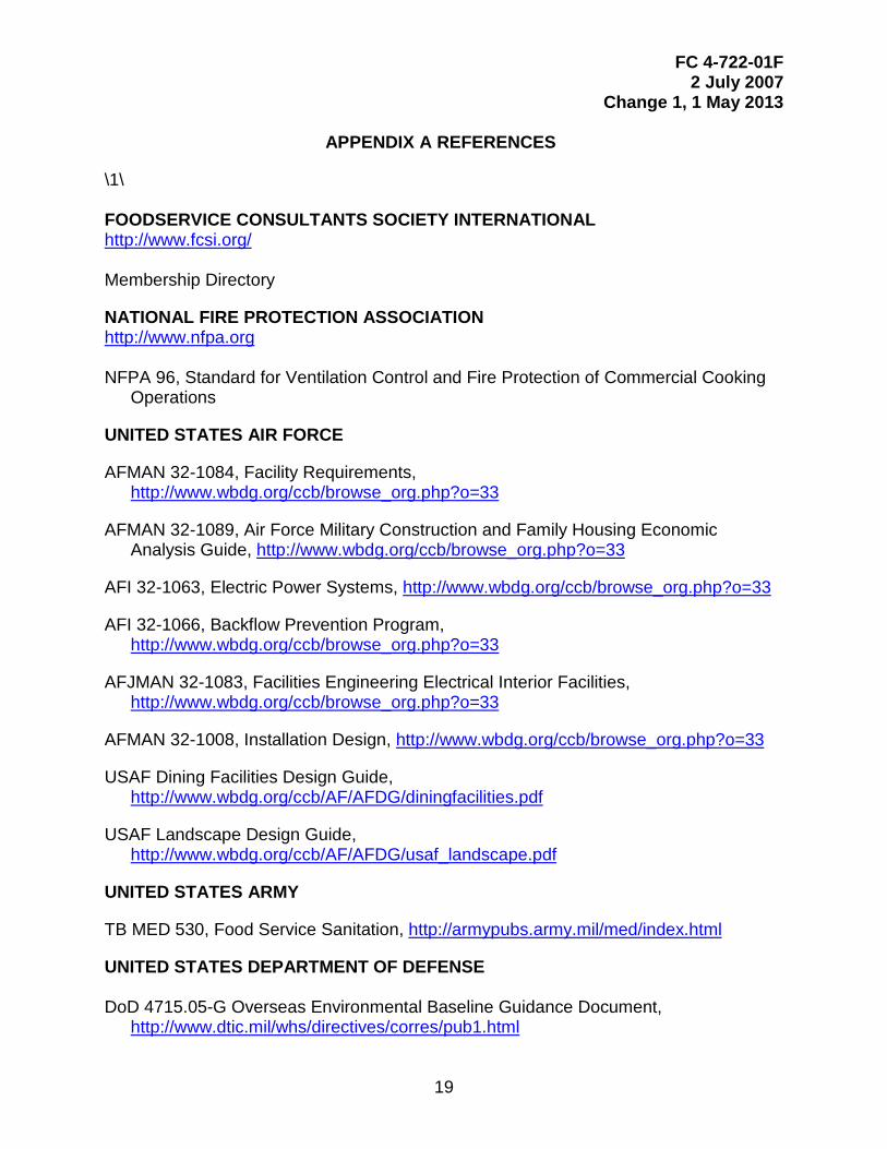
APPENDIX A REFERENCES
\1\ FOODSERVICE CONSULTANTS SOCIETY INTERNATIONAL http://www.fcsi.org/ Membership Directory
NATIONAL FIRE PROTECTION ASSOCIATION http://www.nfpa.org NFPA 96, Standard for Ventilation Control and Fire Protection of Commercial Cooking
Operations
UNITED STATES AIR FORCE
AFMAN 32-1084, Facility Requirements, http://www.wbdg.org/ccb/browse_org.php?o=33
AFMAN 32-1089, Air Force Military Construction and Family Housing Economic Analysis Guide, http://www.wbdg.org/ccb/browse_org.php?o=33
AFI 32-1063, Electric Power Systems, http://www.wbdg.org/ccb/browse_org.php?o=33
AFI 32-1066, Backflow Prevention Program, http://www.wbdg.org/ccb/browse_org.php?o=33
AFJMAN 32-1083, Facilities Engineering Electrical Interior Facilities, http://www.wbdg.org/ccb/browse_org.php?o=33
AFMAN 32-1008, Installation Design, http://www.wbdg.org/ccb/browse_org.php?o=33
USAF Dining Facilities Design Guide, http://www.wbdg.org/ccb/AF/AFDG/diningfacilities.pdf
USAF Landscape Design Guide, http://www.wbdg.org/ccb/AF/AFDG/usaf_landscape.pdf
UNITED STATES ARMY
TB MED 530, Food Service Sanitation, http://armypubs.army.mil/med/index.html
UNITED STATES DEPARTMENT OF DEFENSE DoD 4715.05-G Overseas Environmental Baseline Guidance Document,
http://www.dtic.mil/whs/directives/corres/pub1.html

FC 4-722-01F 2 July 2007
Change 1, 1 May 2013
20
UNITED STATES DEPARTMENT OF DEFENSE, UNIFIED FACILITIES CRITERIA PROGRAM http://dod.wbdg.org UFC 1-200-01, General Building Requirements
UFC 2-600-01, Installation Design
UFC 3-120-10, Interior Design
UFC 3-201-02, Landscape Architecture
UFC 3-210-02, POV Site Circulation and Parking
UFC 3-400-02, Design: Engineering Weather Data
UFC 3-520-01, Interior Electrical Systems
UFC 3-530-01, Design: Interior and Exterior Lighting and Controls
UFC 3-575-01, Lightning and Static Electricity Protection Systems
UFC 3-580-01, Telecommunications Building Cabling Systems Planning and Design
UNITED STATES DEPARTMENT OF DEFENSE, UNIFIED FACILITIES GUIDE SPECIFICATIONS
UFGS 11 05 40, Common Work Results for Foodservice Equipment
UFGS 23 09 23.13 20, BACnet Direct Digital Control Systems for HVAC
UFGS 23 09 23, Lonworks Direct Digital Control for HVAC and Other Building Control Systems
UNITED STATES DEPARTMENT OF HEALTH AND HUMAN SERVICES, FOOD AND DRUG ADMINISTRATION
Food Code http://www.fda.gov/Food/GuidanceRegulation/RetailFoodProtection/FoodCode/default.htm
UNDERWRITERS LABORATORIES http://www.ul.com/info/standard.htm UL 710, Exhaust Hoods for Commercial Cooking Equipment
/1/

FC 4-722-01F 2 July 2007
Change 1, 1 May 2013
21
APPENDIX B BEST PRACTICES
B-1 INTRODUCTION.
The following material identifies current good design practices for each functional area as outlined in the space program. The designer is expected to interpret this guidance and configure the functional areas according to the needs of the project.
B-2 GENERAL BUILDING DESIGN.
B-2.1 Interior Materials and Finishes.
Approved finishes for functional areas are located in Table B-1. For deviation requests see the paragraph entitled, “Coordination”. Floors that are slip resistant, drain well, and clean easily are of paramount importance. Floors must be able to endure cleaning by high-pressure spray equipment. All finishes shall be coordinated with the interior designer.

FC 4-722-01F 2 July 2007
Change 1, 1 May 2013
22
TABLE B-1. ARCHITECTURAL FINISHES
Finishes
Space Floor Base Walls Protect Ceiling Entry/Vestibule QT or VCT QT, Vinyl or
Rubber Note 1 Note 3
Queue QT or VCT QT, Vinyl or Rubber
Note 1 Note 3
Public Toilets CT CT CT MR ACT Check-in QT or VCT QT, Vinyl or
Rubber Note 1 Note 3
Dining Area Carpet, VCT, or QT
Vinyl or Rubber
Note 1 Note 2 Note 3
Serving, Patron Side QT QT CT or GSU Wall, Corners MR ACT Serving, Server Side QT QT CT or GSU Wall, Corners MR ACT Dishwashing QT QT GSU Wall, Corners Metal Pan Food Preparation Area QT QT GSU Wall, Corners Metal Pan Utensil Wash QT QT GSU Wall, Corners Metal Pan Storage, Freezer QT MIP MIP Storage, Chilled QT MIP MIP Storage, Dry VCT QT, Vinyl or
Rubber GWC on CMU Corners ACT
Storage, Non Food Concrete Vinyl or Rubber
GWC on CMU Corners Exposed or ACT
Storage, Carb. Beverage QT QT, Vinyl or Rubber
GWC on CMU ACT
Offices VCT Vinyl or Rubber
Painted CMU ACT
Staff Toilets CT CT GWC on CMU MR ACT Staff Lockers VCT Vinyl or
Rubber GWC on CMU MR ACT
Janitor Closet VCT Vinyl or Rubber
GWC on CMU Corners Exposed
Can Wash Acid Resist QT GWC on CMU Wall, Corners MR ACT Loading Dock Concrete Exterior Exterior Mechanical Concrete Panted CMU Exposed Note 1: Walls in public areas may be a variety of durable materials such as brick, split block, exposed
concrete, plaster, vinyl wall covering on approved substrate, or other materials as approved. Note 2: Provide wall guard protection at locations subject to cart traffic. Note 3: Ceilings in public areas may be a variety of suspended acoustic ceiling materials. Abbreviations: ACT–acoustic ceiling tile CMU–concrete masonry unit CT–ceramic tile GSU–glazed structural unit GWC–glazed wall coating MIP–metal insulated panel QT–quarry tile VCT–vinyl composition tile MR–moisture resistant

FC 4-722-01F 2 July 2007
Change 1, 1 May 2013
23
Also note the following:
• Provide protective guards in all areas subject to cart traffic; i.e., walls, doors, and corners. Locate equipment to minimize cart damage.
• Door systems between kitchen/dishwashing areas and dining area must be sound resistive. Where feasible, design doors for wheeled traffic without raised thresholds. Doors should have windows to permit views of someone entering or exiting.
• All joints and intersections of materials must be sealed, free of pocketed or porous materials, and accessible for cleaning.
B-2.2 Acoustics.
All facilities should be designed or treated to provide a comfortable acoustical environment.
B-2.2.1 Finishes.
In key areas, use finishes that absorb sound, reduce noise reflection, and minimize the generation and impact of noise. These finish materials have a high Noise Reduction Coefficient (NRC) rating.
• Ceilings in the dining area should have a minimum .6 NRC rating. Ceilings in the kitchen should have a minimum.6 NRC rating, be washable, and be United States Department of Agriculture (USDA) listed for this application.
• Wall treatments in the dining area should be implemented above wainscot height, located away from high traffic areas, and have a minimum .8 NRC rating. If located near high-traffic areas, incorporate an abuse-resistant finish.
• Floor finishes in the dining area should be selected to minimize noise generation. If carpeting is used, it should have a minimum .35 NRC rating. If carpeting is not used, consider other floor finishes that reduce impact noise generation and generally incorporate a synthetic rubber or cork base.
B-2.2.2 Partitions.
The partitions separating noisy areas (such as the kitchen, dishwashing, and pot and pan wash) from sound-sensitive areas (such as the dining area and offices) should have a partition assembly with a minimum 50 sound transmission coefficient (STC) laboratory rating.

FC 4-722-01F 2 July 2007
Change 1, 1 May 2013
24
Openings between the kitchen and the dining area should incorporate baffles or screens, where possible, to minimize a direct noise path between these spaces.
B-3 QUEUE.
Dining facilities that accommodate large training commands or functions will experience surge conditions and require a larger queue than comparable facilities that do not. When the queue is adjacent to the dining area, use a screen to separate queued patrons from the dining area.
B-4 DINING AREA.
The dining area provides one of the principal facility functions. Issues of particular importance are as follows:
• Space Division. Dining areas should be capable of being subdivided by plan or partition to close off portions during offpeak serving periods.
• Visual Separation. Visually separate the eating area from all other facility functions.
• Seating. Provide a variety of table sizes and seating options. Use nonfixed and easily cleanable furnishings.
B-5 SERVERY.
Design the lines and stations for flexibility and good traffic flow. Beverage station locations should accommodate patron refills without disrupting the serving line flow. Locate beverage and CO2 tanks remotely. Secure CO2 tanks with safety straps or in a cage designed for the application. Consider providing space at the loading dock area for refilling and bulk storage of CO2 tanks.
B-6 FOOD SERVICE AREAS.
Food service areas include receiving, storage, preparation, and cleaning areas.
• Loading Dock. Include a can wash area with high temperature water supply and drain connected to the sanitary line. Confirm loading platform heights with the majority of trucks servicing the facility. Dock levelers may be provided to accommodate varying truck platform heights. Provide bumpers at the dock to prevent impact damage. In locations with extreme weather conditions, the loading dock may need to be enclosed. Provide a ramp to connect the loading dock with the vehicular area to facilitate the use of hand trucks/carts and provide cart stops and the edge of the dock to prevent rolloff. Provide a canopy that extends 1,220 mm (48 in.) beyond the edge of the platform. Confirm canopy heights with the majority of trucks servicing the facility, and confirm door widths with common delivery item sizes.

FC 4-722-01F 2 July 2007
Change 1, 1 May 2013
25
• Refrigerator/Freezer. The floor under the box should be depressed and insulated so its finished height is level with the surrounding kitchen floor. Provide an exterior exit to the loading dock. Access to the freezer should be through the refrigerator. Consider providing a backup generator for the refrigerator/freezer. Provide safety handles.
• Nonfood Storage. Separate cleaning product storage from food product storage.
• Kitchen. Provide individual or continuous floor grates with drains to facilitate cleaning and catch discharge from cooking equipment such as steam kettles and tilting frying pans. Provide sufficient separation between steam-generating cooking equipment and other open-type cooking equipment.
• Vegetable Preparation Area. In some facilities, this area may be a separate, refrigerated room with its own dedicated walk-in refrigerator, sinks, slicers, choppers, mixers, worktables, and other equipment.
• Bakery. Some facilities may include a bakery.
• Flight Kitchen. Flight kitchens should have direct exterior access.
• Field Feeding/Vat Chow. Provide adequate power and amenities for food preparation. Provide direct access to the loading dock.
• Takeout/Meal Replacement. Provide adequate power and amenities for food preparation and packaging/storage. This area may have a separate entrance/exit and its own point-of-sale station.
• Dishwashing Area. The dishwashing area should be located as close to the dining area exit as possible to permit self-bussing by the patron. A tray conveyor bussing system or a cart bussing system may be incorporated into the design.
• Utensil/Pot and Pan Wash. Ensure adequate moisture control and ventilation.
B-7 FOOD SERVICE EQUIPMENT.
All design work relating to kitchen equipment shall be separately presented for review and must include all information required for fabrication and installation of all kitchen equipment. \1\ Reference for equipment schedules is located at https://www-r.afsv.af.mil/FD/Standards.htm /1/
B-7.1 Vibration.
Mount vibration-producing equipment on vibration isolators. Provide vibration-resistant pipe mounting and joints for equipment requiring plumbing.
B-7.2 Utilities.
FC 4-722-01F 2 July 2007
Change 1, 1 May 2013
26
Coordinate utilities with equipment selection.
B-8 STAFF FACILITIES.
B-8.1 Staff Toilets.
Both Government and contract personnel use staff toilets. Designer shall consult with the local command to determine staffing figures and shift population.
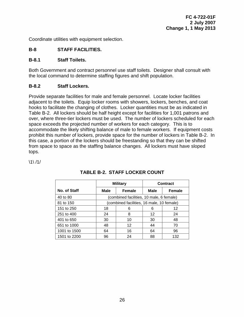
B-8.2 Staff Lockers.
Provide separate facilities for male and female personnel. Locate locker facilities adjacent to the toilets. Equip locker rooms with showers, lockers, benches, and coat hooks to facilitate the changing of clothes. Locker quantities must be as indicated in Table B-2. All lockers should be half height except for facilities for 1,001 patrons and over, where three-tier lockers must be used. The number of lockers scheduled for each space exceeds the projected number of workers for each category. This is to accommodate the likely shifting balance of male to female workers. If equipment costs prohibit this number of lockers, provide space for the number of lockers in Table B-2. In this case, a portion of the lockers should be freestanding so that they can be shifted from space to space as the staffing balance changes. All lockers must have sloped tops.
\1\ /1/
TABLE B-2. STAFF LOCKER COUNT
No. of Staff
Military Contract
Male Female Male Female 40 to 80 (combined facilities, 10 male, 6 female) 81 to 150 (combined facilities, 16 male, 10 female) 151 to 250 18 6 6 12 251 to 400 24 8 12 24 401 to 650 30 10 30 48 651 to 1000 48 12 44 70 1001 to 1500 64 16 64 96 1501 to 2200 96 24 88 132


