418
Facilities Management Design Guidelines THE UNIVERSITY OF TEXAS SOUTHWESTERN MEDICAL CENTER FACILITIES MANAGEMENT DEPARTMENT DESIGN GUIDELINES JUNE 19, 2020

Facilities Management
Design Guidelines
THE UNIVERSITY OF TEXAS SOUTHWESTERN MEDICAL CENTER
FACILITIES MANAGEMENT DEPARTMENT
DESIGN GUIDELINES
JUNE 19, 2020

Blank Page

Table of Contents
UTSW Facilities Management Design Guidelines TOC ‐ 1
Table of Contents 06/19/2020
TABLE OF CONTENTS

Table of Contents
UTSW Facilities Management Design Guidelines TOC ‐ 2
Table of Contents 06/19/2020
Blank Page

Table of Contents
UTSW Facilities Management Design Guidelines TOC ‐ 3
Table of Contents 06/19/2020
TABLE OF CONTENTS
Introduction I. General Information ii-3
II. Historically Underutilized Business Program ii-3 Section A - Design Philosophy
I. Design Philosophy A-3 II. Campus Design Standards A-3
III. Operating & Building Maintenance A-3 IV. Codes and Standards A-3 V. Texas State Energy and Conservation Office A-4
VI. Regulation Requirements A-4 VII. Environmental Practices: Sustainability, Energy,
and Water Conservation Design A-5 VIII. Environmental Practices: Daylighting A-6
IX. Environmental Practices: Building Materials A-6 X. Environmental Practices: Indoor Air Quality A-7
XI. Environmental Practices: Commissioning A-7 XII. Radiation and MRI Safety Design A-7
XIII. Building Core Elements: Emergency Command Center A-8 XIV. Building Core Elements: Egress Stairs A-8 XV. Building Core Elements: Mechanical Rooms A-8
XVI. Building Core Elements: Air-Handling Rooms A-9 XVII. Building Core Elements: Electrical Rooms/Closets A-9
XVIII. Building Core Elements: Rooftop Requirements A-10 XIX. Building Core Elements: Technology (TR) Room A-10 XX. Building Core Elements: Restrooms A-11
XXI. Building Core Elements: Janitor Closets and Elements A-11 XXII. Food Service A-12
XXIII. Parking and Garages A-14 XXIV. Accessibility A-14
XXV. Space Standards A-14 XXVI. Floor and Space Identification Systems on Drawings A-15
XXVII. Assignment of Room Numbers A-15
XXVIII. Assignment of Room Names A-15
XXIX. Institutional Design and Branding Committee A-15
XXX. Lactation Rooms A-15 XXXI. Vending Standards A-16
XXXII. Vibration Criteria in Buildings A-16
Exhibit A.1 (Reserved) A-17 Exhibit A.2 Room Numbering Standards A-18

Table of Contents
UTSW Facilities Management Design Guidelines TOC ‐ 4
Table of Contents 06/19/2020
Section A1 – Master Specifications I. General Information A1-3
Section A2 – Space Design Guidelines
I. General Information A2-3 Section A3 – Standard Details
I. General Information A3-3 Section A4 – Animal Resource Center (ARC) Design Requirements
I. General Information A4-3 II. Design A4-3
III. Section 03 00 00 Concrete A4-5 IV. Section 04 22 00 Concrete Unit Masonry A4-5 V. Section 07 90 00 Joint Protection A4-5
VI. Section 08 00 00 Doors and Frames A4-6 VII. Section 09 00 00 Finishes A4-6
VIII. Section 09 20 00 Plaster and Gypsum Board A4-6 IX. Section 09 22 16 Non-Structural Metal Framing A4-7 X. Section 06 80 00 Ceilings A4-7
XI. Section 09 60 00 Flooring A4-7 XII. Section 10 43 00 Emergency Aid Specialties A4-7
XIII. Section 10 50 00 Storage Specialties A4-7 XIV. Section 11 00 00 Equipment A4-7 XV. Section 12 35 53 Laboratory Casework A4-8
XVI. Section 12 36 00 Countertops A4-8 XVII. Section 12 50 00 Furniture A4-8
XVIII. Section 14 00 00 Conveying Equipment A4-8 XIX. Section 21 00 00 Fire Suppression A4-8 XX. Section 22 00 00 Plumbing A4-9
XXI. Section 23 00 00 Heating, Ventilating and Air Conditioning (HVAC) A4-9
XXII. Section 26 00 00 Electrical A4-10 XXIII. Section 27 00 00 Communications A4-11 XXIV. Section 28 00 00 Electronic Safety and Security A4-11
Division 00 00 00 – Procurement & Contracting Requirements
I. General Information 0-3 Division 01 00 00 – General Information
I. General Information 1-3 II. Acronyms 1-4

Table of Contents
UTSW Facilities Management Design Guidelines TOC ‐ 5
Table of Contents 06/19/2020
Division 02 00 00 – Existing Conditions I. General Information 2-3
II. Design Review Submittal Requirements 2-3 III. Section 02 21 00 Survey 2-3 IV. Section 02 26 00 Hazardous Materials Assessment 2-3 V. Section 02 32 00 Geotechnical Investigations 2-3
VI. Section 02 41 00 Demolition 2-4 VII. Section 02 82 00 Facility Remediation 2-5
Division 03 00 00 – Concrete
I. General Information 3-3 II. Design Review Submittal Requirements 3-5
III. Section 03 11 00 Concrete Forming 3-5 IV. Section 03 15 00 Concrete Accessories 3-5 V. Section 03 20 00 Concrete Reinforcing 3-5
VI. Section 03 30 00 Cast-in-Place Concrete 3-5 VII. Section 03 35 00 Concrete Finishing 3-6
VIII. Section 03 39 00 Concrete Curing 3-6 IX. Section 03 40 00 Precast Concrete 3-6 X. Section 03 50 00 Cast Decks and Underlayment 3-6
Division 04 00 00 Masonry
I. General Information 4-3 II. Design Review Submittal Requirements 4-3
III. Section 04 05 23 Masonry Accessories 4-3 IV. Section 04 20 00 Brick 4-3 V. Section 04 22 00 Concrete Masonry Units (CMU) 4-4
VI. Section 04 40 00 Stone 4-4 Division 05 00 00 - Metals
I. General Information 5-3 II. Design Review Submittal Requirements 5-3
III. Section 05 10 00 Structural Steel 5-3 IV. Section 05 12 13 Architecturally-Exposed
Structural Steel Framing 5-3 V. Section 05 30 00 Metal Decking 5-3
VI. Section 05 40 00 Cold-Formed Metal Framing 5-3 VII. Section 05 50 00 Metal Fabrications 5-4
VIII. Section 05 51 00 Metal Stairs 5-4 IX. Section 05 52 00 Metal Railings 5-4

Table of Contents
UTSW Facilities Management Design Guidelines TOC ‐ 6
Table of Contents 06/19/2020
Division 06 00 00 – Wood, Plastics, and Composites I. General Information 6-3
II. Design Review Submittal Requirements 6-3 III. Section 06 10 00 Rough Carpentry 6-3 IV. Section 06 16 00 Sheathing 6-3 V. Section 06 20 00 Finish Carpentry 6-3
VI. Section 06 41 00 Architectural Wood Casework 6-4 VII. Section 06 80 13 Resin Composite Paneling 6-4
VIII. Section 06 83 16 Fiberglass Reinforced Paneling 6-4
Division 07 00 00 – Thermal and Moisture Protection
I. General Information 7-3 II. Design Review Submittal Requirements 7-3
III. Section 07 10 00 Dampproofing and Waterproofing 7-3 IV. Section 07 18 00 Traffic Coatings 7-3 V. Section 07 21 00 Thermal Insulation 7-3
VI. Section 07 25 00 Weather Barriers 7-4 VII. Section 07 42 00 Wall Panels 7-4
VIII. Section 07 50 00 Membrane Roofing 7-4 IX. Section 07 60 00 Flashing and Sheet Metal 7-4 X. Section 07 70 00 Roof and Wall Specialties and Accessories 7-4
XI. Section 07 80 00 Fire and Smoke Protection 7-5 XII. Section 07 90 00 Joint Protection 7-5
XIII. Section 07 95 00 Expansion Control 7-5
Division 08 00 00 - Openings I. General Information 8-3
II. Design Review Submittal Requirements 8-4 III. Section 08 10 00 Doors and Frames 8-4 IV. Section 08 11 00 Metal Doors and Frames 8-5 V. Section 08 14 00 Wood Doors 8-5
VI. Section 08 30 00 Specialty Doors and Frames 8-5 VII. Section 08 31 13 Access Doors and Frames 8-5
VIII. Section 08 33 00 Coiling Doors and Grilles 8-6 IX. Section 08 34 00 Special Function Doors 8-6 X. Section 08 40 00 Entrances, Storefronts and Curtainwalls 8-6
XI. Section 08 50 00 Windows 8-6 XII. Section 08 70 00 Hardware 8-7
XIII. Section 08 80 00 Glazing 8-8 XIV. Section 08 90 00 Louvers and Vents 8-8

Table of Contents
UTSW Facilities Management Design Guidelines TOC ‐ 7
Table of Contents 06/19/2020
Division 9 00 00 - Finishes I. General Information 9-3
II. Design Review Submittal Requirements 9-3 III. Section 09 20 00 Plaster and Gypsum Board Assemblies 9-4 IV. Section 09 22 16 Non-Structural Metal Framing 9-4 V. Section 09 30 00 Tiling 9-5
VI. Section 09 50 00 Ceiling 9-6 VII. Section 09 60 00 Flooring 9-6
VIII. Section 09 65 00 Resilient Flooring 9-7 IX. Section 09 66 00 Terrazzo Flooring 9-7 X. Section 09 67 23 Resinous Flooring 9-7
XI. Section 09 68 00 Carpeting 9-7 XII. Section 09 70 00 Wall Finishes 9-8
XIII. Section 09 72 00 Wall Covering 9-8 XIV. Section 09 73 00 Wall Carpeting 9-8 XV. Section 09 90 00 Painting and Coating 9-9
XVI. Section 09 90 01 Interior Painting 9-9 XVII. Section 09 91 13 Exterior Painting 9-9
XVIII. Section 09 96 00 High-Performance Coatings 9-9 XIX. Section 09 97 00 Special Coatings 9-9 Division 10 00 00 - Specialties
I. General Information 10-3 II. Design Review Submittal Requirements 10-3
III. Section 10 10 00 Information Specialties 10-3 IV. Section 10 11 16 Markerboards and Glassboards 10-3 V. Section 10 11 23 Tackboards 10-3
VI. Section 10 12 00 Display Cases 10-4 VII. Section 10 13 00 Directories 10-4
VIII. Section 10 14 00 Signage and Wayfinding 10-4 IX. Section 10 21 13 Toilet Compartments 10-4 X. Section 10 21 23 Cubicle Curtain and Track 10-5
XI. Section 10 22 19 Demountable Partitions 10-5 XII. Section 10 22 23.23 Movable Panel Systems 10-5
XIII. Section 10 22 39 Folding Panel Partitions 10-5 XIV. Section 10 25 00 Patient Bed Service Walls 10-5 XV. Section 10 26 00 Wall and Door Protection 10-6
XVI. Section 10 26 23 Protective Wall Covering 10-6 XVII. Section 10 28 13 Toilet and Bath Accessories 10-6
XVIII. Section 10 44 00 Fire Protection Specialties 10-7 XIX. Section 10 50 00 Storage Specialties 10-7 XX. Section 10 56 00 Storage Shelving 10-8
XXI. Section 10 81 00 Pest Control Devices 10-8 XXII. Section 10 81 01 Knox Boxes / Emergency Key Boxes 10-8
XXIII. Section 10 99 00.01 Emergency Aid Specialties 10-9 Exhibit 10.1 Standard Toilet Accessories 10-10

Table of Contents
UTSW Facilities Management Design Guidelines TOC ‐ 8
Table of Contents 06/19/2020
Division 11 00 00 - Equipment
I. General Information 11-3 II. Design Review Submittal Requirements 11-3
III. Section 11 12 00 Parking Control Equipment 11-3 IV. Section 11 13 00 Loading Dock Equipment 11-3 V. Section 11 30 00 Residential Equipment 11-3
VI. Section 11 40 00 Foodservice Equipment 11-3 VII. Section 11 52 00 Audio-Visual Equipment 11-4
VIII. Section 11 53 00 Laboratory Equipment 11-4 IX. Section 11 70 00 Healthcare Equipment 11-7
X. Section 11 81 29 Facility Fall Protection 11-7 XI. Section 11 97 00 Security Equipment 11-7
Exhibit 11.1 Media Technology Audiovisual 11-8 Division 12 00 00 - Furnishings
I. General Information 12-3 II. Design Review Submittal Requirements 12-3
III. Section 12 10 00 Art 12-3 IV. Section 12 20 00 Window Treatments 12-3 V. Section 12 24 00 Motorized Window Shades 12-3
VI. Section 12 26 00 Wall and Door Protection 12-3 VII. Section 12 30 00 Casework 12-4
VIII. Section 12 36 00 Countertops 12-4 IX. Section 12 40 00 Furnishings and Accessories 12-4 X. Section 12 46 19 Clocks 12-4
XI. Section 12 48 00 Rugs and Mats 12-4 XII. Section 12 50 00 Furniture 12-4
XIII. Section 12 52 00 Seating 12-5 XIV. Section 12 93 13 Bicycle Racks 12-5 Division 13 00 00 – Special Construction
I. General Information 13-3 II. Design Review Submittal Requirements 13-3
III. Section 13 21 00 Control Environment Rooms 13-3 IV. Section 13 49 00 Radiation Protection 13-3

Table of Contents
UTSW Facilities Management Design Guidelines TOC ‐ 9
Table of Contents 06/19/2020
Division 14 00 00 – Conveying Equipment I. General Information 14-3
II. Design Review Submittal Requirements 14-4 III. General Requirements 14-4 IV. Traction Elevators 14-5 V. Hydraulic Elevators 14-5
VI. Elevator Components 14-6 VII. Signaling 14-11
VIII. Safety 14-12 IX. Escalators 14-12
Division 21 00 00 – Fire Suppression
I. General Information 21-3 II. Design Review Submittal Requirements 21-3
III. Section 21 13 13 Fire Sprinkler Systems 21-3 IV. Section 21 20 00 Installation of Kitchen Extinguishing System
(Dry/Wet Chemical) 21-4 V. Section 21 22 00 Clean Agent Fire Extinguishing System 21-4
Division 22 00 00 - Plumbing I. General Information 22-3
II. Design Review Submittal Requirements 22-4 III. Metering 22-4 IV. Section 22 10 00 Piping 22-4 V. Section 22 11 16 Domestic Piping 22-5
VI. Section 22 13 00 Sanitary Sewage 22-5 VII. Section 22 14 00 Storm Drainage 22-6
VIII. Section 22 40 00 Plumbing Fixtures 22-6 IX. Section 22 60 00 Gas and Vacuum for Laboratory 22-7 X. Section 22 66 00 Chemical-Waste System for Laboratory 22-8
XI. Section 22 67 00 Processed Water System for Laboratory 22-8 Division 23 00 00 – Heating, Ventilating, and Air Conditioning
I. General Information 23-3 II. Design Review Submittal Requirements 23-4
III. HVAC – Renovation General Design Guidelines 23-4 IV. HVAC – General Planning Criteria 23-5 V. Cooling And Heating Load Calculations 23-5
VI. Outdoor Design Conditions 23-6 VII. Research Labs Spaces HVAC System 23-6
VIII. Office Spaces HVAC System 23-7 IX. Clinic Spaces HVAC System 23-7 X. Automatic Temperature Controls 23-7
XI. Energy Management System 23-7 XII. Section 23 05 19 Meters 23-7
XIII. Section: 23 05 23 Valves for HVAC Piping 23-8

Table of Contents
UTSW Facilities Management Design Guidelines TOC ‐ 10
Table of Contents 06/19/2020
XIV. Section 23 05 48 Vibration Controls for HVAC 23-8 XV. Section 23 07 13 Duct Insulation 23-8
XVI. Section 23 20 00 HVAC Piping and Pumps 23-8 XVII. Section 23 21 13 Hydronic Piping 23-9
XVIII. Section 23 21 23 Chilled Water And Heating Hot Water Pumps 23-9 XIX. Section 23 31 00 HVAC Ducts and Casings 23-10 XX. Section 23 35 00 Special Exhaust Systems 23-12
XXI. Section 23 36 13 Variable-Air-Volume Units 23-12 XXII. Section 23 37 13 Diffusers and Dampers 23-13
XXIII. Section 23 41 00 Air Filtration 23-14 XXIV. Section 23 73 00 Indoor Air-Handling Units 23-14 XXV. Section 23 82 19 Fan Coil Units 23-15 Division 25 00 00 – Integrated Automation
I. General Information 25-3 II. Design Review Submittal Requirements 25-3
III. Automatic Temperature Controls 25-3 IV. Building Automation System 23-3 V. DDC System Manufacturer 23-3
VI. FM Capital Projects 23-3 Division 26 00 00 - Electrical
I. General Information 26-3 II. Design Review Submittal Requirements 26-3
III. Utilization Voltages 26-3 IV. Services Outages 26-3 V. Medium-Voltage Cables 26-3
VI. Low-Voltage Electrical Power Conductors and Cables 26-4 VII. Section 26 09 00 Metering 26-4
VIII. Section 26 10 00 Medium-Voltage Electrical Distribution 26-5 IX. Division 26 10 00 Low-Voltage Electrical Distribution 26-5 X. Section 26 41 00 Facility Lightning Protection 26-8
XI. Section 26 50 00 Lighting 26-9 XII. Section 26 51 00 Interior Lighting 26-10
XIII. Section 26 52 00 Safety Lighting 26-11 XIV. Section 26 56 00 Exterior Lighting 26-11
Division 27 00 00 - Telecommunications
I. General Information 27-3 II. Design Review Submittal Requirements 27-3
III. Technology Room (TR) Guidelines 27-3 IV. Section 27 05 00 Common Work Results for
Communications 27-5 V. Section 27 05 26 Grounding and Bonding for
Communications Systems 27-5 VI. Section 27 05 28 Pathways for Communications Systems 27-6

Table of Contents
UTSW Facilities Management Design Guidelines TOC ‐ 11
Table of Contents 06/19/2020
VII. Section 27 05 53 Identification for Communications Systems 27-6 VIII. Section 27 07 00 Communications Testing 27-6
IX. Section 27 10 00 Structured Cabling 27-7 X. Section 27 11 16 Communications Cabinets, Racks,
Frames and Enclosures 27-9 XI. Section 27 15 43 Communications Faceplates and Connectors 27-9
XII. Section 27 16 19 Communications Patch Cords and Station Cords 27-9
XIII. Communications Firestopping Guidelines and Products 27-10 XIV. Execution 27-10 XV. Submittals 27-11
XVI. Quality Assurance 27-12 XVII. Additional Communications Information and Notes 27-12
XVIII. Section 27 42 00 Point of Sale Systems (POS) 27-13
Exhibit 27.1 TR Room Rack Typical Layout 27-14 Exhibit 27.2 Technology Room Typical Layout 27-15 Exhibit 27.3 Partial Rack Configuration 27-16 Exhibit 27.4 Photos of Completed Technology Room 27-17 Exhibit 27.5 Technology Room Grounding Busbar 27-18 Division 28 00 00 – Electronic Safety and Security
I. General Information 28-3 II. Design Review Submittal Requirements 28-3
III. Section 28 05 37 Security Voice Communications – Distributed Antenna System (DAAS) 28-3
IV. Section 28 10 00 Access Control 28-3 V. Section 28 20 00 Video Surveillance 28-4
VI. Section 28 31 00 Addressable Fire Alarm System 28-4 Division 31 00 00 - Earthwork
I. General Information 31-3 II. Design Review Submittal Requirements 31-3 III. Section 31 10 00 Site Clearing 31-3 IV. Section 31 22 00 Grading 31-4 V. Section 31 23 00 Excavation and Fill 31-5 VI. Section 31 31 00 Soil Treatment 31-6 VII. Section 31 32 00 Soil Stabilization 31-6
Division 32 00 00 – Exterior Improvements
I. General Information 32-3 II. Design Review Submittal Requirements 32-3
III. Section 32 10 00 Bases, Ballasts, and Paving 32-3 IV. Section 32 12 16 Asphalt Paving 32-5 V. Section 32 13 13 Concrete Paving 32-5
VI. Section 32 13 16 Decorative Concrete Paving 32-5 VII. Section 32 14 00 Unit Paving 32-5

Table of Contents
UTSW Facilities Management Design Guidelines TOC ‐ 12
Table of Contents 06/19/2020
VIII. Section 32 16 00 Curbs, Gutters, Sidewalks, and Driveways 32-5 IX. Section 32 17 00 Paving Specialties 32-6 X. Section 32 31 00 Fences and Gates 32-7
XI. Section 32 32 00 Retaining Walls 32-7 XII. section 32 33 00 Site Furnishings 32-7
XIII. Section 32 80 00 Irrigation 32-7 XIV. Section 32 90 00 Planting 32-9 XV. Section 32 92 00 Turf and Grasses 32-9
XVI. Section 32 93 00 Plants 32-10 XVII. Section 32 93 13 Ground Covers 32-10
XVIII. Section 32 93 23 Plants and Perennials 32-10 XIX. Section 32 93 33 Shrubs 32-11 XX. Section 32 93 43 Trees 32-11
Division 33 00 00 - Utilities
I. General Information 33-3 II. Design Review Submittal Requirements 33-3
III. Section 33 05 00 Concrete Utility Boxes 33-3 IV. Section 33 10 00 Water Utilities 33-3 V. Section 33 30 00 Sanitary Sewerage 33-4
VI. Section 33 40 00 Stormwater Utilities 33-5 VII. Section 33 60 00 Chilled and Heating Water Distribution 33-6 VIII. Section 33 71 19 Electrical Distribution –
Underground Ductbanks 33-7 IX. Section 33 71 19.13 Power Manholes 33-7 X. Section 33 80 00 Data/Telecomm Distribution 33-8 XI. Site Lighting 33-8 XII. Section 33 05 61 Manhole Covers 33-8
Section B – Submittal Requirements for Design Documents Introduction B-3 Deliverables Required for All Projects B-3 Documentation Format for All Projects B-8 Standard Drawing Set Requirements for All Projects B-8 Cover Sheet B-8 Title Block B-9 Project Data Sheet B-9 Standard Accessibility Sheet B-9 Equipment Schedules and Coordination B-9 Construction Administration and Closeout Requirements for All Projects B-10 Office of Safety and Business Continuity (OSBC) Coordination Requirements B-11

Table of Contents
UTSW Facilities Management Design Guidelines TOC ‐ 13
Table of Contents 06/19/2020
Exhibit B.1 Pending Issues Report B-13 Exhibit B.2 UTSW CAD Standards B-14 Exhibit B.3 UTSW Archibus Export Requirements B-15 Exhibit B.4 Storm Water Pollution Prevention Plan (SWPPP) Deliverables B-18 Exhibit B.5 UTSW BIM Standards B-24 Section B1 – CIP Deliverables Introduction B1-3 Deliverables Required for All Projects B1-3 Programming Phase B1-3 Schematic Design Development Phase B1-4 Design Development Phase B1-11 Construction Document Phase B1-21 Exhibit B1.1 Basic Data B1-31 Exhibit B1.2 Cost Quantity Survey B1-33 Section B2 – Renovation Deliverables
Introduction B2-3
Deliverables Required for All Projects B2-3 Preliminary Building Assessment B2-3 Potential Additional Services B2-3 Design Development Phase B2-4 Construction Documents B-10 Section C – Codes and Standards
I. General Requirements C-3 II. Design Basis C-4
III. Architectural Design C-4 IV. Civil and Structural Design C-5 V. Mechanical and Plumbing Design – OCP Managed Projects C-5
VI. Electrical Design C-5 VII. Energy & Water Conservation Design C-5
VIII. Code Compliance Confirmation Reviews C-6 Exhibit C.1 Excerpts from TDI Commissioner’s Order No. 4015 C-7 Exhibit C.2 Building Code Analysis (Template) C-11 Exhibit C.3 Code Compliance Confirmation Review (Template) C-12 Exhibit C.4 UTSW Specific Information C-14 Section C1 – Definitions
I. General Information C1-3

Table of Contents
UTSW Facilities Management Design Guidelines TOC ‐ 14
Table of Contents 06/19/2020
DOCUMENT HISTORY Issue Date Description Editor
06/19/2020 June 19, 2020 Print EV

Introduction
UTSW Facilities Management Design Guidelines ii - 1 Introduction 06/19/2020
INTRODUCTION

Introduction
UTSW Facilities Management Design Guidelines ii - 2 Introduction 06/19/2020
Blank Page

Introduction
UTSW Facilities Management Design Guidelines ii - 3 Introduction 06/19/2020
INTRODUCTION
I. General Information
A. The Facilities Management Department Design Guidelines are intended as guidance for
the project Architect/Engineer (A/E) team and the Contractor team during the planning,
design, and construction processes for The University of Texas Southwestern Medical
Center (UTSW) Capital Improvement Projects (CIP) and Renovation Projects. The
content also covers specific design criteria, design processes, and administrative
processes for permanent buildings on UTSW Campuses, renovations of buildings on
UTSW campuses, and renovations in leased spaces.
B. Renovations in buildings not owned by UTSW will incorporate the requirements of the
respective city in which the project is located. Requirements of the Office of Safety and
Business Continuity (OSBC) shall be incorporated into all of these renovations.
C. Many, but not all, requirements for each Campus or Off-Site Leased Spaces are covered.
The Project A/E, CM-R or D-B shall also refer to items covered in their respective
Services Agreement and the Project Scope.
D. In the event of conflict between these guidelines and specific project requirements, the
A/E, CM-R or D-B shall contact the UTSW Project Manager (UTSW PM) who shall
coordinate clarification by the Director of Planning, Design and Renovations.
E. The guidelines in this document are not intended to prohibit the use of alternative
methods, systems, products or devices not covered in this document. All alternatives
shall be documented by the A/E, CMAR and D-B and submitted to for approval by the
Director of Planning, Design and Renovations.
F. Throughout these Guidelines and under Campus Specific Information, there are
references to single products and/or manufacturers. These are NOT intended to be sole
source items unless specifically noted. The project A/E is required to identify and include
in the Contract Documents at least three (3) comparable products and/or
manufacturers.
II. Historically Underutilized Business Program
A. The University of Texas Southwestern Medical Center Office of Facilities Management
Department is committed to promoting the participation of minority, women-owned,
and small businesses through the Historically Underutilized Business (HUB) Program for
the procurement of goods and/or services. The procurement process utilized by UTSW
seeks to provide equal opportunity and equal access in the design and construction
opportunities on projects managed by the Facilities Management Department.
End of Introduction

Introduction
UTSW Facilities Management Design Guidelines ii - 4 Introduction 06/19/2020
DOCUMENT HISTORY Issue Date Description Editor
06/19/2020 June 19, 2020 Print EV

Design Criteria
Section A – Design Philosophy
UTSW Facilities Management Design Guidelines A - 1 Section A – Design Philosophy 06/19/2020
DESIGN PHILOSOPHY
SECTION A

Design Criteria
Section A – Design Philosophy
UTSW Facilities Management Design Guidelines A - 2 Section A – Design Philosophy 06/19/2020
Blank Page

Design Criteria
Section A – Design Philosophy
UTSW Facilities Management Design Guidelines A - 3 Section A – Design Philosophy 06/19/2020
SECTION A – DESIGN PHILOSOPHY
I. Design Philosophy
A. The University of Texas Southwestern Medical Center Facilities Management Department
is committed to excellence in the design of capital projects for new and existing buildings
for the UTSW various campuses. To accomplish this, the institution is committed to the
highest quality of aesthetics in meeting the requirements of the various buildings while at
the same time delivering a project that is cost-effective to operate and maintain
throughout its useful life. B. All capital projects shall be designed with flexibility and adaptability as a core objective.
Over the life of campus buildings, the functions will change, and spaces will be
reconfigured or repurposed.
II. Campus Design Standards
A. Capital project designs shall conform to the guidelines in this document and the guidelines
and standards established by the University Institutional Design and Branding Committee
(IDBC). B. Capital projects shall conform to the UTSW master plan guidelines. In the event of a
conflict between these Design Guidelines, the UTSW master plan, and the standards
established by the IDBC, the Director of Planning, Design and Renovations will coordinate
with the Vice President of the Facilities Management Department for a resolution.
III. Operating and Building Maintenance
A. Systems and materials incorporated into capital projects should be selected on the basis of
life cycle operations and maintenance costs. The design should incorporate ease and
efficiency of operation and allow for easy, safe and cost-effective maintenance and repair.
Standardization of equipment, parts, and components is also the key to reducing
maintenance costs and allows for stocking of common replacement parts. B. The Project A/E should obtain constant feedback from the Facilities Management
Department during design. Detailed instructions from the Project A/E stating the design
intent for capital projects or modification of all building systems and the
operating/maintenance procedures are required during the design process. C. Refer to other Design Guideline Sections for additional requirements in the design process. D. Design preference is for buildings to have parapets designed to comply with OSHA
requirements for fall protection. If a parapet is not provided, the design shall provide
alternative safety systems such as an engineered davit system to comply with OSHA
(OSBC).
IV. Codes and Standards
A. Compliance with all state and federal laws applicable to construction is expected. As
authorized by the VP, FM, Design and Renovations, the Project A/E and the UTSW PM shall
coordinate with municipalities as necessary.

Design Criteria
Section A – Design Philosophy
UTSW Facilities Management Design Guidelines A - 4 Section A – Design Philosophy 06/19/2020
B. The Project A/E shall design projects to comply with current editions of the codes and
standards indicated in Section C and advise the Owner of code revisions having impact on
the project design. The Office of Safety and Business Continuity (OSBC) is the Authority
Having Jurisdiction (AHJ) for NFPA for on-campus projects. C. Refer to Section C – Codes and Standards for a complete list of UTSW applicable codes and
standards and the approved editions. 1. Additionally, projects shall meet the minimum requirements of OSHA, but specific
project situations may dictate additional safety requirements above these minimums.
In these cases, A/Es shall request a review with OSBC so they may assess and make
further recommendations.
V. Texas State Energy and Conservation Office
A. The Texas State Energy and Conservation Office (SECO) was created by the state
legislature to establish minimum energy standards for state agencies and institutions of
higher education. SECO has created and references minimum guidelines to be
incorporated into new construction and “major renovations”. SECO has forms that are
required to be completed by the A/E team and submitted to the UTSW PM. The UTSW PM
will review and submit to the Director of Planning, Design, and Renovations for submission
to SECO. B. Refer to Section C – Codes and Standards for a complete list of SECO codes and standards
and the approved editions. The compliance forms are also indicated in Section C.
VI. Regulation Requirements
A. The A/E will provide a summary of any permits required from the local, state, and federal
government agencies to the UTSW PM for review and approval. The City of Dallas, Texas
Department of Highways and Public Transportation, and the Texas Health Department are
an example of local municipalities that may require permits. The cost of any permits will
be borne by the Owner. B. The Project A/E is required to submit sealed documents for an accessibility review per
State requirements. The required review should be accomplished by a Registered
Accessibility Specialist (RAS) located near the project site. The same RAS will be utilized for
the plan review and the post-construction inspection unless otherwise approved by UTSW
PM. C. Upon receipt of the completed plan review, the A/E shall provide a corrective action plan
to the UTSW PM that addresses all non-compliant issues within the A/E scope. This plan
shall ensure the design is code compliant and shall be reviewed with the UTSW PM for
approval. Issues outside of A/E scope shall be identified by the A/E to UTSW PM. Upon
final direction from UTSW PM, the A/E shall confirm when all items have been corrected in
the documentation through the issuance of updated documents showing completion of
the corrective action plan. D. Refer to Section B – Submittal Requirements for Design Documents, “Deliverables
Required for All Projects” for additional information.

Design Criteria
Section A – Design Philosophy
UTSW Facilities Management Design Guidelines A - 5 Section A – Design Philosophy 06/19/2020
VII. Environmental Practices: Sustainability, Energy, and Water Conservation Design A. The capital project design will be required to conform to LEED criteria wherever possible,
as determined in consultation with the project Steering Committee or VP FM. Sustainable
practices, materials, and goals should be considered for each project as appropriate. The
A/E shall coordinate with the UTSW PM for what should be recommended to the project
Steering Committee or VP FM. B. Designs following these applicable principles improve the building’s performance while
enhancing the occupant’s health, safety, and welfare. C. The energy performance and water conservation designs incorporated into new buildings
and “major renovations” shall conform to requirements and codes as adopted by the
Texas State Energy and Conservation Office (SECO). The A/E shall coordinate with UTSW
PM for what should be considered for each project. D. Energy Efficiency for Lighting and Mechanical Systems
1. At least 5% above the minimum requirements outlined in 90.1 ASHRAE and IECC or
most up to date energy code.
2. Employ a life-cycle cost study to determine Return On Investment (ROI) timeline and
present the results to UTSW. Perform the analysis with up- front costs, energy costs,
maintenance costs, and end of life costs, for at least 4 of these concepts, or for other
energy efficient measures under consideration:
a. High-performance envelopes and glazing (required)
b. Active building shading
c. Active chilled beams (in non-patient care areas)
d. Heat and/or energy recovery options
e. Geothermal / thermal storage
f. Photovoltaics
3. Demonstrate compliance with 5% improvement via a whole-building energy
model or COMcheck compliance software demonstrating compliance for the
Envelope, Mechanical Systems, and Lighting as is in project scope.
4. Energy Star appliances are required.
5. Potential strategies to improve energy performance include, but are not limited
to:
a. Orienting buildings East-West direction
b. Improved insulation levels
c. Improved glazing performance
d. Higher performing mechanical equipment
e. Colored roof materials
f. Improved access to daylighting with daylight sensors and/or
occupancy sensors to reduce lighting needs
g. High performance lighting
h. Light-colored exterior paving
E. Water Efficiency

Design Criteria
Section A – Design Philosophy
UTSW Facilities Management Design Guidelines A - 6 Section A – Design Philosophy 06/19/2020
1. 20% indoor water use reduction beyond the Energy Policy Act (EPAct) of 1992.
2. Employ a life-cycle cost study to determine Return On Investment (ROI) timeline and
present the results to UTSW. Perform the analysis with up-front costs, usage costs,
maintenance costs, and end of life costs.
3. Demonstrate compliance with the minimum 20% reduction by one of the following:
a. Provide interior water use reduction calculator demonstrating 20% reduction
b. Ensure that all eligible fixtures carry the EPA's WaterSense label.
c. All eligible products on site have flush/flow rates at or below these thresholds:
i. Water Closet - 1.28 GPF
ii. Urinal - 0.125 GPF
iii. Private Faucet - 1.75 GPM
iv. Public Faucet - 0.4 GPM
v. Breakroom/Kitchen Faucet - 1.75 GPM
vi. Shower - 1.8 GPM
4. If applicable, 30% exterior water use reduction
5. Comply with the most recent "Water Conservation Design Standards For State
Buildings and Institutions of Higher Education Facilities" adopted by the Texas
Legislature (34 Tex. Admin. Code §19.32) and the State Energy Conservation Office
(SECO). Before beginning construction of a new state building or state-supported
higher education facility, a water conservation compliance certification form must be
completed and submitted to SECO to document compliance with the standards.
6. Confirm which water reuse strategy (Rainwater Harvesting, treated graywater,
condensate collection or cooling tower blowdown, or a combination of these
strategies) is to be employed on this project if the project exceeds a 10,000 sf roof per
SECO requirements
VIII. Environmental Practices: Daylighting A. In order to maintain a relationship between the building occupants and the outdoors,
direct views of the outside should be provided or maintained for most of the regularly
occupied areas unless the needs of the spaces dictate otherwise.
IX. Environmental Practices: Building Materials
A. Wherever possible, products and materials with recycled-content and no volatile organic
compounds (VOC) should be specified in capital project design. A/E team shall ensure that
non-fibrous materials are specified. B. Add notes to general specifications and drawing notes for General Contractor to supply to
UTSW PM a certification letter and certification letters from all sub-contractors that no
asbestos containing materials were used during construction. These certificates shall be
notarized and submitted within the Close Out Documentation. C. All materials used on projects shall be certified as non-Asbestos Containing Building
Materials (ACBM). Refer to Owner’s Special Conditions for additional requirements and
UTSW PM shall file notarized certification statements in the project’s O&M file.

Design Criteria
Section A – Design Philosophy
UTSW Facilities Management Design Guidelines A - 7 Section A – Design Philosophy 06/19/2020
X. Environmental Practices: Indoor Air Quality A. FM capital projects designs shall comply with ASHRAE 62.1- latest edition.
XI. Environmental Practices: Commissioning
A. All FM capital projects shall employ appropriate commissioning practices to assure delivery
of program goals and related performance requirements. The Project A/E shall coordinate
commissioning practices with the UTSW PM, the UTSW Maintenance Department, the
Commissioning Authority (if contracted) and the contractor (if the delivery method is
construction manager at risk or design-build) during design. Commissioning scope and
practices are to comply with current FM capital project standards.
XII. Radiation and MRI Safety Design
A. Refer to Section C, Radiation Safety Control for code requirements in the UTSW Design
Guidelines
B. The UTSW Medical Physics group will provide to the UTSW PM and A/E the project
shielding design based on the machine type, manufacturer, number of exams to be
performed, and room use adjacent to the x-ray room. This shall be used for coordination
of infrastructure needs.
1. When the contractor has completed the shielding installation, but before walls are
closed up, the UTSW Medical Physics team shall be notified for inspection. This team
shall inspect and verify if the shielding design was followed. Walls shall only be closed
once the installation is verified.
C. MRI spaces shall include the following in their projects:
1. Badge readers – refer to Section 28 10 00 Access Control
2. Signage
a. A lighted sign shall be above the door to the MRI Zone IV (or Zone III as
applicable). If this location is not feasible, an alternative location shall be
determined by the UTSW Office of Safety and Business Continuity’s Director of
Radiation Safety or their representative
b. The sign shall be wired to the building electrical system in accordance with NFPA
70 (2014 ed.). If primary power is lost, the sign shall have battery backup
providing not less than 24 hours of internal illumination, or be wired to the
emergency electrical backup generator if the building has generator backup.
c. The sign shall be internally illuminated with the words “Magnet Always On” and
be red in color on a contrasting white background
d. The sign shall be fastened to the wall according to the manufacturers
specifications
3. Refer to other sections of the UTSW Design Guidelines:
a. Quench Ventilation – Refer to Division 23 for Special Exhaust Systems
b. Fire Alarm Devices – Refer to Division 28 for Addressable Fire Alarm Systems
c. Fire Extinguisher – Refer to Division 10 for Fire Protection Specialties

Design Criteria
Section A – Design Philosophy
UTSW Facilities Management Design Guidelines A - 8 Section A – Design Philosophy 06/19/2020
XIII. Building Core Elements: Emergency Command Center
A. Hi-rise buildings shall have an exterior entrance to the Emergency Command Center
B. Where required, an Emergency Command Center shall contain a minimum of the following
equipment required in the Code and shall also include the following:
1. Table and chair
2. Building Plans: Architecture, Mechanical, Electrical, Plumbing and all Fire Protection
Plans
3. Floor map of each floor
4. Smoke Control Control Board, where applicable
5. All lighting and electrical outlets shall be on emergency generator power
6. Data ports and/or WIFI in the room
XIV. Building Core Elements: Egress Stairs
A. Doors entering egress stairs from within a building shall not be locked or prevent access.
Locked exit doors at egress stairs with card readers in the stair area shall be connected to
the fire alarm system and release the door for occupant egress during a general alarm.
Egress doors shall open to follow the direction of the path of travel or as required by code.
XV. Building Core Elements: Mechanical Rooms
A. All mechanical rooms added or modified during FM capital projects must be designed with
adequate aisle space and clearances around equipment to accommodate maintenance
from the floor and replacement of items.
B. There must be a defined pathway from all mechanical rooms to the building exterior of
adequate size to permit the replacement of equipment. Means of removal of equipment
shall be by the most cost efficient path approved by UTSW PM and UTSW FM.
C. Enlarged plans and elevations for all added mechanical rooms, at a scale not less than 1/4"
= 1’-0”, shall be prepared for each room to indicate that adequate circulation and
maintenance areas are provided
D. The A/E shall model all required clearances and pulls required for maintenance and repair
of equipment for coordination purposes
E. All mechanical rooms must be designed to control noise transmission to adjacent spaces
including corridors
F. Sound transmission through mechanical room walls shall not cause adjacent space’s noise
levels to be exceeded per values indicated in Acoustic Design sections
G. Depress the floor of all mechanical rooms 1-1/2 inches and uniformly slope the entire floor
to the required number of 4-inch floor sinks connected to the building sanitary sewer
system as required by code or as directed by UTSW PM and UTSW FM. Slopes shall follow
requirements from Division 22 in the UTSW Design Guidelines.
H. Refer to Electrical Rooms/Closets for space requirements for electrical panel boards
including access and egress
I. Refer to Divisions 22, 23, and 26 in the UTSW Design Guidelines

Design Criteria
Section A – Design Philosophy
UTSW Facilities Management Design Guidelines A - 9 Section A – Design Philosophy 06/19/2020
XVI. Building Core Elements: Air-Handling Rooms
A. Air Handler rooms added in FM capital projects should be designed so that NO wall is
centered on a structural beam that would interfere with vertical risers
B. The spaces must be arranged and sized to provide maintenance staff with safe access to all
pieces of equipment for routine maintenance
C. Access to air handler rooms must be from within the building from the corridor system
and not through any other space. Door should open out from space to maximize usable
interior floor and wall area.
D. Provide a minimum of 2 feet clearance on two sides and one end of the air handlers.
Provide clearance for removing coils and filters.
E. Air handler rooms shall be insulated for sound. Refer to Mechanical Rooms above in
Section A for requirements on sound transmission and spaces required for electrical
equipment.
F. Refer to Divisions 22 and 23 in the UTSW Design Guidelines
XVII. Building Core Elements: Electrical Rooms/Closets
A. Electrical rooms/closets added in FM capital projects must be designed so that NO wall is
centered on a structural beam that would interfere with vertical risers.
B. Do not route mechanical or plumbing utilities capable of conveying air or liquids through
or above electrical rooms/closets. The only exception allowed is the branch sprinkler line
serving only the sprinkler head in an electrical room/closet.
C. Access to electrical rooms/closets must be from within the building and not through any
other spaces. Doors should open out from the rooms into the corridor system to maximize
usable interior floor and wall area.
D. Electrical rooms with electrical equipment rated 1,200 amperes and over is considered
“large equipment” and:
1. Required to have two means of exit
2. Required to have one door at each end of room
3. Required to have panic hardware on doors. One entrance to should have double
doors for oversized equipment. Or single door as allowed by NEC 110.
4. Doors shall open in the direction of the path of travel
E. Enlarged plans for all electrical rooms/closets, at a scale not less than 1/4" = 1’-0”, shall be
prepared for each electrical/closet room
F. Sound transmission through electrical room walls shall not cause adjacent space’s noise
levels to be exceeded per values indicated in Acoustic Design
G. Lighting in electrical rooms and at panel boards located in other spaces shall not be
controlled by automatic means only per NEC 110.26
H. Refer to Division 26 in the UTSW Design Guidelines

Design Criteria
Section A – Design Philosophy
UTSW Facilities Management Design Guidelines A - 10 Section A – Design Philosophy 06/19/2020
XVIII. Building Core Elements: Rooftop Requirements
A. The design of building rooftops shall be discussed in early programmatic stages to assist in
determining building heights and building systems appropriate for the project. UTSW
Building Envelope Coordinator shall be included as a stakeholder from these early stages.
B. The roofing membrane systems shall provide a long-term, high performance protection for
the building. Membrane selection shall consider the potential chemical output from
rooftop equipment such as exhaust fans. Design of slopes and drains shall promote
positive runoff from the building in a rapid manner, preventing ponding.
C. The overall design of roof areas shall assure safe maintenance access to all pieces of
equipment as well as to the entire roofing surface for inspection and repair of the
membrane. Roof layouts and drawings shall include equipment clear floor areas as well as
required clearances for proper operation. Locations of equipment, piping, rooftop hoists,
access points, davits, roof drains, etc. shall be organized in a holistic design that optimizes
access and membrane preservation. One example is to minimize piping runs crossing the
main walking path which can be trip hazards as well as causing damage to the membrane.
D. UTSW preference is for an elevator to open at roof levels to allow easy access for
equipment repairs and updates. The elevator, opening, and hoistway shall be protected
from weather infiltration to protect the machines from damage.
E. If UTSW determines that elevator access is not possible, a stairway shall extend up to the
roof
F. Rooftop areas shall provide OSHA required fall protection or prevention systems in all
areas. Any elevation variations between roof areas shall be accessed with either a
permanent ladder or roof hatch with a permanent ladder.
G. A/E shall designate walk paths to reach all pieces of equipment and access points.
Additional walk-path areas shall be designed adjacent to and around large pieces of
equipment to allow for lay-down or tool placement during repairs.
H. Roof surfaces with equipment shall be screened with parapets or engineered equipment
screens. Aesthetics, maintenance and cost shall be considered in the design of screening
elements to ensure a long-term, positive solution. Screens shall not limit access to
equipment or restrict manufacturer required clearances for service or air flow. Structural
requirements including bracing shall be designed in a manner to minimize roof
penetrations while meeting the code requirements for wind and safety.
XIX. Building Core Elements: Technology Room (TR) Requirements
A. Information Resources (IR) Technology Rooms (TR) added in FM capital projects must be
designed so that NO wall is centered on a structural beam that would interfere with
vertical risers. A TR shall be provided on each floor and located so cable length complies
with requirements set out in Division 27 of the UTSW Design Guidelines.
B. Access to TR must be from within the building and from the corridor system; openings
from intermediate spaces are not allowed
C. Door should open out from the TR to maximize usable interior floor and wall area. In
limited locations, when an outward opening door would impede corridor width, A/E shall
carefully coordinate door placement with IR to maximize interior space and wall space.

Design Criteria
Section A – Design Philosophy
UTSW Facilities Management Design Guidelines A - 11 Section A – Design Philosophy 06/19/2020
D. Refer to Division 27 in the UTSW Design Guidelines and Specifications
XX. Building Core Elements: Restrooms
A. Restrooms added in FM capital projects must be located on each floor and should be
located within 200 feet of every occupied space unless code requirements dictate
otherwise. Restrooms should be grouped with janitorial closets and electric water coolers
for ease of maintenance and to reduce plumbing runs.
B. Due to the wide array of spaces and services on campus, there may be many types of
restrooms on campus. Types utilized shall be determined for each project and naming
shall follow the UT Southwestern Comprehensive Interior Signage Manual. Each type shall
following the numbering formula as noted in Exhibit A.4.
C. Restrooms should be sized to accommodate a minimum fixture count determined by the
International Plumbing Code (IPC) and accessibility based on the Texas Accessibility
Standards (TAS). Restrooms serving assembly areas must accommodate short term, high
volume traffic and will require higher fixture counts. Also, the number of fixtures for
women’s restrooms shall be higher than the minimum determined by the IPC and to
comply with the Texas “Parity Pottie law”. The increase will vary according to project and
campus, up to a fixture ratio of 1/3 men to 2/3 women. Confirm fixture count with the
Facilities Management Maintenance Department through the UTSW PM.
D. Thoughtful layout shall prevent the direct or reflected lines of sight into restrooms and
dressing rooms from the corridor, as these are prohibited. All high traffic restrooms on
ground floor shall provide space for queuing as well as adequate trash capacity for the
expected volume.
E. A/E shall utilize current Standard Toilet Accessories and preferences as seen in Section 10
and Exhibit 10.1 of the UTSW Design Guidelines. Locate accessories in a manner that
prevent protruding objects as identified by TAS.
XXI. Building Core Elements: Janitor Closets and Elements
A. Janitorial Closets in FM capital projects should consist of 80 sq. ft. minimum floor space,
include shelf and mop sink. The minimum clear width of a janitorial closet is six feet. A
closet of this size can serve a floor area up to 50,000 gross square feet (GSF). Building
designs with floor areas larger than 50,000 GSF shall require more than one janitorial
closet per floor.
1. An eye wash is required in some locations where concentrated hazardous chemicals
are stored or dispensed
B. Door should open out from closet to maximize usable interior floor and wall area.
Janitorial closets shall not contain telephone, cable television, data, mechanical or
electrical cables or equipment. Janitorial closets should not have roof access or under
floor access. The janitorial closet should be located near the restrooms on each floor.
C. Smaller janitorial closets may be approved by UTSW PM in outlying small buildings but
they should have the basic items such as mop sink, shelving, mop and broom hangers, and
room enough to store cart and expected floor cleaning equipment. These janitorial closets

Design Criteria
Section A – Design Philosophy
UTSW Facilities Management Design Guidelines A - 12 Section A – Design Philosophy 06/19/2020
should have an area of not less than fifty (50) square feet and a minimum clear width of
five feet. Door shall open out from small closet due to limited usable interior floor area.
D. A janitorial closet shall contain the following:
1. Standard 2'x2'x8" floor corner mounted mop sink located close to door. Refer to
Division 22 Plumbing for fixture information
2. Wall surface materials around the mop sink must be water resistant stainless steel or
FRP up to 24” above the top of the mop sink, extending 12” beyond each side of the
mop sink.
3. Provide six mop hangers above the mop sink and twelve mop and broom hangers
along wall near the mop sink. If mop hanger has an integrated shelf it should be
mounted 72 inches minimum above finish floor.
4. Provide shelving on one side wall, at least four 12” deep shelves 16" to 18" apart with
the bottom one being mounted approximately two feet above the floor. Adjustable
heavy duty shelving systems are acceptable.
5. Overhead LED lighting controlled from wall switch just inside door
6. One electrical GFI duplex outlet on each side wall installed at 48-inches AFF
7. Wall hung lavatory near door
E. Building requirements for cart wash and gondola wash shall be determined per project
1. Outdoor gondola wash locations must drain to the sanitary sewer. This is preferred to
be located under a roof or covering.
XXII. Food Service
A. A/E shall discuss project scope needs with UTSW PM to determine the need for an outside
food service consultant as well as an external sanitarian to review projects.
B. On campus food service, is managed by the Hospital through Nutrition Services and by
Auxiliary Enterprises through the Food Service Group. Including representatives from
these groups from early design through construction and value engineering is important to
maintain design and operational intent.
1. The Auxiliary group or Real Estate manages food service operators in non-hospital
buildings including convenience stores and performs the Health Department
Inspector for the campus.
2. The Hospital food services includes dining, coffee, and convenience locations at
William P Clements Jr. University Hospital, Zale Lipshy University Pavilion Café,
Outpatient Building, West Campus Building 3 and Radiation Oncology Buildings.
These follow Title 25 Texas Administrative Code, Chapter 133, Hospital Licensing Rule
and are not considered business occupancy type.
C. Design consideration shall be given to determining appropriate sizes of storage and
electrical capacity to include future growth.
D. UTSW provides large equipment including: Walk-in coolers and freezers, ice machines, 3
compartment sinks, dishwashers, grease traps, ovens, and other pieces.
1. Refer to Design Guideline Division 11 for more information on Food Service
Equipment

Design Criteria
Section A – Design Philosophy
UTSW Facilities Management Design Guidelines A - 13 Section A – Design Philosophy 06/19/2020
E. Infrastructure shall be designed and coordinated between scope, regulation, code and
between disciplines to address complexities of these spaces. Coordination between
equipment layouts and engineering is critical.
1. Examples include that shut-off locations meet codes, floor sinks are accessible and
not located under planned equipment, duct-work has required access points,
required safety equipment including eye wash and hand wash locations are approved
by OSBC and that the end product will pass inspections.
2. Lighting levels shall meet or exceed code requirements
3. Floors shall slope from wall to drains or floor sinks with consideration that drain
locations will not hinder cart traffic.
4. Projects to provide emergency eye wash per code
F. A/E shall review and suggest if recessed sprinkler heads are appropriate for project scope.
Due to cleaning requirements, exposed sprinkler heads require more cleaning and have
greater chance of receiving damage in food service areas.
G. Finishes and spaces shall meet requirements as determined by the Texas Department of
State Health Services and Hospital Licensing Rules per project
1. All finishes shall be highly durable, smooth and easily cleanable
a. Wood finishes, wood or plam doors are not preferred
2. All finishes shall be reviewed with and approved by UTSW IA
3. Back of house finishes can include:
a. Walls: Ceramic tile, FRP, stainless steel, diamond plate (receiving areas)
b. Floors: Non-slip products including Quarry tile and poured epoxy floors. Offices
shall not have carpet.
c. Ceilings: Gypsum and food service safe ceiling tiles
d. Equipment and Tables: Stainless steel
e. Wall protection shall be metal and able to stand up to cart traffic
4. Wet areas shall have rust proof fixtures including doors, hardware, sprinklers, air
vents and other items. Doors shall be fiberglass.
5. Movable furniture, fixtures and storage are preferred to millwork
H. Support spaces required include:
1. Cart wash
2. Janitor closet with mop sink, water spigot, mop racks, storage, etc.
a. Food service chemical storage and exhaust requirements to be assessed and
coordinated by A/E
3. Single person accessible toilet room(s) in close proximity to food service spaces
4. Hospital projects may require locker areas
5. Receiving area and dry storage area
a. Hospital storage areas shall have code minimum ceiling height but taller is
preferred
6. Access to gondola wash at that building
7. Grease barrel storage
a. Interior storage locations must not have floor drains near enough for a spill to
reach the drain

Design Criteria
Section A – Design Philosophy
UTSW Facilities Management Design Guidelines A - 14 Section A – Design Philosophy 06/19/2020
b. Exterior storage locations must be beneath a roof unless located within a fully
enclosed storage area
I. Food service project scope discussion shall include needs for Point-of-Sale (POS) systems;
safe(s) security cameras for cash and access points; panic buttons at cash areas; and digital
signage requirements. Refer to Design Guideline Division 11 for more information on
Security and refer to Division 27 for POS information.
J. Security and closing off food services areas shall be discussed to determine if any gates are
required.
XXIII. Parking and Garages
A. Refer to Design Guideline Division 32 for Paving Specialties
B. Parking on campus is managed by Auxiliary Enterprises through Parking Services. This
team shall be interfaced at early stages to confirm space requirements, garage
technologies, facility layout and current parking demands on campus. Design
considerations include addressing capacity levels and future expansion potential.
C. Open air and above ground parking is preferred to facilities that require mechanical
exhausting
D. Provisions to include for valet services include power and secured space for key storage.
E. Typical MEP considerations include prewiring 30-amp capacity for electric charging and
water locations on each level for cleaning. Locked covers are preferred on utilities to
prevent unauthorized access.
F. Typical equipment in garages includes Parking Guidance System, card readers through
UTSW Access Control, pay stations, and security cameras through UTSW Access Control
and the UTSW Police.
G. Elevator enclosures in exterior locations shall be waterproofed. Consider including
conditioned lobbies at levels with greatest chance of water infiltration to provide the best
protection to elevator equipment.
XXIV. Accessibility
A. On UTSW campus, all spaces shall be designed with accessibility and best practices in
mind. Wherever possible, UTSW preference is to provide the minimum 12 inches clear
push-side or 18 inches clear pull-side to doors in non-work areas. Provide maneuvering
clearances as a standard could lessen future compliance concerns.
XXV. Space Standards:
A. Refer to UTSW Policies FSS-310 and FSS-310P for guidance on space standards
B. UTSW follows the following sources for space assignments and area calculation
requirements for State reporting requirements
1. Texas Administrative Code
Title 19: Education Part 1: Texas Higher Education Coordinating Board Chapter 17: Resource Planning

Design Criteria
Section A – Design Philosophy
UTSW Facilities Management Design Guidelines A - 15 Section A – Design Philosophy 06/19/2020
Subchapter A: General Provisions Rule: §17.3 Definitions
2. Postsecondary Education Facilities Inventory and Classification Manual, U. S.
Department of Education, Office of Educational Research and Improvement, NCES
92165, November 1992.
3. Texas Higher Education Facilities Inventory Procedures Manual 1983, Coordinating
Board, Texas College and University System.
C. Campus Room Standards and Space Assignments
1. UTSW maintains standard space sizes as seen in “Furniture Typical and Layouts for Campus Space Use” (FSS-310P-01). A/E and UTSW PM shall confirm with IA for the appropriate sizes to be used within each project.
XXVI. Floor and Space Identification Systems on Drawings
A. Nomenclature standards are being developed by others and will be added when complete
XXVII. Assignment of Room Numbers
A. Refer to Section A, Exhibit A.2 –UTSW Room Numbering Standards
XXVIII. Assignment of Room Names
A. UTSW Master Nomenclature List is a forthcoming standard document to provide all
departmental and room names for planning and documentation
XXIX. Institutional Design and Branding Committee
A. All projects shall be submitted to the Institutional Design and Branding Committee (IDBC)
for alignment with the Campus standards and specifications
B. The exterior and interior design and materials shall be presented to the IDBC beginning
with Schematic Design, continuing during the Design Development and Construction
Document phases as needed.
C. At each review, the IDBC will provide approvals, comments and direction. After the final
Construction Document review, when all items have been presented and approved by the
IDBC, the project can proceed to the bidding phase. Final executive leadership approval
may be necessary and is determined on a project-by-project basis.
XXX. Lactation Rooms
A. Lactation rooms shall be provided with an accessible counter with a sink but no
refrigerator
B. Provide ceiling supported privacy curtains for each individual location inside the room
C. Provide a quad electrical receptacle at each individual lactation seating location
D. Provide overhead dimmable light fixtures with one light fixture at the sink dimmed
separately from other ceiling mounted light fixtures
E. Furniture to include bulletin board, full length mirror and coat hooks

Design Criteria
Section A – Design Philosophy
UTSW Facilities Management Design Guidelines A - 16 Section A – Design Philosophy 06/19/2020
XXXI. Vending Standards
A. Vending areas and machine locations shall be located on plans and coordinated with
UTSW Auxiliary Enterprises
B. Carpet shall not be installed in rooms containing vending machines. In larger rooms,
provide a hard floor surface such as VCT under and extending out 6-feet from the vending
machines.
C. Provide a GFCI breaker in the panel to protect each vending machine
D. Provide one data drop at each bank of vending machines
XXXII. Vibration Criteria in Buildings
A. Individual buildings and floors within buildings shall be designed to treat vibration
according to intended use and equipment. Low vibration will be required where sensitive
equipment is expected including labs, hospital and clinical spaces.
B. A/E shall advise UTSW PM and user representative on recommended vibration criteria
using industry standard as well as manufacturer guides to assure expected performance.

Design Criteria
Section A – Design Philosophy
UTSW Facilities Management Design Guidelines A - 17 Section A – Design Philosophy 06/19/2020
EXHIBIT A.1 (Reserved)

Design Criteria
Section A – Design Philosophy
UTSW Facilities Management Design Guidelines A - 18 Section A – Design Philosophy 06/19/2020
EXHIBIT A.2 UTSW Room Numbering Standards
Project A/E shall use the following room numbering standards in new and renovation projects. Numbers shall be reviewed by the UTSW Drafting Technician (Design) prior to the Design Development (DD) meeting for review and approval. After the DD review, all room numbers in design documents shall adhere to the approved standard numbering system. Any changes following DD, shall be reviewed by the UTSW Design Team for compliance. Room numbering system shall always make sense to the end user while creating a natural flow for users and guests. Room Numbering should facilitate visitor, staff and faculty wayfinding. Room numbers shall be assigned using a holistic approach that considers how differing floor plates can still relate within a building. One way to do this is to have numbers ‘stack’ from floor to floor, where possible. UTSW PM will provide A/E with existing facility CAD plan, identifying room numbers prior to the room numbering process Overall Numbering Process:
I. A/E begins with current Facility CAD Plan sent from FM PM to review the entire plan area. Consideration shall be given to the context around the project area as changes must be done in relationship with existing spaces.
II. Review the existing numbers of all the spaces affected III. Use the standards in this exhibit to apply new numbers IV. Prior to the final DD meeting, the A/E shall schedule a room numbering review with the UTSW
PM and the FPD Drafting Technician to discuss coordination and compliance with UTSW Design Guidelines
A. A/E shall bring both the demolition and proposed plan hard copies to the review meeting
B. Any changes shall be marked up for digital scanning and record keeping. Hard copy shall be left with the Drafting Technician at the conclusion of the meeting.
C. A/E shall include scan of mark-ups in the meeting minutes V. Room numbers shall go through a final review at the Design Development meeting or at UTSW
PM’s discretion on a separate meeting. A. A/E shall bring both the demolition and proposed plan hard copies to the review
meeting. B. Any changes shall be marked up for digital scanning and record keeping. Hard copy shall
be left with the Drafting Technician at the conclusion of the meeting. C. A/E shall include scan of mark-ups in the meeting minutes
VI. Space numbers begin at Main Elevator/Entrance and flow clockwise around the building, including stairwells
A. Note – Elevators are not given room numbers. They are simply designated as “Elevator 1,” “Elevator 2,” etc.
VII. Spaces opening onto corridors alternate back and forth across the hall, utilizing even numbers, similar to a hotel corridor

Design Criteria
Section A – Design Philosophy
UTSW Facilities Management Design Guidelines A - 19 Section A – Design Philosophy 06/19/2020
EXHIBIT A.2 (Continued)
VIII. Main Elevator Lobby is 100 (see Figure A.2-1)
A. Room number process near the main elevator lobby can be as followed 100A, 100B, 100C, etc.
B. If there are additional spaces on 100A, such as a Vestibule, Guest Services or Wheelchair Storage, room numbering can begin as 100AA, 100AB, 100AC, etc.
IX. The longest, most visible corridor is 1. Otherwise, they begin at the Main Entrance and either flow clockwise (as shown) or are numbered with main axis having 1 and 2 and secondary having 3, 4, etc. (see Figure A.2-1)
A. Corridor numbers shall only go up to 9. For example, Corridors 1.1, 1.2, 1.3, etc up to 1.9
B. If additional corridor numbers are needed, a letter could follow behind corridor numbers such as 1.1a, 1.1b, and 1.1c. These additional corridors should be near their main 1.1 corridor.
X. Rooms are numbered on the even numbers to allow for growth. For large areas that could be subdivided into smaller rooms later, skip several numbers in the sequence to prevent having to renumber the spaces not affected by renovations.
XI. Rooms are numbered based on the hallway that they open onto, even if they are generally accessed from an interior room. Opening onto a corridor overrides general use.
XII. Rooms within a suite are typically numbered/lettered counterclockwise XIII. Questions or complex situations may be addressed to UTSW PM for additional input and
interpretation. UTSW PM may enlist the FPD Drafting Technician (Design) to consult on room numbering with the A/E
XIV. Subspaces receive the same number as the room they open off of with a sub‐letter designation (ex. 400 has 400A, 400B, etc.) (Figure A.2-2)
A. Subspaces within subspaces continue to add letters up to 3 letters (ex. 400A has 400A and that has 400AA and 400AAA)
B. Subspaces do NOT carry an “I” or a “O” designation so as to not be mistaken for a “1” or a “0”
XV. Existing core and shell spaces will maintain their original room numbers, such as mechanical rooms, stairs, etc.

Design Criteria
Section A – Design Philosophy
UTSW Facilities Management Design Guidelines A - 20 Section A – Design Philosophy 06/19/2020
EXHIBIT A.2 (Continued)
Figure A.2-1 - Example showing main elevator lobby and corridor numbering

Design Criteria
Section A – Design Philosophy
UTSW Facilities Management Design Guidelines A - 21 Section A – Design Philosophy 06/19/2020
EXHIBIT A.2 (Continued)
Figure A.2-2 – Example showing subspaces with sub‐letter designation

Design Criteria
Section A – Design Philosophy
UTSW Facilities Management Design Guidelines A - 22 Section A – Design Philosophy 06/19/2020
EXHIBIT A.2 (Continued)
Stairs follow the formula below: I. Stairs are numbered in a new building project and will not be modified during renovations
II. Y1.1S1 A. Y = Building Code B. 1 = Floor or Level C. 1 = Corridor Number the stair opens from on the current floor (this number can change
between levels) D. S = Designation for a Stairwell E. 1 = Stair Number – This MUST remain constant between floors (S1 is ALWAYS S1 even if it
begins with 1, 2, 3, etc. per floor. This is an OSBC requirement) 1. Example Figure A.2-3 – same building, same stair number, different leading numbers
based on corridors. Figure A.2-3 - Example showing the stairs formula
Same stairwell – 1st number
based on corridor

Design Criteria
Section A – Design Philosophy
UTSW Facilities Management Design Guidelines A - 23 Section A – Design Philosophy 06/19/2020
EXHIBIT A.2 (Continued)
Restrooms follow the formula below: I. For restrooms, refer to Building Core Elements: Restrooms earlier in Section A
II. EB1.1T8 A. EB = Building Code B. 1 = Floor or Level C. 1 = Corridor Number the room is accessed from or Number Series of the room the toilet is
a sub‐room to D. T = Designation for a toilet room / restroom E. 8 = Use number of the toilet room as indicated in the UTSW Comprehensive Interior
Signage Manual. In this example, a unisex patient, ADA restroom. It is unusual, but you can have more than one T8 in the same corridor/room. In this instance, the T number will have a letter suffix added (i.e. EB1.1T8A, EB1.1T8B, etc.) 1. Example Figure A.2-4 – Toilet 2T1 opens from corridor #2 and interior toilet 1T3
opens from a room in the 100 number series so it still has the leading 1. Toilet 3T1 opens into corridor #3.
III. If a restroom is added to an existing building, provide the next “T” number in the series Figure A.2-4 - Example showing the restroom formula

Design Criteria
Section A – Design Philosophy
UTSW Facilities Management Design Guidelines A - 24 Section A – Design Philosophy 06/19/2020
EXHIBIT A.2 (Continued)
Exceptions to Standard Numbering Labs and Open Offices pose specific challenges to numbering. Examples like the ones shown below in Figure A.2-5 document the process for applying space divisions where elements like walls are not present. Labs:
I. Divisions within the larger spaces associated with benches and between hard walls carry a single room number
II. The shared space that functions as a corridor is divided between adjacent room numbers, typically to the center of the area between as shown below:
Figure A.2-5 - Example showing the division of open spaces
Dividing line measured to
center of intervening room

Design Criteria
Section A – Design Philosophy
UTSW Facilities Management Design Guidelines A - 25 Section A – Design Philosophy 06/19/2020
EXHIBIT A.2 (Continued)
Open Office I. Determine how many additional divisions are needed to represent the space
A. The best approach may be smaller divisions that can be carried forward more easily so the divisions are flexible for future use
B. Where the room numbering does not allow for a greater number of smaller spaces without significant changes to the existing numbering, larger divisions may occur and future moves or reallocations may initiate room number or signage changes accordingly.
II. Use architectural references to establish the room divisions for accuracy and future reference within the space.
A. Align with existing walls B. Align with face of columns if an insufficient number or location of walls is available
See example in Figure A.2-6 for graphic description. III. Apply room number standards as outlined above
Figure A.2-6 - Example showing dividing spaces in open offices
Aligned with face of columns
Aligned with face of walls

Design Criteria
Section A – Design Philosophy
UTSW Facilities Management Design Guidelines A - 26 Section A – Design Philosophy 06/19/2020
EXHIBIT A.2 (Continued)
Suites:
I. Begin with a room number usually provided by Associate Director, UTSW PM, and/or
Director of Real Estate Services who is familiar with the new and/or leased clinic either on
campus or remote location.
a. For example, Suite 200 will usually be the Health Care Public Waiting Room or a main
room entrance to a clinic can be used. Refer to Figure A.2-7, 2-7a
II. A letter will follow behind each suite’s room (200A, 200B, 200C etc.). A reminder to never
use letters O and I.
a. Corridors will usually be labeled 200CR.
b. Restroom’s room numbering in Suites will follow the UTSW Comprehensive Interior
Signage Manual. Refer to Restroom formula in previous A.2 section. An example in
Figure A.2-7 is a unisex ADA patient restroom would be 550T8.
III. There are a few existing clinics and suites around UTSW campus which follow the same
process for then suite exception. If there are renovation plans for existing clinic or hospital
suites, here are some important items to remember:
a. Review the existing numbers of all the spaces affected prior to designing and/or
modifying the function of a room. Obtain from the UTSW PM a downloadable Archibus
query in EXCEL format. This will help the design team avoid room number duplication or
room number omissions.
b. Review the new assigned numbers with the UTSW PM and Drafting Technician (Design)
Figure A.2-7 - Example showing process for suite numbering and toilet numbering

Design Criteria
Section A – Design Philosophy
UTSW Facilities Management Design Guidelines A - 27 Section A – Design Philosophy 06/19/2020
EXHIBIT A.2 (Continued)
Figure A.2-7a - Example showing process for suite numbering
The following pages illustrate a variety of examples of room numbering within the context of the entire floor.

Design Criteria
Section A – Design Philosophy
UTSW Facilities Management Design Guidelines A - 28 Section A – Design Philosophy 06/19/2020
EXHIBIT A.2 (Continued)
Figure A.2-8 – Example showing overall floor numbering
Main Stair
Number S1
Main
Corridor
Number
Secondary Corridor Number
Secondary Stairs

Design Criteria
Section A – Design Philosophy
UTSW Facilities Management Design Guidelines A - 29 Section A – Design Philosophy 06/19/2020
EXHIBIT A.2 (Continued)
Figure A.2-9 – Example of ND-5 showing overall floor numbering

Design Criteria
Section A – Design Philosophy
UTSW Facilities Management Design Guidelines A - 30 Section A – Design Philosophy 06/19/2020
EXHIBIT A.2 (Continued)
Figure A.2-10 – Example of E-3 showing suite numbering

Design Criteria
Section A – Design Philosophy
UTSW Facilities Management Design Guidelines A - 31 Section A – Design Philosophy 06/19/2020
EXHIBIT A.2 (Continued)
Figure A.2-11 – Example of E7 showing overall floor numbering

Design Criteria
Section A – Design Philosophy
UTSW Facilities Management Design Guidelines A - 32 Section A – Design Philosophy 06/19/2020
EXHIBIT A.2 (Continued)
Figure A.2-12 – Example of H-7 showing overall floor numbering

Design Criteria
Section A – Design Philosophy
UTSW Facilities Management Design Guidelines A - 33 Section A – Design Philosophy 06/19/2020
EXHIBIT A.2 (Continued)
Figure A.2-13 – Example of NF-3 showing overall floor numbering

Design Criteria
Section A – Design Philosophy
UTSW Facilities Management Design Guidelines A - 34 Section A – Design Philosophy 06/19/2020
DOCUMENT HISTORY Issue Date Description Editor
06/19/2020 June 19, 2020 Print MR

Design Criteria
Section A1 – Master Specifications
UTSW Facilities Management Design Guidelines A1 - 1 Section A1 – Master Specifications 06/19/2020
DESIGN CRITERIA
SECTION A1
MASTER SPECIFICATIONS

Design Criteria
Section A1 – Master Specifications
UTSW Facilities Management Design Guidelines A1 - 2 Section A1 – Master Specifications 06/19/2020
Blank Page

Design Criteria
Section A1 – Master Specifications
UTSW Facilities Management Design Guidelines A1 - 3 Section A1 – Master Specifications 06/19/2020
SECTION A1 – MASTER SPECIFICATIONS
I. General Information A. UT Southwestern Medical Center provides Master Specification sections for use by
Architects/Engineers on campus projects B. Instruction on access to cloud based Master Specifications is forthcoming

Design Criteria
Section A1 – Master Specifications
UTSW Facilities Management Design Guidelines A1 - 4 Section A1 – Master Specifications 06/19/2020
DOCUMENT HISTORY Issue Date Description Editor
06/19/2020 June 19, 2020 Print MDR

Design Criteria
Section A2 – Space Design Guidelines
UTSW Facilities Management Design Guidelines A2 - 1 Section A2 – Space Design Guidelines 06/19/2020
DESIGN CRITERIA
SECTION A2
SPACE DESIGN GUIDELINES

Design Criteria
Section A2 – Space Design Guidelines
UTSW Facilities Management Design Guidelines A2 - 2 Section A2 – Space Design Guidelines 06/19/2020
Blank Page

Design Criteria
Section A2 – Space Design Guidelines
UTSW Facilities Management Design Guidelines A2 - 3 Section A2 – Space Design Guidelines 06/19/2020
SECTION A2 – SPACE DESIGN GUIDELINES
I. General Information
A. UT Southwestern Medical Center has created Space Design Guidelines of key spaces for
use in planning and design by Architects/Engineers. These documents may be used as a
guide for typical size, orientation, needs assessments and indicate typical equipment
requirements.
B. These shall be utilized to start the conversation with user groups but do not remove the
onus of design, collaboration or coordination from the Architect/Engineer
C. Space Design Guidelines are forthcoming

Design Criteria
Section A2 – Space Design Guidelines
UTSW Facilities Management Design Guidelines A2 - 4 Section A2 – Space Design Guidelines 06/19/2020
DOCUMENT HISTORY Issue Date Description Editor
06/19/2020 June 19, 2020 Print MDR

Design Criteria
Section A3 – Standard Details
UTSW Facilities Management Design Guidelines A3 - 1 Section A3 – Standard Details 06/19/2020
DESIGN CRITERIA
SECTION A3
STANDARD DETAILS

Design Criteria
Section A3 – Standard Details
UTSW Facilities Management Design Guidelines A3 - 2 Section A3 – Standard Details 06/19/2020
Blank Page

Design Criteria
Section A3 – Standard Details
UTSW Facilities Management Design Guidelines A3 - 3 Section A3 – Standard Details 06/19/2020
SECTION A3 – STANDARD DETAILS
I. General Information
A. UT Southwestern Medical Center has created standard details for use by
Architects/Engineers
B. These details shall include how A/E’s gain access to the details as well as how they are to
use the information
C. Standard Details are forthcoming

Design Criteria
Section A3 – Standard Details
UTSW Facilities Management Design Guidelines A3 - 4 Section A3 – Standard Details 06/19/2020
DOCUMENT HISTORY Issue Date Description Editor
06/19/2020 June 19, 2020 Print MDR

Design Criteria
Section A4 – ARC Design Requirements
UTSW Facilities Management Design Guidelines A4 - 1 Section A4 – ARC Design Requirements 06/19/2020
DESIGN CRITERIA
SECTION A4
ANIMAL RESOURCE CENTER (ARC)
DESIGN REQUIREMENTS

Design Criteria
Section A4 – ARC Design Requirements
UTSW Facilities Management Design Guidelines A4 - 2 Section A4 – ARC Design Requirements 06/19/2020
Blank Page

Design Criteria
Section A4 – ARC Design Requirements
UTSW Facilities Management Design Guidelines A4 - 3 Section A4 – ARC Design Requirements 06/19/2020
SECTION A4 – ARC DESIGN REQUIREMENTS
I. General Information A. Animal Resource Center (ARC) spaces on the campus shall be designed to follow the
building codes as well as tenets of the several organizations and regulations in which they follow. These include The Guide from the NRC, Biosafety in Microbiological and Biomedical Laboratories (CDC).
B. Any ARC project shall confirm these requirements with the user representative before design work begins
C. Design and construction of the faculty shall contribute to safety for workers, animals and the community
D. All projects shall adhere to AAALAC
II. Design A. Animal holding spaces shall be designed to provide proper housing areas for animals which
are free of loud noises, uncontrolled light, and vibration. The spaces shall operate at proper temperatures and humidity. 1. Preferred room size for rodent rooms shall accommodate six UTSW designated
ventilated racks 2. Additional sizing standards will be confirmed with the user representative
B. Rooms in ARC spaces shall be designed to provide researchers and staff with the ability to perform their work within a controlled environments 1. Buildings shall conform to the American with Disabilities Act (ADA) and the Texas
Accessibility Standards (TAS). Within animal and work areas, levels of accommodation shall be discussed in programming with user representative, UTSW PM and A/E. Flexibility and adaptability shall also be considered with overall layouts so future changes can be accommodated.
C. Refer to acoustic subsection in Section C for specific acoustic requirements for ARC spaces D. ARC spaces can consist of several different types of spaces including but not limited to:
1. Conventional facilities have spaces for housing animals as well as procedure space 2. Barrier facilities have a systemic approach to prevent pathogen contamination 3. Containment facilities uses biocontainment strategies to isolate dangerous biological
agents 4. Unique spaces like Necropsy may be present in both barrier and conventional spaces.
These shall be located along waste removal pathway either at the barrier perimeter or outside of the barrier. As this room is a “dirty” room, it shall be negatively pressurized.
E. Animal rooms must be separated from unrestricted traffic flow within their buildings using access control. Wherever possible, service access shall be designed to prevent access into animal facility barrier 1. Access to containment spaces shall be through two self-closing doors which include
an anteroom/clothes changing room and security measures 2. Individual animal rooms will be classified on a numeric scale to indicate health status
of every room while facilities will be classified as either barrier or conventional facilities
3. Risk assessment of individual spaces shall determine additional requirements for design and engineering within the facility

Design Criteria
Section A4 – ARC Design Requirements
UTSW Facilities Management Design Guidelines A4 - 4 Section A4 – ARC Design Requirements 06/19/2020
F. Circulation shall guide in determining the layout of the ARC beginning in early programming discussions to confirm facility requirements 1. Corridors shall have wall protection throughout. UTSW preference for wall
protection is a dual height system in stainless steel, aluminum, or a composite. 2. Design considerations shall include the locations of clean and dirty cage processing to
prevent cross traffic 3. Clean and dirty elevators shall be located near the associated spaces and provide a
vestibule to minimize airflow and/or pressurization control issues 4. Areas around elevators shall be sized to provide turning radii and marshaling areas 5. Corridors should be wide enough for equipment movement and two way traffic 6. Fire extinguishers are preferred to be recessed or semi-recessed to minimize damage.
G. Additional structural loading requirements shall be discussed with user representative and UTSW PM
H. Refer to Section A, Building Core Elements: Rooftop Requirements 1. Location of a roof-top utility crane is preferred for future equipment replacement if
elevators cannot be used for units designed in the project scope I. Cage processing and sterilizing areas shall be sized to consider equipment space with
clearances, marshaling space, pre-wash areas and areas specific to the cleaning processes. Location shall not cause disruptive noise for animal rooms. 1. Design for 15 - 20% of caging census shall be in marshaling areas 2. Wall protection shall be located throughout cage wash areas to protect the walls 3. Additional processes for bedding distribution and cage set-up are important for
efficient workflow that include bulk bedding handling system on new construction 4. Chemical storage shall have a secondary containment device or curb to prevent
leakage 5. Design of HVAC systems must provide acceptable working environment for
technicians and take excessive heat and steam into account J. Autoclaves:
1. Containment and barrier facilities shall have double-door autoclave or disinfectant chamber at containment barrier for the passage of materials, supplies or equipment
K. Janitor closets shall be located along corridors and be sized large enough to hold necessary equipment for routine cleaning 1. Rooms shall hold shelving, mop racks, water source, and chemically resistant floor-
mounted mop sink 2. Walls shall be protected from damage, water and chemicals
L. Separate spaces shall be provided for storing foods, storing waste, receiving deliveries, storage of bedding and supplies, hazardous materials, as well as maintenance and repair areas. Design consideration shall include required clearances around units. 1. Food storage areas shall have stable temperatures and be kept below 70F and at or
below 50% humidity 2. Separate refrigerated storage shall be provided for storage of dead animals and
animal tissue waste below 7°C (44.6°F) 3. Separate loading docks are preferred for ARC services from utilities and other basic
services 4. UTSW preference is for bulk detergents and disinfectants to be located near the
loading dock and pumped to the point of use

Design Criteria
Section A4 – ARC Design Requirements
UTSW Facilities Management Design Guidelines A4 - 5 Section A4 – ARC Design Requirements 06/19/2020
M. Specialty spaces such as surgery facilities and their associated support spaces shall be located to minimize traffic flow and potential contamination. Surgical procedure rooms, diagnostic spaces, imaging facilities and euthanasia spaces shall be designed for ease of use and disinfection activities.
N. Procedure rooms shall be distributed so one is adjacent to three holding rooms and shall be sized to match animal holding rooms to provide future flexibility
O. Imaging spaces shall be designed to minimize cross-contamination between different animal groups. Protection shall be provided to users for all imaging spaces with designs approved by qualified medical physicist.
P. Behavioral studies areas shall be given special attention to minimize airborne transmission of noise, ground borne transmission of noise and other intrusions to the testing environment.
Q. Office and administrative spaces may be provided but shall be determined during programming. Natural lighting and exterior views are preferred in these spaces as possible. 1. Space types could include offices for facility manager, staff, technicians and
veterinarians as well as a training or conference room outside of the barrier area 2. A break room may be provided as well
R. Barrier and conventional ARC spaces will require separate toilet/shower/locker facilities for men and women. Locker and shower areas shall provide accessible units according to TAS required minimums. 1. These may be used as transitions between personnel and barrier zones if they include
anterooms and changing rooms S. Gowning vestibules shall provide sufficient for PPE storage racks, disposal bins, circulation
and egress
III. Section 03 00 00 Concrete A. Exposed concrete surfaces are not preferred but must be skim-coated with cementitious
filler to provide a non-porous substrate if present
IV. Section 04 22 00 Concrete Unit Masonry A. Walls in large animal areas shall be constructed of concrete masonry units with a seamless
finish that will be impact-, hose-, spray-, and chemical-resistant. Finishes for other wet or chemical areas with block walls shall be confirmed with UTSW PM and User representatives. Preferred finishes include an industrial-grade epoxy paint over masonry units. 1. A/E shall confirm appropriate block filling products are used on new construction as
recommended by MPI. A minimum of two coats of block filler with a high-performance coating system is a minimum requirement.
B. FRP panels or other systems that meet requirements may be considered for use in renovation projects
V. Section 07 90 00 Joint Protection
A. All penetrations in floors, walls and ceilings shall be sealed including structural joints to minimize flooding as well as passage of vermin
B. Sealants shall be easily cleaned and decontaminated

Design Criteria
Section A4 – ARC Design Requirements
UTSW Facilities Management Design Guidelines A4 - 6 Section A4 – ARC Design Requirements 06/19/2020
VI. Section 08 00 00 Doors and Frames A. Door sizes shall allow easy passage of racks and equipment. 42” width by 84” height shall
be considered the minimum clearance B. Door construction and finish shall be corrosion resistant, easily cleaned and disinfected
while holding up to equipment movement and abuse. Doors shall be solid construction or solidly foam filled. Painted metal doors are widely used.
C. Locks 1. Internal doors shall be self-closing with pin code locks and utilize ARC specific Access
Control System 2. Any external doors shall be self-closing and self-locking with standard campus access
control D. Animal areas
1. Doors to animal spaces or spaces where infectious items are located shall open inward and be self-closing
2. Doors to animal housing areas shall have sound-attenuating properties including quiet closing, sound seals and seals to prevent light leakage into the animal spaces. Seals shall be tight-fitting and prevent passage of pests.
3. Doors into animal areas may have viewing windows with metal shutters and a limited spectrum red film applied for diurnal light cycle adherence
E. Jamb guards shall be located where cages are transported with automatic openers located at high-traffic transport areas
F. Any thresholds must provide for easy movement of carts and animals as well as adhering to TAS
VII. Section 09 00 00 Finishes
A. Finishes selected in ARC spaces must consider the following factors: 1. Regular cleaning and sanitizing will be carried out on all surfaces. Materials must
stand up against scrubbing, high-pressure sprays, impact and cleaning agents for long-term reliability while ensuring infection control.
2. Design of walls and details shall not create recesses 3. Walls and floors shall be monolithic with easily cleanable finish that are chemically
resistant 4. Paints and finishes shall be non-toxic 5. Ceilings shall be impervious to moisture or replaceable, coated units
a. Animal spaces shall have ceilings constructed with cement board with an impervious finish
b. Design of ceilings shall take room pressurization into account with design of finish and attachments to prevent sagging and deflection over time
VIII. Section 09 20 00 Plaster and Gypsum Board
A. Small animal holding spaces that are not subject to hose-spray down may be constructed with impact- and water-resistant gypsum wallboard only when wall protection rails or fiberglass-reinforced coatings are used

Design Criteria
Section A4 – ARC Design Requirements
UTSW Facilities Management Design Guidelines A4 - 7 Section A4 – ARC Design Requirements 06/19/2020
IX. Section 09 22 16 Non-Structural Metal Framing A. In spaces such as cage-wash areas, the ceiling shall be moisture resistant drywall on heavy-
duty galvanized steel grid system. Access panels shall be located and sized so all above ceiling equipment can be easily accessed and maintained.
X. Section 06 80 00 Ceilings A. Access panels in pressurized spaces shall be fully gasketed around the entire perimeter
with hold-down clips and be constructed of stainless steel or painted metal B. Access panels shall be located and sized to provide access to equipment and fixtures above
the ceiling
XI. Section 09 60 00 Flooring 1. Floors shall be slip resistant, impervious to liquids and resistant to chemicals. Integral
cove bases carried up 8 inches and seamless systems are a UTSW requirement. Care shall be taken to ensure all flooring is installed per manufacturer’s recommendations including requirements for moisture vapor emissions in concrete.
2. Flooring shall be extended under equipment and casework to be wall-to-wall. Where spaces have hose stations, the floor shall slope to drains at a minimum of 1%. Greater slopes shall be considered at large animal holding areas but cannot create unsafe conditions. In all cases, floor slopes and threshold conditions shall be coordinated to prevent uneven conditions
3. Flooring products used successfully include epoxy, quartz resinous flooring and methyl methacrylate (MMA) depending on the project specific needs
4. Special consideration should be given to the design of floors in areas with high temperatures and steam to prevent thermal shock and damage at drain locations
XII. Section 10 43 00 Emergency Aid Specialties
A. Emergency showers are required where bulk hazardous chemicals are handled B. All other labs shall be within code-required distance of an emergency shower C. All gas cylinders shall be secured with wall mounted restraints
XIII. Section 10 50 00 Storage Specialties
A. Wire rack shelving will be required in many areas such as anterooms storing PPE and within food storage rooms. Confirm requirements with user representative.
XIV. Section 11 00 00 Equipment A. All equipment shall be designed for safe and best operation including manufacturer
recommended clearances B. Layouts of equipment and traffic patterns shall minimize disruption of air curtains,
including HVAC supply and return design. Layouts shall provide for ease in replacement of filters, repairs, and maintenance.
C. A 3’-0” minimum wide aisle shall be provided between racks or cages from the rear of a space to allow for emergency egress
D. Within BSC, electrical outlets shall be supplied by independent circuits and have ground fault circuit interrupters. All utilities shall be clearly marked for fire safety.
E. Cage processing equipment will consist of UTSW standard waste bedding disposal system. This consists of dirty bedding disposal by either vacuum or grinder, dust controlled

Design Criteria
Section A4 – ARC Design Requirements
UTSW Facilities Management Design Guidelines A4 - 8 Section A4 – ARC Design Requirements 06/19/2020
bedding dispensing, tunnel washer, rack washer(s); animal watering system bottle fillers, rack / hose flush and bulk sterilizers.
F. Cage processing equipment will be compatible with standard ARC cage processing facilities
to allow for efficient transferrable users across ARC animal facilities and minimize down
time with repairs by local sourcing of parts.
G. Cage processing equipment must be easily maintained and all aspects of the equipment
accessible for repairs or preventative maintenance
H. Cage washing equipment requires various forms of utilities. The primary of which are:
domestic cold and/or hot water, chill water (autoclaves), steam, dry compressed air,
exhaust ducting, steam ducting, drains, condensate drains.
I. Placement of cage processing equipment should be peripheral in the animal facility design
for ease of future renovation or replacement of equipment
J. Loading docks should have at least one lift that will accommodate sizes and weights
associated with feed pallets, animal caging racks and/or pins, and bulk trucks. The weight
capacity should be no less than 3,000 lbs. and roughly 6 ft. wide by 8 ft. long.
K. *Note: Ventilated racks should have uninterrupted power and outlets should be 8ft from
the floor. These racks also need ducted exhaust.
XV. Section 12 35 53 Laboratory Casework
A. Casework within ARC spaces shall be powder-coated metal units or stainless steel when required
XVI. Section 12 36 00 Countertops
A. Countertops shall be impervious to water and resistant to heat, organic solvents, acids, alkalis and other chemicals
B. Stainless steel countertops are used for procedure rooms and locations within animal spaces. Integral sinks and integral splashguards are standard.
XVII. Section 12 50 00 Furniture A. Furniture within ARC spaces including chairs shall be easily cleaned and disinfected
XVIII. Section 14 00 00 Conveying Equipment
A. Elevator sizes shall be determined with consideration to hold the tallest racks as well as having the ability to hold two racks side-by-side
B. Elevator size and weight capacities should consider the ability to change out equipment over time
C. Elevator controls shall include key operated emergency switch to allow for priority service XIX. Section 21 00 00 Fire Suppression
A. Risk assessment shall be run by AE to determine where fire sprinklers are required within containment spaces. This assessment shall include which hazard is greater, a facility without a sprinkler or the contamination due to discharge with a sprinkler.
B. Areas with storage and/or use of hazardous materials shall offer greater protections as determined by risk assessment

Design Criteria
Section A4 – ARC Design Requirements
UTSW Facilities Management Design Guidelines A4 - 9 Section A4 – ARC Design Requirements 06/19/2020
XX. Section 22 00 00 Plumbing A. Water type and quality used for animal drinking systems is provided by an animal watering
system for auto water. This may contain an RO system for barrier spaces or just filtered system for larger animals. A/E shall confirm requirements during the programming phase. Hot water shall be softened.
B. Floor and sink drains shall have traps filled with water or disinfectant to prevent movement of vermin or gases. Floor drain traps shall be a minimum of 5-inches deep with cleanout plugs located within the containment area
C. Trench drains are utilized in large animal areas located along the wall. Small animal holding rooms shall not have drains and sloped floors due to operation concerns and maintenance issues.
D. Drainpipes shall be sized appropriately for expected usage but no smaller than 4”. Some large animal areas may require drainpipes greater than 6” in diameter. All floor drains shall have traps and cleanouts with the means of flushing readily available due to food or bedding becoming clogged in pipes.
E. Chemical resistant hand sinks shall be provided with hands-free operation. Sinks shall be located near exits doors and be available within each lab zone as determined with user representative and UTSW PM. Materials include stainless steel or epoxy-coated resins.
F. Water and gas services within containment facilities shall have back flow prevention devices including housekeeping hose bibs
G. Cage wash spaces shall have hose stations and floor drains. These spaces require oversized, acid-resistant waste piping.
XXI. Section 23 00 00 Heating, Ventilating, and Air Conditioning (HVAC)
A. For renovation projects, refer to Design Guidelines Division 23, HVAC – Renovation General Design Guidelines for required notation in project documents
B. A/E shall advise UTSW on project specific conditions in determining the ideal HVAC system C. HVAC systems shall be designed for reliability, ease of maintenance, energy conservation,
redundancy as required while meeting the changing needs of the animals. Temperature controls shall be located to minimize variations between spaces and animal rooms shall have individual controls. 1. Humidification controls shall be determined based on species housed in the space 2. HVAC systems shall be designed to ensure there are no extraneous noises generated
including ultrasonic frequencies 3. In case of HVAC failure, system design should provide the minimum air supply at a
reduced level while maintaining critical pressurization gradients 4. Design of chillers for animal rooms shall be N+1, where N is the number of best size of
chillers for the installation D. Animal Spaces:
1. Consideration for air pressure differentials shall be discussed with users to confirm a range of activities can be accommodated while meeting current scope requirements. Systems shall ensure directional airflow, create controlled access zones, and provide airlocks as needed to provide proper containment.
2. Air pressures for animal rooms should be flexible to be positive or negative to the corridor dependent on the project requirements

Design Criteria
Section A4 – ARC Design Requirements
UTSW Facilities Management Design Guidelines A4 - 10 Section A4 – ARC Design Requirements 06/19/2020
3. Animal rooms shall be capable of temperatures adjusting between 65°F and 84°F with a relative humidity range between 30 and 70 percent. Fresh air shall be at least 15 changes per hour.
4. Barrier facilities shall have high-level filtration systems and pressurization to maintain the barrier to other spaces
5. HVAC systems must take the requirements of ventilated racks into consideration as well as their layout. Animals shall not be exposed to high velocity air.
E. Exhaust:
1. Building exhaust air shall not be discharged near supply air intakes or occupied areas 2. Exhaust shall be designed to provide adequately for rooms as well as containment
device exhaust requirements. System design shall not allow for airflow reversal under failure conditions.
3. Exhaust for BSL-3 spaces must be exhausted directly to the outside 4. Exhaust ducts shall be made pressure tight including at all joints and seams for
contaminated air. Use of type 304 Stainless Steel for exhaust ducts shall be determined per code and discussed with user representative and UTSW PM.
XXII. Section 26 00 00 Electrical
A. The preferred power distribution system is a secondary selective radial, or double-ended system
B. In animal holding spaces, an environmental control and monitoring system is used for light control, room monitoring of temperature as well as humidity, auto water delivery and access control. Timers, automatic timeout and warning lights for over-ride usage shall be discussed to ensure proper care of the animals.
C. Lighting requirements for animal holding rooms shall include controls for diurnal cycles, provide correct spectrum lamps, and provide sufficient illumination to aid in proper cleaning, inspection of animals and for the well-being of the animals. 1. Night levels shall be as low as possible 2. Light fixtures in animal areas shall be installed in a manner to prevent dust
accumulation and to minimize maintenance. Recessed fixtures shall have triple gaskets and lenses shall be smooth side out to aid with cleaning.
D. Back-up power shall be determined with user representative and UTSW PM and shall include protection of vacuum systems. Critical services are typically considered: 1. HVAC system 2. Ventilated cage systems 3. Life support systems for aquatic species 4. Freezers and isolators 5. Support functions in animal rooms operating suites and other essential areas
E. Animal spaces shall have additional convenience waterproof duplex GFCI outlets located throughout with “flip-lid” type covers with gaskets which are inaccessible to the animals. 1. Weatherproof while-in-use covers shall not be used due to the chance of hazards
introduced when they are broken 2. In large animal holding rooms, do not install conduit and device boxes below 48” AFF
to prevent damage from animals
Dry-bulb Temperatures ±1°C (±2° F)
Relative Humidity 30% - 70% Maintained within ±10% of set point

Design Criteria
Section A4 – ARC Design Requirements
UTSW Facilities Management Design Guidelines A4 - 11 Section A4 – ARC Design Requirements 06/19/2020
F. Containment spaces in some existing facilities may have exposed conduit only with approval from UTSW PM and user representatives. If such a design is proposed, the A/E shall present a design, for the approval of UTSW, which prevents the circulation of air within or around the conduit to any 1) non containment areas, 2) any containment areas of different levels. 1. All portions of conduit, junction boxes and other electrical components shall be
sealed to other spaces with seals installed to allow ready access for inspection and maintenance
2. Some conduit, fittings, and safety switches may be exposed in biomedical facilities for the hard wiring of equipment. These safety switches shall be NEMA 4x stainless steel with hinged gasketed covers.
G. Aluminum rigid conduit is allowed when not installed below 24-inches above the floor. Boxes for devices shall be cast aluminum boxes with cast aluminum covers for devices. Junction boxes installed subject to moisture or water sprays shall be NEMA 4X stainless steel with hinged covers. 1. Junction boxes shall contain an equipment ground bar with at least 20-percent spare
spaces. Each equipment ground conductor shall be terminated in a separate lug on the equipment ground bar.
XXIII. Section 27 00 00 Communications
A. Ruggedized outlets and patch cords shall be indicated in wet areas such as cage wash rooms
XXIV. Section 28 00 00 Electronic Safety and Security
A. A/E to confirm requirements in animal spaces for specialty fire alarm systems that do not generate noise in the ultrasonic range
B. Any areas with cryogen gases shall have oxygen sensors and provide ability to increase room ventilation

Design Criteria
Section A4 – ARC Design Requirements
UTSW Facilities Management Design Guidelines A4 - 12 Section A4 – ARC Design Requirements 06/19/2020
DOCUMENT HISTORY Issue Date Description Editor
06/19/2020 June 19, 2020 Print MDR

Design Criteria
Division 0 – Procurement & Contracting Requirements
UTSW Facilities Management Design Guidelines 0 – 1 Division 0 – Procurement and Contracting Requirements 06/19/2020
DESIGN CRITERIA
DIVISION 0
PROCUREMENT &
CONTRACTING GUIDELINES

Design Criteria
Division 0 – Procurement & Contracting Requirements
UTSW Facilities Management Design Guidelines 0 – 2 Division 0 – Procurement and Contracting Requirements 06/19/2020
Blank Page

Design Criteria
Division 0 – Procurement & Contracting Requirements
UTSW Facilities Management Design Guidelines 0 – 3 Division 0 – Procurement and Contracting Requirements 06/19/2020
DIVISION 00 00 00 – PROCUREMENT & CONTRACTING REQUIREMENTS
I. General Information
A. The following Division 0 Sections have been developed by the University of Texas
Southwestern Medical Center (UTSW) and are to be utilized on all University of Texas
Southwestern Medical Center FM capital projects. The UTSW PM will provide the
Project A/E with a final copy of all Division 0 Sections for insertion into the project
specifications.
B. If the Project A/E has additional sections or changes to these sections, these items shall
be brought to the attention of the UTSW PM. The UTSW PM will coordinate with VP of
FM and with the Office of Supply Chain Management for a resolution. If the additions or
changes are agreed upon then the final copy supplied by the UTSW PM will reflect the
agreed upon items.
C. In no event will the Project A/E modify the final Division 0 Sections approved by the
UTSW PM
D. The following is a listing of the standard Division 0 Sections for Construction Manager at
Risk (CM-R) and Design-Build delivery methods:
1. Request for Qualifications
2. Request for Competitive Sealed Proposals from Shortlisted Firms
3. Presentations by Shortlisted Firm
4. Guaranteed Maximum Price Proposal
5. Performance Bond, Form C-6A
6. Payment Bond, Form C-6B
7. Uniform General and Supplemental Conditions, Form C-8
8. Special Conditions and Wage Rates
9. Soil Investigation Data
E. The following is a listing of the standard Division 0 Sections for Competitive Sealed
Proposal (CSP) delivery method:
1. Request for Competitive Sealed Proposal (CSP)
2. Instructions for Competitive Sealed Proposal, Form C-3 CSP
3. Supplemental Instructions for Competitive Sealed Proposal
4. Bid/Proposal Bond, Form C-2
5. Part 1, Competitive Sealed Proposal
6. Part 2, Proposer’s Qualifications
7. Part 3, HUB Subcontracting Plan
8. Post Proposal Amendment
9. Addenda
10. Contract, Form C-5a
11. Performance Bond, Form C-6A
12. Payment Bond, Form C-6B
13. Uniform General and Supplemental Conditions, Form C-8
14. Special Conditions and Wage Rates
15. Soil Investigation Data

Design Criteria
Division 0 – Procurement & Contracting Requirements
UTSW Facilities Management Design Guidelines 0 – 4 Division 0 – Procurement and Contracting Requirements 06/19/2020
DOCUMENT HISTORY Issue Date Description Editor
06/19/2020 June 19, 2020 Print MR

Design Criteria
Division 1 - General Information
UTSW Facilities Management Design Guidelines 1 - 1 Division 1 - General Information 06/19/2020
DESIGN CRITERIA
DIVISION 1
GENERAL INFORMATION

Design Criteria
Division 1 - General Information
UTSW Facilities Management Design Guidelines 1 - 2 Division 1 - General Information 06/19/2020
Blank Page

Design Criteria
Division 1 - General Information
UTSW Facilities Management Design Guidelines 1 - 3 Division 1 - General Information 06/19/2020
DIVISION 01 00 00 – GENERAL INFORMATION
I. General Information
A. The following Division 1 Specifications have been developed to work with the University
of Texas System Uniform General and Supplemental Conditions and the Special
Conditions and are to be utilized on all UT Southwestern Medical Center (UTSW)
projects. The UTSW Project Manager (UTSW PM) will work with the Office of Supply
Chain Management to complete Section 01 11 00 – Summary of Work and Section 01 23
00 – Alternates. The UTSW PM will provide the A/E with a final copy of all Division 1
Sections for insertion into the project specifications.
B. If the A/E has additional sections or changes to these sections, these items shall be
brought to the attention of the UTSW PM. The UTSW PM will work with Procurement
for revisions to Section 01 11 00 and 01 23 00, but Procurement is the final authority on
these documents. If the additions or changes are agreed upon, then the final copy
supplied by the UTSW PM will reflect the agreed upon items.
C. In no event, will the A/E modify the final sections unless approved by the UTSW PM
D. The following is a listing of the standard Division 1 Sections:
01 11 00 - Summary of Work
01 23 00– Alternates (CSP Only) – there are some cases where they develop alternates
for CM-R projects.
01 25 00 – Substitution Procedures
01 25 00 - Contract Modification Procedures
01 29 00 - Payment Procedures
01 31 00 - Project Management and Coordination
01 31 26 - Electronic Communications
01 31 50 - Project Meetings
01 32 00 - Construction Progress Documentation
01 33 00 - Submittal Procedures
01 42 00 - References
01 43 00 - Quality Assurance
01 45 00 - Quality Control
01 50 00 - Temporary Facilities and Controls
01 60 00 - Product Requirements
01 72 50 - Field Engineering
01 73 50 - Cutting and Patching
01 74 00 - Cleaning
01 77 00 - Closeout Procedures
01 78 00 - Closeout Submittals

Design Criteria
Division 1 - General Information
UTSW Facilities Management Design Guidelines 1 - 4 Division 1 - General Information 06/19/2020
II. ACRONYMS
ANSI American National Standards Institute
ASHRAE American Society of Heating, Refrigeration and Air Conditioning Engineers
ASME American Society of Mechanical Engineers
ADA Americans with Disabilities Act
A/E Architectural and/or Engineer
AHJ Authority Having Jurisdiction
CIP UTSW Facilities Management Capital Improvement Program
CM-R Construction Manager at Risk
CMR Construction Manager at Risk
CSP Competitive Sealed Proposal
D-B Design Build
FPC UTSW Facilities Management Planning and Construction
FPD UTSW Facilities Management Planning and Design
FRMC UTSW Facilities Management Renovations and Minor Construction
FM Facilities Management
FM Capital Projects Facilities management Projects including New and Renovations projects
FML Factory Mutual Laboratories (Normally FM)
FSC Forestry Stewardship Council
GFCI Ground Fault Circuit Interrupter Receptacle
GMP Guaranteed Maximum Price
HUB Historically Underutilized Business
IESNA Illuminating Engineering Society North America
IDIQ Indefinite Delivery-Indefinite Quantity
IR UTSW Information Resources
IDBC Institutional Design and Branding Committee
IBC International Building Code
IECC International Energy Conservation Code
IA Facilities Interior Architecture
IFC Issue for Bid Construction Documents
MDF Main Distribution Frame
NFPA National Fire Protection Association
NRTL National Recognized Testing Laboratory
NRCA National Roofing Contractors Association
OFM Office of Facilities Management
OSBC Office of Safety and Business Continuity
RID Texas Registered Interior Designer
RFP Request for Proposals
RFQ Request for Qualifications
PE Texas Licensed Professional Engineer
PM UTSW Facilities Management Project Manager
POC Point of Contact
RAS Texas Registered Accessibility Specialist

Design Criteria
Division 1 - General Information
UTSW Facilities Management Design Guidelines 1 - 5 Division 1 - General Information 06/19/2020
RA Texas Registered Architect
RPLS Texas Registered Professional Land Surveyor
SECO Texas State Energy Conservation Office
TR Telecommunications Room
TAS Texas Accessibility Standards
TDLR Texas Department of Licensing and Regulation
UL Underwriters Laboratories
UTSW University of Texas Southwestern Medical Center Dallas, Texas
UTS University of Texas System Austin, Texas

Design Criteria
Division 1 - General Information
UTSW Facilities Management Design Guidelines 1 - 6 Division 1 - General Information 06/19/2020
DOCUMENT HISTORY Issue Date Description Editor
06/19/2020 June 19, 2020 Print MR

Design Criteria
Division 2 – Existing Conditions
UTSW Facilities Management Design Guidelines 2 - 1 Division 2 - Existing Conditions 06/19/2020
DESIGN CRITERIA
DIVISION 2
EXISTING CONDITIONS

Design Criteria
Division 2 – Existing Conditions
UTSW Facilities Management Design Guidelines 2 - 2 Division 2 - Existing Conditions 06/19/2020
Blank Page

Design Criteria
Division 2 – Existing Conditions
UTSW Facilities Management Design Guidelines 2 - 3 Division 2 - Existing Conditions 06/19/2020
DIVISION 02 00 00 – EXISTING CONDITIONS
I. General Information
A. UTSW has many buildings constructed in a variety of material types and from many
different eras. Each existing building will pose unique design challenges and
opportunities for the A/E to understand while providing appropriate project solutions.
II. Design Review Submittal Requirements A. Refer to Sections B, B1 and B2 in the UTSW Design Guidelines
III. Section 02 21 00 Survey
A. A topographic survey will be performed for each project involving new construction and
for FM capital projects where necessary by a surveyor licensed in the State of Texas
B. The survey shall include information for, but not limited to, topography, existing
construction (buildings, roads, sidewalks, etc.), existing utilities on site including closest
point of connection if not on site, significant vegetation, easements, etc.
C. Refer to Section B for specific deliverable information in the UTSW Design Guidelines
IV. Section 02 26 00 Hazardous Materials Assessment
A. UTSW PM shall inform A/E of any hazardous items and provide copy of all reports for
project area.
B. Should unforeseen hazardous materials be discovered, work shall stop and the affected
area be properly sealed off. The UTSW PM and Office of Safety and Business Continuity
(OSBC) shall be immediately informed. A/E and UTSW PM shall confirm required
drawing updates.
V. Section 02 32 00 Geotechnical Investigations
A. If included as a reimbursable service in the A/E Services Agreement, the A/E shall
include the services of a qualified Geotechnical firm
B. Refer to Section B in the UTSW Design Guidelines for specific deliverable information
C. Proposal for Geotechnical Services may include the following but additional services
may be needed as discussed with UTSW PM
D. Subsurface Drilling and Sampling
1. Borings proposed by the geotechnical engineer are to be indicated on a map
with depths
2. Where drilled piers are involved, provide a separate hourly rate and not to
exceed cost (based upon 1 trip and 8 hours of time) to be onsite during the first
day of pier drilling to verify bearing stratum and other field conditions.
3. Schedule of rates shall be available for review
4. Drilling and sampling in accordance with current applicable ASTM standards
5. Samples taken at ground surface, at two feet below existing grade and at each
change in soil stratification or soil consistency, but not further apart than five
feet in each of the borings unless specified.
6. Rock cores, if applicable, are not to be less than 1 3/8" in diameter

Design Criteria
Division 2 – Existing Conditions
UTSW Facilities Management Design Guidelines 2 - 4 Division 2 - Existing Conditions 06/19/2020
7. Samples shall be preserved and filed logs prepared by an experienced soil
technician
8. Make any necessary pavement repairs of like material and repair areas of soil
disturbed from the process
E. Field & Laboratory Reports
1. Refer to Section B in the UTSW Design Guidelines for specific deliverable
information
F. Foundation Evaluation & Recommendations
1. Foundation support of the structure and slab, including soil bearing pressures,
bearing elevations foundation design recommendations, including drilled
piers/auger cast piles, potential vertical rise and anticipated settlement
2. PE to recommend native soil types that facilitate positive drainage
3. Anticipation and management of groundwater
4. Lateral earth pressures for design of walls below grade, including backfill,
compaction and sub drainage and associated requirements
5. Soil material and compaction requirements for site fill, construction backfill and
for the support of structures and pavements
G. Pavement Design
1. Design criteria for temporary excavation, temporary protection such as sheet
piling, underpinning and temporary dewatering system
H. Stability of Slopes
1. Analysis of soils to ascertain presence of potentially expansive, deleterious,
chemically active or corrosive materials or conditions or the presence of gas
VI. Section 02 41 00 Demolition
A. All site demolition shall be indicated on a separate demolition plan indicating all items
to be turned over to the Facilities Management Department and all trees and vegetation
that shall remain and be protected during construction
B. Perform all demolition of existing surface and underground facilities/improvements as
required to construct the project. Demolition plans and/or details shall be included in
the design drawings. Provide adequate tree protection around all trees in the project
site that are to remain. Refer to Division 1 in the UTSW Design Guidelines for additional
information.
C. Underground facilities shall be removed as required to clear construction and in
accordance with good prudent practice and considering potential future construction.
At a minimum, all structures shall be removed to a point 3-feet below natural ground.
All cavities left below ground shall be filled with compacted native material or a
flowable fill material. PE shall identify any underground drain pipes to remain and/or
repair affected by the demolition. The portions of piping systems remaining in place
shall be neatly cut and capped and/or plugged. Where partial demolition occurs, the
remaining portions shall be left in a finished functional condition.
1. Civil Engineer shall make recommendations of backfill materials
D. Fill all voids left by clearing and demolition operations with native material compacted
in maximum 8-inch lifts to a density equal to that of the surrounding undisturbed soil.

Design Criteria
Division 2 – Existing Conditions
UTSW Facilities Management Design Guidelines 2 - 5 Division 2 - Existing Conditions 06/19/2020
VII. Section 02 80 00 Facility Remediation
A. While the A/E will not be involved in remediation processes, the UTSW provided
hazardous material report will identify known hazards expected during construction
B. Should unforeseen hazardous materials be discovered, work shall stop and the affected
area be properly sealed off. The UTSW PM and Office of Safety and Business Continuity
(OSBC) shall be immediately informed. A/E and UTSW PM shall confirm required
drawing updates.
End of Division 2

Design Criteria
Division 2 – Existing Conditions
UTSW Facilities Management Design Guidelines 2 - 6 Division 2 - Existing Conditions 06/19/2020
DOCUMENT HISTORY Issue Date Description Editor
06/19/2020 June 19, 2020 Print EV

Design Criteria
Division 3 – Concrete
UTSW Facilities Management Design Guidelines 3 - 1 Division 3 - Concrete 06/19/2020
DESIGN CRITERIA
DIVISION 3
CONCRETE

Design Criteria
Division 3 – Concrete
UTSW Facilities Management Design Guidelines 3 - 2 Division 3 - Concrete 06/19/2020
Blank Page

Design Criteria
Division 3 – Concrete
UTSW Facilities Management Design Guidelines 3 - 3 Division 3 - Concrete 06/19/2020
DIVISION 03 00 00 – CONCRETE
I. General Information
A. All concrete shall be designed, transported, placed, finished and cured in accordance
with American Concrete Institute (ACI) requirements. Components of the concrete mix
shall meet applicable ANSI/ASTM requirements. Mix requirements and strength shall be
specified by the Design Team for each item of construction. Limit the number of mix
strengths specified as much as practical.
B. In ARC spaces, floor flatness shall adhere to ACI 117 unless more stringent requirements
are necessary
C. General Floor Loading - Design floor live loads on all institutional buildings to carry a
minimum of 100lbs/sf unless greater is required by Code and/or use for a particular
space such as library shelving. This allows flexibility of future design when the building is
renovated. Floors must be designed sufficiently rigid to prevent objectionable vibration.
For all other buildings, the design live loads shall be by the building code.
1. Where lifts are expected for maintenance, the A/E team shall coordinate
expected weights for machines in the space as well as provide a pathway with
sufficient floor loading from an entry location.
D. Reinforcement shall be engineered and specified for project requirements
E. Within buildings and crawlspaces, all penetrations shall be sealed to prevent the
movement of water and pests
F. Where a crawl space is included in the design, provide a 2-inch-thick, 2500 psi
unreinforced mud slab, properly sloped and drained
G. Any exposed concrete columns shall be sealed to prevent stains and protected during
construction to maintain intended finish
H. Base shall be installed up to 4” minimum on all sides of columns
I. All flooring surfaces must provide slip resistance at wet and dry conditions of .5 or
better with tribometer testing. OSBC to be contacted to confirm requirements for
coefficient of friction for sidewalk and pavements including broom finish levels.
J. All stoops, porches, ramps, docks and steps, exterior and interior shall have non-slip
surfaces and nosings where applicable. Slope exterior porches and treads where
allowed by Texas Accessibility Standards (TAS) to drain water. Ponding of water in these
areas is unacceptable. Primary entry floors or heavy patient traffic areas are not
preferred to be constructed using brick or pavers. These finishes are trip hazards for
persons with mobility issues, they create maintenance issues over time and are
excessively noisy when carts are used. Truncated domes are not acceptable on campus
except to comply with public right of way, platform boarding edges or other TAS
requirements.
K. All control joints shall be constructed at minimum widths to prevent trip hazards with
maintained elevations between separate surfaces. Control joints shall have backer rod
and sealant.
L. Granite curbs are not preferred as they have long-term maintenance issues and become
slip hazards when wet

Design Criteria
Division 3 – Concrete
UTSW Facilities Management Design Guidelines 3 - 4 Division 3 - Concrete 06/19/2020
M. Concrete sidewalks shall be formed to completely enclose edges and depth of pathway
during pouring and curing. UTSW preference is for sidewalks to be sized wide enough
for the variety of visitors and users to the campus. Walkway widths shall be 4’-0”
minimum and wider dependent on code requirements and user discussion. Installation
of poles within sidewalks shall not encroach into the width of pedestrian walkway and
sidewalks shall be designed to provide easy, continuous traffic flows.
N. Sidewalks near buildings shall be designed with positive slopes. Sidewalks shall be
finished and sloped to prevent ponding of water as well as comply with TAS.
O. While polished and stained concrete are not UTSW preferences due to the creation of
slip hazards, any exposed concrete finished work shall be accomplished in two pours or
as recommended by the structural engineer: the first structural and the second being a
two-inch minimum finish topping poured near completion of project.
P. UTSW preference is for precast panels or brick to not extend below grade due to long-
term waterproofing issues. If any material or structure extends below grade, it shall be
completely waterproofed. Refer to specifications for warranty requirements.
Q. Exposed concrete floors in mechanical or service bays shall provide slip-free surfaces for
employees such as broom finish.
R. Mechanical rooms are preferred to be recessed or have integral curbs to allow fluids up
to 4 inches in height. These areas to have a waterproofing system to seal all sides of the
floor construction.
1. System shall have primer, topcoat and traction component as part of top coat to
prevent slippage. During construction, these areas shall be tested to prove
water-tight construction
2. Floor drains and sinks shall be placed in a location that is accessible for
maintenance, near air handling units and pumps
3. Layout of mechanical spaces shall consider how maintenance crews can move
equipment into the space considering the elevation change. Ramping to assist
with equipment movement is preferred if reasonably possible with spatial
requirements.
S. Concrete or gravel/rock mow strips are acceptable on campus. Where concrete mow
strips are planned, provide a 1-foot wide x 4-inch thick continuous reinforced concrete
mow strips around a building in grassed areas that will require mowing. The mow strip
shall be doweled to the building foundation near all door locations. At all other locations
the mow strip shall not be doweled to the building foundation unless approved
otherwise by the UTSW PM. Entry sidewalks shall be doweled to building foundation.
T. Include mow strips along and doweled to the back of curbs in grassed areas adjoining
head-in parking areas that are subject to car bumper overhang. Mow strip to be sloped
in the direction of positive drainage. Joints shall align with the adjoining curb.
U. In pedestrian areas, landscape edges are preferred to be poured in place. Metal
landscaping strips are not preferred in pedestrian areas. Use of these products is
acceptable in landscaping areas away from pedestrian traffic.
V. Concrete planters or raised beds shall have waterproofing membranes and seals to
prevent damage and mold. These elements shall not be located on top of structural
components that could cause waterproofing issues or rust long term.

Design Criteria
Division 3 – Concrete
UTSW Facilities Management Design Guidelines 3 - 5 Division 3 - Concrete 06/19/2020
II. Design Review Submittal Requirements A. Refer to Sections B, B1 and B2 in the UTSW Design Guidelines
III. Section 03 11 00 Concrete Forming
A. Concrete formwork shall meet applicable ACI requirements. Use materials suitable for
exterior exposure and which have the strength to produce required tolerances.
Material in contact with concrete shall not react with fresh concrete to cause loss of
strength or durability.
B. Form materials shall not stain concrete surfaces that are exposed to view. All forms and
pieces of wood shall be removed once construction processes no longer require them.
No wood shall be left behind as it attracts pests and moisture in the long term
C. Void space below grade beams: Provide soil retainers at face of grade beams below
grade to form a void of sufficient depth to prevent expansion of earth to cause pressure
on bottom of beams.
IV. Section 03 15 00 Concrete Accessories
A. Form ties may be snap off metal ties of fixed length with plastic cone, designed to
prevent spalling of concrete upon removal. Provide units that will leave no metal within
1-inch of concrete surface. Locations of utility lines, sleeves and pipes underneath
sidewalks, driveways, parking or other paving shall be permanently marked with utility
identification. Utility markers shall be of brass, stainless steel or other rugged metal
drilled and adhered into the pathway near the perimeter. Markers shall have wording
on the top with general description of items buried as well as arrows indicting direction.
V. Section 03 20 00 Concrete Reinforcing
A. Concrete reinforcement material, design and placement shall meet the applicable
requirements of ACI and the Concrete Reinforcing Steel Institute (CRSI) along with
associated ASTM requirements. Reinforcing bars shall typically be Grade 60.
B. No welded wire fabric reinforcing is allowed except in topping slabs or unique situations
as approved by the UTSW PM. Main reinforcing bars to be minimum No. 4 in size. Limit
No. 3 bars (Grade 40) to ties and dowels
VI. Section 03 30 00 Cast-in-Place Concrete
A. Admixtures to the concrete mix meeting applicable ANSI/ASTM specifications may be
used as recommended by the structural engineer to improve concrete workability,
wear/weather resistance characteristics, etc., to better meet project conditions.
Pozzolan Admixtures should only be used within the limits recommended by the
structural engineer and approved by the UTSW PM and FM.
B. Locations of expansion and control joints shall be indicated on structural, architectural
and finish plans. In the design of expansion and control joints, minimize the number of
times control joints cross traffic paths, such as hallways.
C. All concrete shall be properly vibrated to remove air pockets and provide smooth finish
surfaces. Any thin layers or skim coats added to resurface new concrete shall include
waterproofing component, primer and must be an epoxy based product.

Design Criteria
Division 3 – Concrete
UTSW Facilities Management Design Guidelines 3 - 6 Division 3 - Concrete 06/19/2020
VII. Section 03 35 00 Concrete Finishing
A. The project specifications shall clearly establish finish measurement
tolerances/standards suitable to the intended use of the surface and its exposure along
with other quality control requirements needed to verify the concrete meets the
specifications.
B. Generally, cement finished floors are to receive hardener and sealant. Any concrete
sealant shall provide additional grip topping to prevent slippery surfaces and meet OSBC
requirements. Flooring protection is to be provided in areas with exposed concrete to
prevent staining and chipping during construction work. Slick finishes shall not be
allowed.
C. For any special finished concrete in the project, the Specification shall require a sample
panel or area constructed as specified for approval consideration for UTSW PM
VIII. Section 03 39 00 Concrete Curing
A. Curing compound manufacturer is to provide certification that their product is
compatible with the finish flooring scheduled for the space
IX. Section 03 40 00 Precast Concrete
A. A/E may determine additional consultants, such as precast consultants are needed
depending on project scope
B. On projects designed for precast, tilt-up and/or special finished concrete panels, the
Specification shall require a sample panel, constructed as specified, or at least 42 square
feet to be erected at the jobsite for approval consideration by the UTSW PM. The
approved panel shall remain on the jobsite as a visual criterion that the final
construction must match. Mock-up shall include samples of standard conduit
constructed within panels and any other special conditions present in the project.
C. Expansion and control joints shall be indicated on building elevations
D. Conduit locations within precast panels shall be permanently marked with metal utility
markers located within the panel surface
X. Section 03 50 00 Cast Decks and Underlayment
A. The preferred material for flat roof decks is concrete. Shaped rigid board insulation is
not permitted. Where the roof is supported by a combination of structural steel, steel
joists and steel deck, the topping shall be normal weight concrete.
B. The main slope for the roof shall be accomplished by the structural system. Only
secondary slopes can be accomplished by the roof system and any tapered insulation
component.
End of Division 3

Design Criteria
Division 3 – Concrete
UTSW Facilities Management Design Guidelines 3 - 7 Division 3 - Concrete 06/19/2020
DOCUMENT HISTORY Issue Date Description Editor
06/19/2020 June 19, 2020 Print EV

Design Criteria
Division 3 – Concrete
UTSW Facilities Management Design Guidelines 3 - 8 Division 3 - Concrete 06/19/2020
Blank Page

Design Criteria
Division 4 – Masonry
UTSW Facilities Management Design Guidelines 4 - 1 Division 4 - Masonry 06/19/2020
DESIGN CRITERIA
DIVISION 4
MASONRY

Design Criteria
Division 4 – Masonry
UTSW Facilities Management Design Guidelines 4 - 2 Division 4 - Masonry 06/19/2020
Blank Page

Design Criteria
Division 4 – Masonry
UTSW Facilities Management Design Guidelines 4 - 3 Division 4 - Masonry 06/19/2020
DIVISION 04 00 00 - MASONRY
I. General Information
A. Materials and processes for Masonry construction shall comply with the ICC Chapter 21
Masonry section and follow current best practice guidelines to provide masonry
surfaces that will require minimal maintenance over time while maintaining positive
aesthetics.
B. Brick and stones as building walls are not currently standard on campus. Existing
building renovation which modify areas of existing brick will be reviewed by Facilities
Management.
C. Pavers or bricks as flooring surface at primary entry floors or heavy patient traffic areas
are not preferred. These finishes are trip hazards for persons with mobility issues and
are excessively noisy when carts are used.
D. Important considerations include design, installation techniques and location of drip
edge flashings to protect the building infrastructure while providing appealing
aesthetics. Other considerations include effective use of weep holes and stepping brick
ledges at differing slope levels.
E. Use of brick within buildings should not prevent access to items that need periodic
maintenance, such as plumbing devices
F. For landscaping, poured edging or gabions are preferred. Dry stack installations are not
preferred for use in landscaping.
II. Design Review Submittal Requirements A. Refer to Sections B, B1 and B2 in the UTSW Design Guidelines
III. Section 04 05 23 Masonry Accessories
A. Mortar net or a comparable mortar collection product shall utilized in brick or concrete
masonry walls to prevent clogging of weep holes.
B. Weep holes at 24” O.C. maximum at flashing and 16’ O.C. with wicks located above
flashing
C. Use hot dipped galvanized brick ties
IV. Section 04 20 00 Brick
A. Exterior brick is not currently a standard across the entire UTSW campus. Brick masonry
to be designed and constructed per the standards of the Brick Industry Association.
Brick will be selected during project design and presented to the IBDC for review and
approval.
B. Face Brick shall be ASTM C216; Type FBS grade SW
C. For masonry veneer, Mortar Type N with concave tooled joints shall be used
D. Preference for any brick coursing to stop above grade to allow positive week hold
drainage. Design of at or near grade shall include discussion on prevention of staining
from dirt. Mow strips, stone landscaping cover shall be discussed as well as proper
drainage materials, flashing and building techniques to ensure longevity of the
installation.

Design Criteria
Division 4 – Masonry
UTSW Facilities Management Design Guidelines 4 - 4 Division 4 - Masonry 06/19/2020
E. Horizontal control joints with corresponding masonry support shelf angle shall be
located at each elevated but is not needed between the top floor and roof parapet.
Control joints shall be located at each side of masonry openings. Vertical control joints
shall be located at a maximum of approximately 30 feet on center in planer exterior
walls. Expansion joints and control joints in masonry veneer walls shall be appropriately
detailed and shown on building elevations. Architect and Structural Engineer shall
coordinate locations of these joints.
F. Shelf angles and lintels shall be designed by the Structural Engineer to support for the
full weight of masonry which it supports including lintels above all wall openings.
Design of these supports shall follow best practice, be protected from corrosion and a
schedule of angles and shelves shall be provided in the documents.
G. For large projects or as indicated by the UTSW PM , the A/E shall provide drawings and
details that indicates the size of the brick mock-up panel that will also contain all
exterior materials such as stone, cast stone, curtain wall, glazing, sealants, flashings etc.
for final approval of brick color as well as all exterior colors for the project.
H. The A/E shall require, in the Project's Specification along with a detail in the drawings
that, prior to ordering brick, the Contractor shall erect a 300 brick sample panel in
mortar in full sunlight, all as specified, at the jobsite for final approval consideration by
the UTSW PM.
I. The approved panel shall remain on the jobsite as a visual criterion which the final
construction must match
V. Section 04 22 00 Concrete Masonry Units (CMU)
A. Concrete masonry units shall be used wherever feasible as substrate for exterior face
brick. Use as an interior wall includes areas such as high traffic service areas, service
and wet areas, Animal Resource Center (ARC) large animal spaces or as further indicated
by project requirements.
B. Concrete masonry units shall comply with ASTM C90
C. Use concrete masonry unit shapes as required for reinforcing and openings. Expansion
joints and control joints shall be appropriately detailed and shown in drawings.
VI. Section 04 40 00 Stone
A. Stones as a building wall finish is not currently standard or preferred on campus. If
allowed in a project, marble and granite shall be domestic. Surfaces shall be sealed
according to best practice recommendations. All stone shall be presented in early
design for review and approval by the IBDC.
B. Use of stone as flooring in or near high-traffic entry vestibules and lobbies shall be done
thoughtfully in ways to prevent slick surfaces and address long-term maintenance
concerns.
C. Anchors, dowels and other accessories used in setting stone shall be stainless steel
End of Division 4

Design Criteria
Division 4 – Masonry
UTSW Facilities Management Design Guidelines 4 - 5 Division 4 - Masonry 06/19/2020
DOCUMENT HISTORY Issue Date Description Editor
06/19/2020 June 19, 2020 Print EV

Design Criteria
Division 4 – Masonry
UTSW Facilities Management Design Guidelines 4 - 6 Division 4 - Masonry 06/19/2020
Blank Page

Design Criteria
Division 5 – Metals
UTSW Facilities Management Design Guidelines 5 - 1 Division 5 – Metals 06/19/2020
DESIGN CRITERIA
DIVISION 5
METALS

Design Criteria
Division 5 – Metals
UTSW Facilities Management Design Guidelines 5 - 2 Division 5 – Metals 06/19/2020
Blank Page

Design Criteria
Division 5 – Metals
UTSW Facilities Management Design Guidelines 5 - 3 Division 5 – Metals 06/19/2020
DIVISION 05 00 00 - METALS
I. General Information
A. Materials and processes shall comply with applicable codes including ICC Chapter 16 and
22 as well as current best practices, including the American Institute of Steel
Construction (AISC), American Welding Society (AWS) and American Society for Testing
and Materials (ASTM).
B. UTSW preferred structural systems include composite structural steel and concrete
structures. Avoid the use of touching dissimilar metals conditions in all structural
situations. Use compatible metals or provide isolation materials.
C. Ensure lightning protection system is designed to prevent galvanic corrosion between
dissimilar metals. Do not use a combination of materials that form an electrolytic
couple. Refer to Division 26.
II. Design Review Submittal Requirements A. Refer to Sections B, B1 and B2 in the UTSW Design Guidelines
III. Section 05 10 00 Structural Steel
A. The Contractor shall be required to provide an affidavit, at the completion of the project, that the structural steel framing is plumb and level within the normal tolerances specified in the AISC Code of Standard Practice.
B. The main slope for the roof shall be accomplished by the structural system. Secondary slopes can be accomplished by the roof system.
C. Any exposed column baseplates shall be designed prevent trip hazards and not unduly collect dirt. Flooring shall be installed to butt cleanly against any exposed steel.
IV. Section 05 12 13 Architecturally-Exposed Structural Steel Framing A. Any Architecturally-Exposed Structural Steel (AESS) shall be clearly identified on the
construction documents. Show on plan with shading, labels or other means to indicate AESS. Provide appropriate specifications and details. To the extent possible, fabricate and assemble AESS in the shop.
B. Fabricate AESS with exposed surfaces smooth, square and of surface quality consistent with the approved mock-up. Grind exposed edges of sheared, punched or flame-cut steel to remove burrs and marks to match approved mock-up. Requirements for a potential mock-up shall be determined with UTSW PM and A/E. Mock-ups shall be minimized due to potential for additional associated costs with its usage.
V. Section 05 30 00 Metal Decking A. Metal deck shall be recommended by Structural Engineer for the best product for the
application
VI. Section 05 40 00 Cold-Formed Metal Framing A. Cold-formed metal wall framing shall be spaced 16 inches on center, maximum or as
determined by code requirements

Design Criteria
Division 5 – Metals
UTSW Facilities Management Design Guidelines 5 - 4 Division 5 – Metals 06/19/2020
VII. Section 05 50 00 Metal Fabrications A. All exterior exposed ferrous metals shall be hot dip galvanized unless exterior grade
painted B. Wherever dissimilar metals come in contact with each other, they must be separated
with an approved layer of bituminous coating or with other best practice solutions. Galvanized metal or zinc-plated fasteners shall not be used to anchor aluminum or copper. Use stainless steel, aluminum or copper fasteners.
VIII. Section 05 51 00 Metal Stairs A. Metal stairs with concrete, terrazzo or other similar treads are acceptable for use as
egress stairs while providing code required slip resistance. All metal stairs shall have components, including welds, properly cleaned and primed for long-term finish system application. Refer to 09 90 00 Painting and Coating. Finishes shall be rust-inhibiting epoxy systems. In exterior or back-of-house conditions, stairs may be galvanized.
B. Construction of stairs shall include support/brace at middle of risers, for long-term support. End caps shall be used to prevent water intrusion and minimize rust. Concrete pan treads shall have seams fully sealed to prevent water intrusion into the pan. Grated treads are permissible.
IX. Section 05 52 00 Metal Railings A. Design of metal railings shall comply with applicable codes including Chapter 7, Means
of Egress of NFPA 101 and TAS B. Design of guards and rails shall follow code requirements, maximize safety and minimize
long-term maintenance. Exterior rail finishes shall be electrostatic epoxy painted or galvanized.
End of Division 5

Design Criteria
Division 5 – Metals
UTSW Facilities Management Design Guidelines 5 - 5 Division 5 – Metals 06/19/2020
DOCUMENT HISTORY Issue Date Description Editor
06/19/2020 June 19, 2020 Print EV

Design Criteria
Division 5 – Metals
UTSW Facilities Management Design Guidelines 5 - 6 Division 5 – Metals 06/19/2020
Blank Page

Design Criteria
Division 6 – Wood, Plastic, and Composites
UTSW Facilities Management Design Guidelines 6 - 1 Division 6 – Wood, Plastic, and Composites 06/19/2020
DESIGN CRITERIA
DIVISION 6
WOOD, PLASTICS,
AND COMPOSITES

Design Criteria
Division 6 – Wood, Plastic, and Composites
UTSW Facilities Management Design Guidelines 6 - 2 Division 6 – Wood, Plastic, and Composites 06/19/2020
Blank Page

Design Criteria
Division 6 – Wood, Plastic, and Composites
UTSW Facilities Management Design Guidelines 6 - 3 Division 6 – Wood, Plastic, and Composites 06/19/2020
DIVISION 06 00 00 – WOOD, PLASTIC, AND COMPOSITES
I. General Information
A. Consider specifying products from sustainable sources such as FSC (Forestry
Stewardship Council) Certified Wood or regionally available from abundant sources.
Avoid use of imported or exotic species of woods.
B. Contractor shall provide certifications of wood types, including UL labeling for fire
retardant materials, certifications for preservative treatment and any inspections
C. All products shall be free of arsenic and chromium
D. All interior installations shall match campus preferences for no or low-VOC content for
products and adhesives
II. Design Review Submittal Requirements A. Refer to Sections B, B1 and B2 in the UTSW Design Guidelines
III. Section 06 10 00 Rough Carpentry
A. Wood used in conjunction with roofing installations and wood which is installed in contact with concrete or masonry shall be pressure treated with an approved preservative to meet AWPS Standards
B. UTSW preference is to minimize use of wood as possible. Metal blocking preferred to wood blocking. Other installations shall receive prime coats suitable for finishes specified as soon as installation is complete. Back prime where dampness or warping is anticipated.
IV. Section 06 16 00 Sheathing A. Exterior walls with cold form stud construction shall have glass-mat sheathing material.
Sheathing shall provide added shear strength, resist water and resist air infiltration, such as glass-mat or glass-faced gypsum sheathing.
B. All installations shall follow manufacturer recommendation including nailing schedule and sealing joints
C. All panels shall butt fully together D. Sheathing layer does not negate the need for waterproofing layer dependent on system
indicated for design
V. Section 06 20 00 Finish Carpentry A. Materials and fabrication shall conform to Architectural Woodwork Institute
specification for Custom quality work B. Materials and fabrication for Millwork shall conform to Architectural Woodwork
Institute “Quality Standards” specification. Use “Custom Grade” for standard millwork and “Premium Grade” for unique and special features.
C. All upper cabinetry shall either end at the ceiling, end at a gypsum fur down or have a slanted top, to prevent dust accumulation
D. AE shall confirm under cabinet light locations with UTSW PM and AE shall coordinate between architecture and electrical drawings

Design Criteria
Division 6 – Wood, Plastic, and Composites
UTSW Facilities Management Design Guidelines 6 - 4 Division 6 – Wood, Plastic, and Composites 06/19/2020
VI. Section 06 41 00 Architectural Wood Casework A. Materials and fabrication shall conform to Architectural Woodwork Institute
specification. Use “Custom Grade” for standard casework and “Premium Grade” for unique and special features.
B. Preference is for hard wood nosing or edge banding where plastic laminate is used on panels, to assist with longevity. Tape banding is not preferred.
C. Products used for panels or doors shall have good screw holding face to hold up over time. Refer to Table 4-007 – Characteristics of Core Performance in AWI’s standards.
D. UTSW preference is for plywood construction for casework and millwork E. For stained natural wood finish, plywood shall be veneer core, A-1 grade. Standard
stained wood finish is Red Oak plan slice (R. Oak VC A1 PL SL). Drawer boxes shall be ½” or 9-ply Baltic Birch Plywood.
F. In restrooms, no particleboard is allowed. Solid surface countertops and fronts are a preferred as they provide longevity, do not require maintenance and the panels are light enough for easy panel removal. These will be indicated in 12 36 61.16 Solid Surfacing Countertops.
1. Panels shall be designed with clip-system attachment to streamline maintenance. Use of nails or screws to install aprons in new construction is not allowed.
2. Stainless steel is preferred finish for any visible hardware G. In wet areas, like breakroom sinks, UTSW preference is use of high-grade plywood to
construct the lower cabinets as particleboard will not hold up after a leak. The interior of cabinets and aprons shall have a finish such as plastic laminate to help protect the material.
H. Casework hardware standards include: 1. Drawer glides – ball bearing with minimum 100-lb capacity 2. Wire pulls – 3 ½” or 4” with brush chrome finish or to match existing 3. Cam Lock 1-3/16”, bright nickel or to match existing. Refer to Design Guideline
08 70 00 Hardware for additional lock information. 4. Shelf Standards, extra heavy duty. Anochrome finish 5. Shelf Brackets, extra heavy duty. Anochrome finish 6. Hinges, 120° opening angle, full overlay, concealed with wing plate
VII. Section 06 80 13 Resin Composite Paneling
A. Resin composite panels are acceptable to be used on campus B. Typical installations include as space dividers or dividers at reception/check-out areas
1. 3-form is an approved manufacturer but any proposed product shall be submitted with a minimum 12” x 12” sample to the UTSW PM and UTSW Interior Designer
VIII. Section 06 83 16 Fiberglass Reinforced Paneling
A. Fiberglass Reinforced Paneling (FRP) may be used as wall panels B. Approved FRP locations include labs, kitchens, janitor closets and back-of-house areas C. All panels shall be moisture-, chemical-, and abuse-resistant panel systems. Seams and
fasteners shall be fully gasketed, sealed and designed to adequately prevent sagging or delamination when rooms are pressurized.

Design Criteria
Division 6 – Wood, Plastic, and Composites
UTSW Facilities Management Design Guidelines 6 - 5 Division 6 – Wood, Plastic, and Composites 06/19/2020
D. System shall include heavy-duty corrosion resistant clips. Installation techniques, such as glue, shall be determined to maximize lifespan of the installation.
E. Heights of installations, textures, colors and surface options shall be approved by UTSW Interior Designer. Color to match wall color. Accessories including trim and moldings shall match FRP color.
F. All components shall be sealed firmly with continuous sealant behind all components, caps and trims
A. Design documents shall show panel layout with dimensions indicated. Installations shall
limit the number of cut panels used per applied surface.
End of Division 6

Design Criteria
Division 6 – Wood, Plastic, and Composites
UTSW Facilities Management Design Guidelines 6 - 6 Division 6 – Wood, Plastic, and Composites 06/19/2020
DOCUMENT HISTORY Issue Date Description Editor
06/19/2020 June 19, 2020 Print EV

Design Criteria
Division 7 – Thermal and Moisture Protection
UTSW Facilities Management Design Guidelines 7 - 1 Division 7 – Thermal and Moisture Protection 06/19/2020
DESIGN CRITERIA
DIVISION 7
THERMAL AND
MOISTURE PROTECTION

Design Criteria
Division 7 – Thermal and Moisture Protection
UTSW Facilities Management Design Guidelines 7 - 2 Division 7 – Thermal and Moisture Protection 06/19/2020
Blank Page

Design Criteria
Division 7 – Thermal and Moisture Protection
UTSW Facilities Management Design Guidelines 7 - 3 Division 7 – Thermal and Moisture Protection 06/19/2020
DIVISION 07 00 00 – THERMAL AND MOISTURE PROTECTION
I. General Information
A. Building Envelope shall comply with State Energy Conservation Office codes
B. Building Envelope shall comply with ASHRAE 90.1
C. Roof systems for new and existing facilities shall meet International Building Code (IBC)
and National Roofing Contractors Association (NRCA) to address the specific design
requirements of each building considering the following criteria:
1. Life Cycle Cost
2. Sustainability
3. Roof Penetrations
4. Roof Traffic to access and repair/maintain roof mounted equipment
5. Maintainability of Roof System
6. Differential movement
7. Historical Requirements
8. Visibility from Adjacent Facilities/Aesthetics
D. Specified roof systems shall carry a manufacturer’s 20-year warranty
E. Roof systems shall be designed to protect the roof from chemicals, grease, and other
contaminants that are detrimental to the life of the roof
F. A method to clean all exterior glazing must be incorporated into the project. Verify
method with Project Manager
G. Refer to Section C of the UTSW Design Guidelines for current editions of codes and
standards
II. Design Review Submittal Requirements A. Refer to Sections B, B1 and B2 in the UTSW Design Guidelines
III. Section 07 10 00 Dampproofing and Waterproofing
A. Use of damproofing and waterproofing systems from a single manufacturer in lieu of components from multiple manufacturers is required
IV. Section 07 18 00 Traffic Coatings A. The use of traffic coatings on campus shall consider long-term maintenance
requirements including reapplication as part of the overall analysis. Any installation shall follow best practices including priming and sealing per manufacturer’s recommendations.
V. Section 07 21 00 Thermal Insulation A. Maximize insulation value of the building envelope to conserve energy and incorporate
an air barrier. Do not provide insulation materials containing formaldehyde. Consider insulations with recycled content.
B. Non-combustible or Factory Mutual Approved insulation is recommended in place of foam-based products (polyurethane, polystyrene, etc.), and is especially important in unprotected, concealed spaces, such as attics and crawl spaces, or in hollow-core walls that will be penetrated by electrically-rated equipment.

Design Criteria
Division 7 – Thermal and Moisture Protection
UTSW Facilities Management Design Guidelines 7 - 4 Division 7 – Thermal and Moisture Protection 06/19/2020
C. Performance requirements coordinated with specifications
VI. Section 07 25 00 Weather Barriers A. Use of weather barrier systems from a single manufacturer in lieu of components from
multiple manufacturers is required
VII. Section 07 42 00 Wall Panels A. Wall panels shall be a system from a single manufacturer
VIII. Section 07 50 00 Membrane Roofing
A. UTSW requires Nuclear Scanning, Core Sampling, and Thermal Imaging to ensure roofing systems are installed correctly
B. Roofing system shall be determined by Facilities Management or as indicated in this Division
C. Specify service walkways (minimum 24-inches in width) appropriately located to service all roof top equipment from the roof access. Walk-paths and lay-down areas for equipment replacement shall be provided at a minimum.
D. Carefully detail roof expansion joints and flashing to conform to SMACNA detailing E. Completely detail all parapet walls, caps, coping and scuppers. Top of coping should
slope toward roofs F. Detail roof edges sufficiently high to prevent water from spilling over and spotting walls
and fascia where roof drains are used G. Provide drips on overhangs, ledges, window stools and coping to prevent discolorations
of fascia, soffits and walls H. Ensure that sealants specified are to be used within their limitations. When pre-cast
concrete wall panels are used, ensure proper compatibility between the surface sealant and the concrete panel when caulking a joint.
I. Flashing materials for permanent type buildings to be aluminum, stainless, or copper (not galvanized metal)
J. Slope roof adequately to drain (minimum 1/4-inch/ft. slope). Design primary roof slopes for new buildings into structural frame and not by roof insulation. Crickets to roof drains may be sloped with insulation. Metal building roofs (minimum 1/4-inch/ft. slope). All roofs shall be designed with sufficient slope or camber to assure adequate drainage after long-time deflection from dead load or shall be designed to support maximum loads including possible ponding due to deflection.
K. Lightweight concrete insulating fill roof decks will not be used in conjunction with urethane roof system. Lightweight structural concrete is allowed.
IX. Section 07 60 00 Flashing and Sheet Metal A. Provide complete flashing and trim details for all thermal and moisture protection
systems to include assemblies, system transitions, and termination points
X. Section 07 70 00 Roof and Wall Specialties and Accessories A. All roof areas shall be designed with safe access such as ladders or hatches in initial
designs. Rappelling shall not be utilized for normal maintenance or service of a roof area or roof mounted equipment.

Design Criteria
Division 7 – Thermal and Moisture Protection
UTSW Facilities Management Design Guidelines 7 - 5 Division 7 – Thermal and Moisture Protection 06/19/2020
B. Walkways shall be provided for roof-mounted machinery so that equipment may be serviced without traffic directly on the roof surface. Roof-mounted equipment shall be accessible by a stair. Hatches without stairs or use of external ladders are not acceptable. Roof mounted conduit and piping shall be minimized wherever possible to prevent tripping hazards as well as maintenance difficulties. Where other structural elements are present, such as AHU framing, run conduits overhead instead of at the roof surface.
XI. Section 07 80 00 Fire and Smoke Protection A. Fire and smoke protection components shall be in compliance with UTSW code
requirements and the AHJ
XII. Section 07 90 00 Joint Protection A. Joint protection shall be chosen to ensure protection from the passage of air, water and
other elements are required for project scope B. Ensure products are compatible with the surfaces and conditions in which they are
located
XIII. Section 07 95 00 Expansion Control A. Expansion joints shall be indicated on drawings, both interior and exterior conditions as
well as vertical and horizontal locations. Expansion joint covers shall be sized to meet the differentials as determined by the structural engineer. Exterior locations shall be designed to maintain a waterproof envelope using appropriate materials to interface with envelope construction.
B. Interior expansion joint covers shall be easily cleaned and provide hygienic surfaces. Expansion joint covers in floors shall be determined according to project specific needs including: providing a clean aesthetic, minimizing maintenance, preventing safety hazards or tripping, providing a smooth and minimal height difference and minimizing loud sounds from cart movement. These elements shall follow code requirements include ADA and TAS. Location of expansion joints shall minimize the number of times these cross traffic areas, such as hallways.
C. Expansion joint cover assemblies shall include appropriate insulation and/or fire protective insulation to meet code requirements. In new construction, recessed assemblies that provide a smooth or no-bump installation are preferred.
End of Division 7

Design Criteria
Division 7 – Thermal and Moisture Protection
UTSW Facilities Management Design Guidelines 7 - 6 Division 7 – Thermal and Moisture Protection 06/19/2020
DOCUMENT HISTORY Issue Date Description Editor
06/19/2020 June 19, 2020 Print MDR

Design Criteria
Division 8 – Openings
UTSW Facilities Management Design Guidelines 8 - 1 Division 8 – Openings 06/19/2020
DESIGN CRITERIA
DIVISION 8
OPENINGS

Design Criteria
Division 8 – Openings
UTSW Facilities Management Design Guidelines 8 - 2 Division 8 – Openings 06/19/2020
Blank Page

Design Criteria
Division 8 – Openings
UTSW Facilities Management Design Guidelines 8 - 3 Division 8 – Openings 06/19/2020
DIVISION 08 00 00 - OPENINGS
I. General Information
A. Building fenestration shall comply with State Energy Conservation Office (SECO) code,
ASHRAE 90.1-2010, including assembly U values, assembly Solar Heat Gain Coefficient
(SHGC), and percentage of glass
B. Ensure that windows, doors, and louvers are designed for adequate wind loading and
velocity pressures per International Building Code and Texas Windstorm requirements
as applicable. Wind loads and air pressure issues, including site wind pressures, shall be
reviewed and considered in the design of entries, closures and hardware. These wind
loads and air pressures shall determine the strength of glass and frames needed to
stand up to site conditions.
C. A/E shall design openings to minimize long-term maintenance, assuring long-term
operability of doors, windows and frames
D. All general use-building entrances shall have a vestibule sized to apply with applicable
code requirements
1. Design vestibules size to ensure sets of doors are able to close as movement is
made through space
2. Designs of vestibules and other spaces should minimize air pressure differentials
that prevent doors from operating properly. Doors shall meet opening force
maximums as required in current campus Codes and Standards.
3. UTSW prefers the design of vestibules to have automatic sliders versus swinging
doors. Any automated swinging doors shall be designed so they do not swing
into corridors, walking paths or spaces where they could cause injury or damage
of people or equipment
4. Vestibules shall have sufficient lighting
5. In new construction, vestibules shall be located inside the main building
envelope with an awning or covering at the exterior door to minimize
waterproofing issues
E. At least one door at primary entrances shall be power operated
1. Location of push-button door operators shall be visible and easily accessible to
those passing through the door
2. Primary entrances shall be designated through the UTSW PM and shall comply
with Texas Accessibility Standards, ADA and building code requirements
F. The use of daylighting in the building design is strongly encouraged. Use of skylights is
not allowed unless approved in writing by the Facilities Department or as required per
code. Use of protected clerestory glazing is allowed.
G. Warning bars or cross mullions shall extend across all full height glazed areas. Meet
requirements of "Model Safety Glazing Code" and "Consumer Product Safety
Commission."
H. Doors to spaces with magnetic resonance equipment shall be electromagnetically
shielded and swing outward to allow operability in case of overpressure
I. Spaces with radiation-emitting equipment may require radiation shielded doors to be
approved by qualified medical physicist

Design Criteria
Division 8 – Openings
UTSW Facilities Management Design Guidelines 8 - 4 Division 8 – Openings 06/19/2020
II. Design Review Submittal Requirements A. Refer to Sections B, B1 and B2 in the UTSW Design Guidelines
III. Section 08 10 00 Doors and Frames
A. UTSW preference is for entries to provide easy access for patients and staff with varying
health and mobility issues. Design issues to be considered in design of doors shall
include usage groups, traffic amounts, traffic types, automatic entry considerations,
security considerations, finish, door weight and long-term maintenance.
B. UTSW preference is to design the building around standard height and width doors and
openings
C. Design of doors shall not result in doors swinging into a hallway to prevent injuries
D. Restroom entrances, doors and hardware for restrooms in patient areas need to be
thoughtfully determined to allow easy access for patients with reduced mobility and
strength
E. All doors shall accept standard UTSW door hardware
F. Confirm with user representative, UTSW FM and UTSW PM the appropriate doorstops
for the project. The use of back check on closers should be considered to lessen the
potential of wall damage.
1. Clinical areas prefer wall-mounted stops with strong in-wall blocking to prevent
wall damage or overhead stops
2. In non-clinical areas, floor dome stops are preferred
G. One or more entrance doors may require card key access. The doorframes shall be
prepared as a part of the design and construction of the building.
H. Doors may be sliding or swinging, as appropriate to the building use and design, with
safeguards and handicapped accessibility as necessary
I. One-way or two-way types may be used, depending upon traffic. Door types, materials,
hardware, and sensors shall be established designs with proven field experience under
similar usage.
J. Consideration shall be given to local availability of trained service technicians and spare
parts
K. Doorframes shall be fully welded; knock-down frames are not allowed
L. Exterior and interior personnel doors shall not be taller than 7 feet high unless approved
by the UTSW FM and UTSW PM
M. Interior swinging doors are preferred to be wood, stainless or metal depending on best
type for the conditions
N. Doors and frames in Animal Resource Center holding spaces shall be reinforced
fiberglass or stainless steel. All edges and faces shall be fully sealed. Minimum size shall
be 3’-6” wide and 7’-6” tall
O. All UL rated doors and frames shall be permanently identified with the UL assembly
number, fire-resistance rating in hours and maximum temperature rise. UL information
shall not be painted over.

Design Criteria
Division 8 – Openings
UTSW Facilities Management Design Guidelines 8 - 5 Division 8 – Openings 06/19/2020
P. At a minimum, the following information shall be part of the parametric data associated
with door frames and doors:
1. Room number (Refer to Exhibit A.2 in the UTSW Design Guidelines)
2. Room name
3. Frame material
4. Door material
5. Frame finish
6. Door finish
7. Frame gauge
8. Door gauge
9. Hardware listed individually not by set
10. Fire rating and UL listing
11. Door swing
12. Door hand
13. Power requirement
IV. Section 08 11 00 Metal Doors and Frames
A. All entrance doors and frames shall be hinge and strike reinforced for “High Frequency”
use
V. Section 08 14 00 Wood Doors
A. Interior wood doors shall be at least 1-3/4” thick to accommodate hardware and locks
B. Interior wood doors are generally flush type, solid core, hardwood with lifetime
warranty
C. Wood doors can be either wood veneer or plastic laminate faced
D. Exotic wood veneers are prohibited
VI. Section 08 30 00 Specialty Doors and Frames
A. High-speed doors (8 feet per second) are not preferred since they do not hold up over
time and require extensive maintenance
VII. Section 08 31 13 Access Doors and Frames
A. Access doors shall be provided for fire rated partitions, wet conditions and standard wall
partition types as needed to efficiently maintain building services. All panels shall be
designed and installed in a manner to allow for panel removal and reinstallation without
damaging components of the system.
B. Stainless steel access doors and frames shall be provided at wet conditions. Panels shall
be sized for appropriate access but not greater than 4’-0” by 4’-0”. UTSW preference is
for access panels to have latching mechanisms in lieu of screws to secure panels except
where greater security or control is needed. Panels shall be labeled.
C. Laboratory and Animal Resource Center (ARC) facilities shall have stainless steel access
doors and frames. Any pressurized spaces shall have fully gasketed access doors with
hold-down clips to compress the gasket.

Design Criteria
Division 8 – Openings
UTSW Facilities Management Design Guidelines 8 - 6 Division 8 – Openings 06/19/2020
VIII. Section 08 33 00 Coiling Doors and Grilles
A. Design dock area openings shall provide adequate clearance for delivery and semi-
trucks expected to enter the building envelope
B. Coiling overhead doors shall be steel construction for vehicle access
C. All components shall be fully integrated and/or welded to building steel structural
system
D. UTSW preference for vehicle entrance areas that are locked down after hours and
require badge access is a medium speed door (4 foot per second). These locations may
require badge access or ground loop activation for entry/exit.
E. Vehicle entrances that are left open during standard business hours are preferred to be
standard speed overhead doors
IX. Section 08 34 00 Special Function Doors
A. UTSW preference is not to use special function doors such as fire shutters that will
require additional training or service contracts with long-term maintenance
X. Section 08 40 00 Entrances, Storefronts and Curtainwalls
A. Select aluminum entrances, storefronts and curtainwalls to meet project requirements
and finishes to meet campus standard. Wherever possible utilize storefront systems
instead of curtainwall systems.
B. Usage of storefront or aluminum frames within clinical or research areas shall not
preclude achievement of minimum acoustical and/or privacy requirements. Refer to
Section C – Acoustical Design in the UTSW Design Guidelines.
C. UTSW preference is to consider the following during selection of systems: life safety,
durability, serviceability, finish, thermal considerations as well as accessibility.
D. Curtain walls shall be designed using a delegated-design submittal by a qualified
professional structural engineer.
E. Main exterior entrances for patient areas are preferred to be aluminum sliding doors.
F. Metal framed glazed entrance assemblies shall have stiles of sufficient width and
structural support to receive locksets and/or panic hardware
G. Bottom rail shall be a minimum of 10 inches, complying with TAS requirements, and top
rail shall be a minimum of 6 inches.
H. Custom styled doors with vision panels may be used
I. Locksets shall be at conventional height and shall not be permitted in bottom rails
J. Include in specifications, steel reinforcing inserts in the hinge jamb section of doors in
aluminum storefront systems
XI. Section 08 50 00 Windows
A. Heads, jambs, and, sills of windows in walls shall be flashed and shall be caulked or
sealed during the window installation, prior to the placement of snap-on moldings or
covers, to ensure that concealed surfaces are properly sealed against the penetration of
wind and water.
B. Flashing shall include pre-molded end dams
C. All windows should have drips at heads and sills.

Design Criteria
Division 8 – Openings
UTSW Facilities Management Design Guidelines 8 - 7 Division 8 – Openings 06/19/2020
D. Projected and casement type windows, and flush mounted windows are difficult to
maintain watertight and their use is discouraged
E. Design windows with maintenance, waterproofing and pest control in mind and include
provisions for cleaning windows above third floor
XII. Section 08 70 00 Hardware
A. The hardware schedule shall be included in the project specifications
B. Architect/Engineer shall verify hardware specification with UTSW Key Control during
each project and receive approval of hardware prior to Issue For Construction
documentation.
1. The finish of door hardware shall comply with specifications as approved by
UTSW Key Control
C. Hardware shall provide openings that comply with codes as noted in Section C in the
UTSW Design Guidelines, including Texas Accessibility Standard (TAS)
D. Auto openers may be located at restrooms and in clinical areas. Other locations shall be
reviewed with UTSW PM.
E. Doors with automatic closures shall have electrified trim or electrified strike
F. Locks and Keys:
1. Mortise locks shall not be used on any new installations
2. Any existing mortise locks in a project that must be maintained shall provide
Sarget or Best per the specifications
3. Hardware for furniture, casework, millwork and other shall provide single bitted
keys and non-restricted keyways for all locks
G. Exterior:
1. A minimum of one pair of exterior double doors shall have a keyed, removable
mullion for equipment access
2. Use of thresholds and weather stripping at all exterior doors is required to
prevent air, water and pest infiltration while complying with accessibility
requirements
H. Door Protection:
1. All protective plates shall be attached to doors with countersunk screws and
shall comply with the requirements of TAS 404.2.10 regardless of type or height
of protective plate on the push sides of doors
2. All doors having closers shall be protected from wear of wheelchairs with a
minimum of 10" high, smooth finish, kick plates, continuous across width of
door surface
3. Areas with high cart traffic shall have armor plate up to 48” high, continuous
across width of door surface
4. A/E shall discuss the potential for power-assist doors located in high cart areas,
to prevent damage to panic hardware
5. Edge guards are preferred to be U-shaped
6. Mop plates shall be located on doors facing hard-surfaced floors where
mopping will occur

Design Criteria
Division 8 – Openings
UTSW Facilities Management Design Guidelines 8 - 8 Division 8 – Openings 06/19/2020
I. Do not specify pivot hinges, concealed closers, concealed rods, concealed pulls, offset
door pulls, offset door hinges or pivot doors
J. Barn-type door hardware shall be recommended only after thorough review of specific
hardware components for usability, safety and longevity. These sets tend not to work
well in the long term due to weight and fastener pull-out.
K. Doors, where electronic access is required and magnetic locks are going to be used, shall
include an internal signal switch to break lock power
L. Only Sargent 88 series or Von Duprin QUE-99 series electric panics are acceptable
wherever electric panics are specified
XIII. Section 08 80 00 Glazing
A. High performance glazing is strongly encouraged with a tint to match surrounding
buildings
B. Design of glazing shall indicate IBC required locations for safety glazing, including but
not limited to glazing in doors, adjacent to doors, in windows, etc.
C. Highly reflective (mirror) glass and dark tinted glass are not allowed
D. Choice of glazing systems and components shall meet project requirements which
include durability, architectural appearance, serviceability and insulating R-values
E. Unit sizes shall comply with manufacturer warranty requirements. All design shall
comply with IBC requirements.
F. Partial shading of insulating glass can cause stress breakage. Manufacturers consider
this a design error and will not replace glass broken by temperature differential stresses.
Avoid partial shading of large panes.
G. Provide manufacturer’s written guarantee that for ten (10) years from date of
Substantial Completion a replacement will be provided for any insulated glass unit
which develops edge separation or other defects which materially obstruct vision
through the glass or safety or affects the insulating qualities. Guarantee shall not cover
glass breakage from physical abuse, storm or similar causes.
XIV. Section 08 90 00 Louvers and Vents
A. Steel or aluminum louvers and vents shall provide required air performance as
determined by A/E team. Components shall be considered for durability, architectural
appearance, serviceability and insulating R-values.
B. Insect and/or bird screens shall be indicated as needed and shall comply with
International Mechanical Code
C. Design consideration shall be given to draining any water out of the installation
including drain pans
End of Division 8

Design Criteria
Division 8 – Openings
UTSW Facilities Management Design Guidelines 8 - 9 Division 8 – Openings 06/19/2020
DOCUMENT HISTORY Issue Date Description Editor
06/19/2020 June 19, 2020 Print EV

Design Criteria
Division 8 – Openings
UTSW Facilities Management Design Guidelines 8 - 10 Division 8 – Openings 06/19/2020
Blank Page

Design Criteria
Division 9 – Finishes
UTSW Facilities Management Design Guidelines 9 - 1 Division 9 – Finishes 06/19/2020
DESIGN CRITERIA
DIVISION 9
FINISHES

Design Criteria
Division 9 – Finishes
UTSW Facilities Management Design Guidelines 9 - 2 Division 9 – Finishes 06/19/2020
Blank Page

Design Criteria
Division 9 – Finishes
UTSW Facilities Management Design Guidelines 9 - 3 Division 9 – Finishes 06/19/2020
DIVISION 09 00 00 - FINISHES
I. General Information
A. Design reviews by the UTSW PM and UTSW Interior Designer are required for finish
selections
1. All specified materials must have a demonstrated history in a similar
institutional setting for at least five years
2. Refer to Section A, Design Philosophy for Environmental Practices including
recommendations for sustainable products and VOC requirements in the UTSW
Design Guidelines.
B. Considerations of standard UTSW cleaning methodology and maintenance shall be
made with all product recommendations as well as considering safety and infection
prevention. This information shall be confirmed with users for each project.
C. Avoid custom-designed colors and finish materials. Materials shall not require routine
sealing or other significant specialized maintenance for general upkeep.
1. Flooring products that require waxing are not preferred as they decrease the
slip resistance of the product
D. All flooring surfaces must provide slip resistance at wet and dry conditions of .5 or
better with tribometer testing. OSBC is to be contacted to confirm requirements for
coefficient of friction for sidewalk, pavements including broom finish levels and flooring
surfaces.
E. Fire ratings of walls shall be noted above ceilings in stenciled 6” high letters at 20’-0”
minimum centers
F. Partitions and ceilings shall be designed to allow each access for maintenance and to
minimize repair costs
G. Flooring transitions shall be designed to protect the ends of flooring surfaces as they
change to other surface types
1. The transitions strips shall prevent trip hazards and minimize maintenance
repairs while providing a long service life
2. Elevation changes between flooring types shall utilize transition strips with
minimal profiles
3. All transitions shall be compliant with code requirements, the ADA and TAS
while providing aesthetically pleasing installations
H. Materials used shall hold up to the anticipated mechanical and/or chemical stresses
expected at each location. Material transitions at doors shall be located underneath the
door panel, in closed position.
I. For expansion joint control, refer to 07 95 00 Expansion Control in the UTSW Design
Guidelines
II. Design Review Submittal Requirements A. Refer to Sections B, B1 and B2 in the UTSW Design Guidelines

Design Criteria
Division 9 – Finishes
UTSW Facilities Management Design Guidelines 9 - 4 Division 9 – Finishes 06/19/2020
III. Section 09 20 00 Plaster and Gypsum Board Assemblies A. Interior ceilings or soffits constructed out of plaster or gypsum board shall have access
panels at regular intervals including at all equipment access points B. UTSW preference is to avoid the use of plaster in exterior conditions since it does not
hold up and requires more maintenance in the long term. This includes the use in exterior conditions including soffits, planters and wall surfaces.
C. Use of plaster in new wall assemblies are prohibited 1. In FM capital projects involving any existing plaster assemblies shall be
discussed with UTSW PM if existing plaster is a component of the project D. Type-X, fire-resistant, gypsum board shall be used at any locations requiring greater
than ½” thickness E. Standard UTSW partitions shall consist of 3-5/8” wide studs with 5/8” gypsum drywall
on each side. Use cement backer board for tile and wet installations. F. Abuse resistant panels to be used in high traffic areas as confirmed by UTSW PM G. Minimum thickness of furring strips shall be 1-1/2” to allow for electrical devices.
Furring on columns may be 7/8” thickness on two sides with alternate sides providing 1-1/2” thickness.
H. Drawings shall clearly identify partition types to show required fire ratings, acoustic levels and other specialty board types
1. UL designs for fire resistance ratings shall be indicated for all partition, floor and ceiling constructions as well as appropriate joint designs
2. Required acoustic Sound Transmission Class ratings shall be noted on the drawings and refer to Section C, Codes and Standards the “Acoustical Design” in the UTSW Design Guidelines.
I. Clinical and Research areas shall have partition height standard as full height, to structure above. For Animal Resource Centers (ARC), refer to required references for area specific wall construction, finish requirements and installations.
J. Drawings shall include details for items such as corner guards, specialty trims and reveals, showing coordination with other elements such as base, expansion joints, soffits, etc. to prevent gaps and holes.
K. Level of finish on walls in public areas shall be level 4 as standard with a light texture applied after approval from UTSW
L. Level 5 finish is recommended for public areas with a significant amount of natural light, dark paint or paints with sheen or gloss, and walls that receive graphics
M. Refer to the Gypsum Associations’ GA-210-10e “Recommended Levels of Gypsum Board Finish” document for guidelines for non-public and service areas
IV. Section 09 22 16 Non-Structural Metal Framing
A. Typical interior partitions shall be constructed with 3-5/8” wide, 22-gauge metal studs or stronger gauges as determined to meet space requirements. Spacing shall be 16” on center or as required. UTSW preference for walls requiring structural support due to heights, attached equipment, expected future equipment or casework shall utilize 20-gauge minimum metal studs.
B. UTSW preference is to use metal for blocking in lieu of wood. A/E shall confirm and document heights of blocking required for each project.

Design Criteria
Division 9 – Finishes
UTSW Facilities Management Design Guidelines 9 - 5 Division 9 – Finishes 06/19/2020
1. Typical lab blocking to consider is the use of 4 inch wide, 1/16 inch minimum gauge sheet metal straps. Top of strap heights include: 6 inch, 12 inch, 30 inch, 36 inch, 66 inch and 90 inch.
C. Partition thickness shall be additionally determined using acoustical requirements, as noted in Section C, Codes and Standards in “Acoustical Design” in the UTSW Design Guidelines
D. Partitions shall be braced and reinforced as required to support objects that will be mounted to the walls
1. Lateral bracing shall follow ASTM C753, Standard Specification for Installation of Steel Framing Members to Receive Screw-Attached Gypsum Panel Products
2. Steel blocking stall be 18-gauge in areas with partition-mounted items or where they may be expected in the future
3. Blocking shall be located wherever wall-mounted equipment or casework is expected including tracks for medical equipment like mounted computers
4. Wall blocking for toilet areas shall address potentiality of patients of size and provide additional blocking capacities for grab bars
5. Provide blocking behind locations for any wall-mounted door bumpers
V. Section 09 30 00 Tiling A. Restroom wall finish shall consist of tiles at wet walls and adjacent walls to at least 6’-0”
aff. Tile pattern shall consist of whole tiles with a minimum of 12” painted gypsum board remaining below the ceiling. Porcelain and ceramic tiles are acceptable with approval by UTSW Interior Designer.
B. Lighting design of toilet rooms shall minimize wall-washing of tile walls, as this highlights inconsistencies with installation and cleaning, while providing a comfortable, well-lit space
C. In toilet rooms, tiles shall be sized at least 12” x 12” in size but not greater than 12” x 24”
D. In existing toilet rooms, matching existing conditions may not be applicable after discussion with UTSW Interior Designer for building standards
E. Smaller tiles such as 2” x 2” may be used in shower stalls to assist in positive drainage. Smooth tiles are preferred over textured tiles.
F. Layouts of tile patterns shall minimize cutting to prevent pieces smaller than 2 (two) inches in any dimension.
G. Floors shall slope to drain with preference to minimal cuts in tiles around drains H. For tile installations on floors and walls in restrooms of healthcare and heavy use
spaces, grout shall be a water-cleanable epoxy grout complying with ANSI A118.3. 1. Design considerations in these spaces include infection prevention, chemical
resistance, stain resistance, color consistency, lower maintenance and durability.
2. For other types of restrooms that are not heavily trafficked or not utilized by patients, the cost of epoxy grout may not be feasible. In such cases, a polymer-modified grout complying with ANSI A118.7 shall be utilized in lieu of standard cementitious grout. The design considerations include better stain resistance, lower maintenance and durability.
3. All new tile installations shall be sealed according to manufacturer’s recommendations if required

Design Criteria
Division 9 – Finishes
UTSW Facilities Management Design Guidelines 9 - 6 Division 9 – Finishes 06/19/2020
I. Grout utilized in food service areas shall be epoxy grout complying with ANSI A118.5 with higher chemical and temperature resistance than ANSI A118.3
J. Grout colors to be approved by the UTSW Interior Designer
VI. Section 09 50 00 Ceiling A. Acoustical ceiling tiles products are recommended to be two feet by two feet or two
feet by four feet with the exception of feature areas. Panels that are large, unique or difficult to lift cause long-term maintenance issues for UTSW and are not preferred but would be considered for feature areas.
B. Grids shall be laid out symmetrically C. Suspended ceilings shall be supported from the building structure. Hangers shall be
located to completely support light fixtures while not interfering with HVAC maintenance areas. Lay-in ceiling systems in exterior locations or near entries shall use stainless steel hanger wires and hold-down clips. Areas near entries, in vestibules and other spaces that experience pressure differentials shall have hold-down clips installed.
D. All ceilings shall be designed to be easily accessible for above ceiling maintenance and other access requirements, such as future installations. Additionally, the size and layout shall be considered for longevity in order to minimize sagging as well as other typical maintenance issues.
1. Follow industry standard to ensure STC and NRC ratings as required per space 2. Ceiling tiles with heavy textures or tegular edges are not preferred, as they are
difficult to maintain over time E. Restroom ceilings are required to be gypsum board with access panels located for
maintenance F. Lighting design in restrooms shall allow for easy maintenance for repair and
replacement of fixtures G. Acoustical Fabric-Faced Panel Ceilings and Acoustical Wood Ceilings are approved
products, where applicable H. In some cases, budget constraints may prevent all partitions from extending to the
underside of the deck above. If this occurs, additional acoustical control shall be implemented for all areas with privacy concerns such as exam rooms, procedure rooms, offices, etc. A/E to review any acoustical concerns with the users and confirm acoustical levels provided within each project.
I. Food service areas to have cleanable ceiling tiles in standard sizes VII. Section 09 60 00 Flooring
A. Building entries shall have walk-off areas protected from weather at exterior door locations. This can include surface walk-off carpet or owner provided walk-off mats. A/E to review entry suggestions with UTSW Interior Designer.
B. Elevator cabs shall be designed with low-maintenance resilient flooring C. Laboratories are required to use chemical resistant flooring. Thickness of seamless
floors shall be 1/8” or 3 mm minimum in general. Large animal rooms and spaces with high abuse shall have minimum thickness of 3/16” – ¼” or 5 – 6 mm. Non-animal laboratory spaces shall have a non-waxed, low-maintenance flooring in lieu of VCT.
D. Ambulatory spaces shall meet requirements to minimize infection control including code requirements and best practices
E. New masonry flooring is not permitted if it has significant maintenance requirements

Design Criteria
Division 9 – Finishes
UTSW Facilities Management Design Guidelines 9 - 7 Division 9 – Finishes 06/19/2020
F. Bamboo or cork flooring materials are not permitted by UTSW G. Real wood is not allowed H. Typical bases used on campus include rubber base, stainless steel base or other coved
bases dependent on flooring. All vertical surfaces that intersect with a floor shall have a base applied.
VIII. Section 09 65 00 Resilient Flooring
A. Resilient sheet and tile flooring are commonly used on campus B. Healthcare areas shall have heat or chemically welded floor joints for infection control
in areas such as procedure rooms, OR, recovery and observation rooms. C. Exam rooms, corridors and similar spaces may have LVT products without joint welding D. For ARC laboratory spaces, refer to Section A4 ARC Design Requirements E. Static-dissipative resilient flooring shall be used in IR closets or other spaces where static
control is required F. Rubber and resilient base are typically used across campus. All vertical surfaces that
intersect with a floor shall have a base applied. G. Any resilient flooring used in food service areas shall be highly durable to stand up to
the high temperatures, chemicals and heavy traffic of these spaces
IX. Section 09 66 00 Terrazzo Flooring A. Terrazzo flooring shall have all metal edging B. No plastic edging or divider strips will be allowed as they do not hold up to buffing C. Control joints shall have backer rods to match the color of the flooring around it
X. Section 09 67 23 Resinous Flooring
A. Resinous flooring shall be used where seamless floors are required to hold up to traffic, maintenance, and provide chemical resistance. All installation shall follow manufacturer’s guidelines to assure warranty, including moisture vapor emission control testing and remediation if required.
B. Resinous Flooring shall be anti-microbial, chemical resistant, puncture resistant, slip resistant, and thermal shock resistant
C. All products shall be approved by UTSW Interior Designer and UTSW PM
XI. Section 09 68 00 Carpeting A. Tile and Broadloom carpeting are utilized at UTSW in areas approved for carpet such as
business office areas. Type of carpet and sizes shall be determined by design intent. 1. UTSW preference is for 24” x 24” modular ashlar pattern, which provides an
easy replacement for maintenance staff 2. Use of broadloom carpet shall be used sparingly and to be approved by UTSW
Interior Designer 3. Carpet shall not be used in food service office areas

Design Criteria
Division 9 – Finishes
UTSW Facilities Management Design Guidelines 9 - 8 Division 9 – Finishes 06/19/2020
B. Carpet can be easily contaminated with infectious materials present in blood and bodily fluid. It can also harbor dust, debris, insects and fungal spores. In such cases, these products cannot be effectively decontaminated to inactivate viable microorganisms present in infectious materials or be adequately cleaned to remove stains. In clinical areas carpet shall not be used in the following spaces:
1. Exam Rooms 2. Procedure Rooms 3. Lab Rooms and Spaces 4. Dirty and Clean Utility Rooms 5. Storage Rooms (for patient supplies) 6. Soiled utility rooms or other types of waste storage rooms 7. Hallways within clinical space that connect patient care areas
C. In clinical areas, carpet may be used in private offices and approved patient areas such as therapeutic counseling rooms
D. Questions about the appropriateness of carpet for a particular usage shall be directed to Infection Prevention, Facilities / IA, and Office of Safety & Business Continuity
E. Waiting rooms should avoid carpet if the clinical staff express concerns over cleanability or infection control. In waiting rooms, carpet will be considered in limited use with approval from the ID Committee.
F. Products shall have proven success in similar installations and UTSW prefers a minimum 10-year manufacturer’s warranty and stain resistant products
XII. Section 09 70 00 Wall Finishes
A. Wall finishes shall have proven track record in similar installations for longevity, appearance and ease of maintenance
B. No porous products shall be installed that would cause infection control, maintenance concerns or other health issues
C. Products used shall comply with all Life Safety, Health Code Regulations and Building Codes requirements for wall installations
D. Wall finishes in food service areas shall consider durability as well as aesthetics between back and front of house areas
XIII. Section 09 72 00 Wall Covering
A. Wall covering selections should be able to withstand heavy duty, commercial grade traffic. Wall and corner protection must be provided in public areas and any areas where carts, gurneys or wheelchairs shall be regularly used.
B. Medium density fiberboard (MDF) is not permitted as a wall finish
XIV. Section 09 73 00 Wall Carpeting A. Wall carpeting used as acoustic wall treatments may be utilized as required for project
requirements. All products and finishes shall be approved by UTSW Interior Designer with consideration for infection control and potential future space reallocation.
B. Acoustic wall coverings such as wall carpet complying with ASTM E84 as Class A or Class 1 may be considered.

Design Criteria
Division 9 – Finishes
UTSW Facilities Management Design Guidelines 9 - 9 Division 9 – Finishes 06/19/2020
XV. Section 09 90 00 Painting and Coating A. All surfaces to be painted shall be properly prepared, free of loose particles, dust, dirt or
other elements that may prevent proper adherence of new coating. UTSW preference is for final lighting to be in place before final coatings are applied. If final lighting is not possible, GC shall assure a minimum of 30 foot candles be provided on surfaces to be finished.
B. Any temporary coatings shall be removed according to manufacturer’s instructions with new finishes applied with specified primers and surface preparation. Repainting of existing spaces shall include jobsite inspection and evaluation of the existing surface. New finish application shall comply with manufacturer’s warranty requirements including temperature and humidity ranges. CMU surfaces shall have block filler applied according to the Master Painters Institute (MPI) specification manual.
C. UTSW preference is for finishes to have no volatile organic compounds (VOC). Where required finish is not available without VOC content, a low VOC product shall be used. Air quality shall be of prime importance especially in occupied spaces and those in close proximity to healthcare areas.
XVI. Section 09 90 01 Interior Painting A. Interior painting shall follow MPI Painting Manual requirements for all installations B. Wall surfaces in public spaces may be eggshell or satin in finish C. Semi-gloss finish is required at public spaces on trim D. Eggshell finish is required at private spaces. E. Flat paints are prohibited at UTSW
XVII. Section 09 91 13 Exterior Painting
A. Exterior painting shall follow MPI Painting Manual requirements. Preparation of surfaces is critical to ensure longevity of finish and minimize maintenance between new coating applications. Coordination shall take place between applications of water repellent sealers or concrete stains and any additional paint finishes ensuring proper adhesion.
B. All exterior painting products specified shall take into consideration level of traffic, level of exposure, long-term maintenance, aesthetics and expected life span
XVIII. Section 09 96 00 High-Performance Coatings
A. Installations of any abrasion-resistant coatings, epoxy coatings or other high-performance coatings shall follow MPI Painting Manual and/or manufacturer recommendations to ensure proper installation.
B. Epoxy paint shall be utilized within restrooms XIX. Section 09 97 00 Special Coatings
A. Dry erase coatings are not preferred on campus but any application will require a level 5
finish wall
End of Division 9

Design Criteria
Division 9 – Finishes
UTSW Facilities Management Design Guidelines 9 - 10 Division 9 – Finishes 06/19/2020
DOCUMENT HISTORY Issue Date Description Editor
06/19/2020 June 19, 2020 Print EV

Design Criteria
Division 10 – Specialties
UTSW Facilities Management Design Guidelines 10 - 1 Division 10 – Specialties 06/19/2020
DESIGN CRITERIA
DIVISION 10
SPECIALTIES

Design Criteria
Division 10 – Specialties
UTSW Facilities Management Design Guidelines 10 - 2 Division 10 – Specialties 06/19/2020
Blank Page

Design Criteria
Division 10 – Specialties
UTSW Facilities Management Design Guidelines 10 - 3 Division 10 – Specialties 06/19/2020
DIVISION 10 00 00 - SPECIALTIES
I. General Information
A. Design reviews by the UTSW PM and UTSW Interior Designer are required for finish
selections
1. All specified materials must have a demonstrated history in a similar
institutional setting for at least five years
2. Refer to Section A, Design Philosophy for Environmental Practices including
recommendations for sustainable products and VOC requirements in the UTSW
Design Guidelines
B. Considerations of standard UTSW cleaning methodology and maintenance shall be
made with all product recommendations as well as considering safety and infection
prevention.
C. Avoid custom-designed colors and finish materials
II. Design Review Submittal Requirements A. Refer to Sections B, B1 and B2 in the UTSW Design Guidelines
III. Section 10 10 00 Information Specialties
A. Guides for use include the UTSW Comprehensive Interior Signage Manual and UTSW Comprehensive Garage Signage Manual
B. Installation of all information specialties shall follow the Texas Accessibility Standards (TAS)
C. All specified items must have a demonstrated history in a similar institutional setting D. Avoid custom materials that require a significant specialized maintenance E. Coordinate requirements for attic stock with UTSW PM
IV. Section 10 11 16 Markerboards and Glassboards
A. When possible, approved glassboards are preferred over whiteboards when writing surfaces are required. If a whiteboard is utilized, a white porcelain enamel steel writing surface is preferred.
B. Projection friendly surfaces are acceptable C. Provide blocking in wall where possible in renovation. Blocking shall be coordinated in
new construction. D. Glassboards shall be wall-mounted using stand-offs or z-clip applications E. Other types of markerboards and glassboards require approval by the UTSW Interior
Designer F. For installations, a marker tray in satin anodized finish is required. Detachable or
integrated units are acceptable but trays shall not be built into the wall. G. In collaborative or flexible areas, mobile glassboards are acceptable as approved by
UTSW Interior Designer. Design consideration should include ease of transport and storage requirements for mobile units.
V. Section 10 11 23 Tackboards
A. Vinyl and cork-face tackboards are acceptable in spaces where bulletin boards are needed

Design Criteria
Division 10 – Specialties
UTSW Facilities Management Design Guidelines 10 - 4 Division 10 – Specialties 06/19/2020
B. Boards shall have a finished wood or aluminum frame with all corners eased or with a radius. No sharp edges are allowed
C. Installation preference for hangers or z-clip type installation to prevent destruction of wall surface from adhesives
D. Coordinate locations with room signage, donor plaques, artwork, thermostats, life safety elements and other graphics scheduled to be in the same location
E. Finishes chosen shall not create infection control issues
VI. Section 10 12 00 Display Cases A. Any display cases used shall be in keeping with building style and appearance shall be
coordinated with the building signage B. Display cases shall be lockable and may be free-standing, wall-mounted, or recessed
after approval by UTSW Interior Designer C. Cases shall be compliant with TAS and not create protruding objects D. Finishes chosen shall not create infection control issues
VII. Section 10 13 00 Directories
A. Building Directories shall be provided near the main entrance(s) of each building. Appearance shall be coordinated with the building signage standards and the UTSW Comprehensive Interior Signage Manual.
VIII. Section 10 14 00 Signage and Wayfinding
A. UTSW has a standardized system for all campus room numbering and signage. Room numbering by A/E shall follow the system as seen in Section A, Exhibit A.2 – Room Numbering Standard. Room numbers shall be sent to the UTSW Drafting Technician (Design) prior to the DD meeting for review and approval.
B. Projects under development shall only have one numbering system, which follows the UTSW system, so coordination with Facilities Management early in the design phase shall be done by the AE.
C. Special plaques, memorial information, or donor recognition shall be developed and approved on a case by case basis by the Institutional Design and Branding Committee. Refer to the UTSW Comprehensive Interior Signage Manual
IX. Section 10 21 13 Toilet Compartments
A. Partitions or stalls should be ceiling mounted and constructed of durable materials such as stainless steel in all permanent buildings unless other materials are approved by UTSW
B. Urinals shall have wall-mounted privacy panels C. Products specified shall have proven performance in similar institutions for aesthetics,
longevity and low maintenance D. Mounting hardware shall be stainless steel to prevent rust. Any stainless steel shall be
Type 304 minimum. E. Design of stalls shall provide privacy to occupants with minimal gaps or openings into
the units. Refer to Section A for additional design criteria for restrooms. F. Provide coat hook on back of each toilet partition door G. All accessible compartments shall provide required handles and other accessories for
TAS compliance

Design Criteria
Division 10 – Specialties
UTSW Facilities Management Design Guidelines 10 - 5 Division 10 – Specialties 06/19/2020
H. Latches with color occupancy/privacy indicators are preferred for single use toilet rooms and stalls in clinical or hospital spaces. A/E to confirm per project.
I. Coordinate the location of toilet partitions and floor drains. Avoid locating drains in accessible stalls.
J. Additional coordination shall occur to locate accessories in a manner that will not diminish usability of the stalls
X. Section 10 21 23 Cubicle Curtain and Track
A. Coordinate curtain requirements with the UTSW Interior Designer B. Provide a 12”x12” sample for review prior to final approval C. Curtains shall be washable and anti-microbial. Provide a continuous seam where
applicable. D. Refer to specifications for heights above floor for bottom of curtains E. Aluminum track to be provided by others but shall have a proven track record in health
care environments. Installation techniques shall follow manufacturer’s instructions. F. Coordinate track with the UTSW PM and user representative
XI. Section 10 22 19 Demountable Partitions
A. Demountable partitions are not preferred on campus. If desired, the A/E must first present a comparison study to the UTSW PM for review and approval including cost implications.
XII. Section 10 22 23.23 Movable Panel Systems
A. For conference or classroom areas, movable panels systems shall be designed with delegated design services of a licensed structural engineer
B. Panels shall provide indicated acoustical performance per project requirements and have steel welded frame for strength
C. Considerations to include durability, safe exiting and signage per ADA, TAS, NFPA and IBC, ease of operation and resetting, pleasant aesthetics and easy maintenance.
D. Panels and doors shall have sound seals to ensure acoustic performance. Acceptable finishes include vinyl, fabric and carpet as confirmed by the UTSW Interior Designer.
XIII. Section 10 22 39 Folding Panel Partitions
A. Includes Folding Glass-Panel Partitions and Sliding Partitions B. All systems shall be designed with delegated design services of a licensed structural
engineer C. Panels shall provide indicated acoustical performance per project requirements D. Considerations to include durability, safe exiting and signage per ADA, TAS, NFPA and
IBC, ease of operation and resetting, pleasant aesthetics and easy maintenance. E. Panels and doors shall have sound seals to ensure acoustic performance as needed for
project F. Acceptable finishes include glass and aluminum as confirmed by the UTSW Interior
Designer XIV. Section 10 25 00 Patient Bed Service Walls
A. Patient bed service walls will delegate design services of a licensed architect, structural engineer, and MEP engineer

Design Criteria
Division 10 – Specialties
UTSW Facilities Management Design Guidelines 10 - 6 Division 10 – Specialties 06/19/2020
B. Surface or flush mounting options are acceptable C. Service wall colors and finishes shall coordinate with room finishes as determined by the
UTSW Interior Designer. Provide color and finish samples to UTSW Interior Designer for final approval.
XV. Section 10 26 00 Wall and Door Protection
A. Plastic and stainless steel wall and door protection are acceptable. B. All products shall be approved by UTSW Interior Designer and UTSW PM C. Coordinate color, styles, and other manufacturers with the UTSW Interior Designer D. Custom colors of wall protection are not preferred due to increased costs and lead times E. Corner Guards and Rails:
1. Install corner guards on corners of corridor walls with heavy pedestrian traffic 2. Plastic corner guards shall begin ½” to 1” above the top of base and extend up
to 6’- 0” aff minimum 3. Stainless steel corner guards shall be installed at the floor level, extending up to
6’-0” aff minimum F. Wall protection and rails shall be installed where carts, gurneys, or wheelchairs shall be
regularly used including within equipment storage areas. 1. Where possible, blocking shall be installed within wall construction to support
weights and forces from use G. Provide dual height wall guard rails along corridor walls in laboratory areas to protect
walls from lab carts H. Stainless steel or metal units are preferred in Animal Resource Center areas I. Within food service wall, corner and door protection shall be metal J. Scratch and stain resistant wall guards are recommended K. Protective Corridor Handrails shall be used in areas with high pedestrian traffic for
clinical and hospital areas 1. Blocking shall be installed within wall construction to support weights and
forces from use. Consideration shall be made for areas where patients of size are expected.
2. Corridor handrails must be ADA complaint 3. Anti-scratch protective corridor handrails are recommended
XVI. Section 10 26 23 Protective Wall Covering
A. Fiberglass Reinforced Protective (FRP) Wall Covering may be used in campus in appropriate areas
B. Coordinate color with the UTSW Interior Designer. Refer to Section 6 of the UTSW Design Guidelines
XVII. Section 10 28 13 Toilet and Bath Accessories
A. Locations of toilet accessories shall comply with ADA and TAS B. Coordinate locations of accessories within stalls to ensure all stalls are equally functional C. Accessories typically provided by the Contractor (CFCI) from various manufacturers
include: 1. Glass mirror with stainless steel frame 2. Grab bars 3. Robe hook

Design Criteria
Division 10 – Specialties
UTSW Facilities Management Design Guidelines 10 - 7 Division 10 – Specialties 06/19/2020
4. Sanitary napkin disposal 5. Specimen pass through cabinet (recessed) 6. Automatic hand dryer 7. Trash can
a. Loose: Rectangular, 23 gallon plastic can, dimensions similar to 29 – ¾” H x 11 – ¼” W, 20” D, gray in color
b. Built in (semi-recessed): stainless steel finish, size to be determined with FM
8. Paper towel dispenser a. Touch free or automatic b. Consider installation within a semi-recessed unit partnered with a trash
receptacle that ensures no protruding objects D. Refer to Exhibit 10.1 for standard UTSW provided Toilet Accessory information (OFOI,
OFVI)
XVIII. Section 10 44 00 Fire Protection Specialties A. Provide a building design that provides for Life Safety and complies with NFPA 101 as
adopted by Texas State Fire Marshall B. Emergency lighting and exit signage shall be on a separate circuit and on emergency
generator power, where a generator is provided C. Provide an Emergency Command Center in High-Rise buildings, refer to Section A of the
UTSW Design Guidelines D. Fire extinguishers and recessed or semi-recessed cabinets shall be incorporated into the
design as required by code. Fire extinguisher cabinets shall be uniformly sized in buildings on campus and shall not create protruding objects according to Texas Accessibility Standards (TAS) requirements.
E. Fire extinguishers selection and installation shall conform to the requirements of NFPA 10 Standard for Portable Fire Extinguishers or other codes as applicable and approved by OSBC
F. Installation of Fire Extinguisher Preferences: 1. In all public spaces, UTSW prefers installation with a cabinet 2. In parking garages, use of fire extinguisher cabinets is preferred to protect
extinguisher from the elements 3. In maintenance and back-of-house areas, including IR rooms, electrical rooms,
etc., installation with a bracket is preferred G. Fire extinguishers located in or near the MRI room shall comply with the UTSW Master
Specifications, be of all nonferrous construction, and have “MRI Safe,” MRI CONDITIONAL,” or similar logo printed on the extinguisher by the fire extinguisher manufacturer. These shall be equivalent to a ten pound nominal capacity extinguisher.
H. Refer to specific UTSW master specification section for fire extinguishers and cabinets XIX. Section 10 50 00 Storage Specialties
A. Lockers are typically provided for employees without assigned offices or guests undergoing procedures. Confirm quantity per project requirements.
B. Metal and plastic-laminate lockers are acceptable with metal in any wet areas C. All lockers must be wall anchored and be sitting on a base D. Provide an overhang with toe space or closed end base

Design Criteria
Division 10 – Specialties
UTSW Facilities Management Design Guidelines 10 - 8 Division 10 – Specialties 06/19/2020
E. Recessed and flush handles are acceptable as long as they comply with ADA and TAS F. Provide a minimum 14 gauge doors for security with identification numbers
permanently affixed to the surface G. Lock type, from hasp to keyed, will be determined based on project requirements with
user group H. Lockers shall have hangers inside each unit, including ADA accessible units, to meet TAS
requirements I. Sloped tops are required or a gypsum furrdown constructed to prevent any dust build-
up XX. Section 10 56 00 Storage Shelving
A. Storage shelving may be required in some areas, including janitor closets. Type and material construction for storage shelving is based on project requirements.
B. A/E shall confirm chemicals to be stored in storage areas to coordinate correct finish and coordinate safety signage needs with campus Signage Manager
C. MDF is prohibited as a component of storage shelving D. Consider structural requirements for anticipated loading in determining gauge as well as
structural loading capabilities E. Coordinate life safety clearances for sprinkler heads with all installations and planned
storage areas so no component is located within 18” of a sprinkler head XXI. Section 10 81 00 Pest Control Devices
A. Refer to Section C – Codes and Standards B. UTSW utilizes several types of pest control devices on campus. The best way to deter
pests on campus is to prevent the creation of habitats, openings, crevices, ledges or opportunities for wildlife to linger. Designing structures without recesses, gaps, or flat parapets is preferred.
C. Sloped edges or parapets will help prevent birds from sitting and overhangs shall not provide roosting spots. Electronic or sonic bird deterrents have not been effective on campus and are not preferred.
D. Vents and openings into buildings shall have covers or screens of gauges appropriate to prevent entrance of pests. Heavier gauge screens are required closer to the ground for mammals.
E. Weep holes shall have screens or devices to prevent the entrance of pests while still allowing the movement of water. Minimum height above finished grade shall be a 6 inches unless A/E recommends otherwise to UTSW PM.
F. Exterior doors shall have solid sweeps while dock doors shall have mechanically activated air curtains
XXII. Section 10 81 01 Knox Boxes / Emergency Key Boxes A. Fire Department Emergency Key Boxes (Knox Boxes) shall be installed on all new
buildings and buildings being renovated that do not currently have a key box. B. The key box shall be located as indicated in the UTSW master specifications or as
directed by OSBC C. Color to be confirmed with UTSW and size of key boxes confirmed with UTSW Key
Control

Design Criteria
Division 10 – Specialties
UTSW Facilities Management Design Guidelines 10 - 9 Division 10 – Specialties 06/19/2020
XXIII. Section 10 99 00.01 Emergency Aid Specialties
A. Emergency aid specialties including Automated External Defibrillators (AED), Stop the Bleed Kit and evacuation chairs shall be located and/or installed in a manner that follows the Texas Accessibility Standards (TAS) as well as life safety requirements in NFPA and IBC.
B. Cabinets and elements shall not create protruding objects and not restrict required exit widths
C. Refer to UTSW master specification section for AED, Stop the Bleed Kits and evacuation chairs
End of Division 10

Design Criteria
Division 10 – Specialties
UTSW Facilities Management Design Guidelines 10 - 10 Division 10 – Specialties 06/19/2020
EXHIBIT 10.1 STANDARD TOILET ACCESSORIES
Standard accessories typically provided by UTSW Medical Center These items shall be located and identified on enlarged toilet plans. On toilet accessory schedules, these shall be noted as Owner Furnished Vendor Installed (OFVI) while additional accessories from 10 28 00 – Toilet and Bath Accessories to be noted as Contractor Furnished Contractor Installed (CFCI). Paper Towel Dispensers
- Manufacturer: Kimberly-Clark - Model: 09990 - Dimensions: 10.2”x 12.63” x 16.13”
Soap Dispensers
- Manufacturer: Kimberly-Clark - Model: 92145 - Dimensions: 4.85” x 8.36” x 5.43”
Toilet Paper Dispensers
- Manufacturer: Tork - Model: T22, Article 56TR - Dimensions: 6” x 19” x 12”
Toilet Seat Cover Dispensers
- Manufacturer: Renown - Model: REN05179 - Dimensions: 3” x 15.35” x 11.92”

Design Criteria
Division 10 – Specialties
UTSW Facilities Management Design Guidelines 10 - 11 Division 10 – Specialties 06/19/2020
DOCUMENT HISTORY Issue Date Description Editor
06/19/2020 June 19, 2020 Print MS

Design Criteria
Division 10 – Specialties
UTSW Facilities Management Design Guidelines 10 - 12 Division 10 – Specialties 06/19/2020
Blank Page

Design Criteria
Division 11 – Equipment
UTSW Facilities Management Design Guidelines 11 - 1 Division 11 – Equipment 06/19/2020
DESIGN CRITERIA
DIVISION 11
EQUIPMENT

Design Criteria
Division 11 – Equipment
UTSW Facilities Management Design Guidelines 11 - 2 Division 11 – Equipment 06/19/2020
Blank Page

Design Criteria
Division 11 – Equipment
UTSW Facilities Management Design Guidelines 11 - 3 Division 11 – Equipment 06/19/2020
DIVISION 11 00 00 - EQUIPMENT
I. General Information
A. Project equipment requirements should be assessed with user representatives early in
the scope development process. UTSW utilizes many types of equipment. The sections
noted below are not exhaustive
B. Critical considerations include regulation requirements and compliance, appropriate for
project scope, layout per manufacturer requirements, as well as longevity and
maintenance
C. Other considerations can include assessment of current infrastructure to support new
technology
II. Design Review Submittal Requirements A. Refer to Sections B, B1 and B2 in the UTSW Design Guidelines
III. Section 11 12 00 Parking Control Equipment
A. Standard equipment in parking areas include parking gates, entrance control terminals
and exit control terminals. Coordination is required to provide required data, power
and grounding per manufacturer requirements.
IV. Section 11 13 00 Loading Dock Equipment
A. Equipment for a new or remodeled loading dock area shall include discussion with
Facilities Management to determine appropriate equipment including dock levelers or
dock lifts.
V. Section 11 30 00 Residential Equipment
A. All appliances used on campus shall be ADA/TSA compliant. Breakrooms and
equipment layouts documented by A/E shall ensure compliance for all users.
B. Breakrooms may have refrigerators with icemakers, utilities for coffee service, water
filtration and microwaves as standard. These shall be approved with user
representative and UTSW PM.
C. UTSW policy prohibits the addition of garbage disposals, ice machines and dishwashers
(Refer to Policy FSS-310P-01 Standards for Campus Space Use) in coffee or break areas
VI. Section 11 40 00 Foodservice Equipment
A. UTSW purchases large equipment for food service locations on campus. A one-year
warranty is preferred with start at substantial completion to be confirmed with Food
Service.
B. Equipment shall be National Sanitation Foundation (NSF) certified for all hospital
kitchens
C. Gas and steam are utilized in some hospital based food service areas. All utilities to be
confirmed and coordinated.

Design Criteria
Division 11 – Equipment
UTSW Facilities Management Design Guidelines 11 - 4 Division 11 – Equipment 06/19/2020
VII. Section 11 52 00 Audio-Visual Equipment
A. Projection screens, where required to be recessed by the Project Scope, shall be
motorized and controlled by a non-keyed switch.
B. Audiovisual equipment will may be purchased and installed under a separate contract.
The design team must however identify this future equipment and provide a secure
location to house it if requested by Project Manager.
C. In area where an assisted listening device is required or where sound reinforcement is
required by the project scope, then a complete sound system shall be provided in the
project.
D. Refer to Exhibit 11.1 for AV Room Standard Chart (Recommended Setup) in the UTSW
Design Guidelines
VIII. Section 11 53 00 Laboratory Equipment
A. OSBC shall be involved in review of laboratory equipment such as fume hoods and
special hoods. The OSBC’s Chemical Safety Program shall review manufacturer
information and installation plans.
B. Laboratory Fume Hoods
1. The following are minimum design specifications for laboratory fume hoods and
associated exhaust systems for UTSW projects. The A/E shall coordinate with
the Office of Safety and Business Continuity (OSBC) for any laboratory hood
installation during the complete design stage.
2. All laboratory hoods shall meet the requirements of the National Fire Codes,
NFPA 45, “Fire Protection for Laboratories Using Chemicals.” Hoods handling
radioactive material shall also meet the requirements of NFPA 801,
“Recommended Fire Protection Practice for Facilities Handling Radioactive
Materials.” Fume hood systems shall also meet the requirements of the current
ANSI Z9.5 Standard/ASHRAE 110 TEST. If the requirements below conflict with
those of the most recent versions of these national standards, the national
standards shall prevail.
3. Fume hood testing and certification shall be done by the fume hood
manufacturer or by an independent certifying firm and be done after the
installation of the fume hood in coordination with OSBC.
4. Hood design shall incorporate airfoil jamb and airfoil sill to reduce airflow
turbulence.
5. A variable volume or constant volume hood system design is preferred,
depending upon the HVAC system design. For constant air volume hoods,
bypass or balanced air feature should be considered to provide an inlet for air to
be drawn into the top of the hood as the sash is lowered, still maintaining the
velocity through the face opening at 100 FPM. Hoods will be an integral part of
the HVAC system.
6. Auxiliary Air Make-Up Hoods with make-up air externally supplied above and on
the outside of the hood face are not permitted.
7. Utility valves and switches shall be external, and shall be in conformance with
applicable codes and standards. All service valves shall be easily accessible for

Design Criteria
Division 11 – Equipment
UTSW Facilities Management Design Guidelines 11 - 5 Division 11 – Equipment 06/19/2020
maintenance personnel and clearly marked. Fixture outlets inside the hood shall
be corrosion resistant or have a corrosion resistant finish.
8. Hood lighting shall be vapor or explosion proof, depending upon the intended
purpose of the hood. Hood design should be such that lighting elements are
changeable from the outside of the hood.
9. The hood sash shall be transparent, easily removable, horizontal sliding, or
vertical rising panel that will close off the hood face. All parts and
counterbalance mechanism shall be of corrosion-resistant material and finish.
The sash panel shall be safety glass or plastic that has a flammability rating of 25
or less.
10. Fume hoods with vertical sashes shall have stops at 18 inches. Whenever the
sash is beyond 18 inches a visual alarm shall be activated.
11. Hood construction materials should be selected with regard to the requirements
of hood use. Examples of material used include stainless steel and epoxy coated
material.
12. Face Velocity Requirements:
a. Hood selection is greatly influenced by the type of experiments to be
conducted within the hood. It is important to establish the maximum
degree of hazard anticipated for present and future use before the
choice of a hood is made. National standards recognize that the
acceptable face velocity requirement for toxic materials used in
research laboratories is an average face velocity of 100 fpm with the
hood sash fully open (100%) and a minimum at any point of 80 fpm.
These performance parameters shall be met. Fume hood testing shall be
accordance with ANSI/ASHRAE 110.
13. Airflow Measuring Device:
a. An airflow measuring device shall be permanently installed on each
fume hood. The device shall continuously monitor airflow face velocity,
shall give a digital readout of face velocity, and shall sound an alarm for
low-flow conditions or whenever the face velocity drops below 80fpm.
14. Exhaust Duct:
a. Fume hoods may be designed with either an independent exhaust duct
system or a manifold system.
b. Stainless steel duct systems shall only be used where required by OSBC.
c. A high transport velocity of at least 2000 fpm is needed so that dust and
aerosol-size materials are not deposited in the joints, cracks, or corners
in the duct system. Normally all exhaust ducts will be constructed of
Type 316L Stainless Steel, except where hydrofluoric acid or fluorides in
general are used, with all TIG welded or mechanically fastened joints
sealed with mineral impregnated woven fiber taper which is further
impregnated with an activator/adhesive of the polyvinyl acetate type as
manufactured by Hardcast, Inc. or equal. Ducts should be routed
vertically with a minimum number of turns. Alternate duct materials will
be considered in some applications.

Design Criteria
Division 11 – Equipment
UTSW Facilities Management Design Guidelines 11 - 6 Division 11 – Equipment 06/19/2020
d. Perchloric acid hoods shall have a completely welded exhaust duct
system. Duct shall be routed by the shortest and straightest path to the
roof. Horizontal runs are not permitted in Perchloric acid hoods. When
required for construction, and approved by the Owner, flange joints and
acid resistant gaskets may be used. Do not manifold Perchloric hoods.
e. Perchloric acid hood exhaust outlets shall be flanged and furnished with
a companion flange for welding to the exhaust duct.
15. Hood exhaust system design should provide for 10% minimum flow through
exhaust duct when hood is not in service. The hood exhaust may be used as part
or all of the required exhaust from the laboratory room.
16. Exhaust fans are to be located to the exterior of the building envelope and the
pressure in the duct shall always be negative relative to the building.
17. Fume Hood Location:
a. No fume hood should be installed closer than 10 feet to the primary
room entrance/exit door. Fume hoods should also not be installed near
expected high traffic areas within the laboratory or where supply air
grills can cause turbulence at the hood face.
C. Special Hoods:
1. Perchloric acid hoods require a “wash down” feature in which water spray is
used to remove acid crystals from the exhaust fan, ductwork, and hood plenum
after each use. The water must not splash or fall on the work surface. Only one
manual valve will control the wash down water. The valve handle shall be
outside of the hood enclosure.
a. Each Perchloric Acid hood shall have an automatic five-minute wash
down cycle activated when the fume hood fan is de-energized.
2. Radioisotope requires special construction to permit easy cleaning. Filtration
requirements of the exhaust air and fume hood construction shall be
determined on a case by case basis in consultation with the System Member
Environmental Health and Safety Department’s Radiological Safety Officer.
D. Biological Hoods shall meet NIH 03-112C Performance Specifications and shall be in
accordance with National Sanitation Foundation Standard, NSF 49, and be listed by NSF.
For application guidelines and filtration requirements use HHS Publication No. (CDC) 93-
8395, “Biosafety in Microbiological and Biomedical Laboratories.”
1. Units shall be of steel or stainless steel construction; interior shall be stainless
steel with coved corners. All seams and welds to be ground smooth and
polished. Sliding view window shall be 1/4-inch safety or tempered glass.
2. Supply and exhaust HEPA filters shall be front loading and shall be 99.99%
efficient for 0.3 micron sized particles. Unit shall be listed by UL and CSA for
electrical safety. Unit shall include at least one petcock and one GFI duplex
outlet; additional services to be provided by user request. Unit shall include LED
lighting. Certification of unit after installation is required and must be
performed by an approved certification company in coordination with OSBC.
E. Special Hoods - A list of approved certification companies is available from the Office of
Safety and Business Continuity (OSBC).

Design Criteria
Division 11 – Equipment
UTSW Facilities Management Design Guidelines 11 - 7 Division 11 – Equipment 06/19/2020
F. Safety Showers
1. Floor sinks with grate are preferred where possible beneath safety showers.
IX. Section 11 70 00 Healthcare Equipment
A. Specific compliance requirements shall be confirmed for all projects.
B. Sterile compounding shall follow USP 797
X. Section 11 81 29 Facility Fall Protection
A. UTSW preference is for roofing areas of buildings to have anchors as well as functional
davits for safety as well as maintenance. These items shall be fully coordinated with
structural requirements as well as envelope requirements.
B. All components of facility fall protection shall be fully waterproofed with the roofing
system
C. Campus preference is for a minimum of 42” barriers around roof edges or openings
including guards or signage to indicate fall hazards
XI. Section 11 97 00 Security Equipment
A. Security cameras, panic button and other security requirements shall be confirmed for
project scopes that include retail components, executive level suites, psychiatric wards
or other areas of safety concerns
B. Security cameras shall be necessary in in retail and food service areas including cash
locations and access points. Locations at products shall be reviewed with retail and
food service representative and UTSW Police Department.
C. Panic buttons are required at all food service cash areas such as cashier locations and
shall be reviewed with food service representative and UTSW Police Department
A. The OSBC Biological Safety / Chemical Safety Director must be consulted to discuss
security for locations that will store extremely hazardous materials
End of Division 11

Design Criteria
Division 11 – Equipment
UTSW Facilities Management Design Guidelines 11 - 8 Division 11 – Equipment 06/19/2020
EXHIBIT 11.1 Media Technology Audiovisual
AV Room Standard Chart (Recommended Setup)
Media Technology by Public Space Function
Public Space
Elev
ato
rs
Wai
tin
g R
oo
ms
Val
et s
pac
es
Pat
ien
t R
oo
ms
Din
ing
/ G
rab
n' G
o
Par
kin
g
Ch
apel
Hal
lway
s
Network 2 2 2 2 2 2 TBD
Wireless Network 1 1 1 1 1 1 1
Coaxial 1 1 1 1 1
HDMI
USB 1
Cable TV 1 1 1 1 1 TBD
3.5 Audio
XLR Audio 1
Monitor 1 1 1 1 1 TBD
Projector
Projector Screen
Control Panel
Computer
Signage Player 1 1 1 1 TBD
Web Camera
Aux Wall Plate
AC Power 2 2 2 2 TBD
POE TBD TBD TBD TBD TBD TBD
VoIP 1 1
Table Boxes
Floor Boxes
Sound Masking TBD
Lenel
Lighting Control
Window Shades
Security Camera TBD TBD TBD TBD TBD TBD
DISCLAIMER: AE to obtain most current version of this exhibit from UTSW PM

Design Criteria
Division 11 – Equipment
UTSW Facilities Management Design Guidelines 11 - 9 Division 11 – Equipment 06/19/2020
EXHIBIT 11.1 (continued)
Media Technology by Room Function
Room B
reak
Ro
om
Hu
dd
le R
oo
m
Smal
l Co
nfe
ren
ce
roo
m N
ote
1
Larg
e C
on
fere
nce
roo
m N
ote
2
Smal
l Cla
ssro
om
Larg
e C
lass
roo
m
Au
dit
ori
um
Sim
ula
tio
n R
oo
m
Mu
ltip
urp
ose
/
Spec
ialt
y R
oo
m
Off
ices
/ D
irec
tor/
A
VP
/VP
Cu
bic
les
Tech
nic
al
Ro
om
/Clo
set
Network 2 2 2 2 2 2 2 2 2 2 2 2
Wireless Network 1 1 1 1 1 1 1 1 1 1 1 1
Coaxial 1 1 1 1 1 1 1
HDMI 1 1 1 1 1 1 1 1 1 1 1
USB 1 1 1 1 1 1 1 1 1
Cable TV 1 1 1 1 1
3.5 Audio 1 1 1 1 1 1 1 1
XLR Audio 1 2 1 1 4 1 2
Monitor3 1 1 1 1 1 2 2 1 1 1 1
Projector 1 1 1 1
Projector Screen 1 1 1 1
Control Panel 1 1 1 1 1 2 1 1
Computer 1 1 1 1 1 2 1 1 1 1 1
Signage Player 1 1 1 1 1
Web Camera 1 1 1 1 1 1 1 1 1
Aux Wall Plate 1 1 1 1 1 2 1 1 1
AC Power 2 2 2 2 4 4 2 2 2 TBD
POE TBD TBD TBD TBD
VoIP 1 1 1 1 1 1 1 1 1 1 1 1
Table Boxes 1 1
Floor Boxes 1 1 1 1 1 1
Sound Masking TBD
Lenel
Lighting Control 1 1 1
Window Shades 1 1 1
Security Camera TBD TBD TBD
DISCLAIMER: AE to obtain most current version of this exhibit from UTSW PM:

Design Criteria
Division 11 – Equipment
UTSW Facilities Management Design Guidelines 11 - 10 Division 11 – Equipment 06/19/2020
EXHIBIT 11.1 (continued)
Notes: 1. One of the following options can be used:
a. 70" Interactive Touch Monitor b. 70" Consumer Flat Panel (non-interactive) monitor c. 70" Interactive Touch monitor built in web cams on board PC
2. One of the following options can be used:
a. 80” Interactive Touch Monitor b. X9 86” Interactive Touch Monitor & built in webcams with on-board PC c. 84" Flat Panel Monitor (non-interactive)*
i. *Robust webcam and audio support will require AV consultation.
3. Customers could select between the following options: a. Interactive Touch monitor built in web cams on board PC or b. Flat Panel (non-interactive) monitor
Please visit our webpage at: http://www.utsouthwestern.net/intranet/services/media-technology/ Contact Information: Javier Soto Sr. IR Manager Media Technology IR – Academic Information Systems Phone: 214-648-0245 [email protected]

Design Criteria
Division 11 – Equipment
UTSW Facilities Management Design Guidelines 11 - 11 Division 11 – Equipment 06/19/2020
DOCUMENT HISTORY Issue Date Description Editor
06/19/2020 June 19, 2020 Print MDR

Design Criteria
Division 11 – Equipment
UTSW Facilities Management Design Guidelines 11 - 12 Division 11 – Equipment 06/19/2020
Blank Page

Design Criteria
Division 12 – Furnishings
UTSW Facility Management Design Guidelines 12 - 1 Division 12 – Furnishings 06/19/2020
DESIGN CRITERIA
DIVISION 12
FURNISHINGS

Design Criteria
Division 12 – Furnishings
UTSW Facility Management Design Guidelines 12 - 2 Division 12 – Furnishings 06/19/2020
Blank Page

Design Criteria
Division 12 – Furnishings
UTSW Facility Management Design Guidelines 12 - 3 Division 12 – Furnishings 06/19/2020
DIVISION 12 00 00 - FURNISHINGS
I. General Information
A. Furnishing design reviews are required for all furniture selections and will be
coordinated by UTSW PM at regular intervals by the UTSW Interior Designer. All
furnishings shall avoid specifying material(s) that require significant specialized
maintenance. Nonstandard furniture will have to be approved by the Institutional
Design and Branding Committee (IDBC).
B. Coordinate any power and data requirements with the appropriate consultants to
ensure successful layouts
C. All modular or cubical style furniture must have at least one access point for the
furniture located near a wall or post for cable entry into the furniture. All
communications cables must be home run cables into the furniture directly to the jacks.
Patch cords will not be allowed to connect furniture to the walls.
D. All furnishings shall consider project needs including infection control/prevention,
comfort, maintenance requirements, longevity and compliance with UTSW Standards.
II. Design Review Submittal Requirements A. Refer to Sections B, B1 and B2 in the UTSW Design Guidelines
III. Section 12 10 00 Art
A. All art shall be approved by the UTSW Art Curator and IDBC B. Provide drawings identifying installation location and any structural support that is
required. Confirm additional requirements with the UTSW Art Curator. C. All art to be coordinated with other space requirements, including thermostat locations,
switches and outlets, etc. Art shall not cover up any utility elements.
IV. Section 12 20 00 Window Treatments A. Window treatments shall be in harmony with the building exterior and interior.
Coordinate power requirements where motorized treatments are used. B. Horizontal blinds and roller shades are preferred types. Horizontal blinds shall be
aluminum. Black-out shades shall be provided as required for space utilization. C. All fabric selections shall be coordinated and/or reviewed with the UTSW Interior
Designer
V. Section 12 24 00 Motorized Window Shades A. Motorized window shades may be considered for larger public spaces, large conference
spaces and taller installations. Locations, control plan and controller locations(s) to be reviewed and approved by UTSW Interior Designer.
VI. Section 12 26 00 Wall and Door Protection
A. Top height of corner guards is 4’-0” A.F.F. unless additional requirements are determined and reviewed with the UTSW PM

Design Criteria
Division 12 – Furnishings
UTSW Facility Management Design Guidelines 12 - 4 Division 12 – Furnishings 06/19/2020
VII. Section 12 30 00 Casework A. Casework is utilized across campus in many space types from business to clinical B. Project specific requirements shall drive the finish, style and manufacture of these units C. All casework units shall be designed for ease of installation, reuse, longevity and ease of
cleaning D. Refer to Section 8, Hardware in the UTSW Design Guideline
VIII. Section 12 36 00 Countertops
A. All countertops shall be designed to be fully supported over the entire length and depth of surface, to prevent future sagging. Minimum load shall be 50 lbs. per linear foot squared. UTSW preference is for metal counter support brackets, which are securely fastened to the wall structure spaced at manufacturer recommended distances but not greater than 4’-0”.
B. Countertop materials shall not be specified that require specialty maintenance. Wet areas shall have non-porous solid surface countertops and backsplashes. Plastic laminate counters are acceptable in non-wet work areas. Patient areas, including but not limited to check-in, receptions, exam rooms, procedure rooms, and utility rooms shall have countertops that allow for effective cleaning and decontamination. Solid surface or manufactured products are preferred over natural products, which require regular sealant applications.
C. Drilled or cored openings for grommets shall be located on plan for wire management or trash disposal
1. Standard grommets are 2.5 inch diameter in metallic silver finish 2. Specialty units shall be coordinated with IR requirements 3. No custom colors shall be used for grommets
IX. Section 12 40 00 Furnishings and Accessories
A. Patient area may require tabletop or standing lamps. UTSW preference is for these to have a metal finish and to provide integrated charging outlets for patient use.
X. Section 12 46 19 Clocks
A. Confirm clock requirements per building for each project with FM for non-hospital and HSIR for hospital. Final decisions shall be evaluated and confirmed with UTSW PM.
XI. Section 12 48 00 Rugs and Mats
A. In some seating areas, rugs may be allowed for patient comfort and shall be installed in a manner that prevents tripping
B. Open area rugs shall be avoided due to trip hazards C. Walk-off mats may be utilized at entries to minimize moisture and contaminants entry
into a building.
XII. Section 12 50 00 Furniture A. UTSW has furniture standards per building. Projects shall verify standards with UTSW
Planning and Design. Non-Standard furniture shall be reviewed by Institutional Design and Branding Committee before final consideration.
B. Wall saver legs shall be standard on furniture with fabric having no less than 50,000 double rubs specified. During design processes, the UTSW PM shall coordinate fabric

Design Criteria
Division 12 – Furnishings
UTSW Facility Management Design Guidelines 12 - 5 Division 12 – Furnishings 06/19/2020
selection with UTSW Interior Designer. Fabrics shall be appropriate for the areas in which they reside, providing chemical resistance in laboratories and easy cleaning in general.
C. Refer to Design Guideline 08 70 00 Hardware for standard lock information D. A protective finish coating is a preferred characteristic on furnishings and required in
any clinical or patient areas. Clinical area furniture or furniture anticipated to be used by patients shall be made of non-porous materials that can be easily and effectively decontaminated and cleaned.
E. Allowances for minimal fabric surfaces may be made for approved patient areas such as therapeutic counseling rooms dependent on approval from IA, OSBC and Infection Prevention. In such areas, using fabric on chair backs with vinyl seats is preferred to an overall fabric solution.
F. As part of closeout, a cleaning manual shall be provided which includes information for each fabric
XIII. Section 12 52 00 Seating
A. All chairs, seating, multi-seating, tables, cubicles, and workstations shall be coordinated with the UTSW Interior Designer to align with campus-wide standards
B. Chairs and seating in health care areas should be non-porous vinyl with washable surface for infection control purposes
C. Laboratory environments shall use solid non-porous vinyl with a washable surface XIV. Section 12 93 13 Bicycle Racks
A. Preferred bicycle racks shall be heavy and fastened to ground surface or surface mounts to keep from moving
B. Materials shall include hot dipped galvanized steel pipe, flat bar and fasteners A. Locations shall be clear of accessible routes including sidewalks and pathways.
Locations near parking or building entrances may be appropriate depending on the
traffic and usage
End of Division 12

Design Criteria
Division 12 – Furnishings
UTSW Facility Management Design Guidelines 12 - 6 Division 12 – Furnishings 06/19/2020
DOCUMENT HISTORY Issue Date Description Editor
06/19/2020 June 19, 2020 Print EV

Design Criteria
Division 13 – Special Construction
UTSW Facilities Management Design Guidelines 13 - 1 Division 13 – Special Construction 06/19/2020
DESIGN CRITERIA
DIVISION 13
SPECIAL CONSTRUCTION

Design Criteria
Division 13 – Special Construction
UTSW Facilities Management Design Guidelines 13 - 2 Division 13 – Special Construction 06/19/2020
Blank Page

Design Criteria
Division 13 – Special Construction
UTSW Facilities Management Design Guidelines 13 - 3 Division 13 – Special Construction 06/19/2020
DIVISION 13 00 00 – SPECIAL CONSTRUCTION
I. General Information
A. UTSW has many specialty spaces across the campus that will have project specific
requirements
B. In each case, the A/E shall provide the UTSW PM and users with recommendations for
solutions that will meet the needs required while minimizing long-term maintenance
requirements
C. Solutions that offer standardization are preferred to one-of-a-kind solutions
II. Design Review Submittal Requirements
A. Refer to Sections B, B1 and B2 in the UTSW Design Guidelines
III. Section 13 21 00 Controlled Environmental Rooms A. Rooms defined as clean rooms, cold room, warm rooms, environmental rooms,
insectary rooms, plant growth chambers, etc. including controls shall be specified as complete units from a single manufacturer. Additional types include secure rooms used for security, police or retail functions.
B. The design of refrigeration systems for environmental rooms and growth chambers shall be reviewed by the Mechanical Professional Engineer for coordination with the building mechanical systems.
C. Project A/E shall specify that the manufacturer of this equipment shall submit a detailed test procedure for factory testing the first unit of each type and that the Owner shall be given an opportunity to witness the factory test. Owner may elect to only witness the test after installation.
IV. Section 13 49 00 Radiation Protection A. All projects with radiation components must strictly adhere to state regulations as well
as local policy and procedures. B. The Radiation Safety Advisory Committee (RSAC) is the official institutional standing
committee charged with the control and safe use of sources of radiation in facilities under the authority of UTSW Broad Scope License issued by the Texas Department of State Health Services.
C. Requirements for radiation protection shall be determined on a case-by-case basis by the Medical Physics Department. A/E shall work with UTSW PM to obtain shielding design and coordinate into the design documents.
D. The Radiation Safety Officer (RSO), UTSW Medical Physicist and OSBC must review and approve all projects to ensure they comply with the campus license and regulations.
A. Refer to Section A for design criteria and Section C for code information in the UTSW
Design Guidelines
End of Division 13

Design Criteria
Division 13 – Special Construction
UTSW Facilities Management Design Guidelines 13 - 4 Division 13 – Special Construction 06/19/2020
DOCUMENT HISTORY Issue Date Description Editor
06/19/2020 June 19, 2020 Print EV

Design Criteria
Division 14 – Conveying Equipment
UTSW Facilities Management Design Guidelines 14 - 1 Division 14 – Conveying Equipment 06/19/2020
DESIGN CRITERIA
DIVISION 14
CONVEYING EQUIPMENT

Design Criteria
Division 14 – Conveying Equipment
UTSW Facilities Management Design Guidelines 14 - 2 Division 14 – Conveying Equipment 06/19/2020
Blank Page

Design Criteria
Division 14 – Conveying Equipment
UTSW Facilities Management Design Guidelines 14 - 3 Division 14 – Conveying Equipment 06/19/2020
DIVISION 14 00 00 – CONVEYING EQUIPMENT
I. General Information A. A strong elevator solution starts with early communication between the A/E, UTSW,
Facilities Management and other user groups. Consideration to include design assist in early stages can lead to stronger coordination and understanding, minimizing costly issues during construction.
B. A building’s elevator quantity, sizes, and types shall be determined to address the building population and waiting time as well as project specific issues. The size and quantity of elevators shall comply with campus codes and regulations including ADA and TAS. Elevator hoistways and machine rooms shall provide required fire resistance ratings per UTSW accepted code standards with all penetrations sealed.
C. All components of an elevator system shall provide the required clearances to meet or exceed Texas Elevator Safety and Licensing Administrative Rules
D. Elevator cab shall be provided to accommodate, at a minimum, a stretcher that is 24 inches by 84 inches with not less than 5-inch radius corners. Consideration in clinical and public spaces shall be given for accommodating the care of patients of size.
E. Discussions with UTSW PM and user representative shall include the potential requirement for higher weight capacities, larger cab sizes and larger door sizes to handle oversized gurneys and/or wheelchairs. If there is a potential of needing special service elevators for patients of size, these shall be located in a position that does not take patients into back-of-house areas.
F. The location of passenger elevators shall promote clear circulation patterns, be easy for visitors to navigate to as well as provide open site lines for safety and security. Elevators shall be located such that individuals with disabilities do not have to travel an inordinate distance within a building to access them. UTSW preference is to avoid placing elevators over occupied spaces.
G. Elevators shall be grouped in banks of adjacent elevators or banks of elevators facing each other
1. Do not exceed three (3) service elevators in-line, three (3) passenger elevators in-line, and not more than six (6) cars in a group of three (3) facing three (3)
2. The lobby width between two banks of passenger elevators shall not be less than 12 feet for passenger elevators and 14 feet for service elevators
3. Elevators not serving the majority of the same floors shall be located in another lobby from the main group of elevators
H. Freight elevators shall be located in close proximity to building loading dock or deliveries with clear access to the main corridor without going through usable or rentable spaces
I. Elevators shall serve all floors that require service, including ancillary areas such as the basement, sub-basement(s), interstitial spaces(s), roof and overhead mechanical space(s). If an elevator provides direct access to these ancillary locations, a means shall be provided to prevent non-authorized persons from having access to these spaces.
J. Elevator lobbies shall be well lit and be acoustically designed to provide a comfortable waiting area. Elevators shall use both visual and audible indicators.
K. In unconditioned spaces such as garages, a ventilated and conditioned vestibule is preferred to for access to elevators in order to protect the elevator from the elements
L. In clinical and high-traffic areas, A/E shall consider the use of 3D area sensors at the door to minimize door strikes. Door restrictors shall be used per specification. Elevator

Design Criteria
Division 14 – Conveying Equipment
UTSW Facilities Management Design Guidelines 14 - 4 Division 14 – Conveying Equipment 06/19/2020
shall be specified to receive an electronic door safety device that extends the full height of the cab. Mechanical safety edge or traditional two beam photo-electric eyes are not acceptable.
II. Design Review Submittal Requirements A. Refer to Sections B, B1 and B2 in the UTSW Design Guidelines
III. General Requirements
A. The vertical transportation system equipment for new facilities shall be included in the general contract with specification sections prepared for each elevator system as required
B. Vertical transportation systems shall be provided in all facilities having two or more floors and shall be designed for the pedestrian and cargo traffic anticipated. Passenger and service elevators shall be sized to accommodate transport equipment in accordance with Texas Department of Licensing and Regulation (TDLR) Texas Accessibility Standards (TAS).
C. Design of elevators for braille signage, wheelchair access, gurney access or other requirements shall follow requirements of TAS
D. Three types of elevators may be used on campus: 1. Passenger elevators are used to transport visitors, employees and students
including those in wheelchairs, scooters or walkers and other individuals with disabilities
2. Service elevators are used to transport employees and equipment 3. Freight elevators are used to transport fright with minimal passenger traffic
E. All elevators shall be traction or hydraulic type depending on facility requirements. Electric operated elevators are required
F. Machine-Room-Less Elevators are not allowed without approval from UTSW PM and Facilities Management
G. Elevators for limited special use are economically undesirable and shall not be specified unless they can be fully justified. The use of slow speed elevators for the transport of animals, the transport of hazardous materials, or mortuary use shall be considered on a case by case basis. Specialized traffic as described above shall be separated from other traffic.
H. Rated speeds are dependent upon elevator type and usage and shall be verified with the end user of the facility. Unless specific requirements are provided, the rated speed for elevators shall be a minimum of:
1. 125 feet per minute (fpm) for travel distances of less than 15 feet, 2. 200 fpm for travel distances from 15 feet to 40 feet, 3. 350 fpm for travel distances from 40 feet to 100 feet, and 4. 500 fpm or greater for travel distances greater than 100 feet.
I. Maximum size and weight of equipment representative of the building use shall be determined before selecting elevator size and capacity. Any known future usage plans that could impact elevator design criteria, should be communicated to the design team. The minimum elevator capacity shall be 3,500 lb.
J. Where groups of elevators serving identical floors are required in two or more locations, the elevators shall provide a minimum carrying capacity to allow for migration between the groups of elevators.

Design Criteria
Division 14 – Conveying Equipment
UTSW Facilities Management Design Guidelines 14 - 5 Division 14 – Conveying Equipment 06/19/2020
1. Passenger elevators shall be ASME A17.1 Class A loading as a minimum requirement
2. Service elevators shall be ASME A17.1 Class C3 loading as a minimum requirement
3. Freight elevators shall be ASME A17.1 Class C1 loading K. All elevators with capacities and load carrying requirements greater than ASME A17.1
Class A general freight loading shall be provided with a load weighing device which prevents overloading of the elevator. The system should be automated and should not need input or oversight from users. If an overweight condition is detected, an indication by visible or audible alarm shall be provided within the elevator cab.
L. Elevators shall be designed and built to have a minimum component service life of 30 years
M. Designs with multiple elevators in shared machine rooms shall allow for removal of major equipment components of each elevator for repair without dismantling components of other elevators
N. At all times, designs for machines and components shall provide all clearances to follow minimum code requirements. Design drawings shall indicate these clearances from the Design Development phases.
O. Refer to UTSW Design Guidelines Section C – Codes and Standards for requirements
IV. Traction Elevators A. Traction elevators shall use gearless machines unless prior approval is obtained from
UTSW Facilities Management. If a geared machine is used, the transmission shall not reduce the efficiency of the combined motor-transmission below that for the gearless system.
B. Use minimum 0.50 inch x 8 x 19 or 0.50 inch x 8 x 25 preformed traction steel hoist ropes
V. Hydraulic Elevators A. Oil hydraulic elevators are not acceptable unless written permission has been obtained
from UTSW PM and Facilities Management. Hydraulic elevators shall be supplied with a petroleum-based oil that includes an additive package to prevent oxidation, corrosion and wear. Vegetable-based or blended oils are not acceptable without prior approval from UTSW Facilities Management.
B. Electronic motor starters are required and shall use a solid-state drive to regulate the speed with either closed or open loop feedback. Hydraulic elevators shall be equipped with viscosity control and oil coolers with the down over-speed shut-off valve located next to the cylinder head. Oil line manual shut-off valves shall be located in the pit and machine room. Oil return scavenger pump shall be located in the elevator pit and power units shall be provided with secondary containment for the full capacity of the oil tank.
C. Locate the elevator machine room as close as feasible to the elevators. Areas where hydraulic lines are located above a finished ceiling shall be verified with UTSW PM, OSBC and Facilities Management for noise abatement and leakage prevention.

Design Criteria
Division 14 – Conveying Equipment
UTSW Facilities Management Design Guidelines 14 - 6 Division 14 – Conveying Equipment 06/19/2020
VI. Elevator Components A. Elevator Controls
1. Elevators shall use non-proprietary controls for operational, motion, and motor controls; any ancillary equipment shall also be non-proprietary. The design of elevator systems shall give preference to parts that will minimize the cost of future replacement parts.
2. Controller manufacturer shall provide factory training, engineering, and technical support to the Owner’s Elevator Maintenance Service Provider. This support includes all manuals, wiring diagrams, and tools necessary for adjusting, maintaining, repairing, or testing of equipment.
3. Provide a microprocessor system with absolute position and speed feedback to control dispatching, signal functions, door operation, hoist motor, and pump motor control. Complete details of the components, together with a complete operational description, shall be submitted for approval
4. Microprocessor system shall evaluate building traffic demand including number of elevators in service, hall calls, car calls, elevator position, direction of travel, load in elevator, door status, and select an elevator to answer hall calls for least possible passenger wait times.
5. Car lights and fan in the elevator shall shut off when elevator is idle and unoccupied. Provide power through a failsafe relay that is energized to turn off lights and fan. Arrange circuits so that power to the lights and outlets on top and bottom of elevator shall not be interrupted.
6. The elevator controller shall interface with the existing remote monitoring systems and card-reader security systems that may be present at a site or on campus
7. The driving machine brake, emergency brake, rope gripper, or a combination thereof shall have a provision to seal the means of adjusting the holding capacity to prevent changing the adjustment without breaking the seal
B. Elevator Motors
1. Elevator motors shall have Class IE2 or higher efficiency rating. Motors shall be rated for elevator duty, 120 starts per hour, and have class H or better insulation of the windings.
C. Elevator Hoistway and Construction 1. Hoistways and machine rooms shall be plumb. Concrete and steel works
required for fire rated and hoistways shall use tolerances of +/- 1/2" in 50’-0”
rise).
a. Hoistway walls shall be flush on all sides. Any projections over 4 inches shall be provided with a beveled angle not less than 75 degrees with the horizontal. All screws or other items projecting into the elevator shaft shall be made flush with the inside hoistway walls.
b. Cutouts in hoistway walls to accommodate elevator entrances, cabs and
fixtures shall be plumb and coordinated

Design Criteria
Division 14 – Conveying Equipment
UTSW Facilities Management Design Guidelines 14 - 7 Division 14 – Conveying Equipment 06/19/2020
2. The interior faces of the hoistway walls shall have a smooth, flush, and non-dust producing surface. Exposed spray-on fire proofing shall not be used in the elevator hoistway without prior approval by UTSW PM and OSBC.
3. Hoistway shall have all holes and penetrations fire caulked or an approved fire stop system shall be installed to meet fire rating of the hoistway. This requirement includes the top of the hoistway where the ceiling meets the walls.
4. Hoistway shall be vented to prevent accumulation of smoke and hot gasses 5. Supports to carry all structural reaction, impact and uplift loads imposed by the
elevator equipment including guide rail supports, machine beam supports, buffer supports. Intermediate guide rail supports shall be provided between floors to that maximum spacing between supports does not exceed 14’-0”.
6. All guide rails (car and counterweight) for traction and hydraulic elevators shall be machined or planed
7. Should the structural drawings not provide adequate support points for guide rails or other components, the elevator manufacturer shall bring this to the attention of the UTSW PM immediately
8. All welding for hoistway components shall be considered structural and shall conform to welding requirements of ASME A17.1. Section 8.8, welding of parts, except for tack welds later incorporated into finished welds, shall be undertaken by welders qualified in accordance with the requirements of AWS D1.1.
9. The only equipment that serves or is associated with the elevator may be installed in any elevator hoistway including electrical conduit, plumbing, drain lines, telecom equipment, ductwork, etc. per the requirements of ASME A17.1
10. If the hoistway is required to be sprinkled, a means to remove power to the elevator before the application of water from the sprinkler shall be provided and a smoke detector shall be installed in the hoistway
11. Ventilate hoistways according to requirements of the Building Code
D. Elevator Pits 1. A pit shall be provided for every elevator, each with a permanent lighting
fixture, pit ladder and ground fault interrupter (GFI) receptacle. Provide at least minimum light level at floor of each pit of each elevator.
2. Access to all pits by means of the lowest hoistway door or separate pit access door shall be provided. A fixed vertical ladder made of noncombustible material shall be installed when the pit is more than 35 inches deep. The ladder shall extend not less than 48 inches above the floor-level access point.
3. Provide two stop switches in the pit: above the landing at the top of the pit ladder and above the pit floor adjacent to the pit ladder when the pit depth exceeds 67 inches
4. Permanent provisions shall be made to prevent accumulation of water in the pit a. Sump pumps shall be capable of removing 3,000 gallons per hour per
elevator. Flush mounted steel grating shall be mounted over each sump pit.
b. Drains or sumps shall not be directly connected to the sewer line

Design Criteria
Division 14 – Conveying Equipment
UTSW Facilities Management Design Guidelines 14 - 8 Division 14 – Conveying Equipment 06/19/2020
E. Machine Room Design 1. Machine rooms shall be provided for each individual elevator or group of
elevators and shall be aligned with the hoistway to allow for safe maintenance and include hoist beam(s). A/E shall provide greater than minimum clearances above cabs for maintenance staff to access all equipment. The disconnecting means shall be located in the line of sight of the motor controller in the machine room.
2. Groups of elevators shall be located in the same machine room 3. The machine room for traction elevators shall align with the top of the hoistway
and extend beyond the hoistway to allow for safe maintenance 4. The machine room for hydraulic elevators should be located adjacent to and at
the lowest possible landing 5. Each machine room shall include hoist beam(s) above each traction machine
and hydraulic power unit. 6. A/E shall provide greater than minimum clearances above each piece of
equipment in the machine room ensuring adequate clearance for maintenance staff to access all equipment
7. Structural beams should not be arranged above elevator equipment unless additional clearance is added
8. Elevator machine rooms shall have an independent climate control system as needed to meet manufacturer specifications and between 50 degrees F and 90 degrees F with no more than 90% relative humidity.
9. The acoustic output of any equipment in the machine room shall not be greater than 80 dBA, measured at any point within the room. Machine rooms shall provide soundproofing to surrounding space, preventing the passage of audible sound to 65 dBA or less when measured outside of the room.
10. Equipment shall be installed with vibration breaks to prevent unwanted vibration especially in critical areas including hospitals and ARC spaces
11. Lighting in machine rooms shall be manual, located adjacent to access doors. Occupancy sensors and timers shall not be used. Light levels shall be verified with elevator equipment in place to ensure code minimums are provided including in front of each controller.
12. Doors into machine room shall be fire-resistive, self-closing, self-locking while allowing the door to be opened from inside without a key
13. Machine rooms shall have a smoke detector and a class “ABC” fire extinguisher located on the strike side of the access door
a. If required to install a sprinkler system, there shall be a means to remove power to the elevator before the application of water. Provide a heat detector beside each sprinkler head.
14. For buildings over two-stories with substantial equipment located on or above the rooftop, the design professional shall consult UTSW PM to verify requirements for elevator access to the roof, mechanical penthouses, or both for maintenance purposes. If the elevator is to extend to the roof or mechanical penthouses, an exit path to a stair shall be required at the roof level.
15. Due to the sensitivity of the electronics, elevators located in unconditioned areas, such as garages, must still be weatherproofed and have conditioned hoistways.

Design Criteria
Division 14 – Conveying Equipment
UTSW Facilities Management Design Guidelines 14 - 9 Division 14 – Conveying Equipment 06/19/2020
16. Design railings to be located around elevated machine room spaces where difference is 16 inches or greater
F. Elevator Electrical Requirements 1. Each elevator shall be provided with a surge suppressor and separate fused or
circuit breaker electrical disconnect within sight of the Motor Controller in the respective machine room. The supply shall terminate at the respective elevator controller. The elevator power supply shall be a dedicated main feeder using the shortest practicable run and a continuous ground conductor.
2. Electrical conduit connections related to the elevator systems shall be made with compression fittings
3. The emergency power supply shall have the capacity to operate a minimum of one elevator per group. Nonoperational elevators within a group shall return to the floor as designated by UTSW PM and OSBC and the doors shall open.
a. Provide two dry contacts in each machine room to indicate loss of formal power and change in source of power in either direction at least 20 seconds prior to change in power source (i.e. normal to standby or standby to normal).
4. Provide a circuit breaker panel or disconnect switches lockable in the "off" position in each machine room for emergency power circuit for car lights, fan and alarm, circuit for the machine room GFI receptacles, circuit for the hoistway lights, circuit for hoistway GFI receptacles, and circuit for the scavenger pump in the pit for hydraulic elevator.
a. Provide supplementary disconnect switches at remote locations b. Provide necessary outlets or feeder wires to controllers as necessary for
signal circuit, car lights, fans and, in pit, for pit light in accordance with NEC
5. Fire alarm initiating devices shall be installed in elevator lobbies, tops of hoistways, and elevator machine rooms as well as other code required locations
6. Heat detectors and sprinklers shall meet the requirements of NFPA 13, ASME A17.1, and IBC
7. Hoistway lights shall be stacked vertically in the rear of the hoistway near the corner for a single elevator or on the back wall between the divider beams of a duplex or triplex installation. The extreme top and bottom fixtures shall be mounted to illuminate the pit area when the car is at the bottom landing and the car top when the car is at the top landing. Provide three-way light switches at the top of the pit ladder and five feet above the top terminal landing at the inside front wall near the hall button box.
8. Each elevator shall be provided with one set of "as-built" electrical wiring diagrams laminated on both sides of each sheet with heat applied clear plastic and one electronic copy of the "as built" wiring diagrams
9. Each elevator shall be provided with a listed demarcation box with optional back panel and standard coin latch (or equivalent approved by OSBC). The box shall include:
a. Terminals for connecting fire alarm inputs, b. A separate branch circuit supplying two (2) 110VAC duplex receptacles, c. Terminals for connection to card reader security,

Design Criteria
Division 14 – Conveying Equipment
UTSW Facilities Management Design Guidelines 14 - 10 Division 14 – Conveying Equipment 06/19/2020
d. Terminals for connection to car telephone, and e. Terminations of data cables required for card reader security, and for
remote monitoring of elevator controls 10. Conduit outside of hoistways and machine rooms for running wires to Fire
Command Center shall be a minimum of 2 inches in diameter and shall be routed from Fire Command Center to pit of one elevator in each group
G. Elevator Enclosure
1. Elevator cabs shall have a clear minimum interior height of 8 feet or greater with minimum door opening height of 7 feet. Elevator car enclosures shall be front entrance or front and rear entrance.
2. Door operator systems shall provide power door operation and be closed-loop 3. Doors for passenger elevators shall be center opening with entrance width a
minimum of 42 inches. 4. Service elevators shall have center or side opening doors with a minimum width
of 48 inches 5. Freight elevators shall have automatic power operated doors 6. Entrance jambs and sills shall be grouted solid while doorframes shall be sealed. 7. In all cases, larger openings, heights or dimensions may be required dependent
upon facility function, expected users and future considerations 8. Car subfloors shall be marine grade plywood with the final flooring material to
be specified by the architect. Alternative subfloors may be suggested based on project specific requirements such as flooring type or extreme loading but must be approved by Facilities Management. Prior to fabrication, adjust the subfloor construction to allow for final flooring material details, including thickness to ensure properly finished floor elevation.
9. Each elevator car shall have public address speaker on top of car
H. Elevator Finishes 1. Finishes shall comply with IBC with a flame spread and smoke development of
Class B or better 2. The cab shall have stainless steel rails on three sides with panels consisting of
finishes that will stand up to heavy usage. Considerations for panel materials include the finished look, scratch and damage resistance, maintenance requirements as well as weight and attachments. All finishes shall be reviewed by UTSW PM and UTSW Interior Designer. Review with the Institutional Design and Branding Committee shall be determined on a case by case basis.
3. A/E shall confirm all finishes with Elevator Manufacturer or Elevator Designer to ensure weights do not adversely impact elevator capacity
4. Glass used in or around elevators must be laminated, marked, and meet applicable UTSW standards. Additional requirements for fire resistive or fire protective glass shall be reviewed with UTSW PM and OSBC.
5. In freight elevators, all surfaces shall be heavy duty materials, such as diamond plate, and be easy to clean. These cabs shall be well-lit, using light fixtures that can be serviced from within the cab. Flooring shall be heavy duty and rails, shall be on three sides, to protect walls.

Design Criteria
Division 14 – Conveying Equipment
UTSW Facilities Management Design Guidelines 14 - 11 Division 14 – Conveying Equipment 06/19/2020
6. All elevators shall have protective elevator panels with hooks or clamps for secure installation
7. Within an elevator, the ride shall be quiet, with little machine or operation noise. Where possible, provide acoustical backer panels or other items which can reduce noise levels within the cab.
8. The cab shall be well lit using light fixtures that can be serviced from within the cab. These lights shall be vandal proof and shall prevent the accumulation of trash or dust. Flooring such as high quality luxury vinyl tile (LVT) is preferred in high volume areas including clinical spaces while carpet may be appropriate in some non-clinical spaces upon approval by UTSW PM. The use of tile or other flooring types must be approved by the UTSW PM and be included in weight calculations for the cab design.
VII. Signaling
A. Visual Signaling 1. Visual indicators shall be located in a way so persons of different demographics
and health levels can clearly receive status updates from various locations around the elevator doors. Call buttons shall contain integral registration white LED lights, which shall illuminate upon registration of a call and shall extinguish when the call is answered.
2. Provide each terminal landing with “UP” or “DOWN” indicators, minimum 2.5-inch high lanterns and each intermediate landing with “UP” and “DOWN” digital arrow lanterns. Each lens shall be LED illuminated of proper intensity, so shielded to illuminate individual lens only.
3. Lanterns shall signal in advance of car arrival at the landing indicating the direction of travel. Corridor lanterns shall not be illuminated when a car passes a floor without stopping.
4. Car riding lanterns are not acceptable B. Operating Devices
1. All instructions and pictographs shall be engraved. Pictographs shall be sized to follow ASME 17.1
2. Corridor push buttons shall be installed with the centerline at 42-inches above the finished corridor floor. The direction of each button shall be legibly and indelibly identified by arrows not less than 0.50 inch high. Provide a corresponding Braille plate beside each button.
3. Provide emergency power indicator light, medical emergency card reader/key switch and indicator light, fire service recall key switch, indicator light, and fire recall instruction, communication failure light, audible enunciator, and reset key switch in a fixture at the designated main floor.
C. Audible Signaling 1. The audible indicators shall be at tones and volumes to ensure hearing users of
all ages are receiving status updates 2. An audible signal shall be provided at each hoistway entrance to indicate which
car is answering a call. Audible signals shall sound once for the up direction and twice for the down direction or shall have verbal annunciators that say “up” or

Design Criteria
Division 14 – Conveying Equipment
UTSW Facilities Management Design Guidelines 14 - 12 Division 14 – Conveying Equipment 06/19/2020
“down.” Audible signal shall not sound when a car passes the floor without stopping. Provide adjustable sound level on the audible signal.
VIII. Safety A. Provide a TAS-compliant telephone or intercom, which connects to a 24-hour
maintained location, in each elevator cab. Telephone shall operate for a minimum of 4 hours when normal power is lost. The two-way communication means within the car shall be provided with a means to verify operability of the telephone line. Confirm with elevator manufacture if phone line is to be analog or digital prior to installation of phone line.
B. Elevators shall be provided with an audible signaling device, operable from a switch marked “ALARM” located adjacent to the button to activate the phone. The audible device shall have a sound pressure rating of not less than 80 dBA and not greater than 90 dBA at 10 feet and shall be located to be audible inside the car and outside the hoistway. For elevators with travel greater than 100 feet there shall be an audible device mounted on the car and a duplicate device mounted at the designated level. The device shall be capable of operating for a minimum of 4 hours if normal power fails.
C. For buildings where the occupied floors are more than 120 feet above the lowest level of fire department vehicle access, fire service elevators shall be provided per requirements of IBC
D. In buildings where an occupied floor is more than four stories above or below a level of exit discharge, at least one elevator shall comply with the emergency operation and signaling device requirements of ASTM 17.1
E. In the event of an emergency, non-emergency elevators shall return to the designated egress floor, the doors shall open, and the elevators shall deactivate. Emergency elevators are to remain available for emergency or fire fighter use.
F. Ensure smoke detectors are located in each elevator lobby G. Signage shall be located beside hall button fixtures with “IN CASE OF FIRE” directives
IX. Escalators
A. Escalators are not allowed
End of Division 14

Design Criteria
Division 14 – Conveying Equipment
UTSW Facilities Management Design Guidelines 14 - 13 Division 14 – Conveying Equipment 06/19/2020
DOCUMENT HISTORY Issue Date Description Editor
06/19/2020 June 19, 2020 Print MDR

Design Criteria
Division 14 – Conveying Equipment
UTSW Facilities Management Design Guidelines 14 - 14 Division 14 – Conveying Equipment 06/19/2020
Blank Page

Design Criteria
Division 21 – Fire Suppression
UTSW Facilities Management Design Guidelines 21 - 1 Division 21 Fire Suppression 06/19/2020
DESIGN CRITERIA
DIVISION 21
FIRE SUPPRESSION

Design Criteria
Division 21 – Fire Suppression
UTSW Facilities Management Design Guidelines 21 - 2 Division 21 Fire Suppression 06/19/2020
Blank Page

Design Criteria
Division 21 – Fire Suppression
UTSW Facilities Management Design Guidelines 21 - 3 Division 21 Fire Suppression 06/19/2020
DIVISION 21 – FIRE SUPPRESSION
I. General Information
A. Automatic fire sprinklers are provided in almost all of the buildings owned or leased by
UT Southwestern Medical Center. In buildings where automatic fire sprinklers are
installed, they shall remain in service and be renovated or updated as part of any
construction project in order to maintain the appropriate level of life safety in the
building.
B. The project architect or engineer shall identify on all drawings, based upon the users
requirements; any area that may be classified as hazardous in accordance with the Life
Safety Code. These areas shall be communicated as necessary to the project design
teams in order to ensure the appropriate level of fire protection as required by NFPA 1:
The Uniform Fire Code or NFPA 101: The Life Safety Code.
C. UTSW prefers concealed sprinkler heads in offices, exam rooms, workrooms and
common areas in order to prevent the accumulation of dust. The layout of sprinkler
heads shall be in symmetrical patterns that related to ceiling features such as grid,
beams, light fixtures, diffusers, etc. where applicable, heads shall be located
symmetrically with the ceiling grid, centered in two directions.
D. All piping shall be routed in an orderly manner, plumb and parallel to the building
structure. They shall be graded for proper flow and located to conserve building space
while not interfering with other work. All piping shall have sleeves when it passes
through flooring, walls, footings or other building components.
II. Design Review Submittal Requirements A. Refer to Sections B, B1 and B2 in the UTSW Design Guidelines
III. Section 21 13 13 Fire Sprinkler Systems
A. Automatic Fire Sprinkler System and Standpipes:
1. The A/E shall include in the Construction Documents proposed locations of the
fire sprinkler room, riser, and standpipe locations for coordination with other
design disciplines.
2. The A/E shall show removal of fire sprinkler heads per demolition scope of work
3. The automatic fire sprinkler system shall be designed in accordance with NFPA
13: The Standard for Installation of Sprinkler Systems by an individual
appropriately licensed in accordance with the requirements of the Texas State
Fire Marshal. All equipment and materials shall be installed in accordance with
NFPA 13 and UTSW fire suppression design specifications (21 13 00 Fire-
Suppression Sprinkler System).
4. The Contract Documents developed by the AE shall be further developed and
submitted for approval by a licensed fire sprinkler company in accordance with
NFPA13 to the UTSW Fire Marshal

Design Criteria
Division 21 – Fire Suppression
UTSW Facilities Management Design Guidelines 21 - 4 Division 21 Fire Suppression 06/19/2020
IV. Section 21 20 00 – Installation of Kitchen Extinguishing System (Dry/ Wet Chemical)
A. The dry/wet fire suppression system shall be designed in accordance with NFPA 17 –
The Standard for Dry Chemical Systems, NFPA 17a – The Standard for Wet Chemical
Systems, and NFPA 96- The Standard for Ventilation Control and Fire Protection of
Commercial Cooking Operations by an individual appropriately licensed in accordance
with the requirements of the Texas State Fire Marshal. All equipment and materials shall
be installed in accordance with the fire codes listed above and the UTSW fire
suppression design specifications.
B. All Wet/ Dry Chemical fire suppression system plan designs and project questions shall
be submitted to UTSW Office of Safety and Business Continuity – Fire Safety program for
review and permitting. Three (3) copies of the signed drawings, manufacturer
specifications, and calculations (where applicable) shall be submitted for review. Design
review can take up to two (2) weeks to complete and no work shall begin until a permit
has been issued. Inspections require a minimum of three (3) days’ notice and must
include a copy of the approved designs onsite.
C. The project architect/ engineer shall include in the Construction Documents locations of
the Wet/ Dry Chemical fire suppression system room for coordination with other
contractors. Appropriate design documents shall be developed and submitted for
approval by a licensed company in accordance with the Texas State Fire Marshal.
V. Section 21 22 00 Clean Agent Fire Extinguishing System
A. The clean agent fire suppression system shall be designed in accordance with NFPA
2001: The Standard for Clean Agent Fire Extinguishing Systems by an individual
appropriately licensed in accordance with the requirements of the Texas State Fire
Marshal. All equipment and materials shall be installed in accordance with NFPA 2001
and UTSW fire suppression design specifications
B. All clean agent fire suppression system plan designs and project questions shall be
submitted to UTSW Office of Safety and Business Continuity – Fire Safety program for
review and permitting. Three (3) copies of the signed drawings, manufacture
specifications, and calculations (where applicable) shall be submitted for review. Design
review can take up to two (2) weeks to complete and no work shall begin until a permit
has been issued. Inspections require a minimum of three (3) days’ notice and must
include a copy of the approved designs onsite.
C. The project architect/ engineer shall include in the construction documents locations of
the clean agent fire suppression system room for coordination with other contractors.
Appropriate design documents shall be developed and submitted for approval by a
licensed company in accordance with the Texas State Fire Marshal.
End of Division 21

Design Criteria
Division 21 – Fire Suppression
UTSW Facilities Management Design Guidelines 21 - 5 Division 21 Fire Suppression 06/19/2020
DOCUMENT HISTORY Issue Date Description Editor
06/19/2020 June 19, 2020 Print MDR

Design Criteria
Division 21 – Fire Suppression
UTSW Facilities Management Design Guidelines 21 - 6 Division 21 Fire Suppression 06/19/2020
Blank Page

Design Criteria
Division 22 – Plumbing
UTSW Facilities Management Design Guidelines 22 - 1 Division 22 – Plumbing 06/19/2020
DESIGN CRITERIA
DIVISION 22
PLUMBING

Design Criteria
Division 22 – Plumbing
UTSW Facilities Management Design Guidelines 22 - 2 Division 22 – Plumbing 06/19/2020
Blank Page

Design Criteria
Division 22 – Plumbing
UTSW Facilities Management Design Guidelines 22 - 3 Division 22 – Plumbing 06/19/2020
DIVISION 22 00 00 – Plumbing
I. General Information
A. Flow diagrams shall be drawn for each piping system including but not limited to steam,
heating water, chilled water, hot and cold water, distilled water, fire standpipe, oxygen,
compressed air, condensing water, gas, vacuum, and refrigerant systems. Mains and
major branches shall show quantities of flow with size. All valve sizes shall be indicated.
Architectural room names and numbers shall be used to indicate locations.
B. Where provisions for future equipment, fixtures or building expansion are required,
systems equipment capacity, pipe sizing and arrangement shall accommodate proposed
demand
C. When developing floor plans, the A/E shall coordinate location of plumbing fixtures with
the lower floor levels to avoid the need to route drainage, waste or sanitary vent piping
within the ceilings of or exposed above sensitive equipment or areas where water
leakage could cause contamination or major property loss.
D. Plumbing and air conditioning systems shall be drawn as separate drawings. These
systems may be combined on common drawings only by written permission of UTSW.
E. A complete roof plan shall be included both for air conditioning plans and plumbing
plans; one plan may serve for both
F. Floor plans for mechanical systems shall be drawn to show pipes, ducts, etc. on the floor
in which they are installed
G. Where piping systems are to be installed underfloor, these shall be shown on an
underfloor plan and not on the plan prepared for the space above. Floor plans for
mechanical systems shall be drawn to show pipes, ducts, etc., on the floor in which they
are installed. Plumbing riser diagrams must be drawn with one for each riser on the
project. The riser diagram shall include plumbing from all levels, including underfloor,
roof and any unique levels. Clean-outs shall be shown on plans and on riser diagrams.
H. All construction details shall be shown on the drawings
I. All equipment and material specifications shall be bound in the specifications and shall
not be shown on the drawings
J. Performance data schedules for all equipment shall be shown in schedules on the
drawings
K. Provide frost proof hose bibs on exterior of buildings. Major buildings should have
minimum of one hose bib on each face of building
L. Easy access shall be provided to all working parts of all plumbing devices. Items of
plumbing requiring periodic maintenance or repair shall not be permanently sealed in
masonry walls.
M. Electric water coolers (Drinking fountains) are preferred to be wall-mounted, stand-
alone units for ease of maintenance and repair. When approved by FM, Water bottle
filling units shall be provided on one of the two water cooler units at one location per
floor. Adherence to ADA and TAS is critical and layouts shall prevent the creation of
protruding objects on the “high” unit. Models shall include a filter status indicator.
N. UTSW has standardized the arrangement of horizontal plumbing utilities for laboratory
counters and peninsulas. Refer to Section A3-Standard Details.

Design Criteria
Division 22 – Plumbing
UTSW Facilities Management Design Guidelines 22 - 4 Division 22 – Plumbing 06/19/2020
O. Rebar locations shall be determined prior to coring any holes
II. Design Review Submittal Requirements A. Refer to Sections B, B1 and B2 in the UTSW Design Guidelines
III. Metering
A. Domestic Cold Water – the meter shall be exactly like the type manufactured by
Rosemount under the product umbrella “Rosemount 8705 magnetic flow meter”. All
meters should be equipped with a Rosemount remote transmitter model 8712. Meter
should be installed per the manufactures specifications and should be field verified by
physical plant – utilities personnel.
B. Domestic Hot Water – The meter shall be exactly like the type manufactured by
Rosemount under the product umbrella “Rosemount 8705 Magnetic Flow Meter”. All
meters should be equipped with a Rosemount remote transmitter model 8712. Meter
should be installed per the manufactures specifications and should be field verified by
Physical Plant – Utilities personnel.
C. Irrigation Water – The meter shall be exactly like the type manufactured by Rosemount
under the product umbrella “Rosemount 8705 Magnetic Flow Meter”. All meters should
be equipped with a Rosemount remote transmitter model 8712. Meter should be
installed per the manufactures specifications and should be field verified by Physical
Plant – Utilities personnel.
D. Locate irrigation deduct water meters near streets for ease of reading by City of Dallas
or other jurisdictions in which a project is located.
IV. Section 22 10 00 Piping
A. Gas lines shall be of all welded black steel construction inside of the building to
emergency shut-off valves. Gas lines from valve to lab table or appliances may be
screwed black steel with M.I. fittings for 3/4" and smaller. All building gas piping shall be
designed and installed in accordance with National Fuel Gas Code, NFPA 54, and latest
edition.
B. All control valves shall be listed in a schedule on the drawing showing identification
number, body size, port size, if applicable, whether normally open or closed, spring
range, and CV.
C. Provide insulation on all roof drain lines and overflow lines and pipes that accept
condensate
D. All interior water piping shall be type L copper with soft solder joints and/or press type
fittings
E. For exterior applications where copper tube is specified, it shall be Type K
F. Use Type K copper where used in tunnels, underground, and where used for gases
G. Propress type copper fittings may be used indoor locations, garages, in tunnels
H. Provide threaded wall stops at all lavatory and sink water supply piping
I. Deionized water piping shall be completely drainable. All low points and traps in the
system shall have the capability to drain the system completely prior to starting the
system.

Design Criteria
Division 22 – Plumbing
UTSW Facilities Management Design Guidelines 22 - 5 Division 22 – Plumbing 06/19/2020
J. Victaulic type couplings may be used for piping in equipment rooms only. Victaulic
piping systems may be used on fire protection systems for piping 2-1/2 inches and larger
only
K. Piping removed during construction shall be removed back to main line still in use and
capped
L. No piping should be run in concrete floors. No piping should be buried beneath the
lowest floor level with the exception of soil pipe.
M. Pipes penetrating exterior walls below grade must be installed so as to prevent
breakage due to building settlement and to maintain a watertight seal
V. Section 22 11 16 Domestic Piping
A. All control valves in the domestic water system shall be of non-ferrous construction
B. For domestic water supplied to a building, a reduced pressure double check valve
assembly is required. For fire protection water supply, a simple double check valve
assembly is required. Reduced pressure zone devices / backflow preventers shall be
used on any domestic water connection to the fire protection water system and shall
have reduced pressure double check valves.
C. Domestic water lines shall not be run to coffee makers, unless a drain is provided or the
coffee maker is immediately adjacent to a sink
VI. Section 22 13 00 Sanitary Sewage
A. Underground sanitary sewer to be cast iron, hub and spigot or DWV PVC. No hub cast
iron may be used in the interior of the building.
B. Sanitary waste cleanouts shall be located at 24" AFF in every toilet room. Install
upstream from all fixtures to enable cleaning of entire waste line to sanitary vertical
stack.
C. Sanitary sewers shall show invert elevations at manholes and other critical points
D. All ARC washroom sanitary and vent to be piped in solvent weld schedule 40 CPVC or
fusion poly propylene to the building sewer. No cast iron piping allowed in ARC facilities.
Floor sinks shall be stainless steel.
E. Buildings shall be designed to permit gravity drainage of sanitary sewage. The pumping
of sanitary sewage is prohibited unless there is absolutely no other alternative. Where
sewage ejector or sump pumps are to be provided, these shall be so located that there
is sufficient head room to pull the pump shafts straight up through the floor plate.
Lifting eyes shall be included in or near the ceiling to facilitate this operation. Rail
mounted pumps should be considered.
F. In general, sanitary distribution systems outside the building are civil engineering
projects. If distribution is complex, such consultant shall be retained to do this work.
G. Each restroom should have at least one 4" floor drain when serving 80 or more square
ft. and 3" min. for less area. Locate under toilet stall partition or where one is not likely
to walk.
H. Drains shall be furnished with trap primers.
I. All janitors’ closets shall be arranged with the sink near the door and a floor drain in the
room.

Design Criteria
Division 22 – Plumbing
UTSW Facilities Management Design Guidelines 22 - 6 Division 22 – Plumbing 06/19/2020
J. All mechanical room floor sinks shall be a minimum of 4-inch diameter, with acid
resisting interior, and shall be connected with trap primers. Floor drains in areas above
grade and over crawlspaces shall have mechanical joints for easy access. Coordinate
with architect to provide minimum 1” in 10 feet slope to room and area drains. Do not
locate floor drains under machinery.
K. Drains serving as indirect receptors for other drain piping shall be floor sink style
L. Vent pipes shall be carried up adjoining soil and waste pipe, and they shall be connected
into the main stack at top and bottom. Vents may be one size smaller than the traps
they serve, except that no vent shall be less than 2”. The size of vent lines
accommodating more than one fixture shall be sized in accordance with the
International Plumbing Code.
VII. Section 22 14 00 Storm Drainage
A. Storm shall show invert elevations at manholes and other critical points
B. In general, storm distribution systems outside the building are civil engineering projects.
If distribution is complex, such consultant shall be retained to do this work.
C. Roof drain piping shall be sized in accordance with Plumbing Code
D. Roof drains shall be run separately from all other storm water sources to a manhole
outside the building. Downstream from this manhole, the piping shall be sized
sufficiently large to prevent roof drain water from impeding the proper flow from area
drains. All piping 50’ or more below the roof shall be welded construction.
E. Buildings shall be designed to permit gravity drainage of storm water. The pumping of
rainwater is discouraged and, where it becomes necessary, an assignable area could be
flooded on pump failure. An emergency generator shall be provided with adequate
room for ventilation, a fuel supply, exhaust to roof, and radiator cooling duct.
Submersible type heavy duty pumps with extraction rails shall be used in lieu of vertical
type sump pumps.
VIII. Section 22 40 00 Plumbing Fixtures
A. All electronic flush valve sensors shall be provided with a manual override button except
when located within specimen collecting toilet rooms
B. Lavatories faucets located in specimen collecting toilet rooms shall be provided with AC
powered electronic sensors. The electrical power shall be controlled by a wall switch
located outside of the toilet room to allow nursing staff to prevent use of faucet during
collection of specimen. Coordinate with Owner's staff for exact location of wall switch.
Flush valves located in specimen collecting toilet rooms shall be provided with AC
powered electronic sensors. The electrical power shall be controlled by a wall switch
located outside of the toilet room to allow nursing staff to prevent use of faucet during
collection of specimen. Coordinate with Owner's staff for exact location of wall switch.
C. All lavatories and sinks within patient care areas shall be provided with a spout having
outlet a minimum of five inches above the flood level rim of the fixture.
1. EXCEPTION: All lavatory faucets within public toilets shall have low-profile (non-
gooseneck) spouts. Gooseneck spout outlets shall terminate 5 inches minimum

Design Criteria
Division 22 – Plumbing
UTSW Facilities Management Design Guidelines 22 - 7 Division 22 – Plumbing 06/19/2020
and 6-1/2 inches maximum above top of rim of lavatory sink. Horizontal
dimension from spout inlet to spout outlet shall be a minimum 5-1/2 inches.
D. All sinks primarily used for hand washing shall be provided with grid strainer drain. Drain
stoppers or crumb-cup strainers will not be acceptable.
E. Lavatories located in public and staff washrooms shall be provide with electronic sensor
activated faucets
F. Sinks and lavatories primarily used for hand washing in nurse stations, examination and
treatment rooms shall be provided with electronic sensor activated faucets
G. Sinks and lavatories used for procedural hand/arm scrubbing shall be trimmed with
foot, knee or electronic sensor controls. Coordinate specific type with project
requirements.
H. Sinks located in BL-2 or higher tissue culture rooms shall be provided with foot pedal or
electronic sensor activated faucets.
I. Faucets used by medical and nursing staff for cleanup or general use shall be trimmed
with valves that can be manually operated without the use of hands. Wrist blade
handles are acceptable for this purpose and shall be four inches in length, (including,
nurse lounge, nourishment station, soiled utility, clean utility, film processing, etc.).
J. Lavatories located in patient room toilets shall be provided with manually operated
four-inch wrist blade handles and gooseneck spouts
K. Clinical sinks used for bedpan cleansing shall be provided with manually operated
faucets having six-inch elbow blade handles and manually operated flush valves having
integral bedpan washer
L. Lab sinks used for general research shall be provided with manually operated faucets
served with hot and cold water
M. Non-monolithic shower floors shall be provided with code compliant drain pan attached
to floor drain in accordance with the latest edition of the Uniform Plumbing Code
N. Shower finished floor and bathtub bottom shall be slip resistant
O. Bathtubs shall be enameled cast iron or high strength composite material with porcelain
finish. Enameled steel bathtubs are not acceptable.
IX. Section 22 60 00 Gas and Vacuum for Laboratory
A. All piping for vacuum and gases other than natural gas shall be ASTM B88, Type L hard
drawn seamless copper pipe and tubing. Use brass mechanical connections where
required. All vacuum and oxygen piping shall be dry nitrogen purged while being
soldered.
B. An isolation valve shall be provided for each branch circuit. Gas turrets shall not be
relied upon as isolation valves.
C. Greater than two tank installations require a manifold system and shall be hard piped.
D. Natural gas lines shall be of a welded black steel construction up to emergency shut-off
valves within reach of occupants. Natural gas lines from emergency shut-off valves to
lab tables or appliances may be screwed if not larger than 3/4” and if they are exposed.
E. The emergency gas shutoff valve shall be located as close to the room exit as possible

Design Criteria
Division 22 – Plumbing
UTSW Facilities Management Design Guidelines 22 - 8 Division 22 – Plumbing 06/19/2020
X. Section 22 66 00 Chemical-Waste System for Laboratory
A. Acid waste piping will be Polypropylene Acid Waste Pipe manufactured from resin
meeting ASTM D4101 and Socket Fusion Fittings. No-Hub fitting.
B. No acid waste or vent pipe shall be sized smaller than 2 inches diameter. Acid waste
exposed to the potential for damage shall be constructed of either high silica cast iron
(Duriron) or protected with unistrut guards.
XI. Section 22 67 00 Processed Water System for Laboratory
C. All de-ionized water fixtures shall be designed for recirculation, regardless of existing de-
ionized water design or availability. If a return line is not available, the fitting will be
capped for future.
D. All fixtures serving laboratory Millipore filtration systems shall be equipped with a
positive connection, such as a compression fitting. No “tube-and-turret-barb”
configurations are acceptable.
E. The standard procedure is to provide a Hayward ½” PVC Needle valve with double
female connections, stock # NV10050T
F. All connections between dissimilar materials in the piping system shall be made with
couplings
G. At every point where piping penetrate a floor slab, except slabs on grade, a cast-in
sleeve or other waterproof curbing at least 2” high shall be provided
End of Division 22

Design Criteria
Division 22 – Plumbing
UTSW Facilities Management Design Guidelines 22 - 9 Division 22 – Plumbing 06/19/2020
DOCUMENT HISTORY Issue Date Description Editor
06/19/2020 June 19, 2020 Print MS

Design Criteria
Division 22 – Plumbing
UTSW Facilities Management Design Guidelines 22 - 10 Division 22 – Plumbing 06/19/2020
Blank Page

Design Criteria
Division 23 – Heating, Ventilation, and Air Conditioning
UTSW Facilities Management Design Guidelines 23 - 1 Division 23 – Heating, Ventilation, and Air Conditioning 06/19/2020
DESIGN CRITERIA
DIVISION 23
HEATING, VENTILATION,
AND AIR CONDITIONING

Design Criteria
Division 23 – Heating, Ventilation, and Air Conditioning
UTSW Facilities Management Design Guidelines 23 - 2 Division 23 – Heating, Ventilation, and Air Conditioning 06/19/2020
Blank Page

Design Criteria
Division 23 – Heating, Ventilation, and Air Conditioning
UTSW Facilities Management Design Guidelines 23 - 3 Division 23 – Heating, Ventilation, and Air Conditioning 06/19/2020
DIVISION 23 00 00 GENERAL DESIGN GUIDE LINE
I. General Information A. This design guideline is intended to provide useful information to the A/E to establish a basis
of design. The responsibility of the engineer is to apply the principles of this section and the ones that follow so that the University may achieve a level of quality and consistency in the design of their facilities. Deviations from these guidelines must be submitted to the University for Approval.
B. Where it is considered by the A/E that the proposed systems design cannot comply with the requirements stated and referenced herein, the A/E shall communicate such concerns to the UTSW PM in writing and resolve non-compliance in sufficient time during the design phase of the Project to meet Contract schedule obligations.
C. The design of the mechanical system and other building components in all buildings shall be integrated together to produce a building that meets the project programmed functional, sustainable and energy requirements. Mechanical systems must be coordinated with all other building systems and features. Mechanical systems in all buildings should be designed to exceed the minimum performance requirements of ASHRAE 90.1 and incorporate cost effective energy conservation measures that do not compromise building performance or occupant comfort. Mechanical systems must be maintainable and all components reliable. The mechanical design and installation of all components and equipment shall allow for eventual removal and replacement.
D. All mechanical system components shall be manufacturers’ standard commercial product. A standard commercial product is a product that has been sold for a period of at least five years on the commercial market, is listed in the manufacturers’ catalogs and brochures and represents the latest production models.
E. HVAC systems shall be designed to allow systems to be scheduled off or set-back during unoccupied hours, weekends, and holidays. Allow a small AHU with OUTSIDE AIR to be scheduled on to maintain positive building pressure.
F. A/E shall design all systems with required service and maintenance clearance space following campus codes and manufacturer’s recommendations. This design shall be reasonably planned for human access.
G. Coordinate with the architect to ensure elevator access to all levels, including basement, attic mechanical spaces, roof or mechanical penthouses. An exit path to a stair shall be required at the roof level. The elevators shall be sized and designed for equipment removal and replacement.
H. The design shall include a plan for the removal of all equipment. The plan shall indicate the sizes of major pieces of equipment and clearly marked paths of removal and egress for the equipment. UT Southwest’s preference is to remove all equipment through elevators to ground level but egress paths of equipment through removable louvers or roof cupolas are acceptable provided that louver are crane accessible. Coordinate with the structural designers to add lifting beams as required to remove or replace heavy equipment.
I. Plans and specifications must include a detailed system process and instrumentation diagram which includes all control points and control sequences of operation
J. Provide N+1 redundancy for critical building utility service equipment, typically including chilled water pumps, hot water pumps, and heat exchangers
K. Provide unions or flanges to permit easy removal of equipment

Design Criteria
Division 23 – Heating, Ventilation, and Air Conditioning
UTSW Facilities Management Design Guidelines 23 - 4 Division 23 – Heating, Ventilation, and Air Conditioning 06/19/2020
L. Label major mechanical equipment with a permanently affixed label containing equipment identification number or bar code as assigned by the facility management software
M. Variable Frequency Drives (VFD’s): Shall be provided on all air moving fans and pumps of two horsepower and above. This does not apply to constant volume fans and pumps. The designer shall use care in the provision of VFD’s and shall not arbitrarily provide for VFD’s where not appropriate.
N. Provide complete flashing and trim details for all thermal and moisture protection systems to include assemblies, system transitions, and termination points.
O. Coordinate with UTSW Utilities for the contractor to be used on each building.
II. Design Review Submittal Requirements A. Refer to Sections B, B1 and B2 in the UTSW Design Guidelines
III. HVAC – Renovation General Design Guidelines
A. The A/E is responsible for understanding and documenting existing building conditions in their project scope. Refer to Section B2 for additional information on Renovation deliverables
B. Early in the design phase, the A/E shall make arrangements in advance with the Owner’s Project Manager for access above ceilings to determine the above noted field conditions and to locate existing HVAC components and utility services.
C. For all stainless steel ductwork to be altered in a renovation, the AE shall note in a general note and coordinate with the Mechanical PE the following:
1. General Contractor shall have all ignitable debris removed from all ductwork and ductwork risers from the section of removal all the way through the roof. This may include horizontal ductwork sections serving other areas. The removal of debris must be done prior to plasma cutting, grinding, cutting, and welding any ductwork as part of the renovation. The supply or exhaust will also need to be shut down prior to Hot work being started and inspected by OSBC before work starts.
2. General Contractor will need to make provision to investigate condition of the ductwork prior to cutting any ductwork that may or may not contain ignitable debris.
3. General Contractor shall verify conditions are safe for welding new stainless steel sections to other sections or HVAC equipment.
D. Contact the Project Manager to coordinate with Occ Safety and Business Continuity to identify existing fire, smoke and fire/smoke dampers within the Project Boundary and to determine acceptable actions to be taken. Clearly communicate this scope of Work within the Construction Documents.
1. The following table represents typical conditions and actions regarding existing dampers. Verify actual scope of Work required with OSBC prior to finalizing Construction Documents:
Criteria Action
Compliant and Needed Maintain
Compliant and Not Needed Remove Completely
Deficient and Needed Replace with New or Repair
Deficient and Not Needed Remove Completely
Access Issue and Needed Repair
Access Issue and Not Needed Remove and Document

Design Criteria
Division 23 – Heating, Ventilation, and Air Conditioning
UTSW Facilities Management Design Guidelines 23 - 5 Division 23 – Heating, Ventilation, and Air Conditioning 06/19/2020
E. When zoning and selecting air handling systems, consideration must be given to the
following: 1. Space availability for equipment, piping, equipment floor drains, and ductwork 2. Construction phasing requirements 3. Present capacity and condition of the existing HVAC systems, and components if any,
serving areas to be renovated 4. Determine current HVAC load requirements prior to calculating the revised HVAC
loads for the renovated Project area 5. Impact of renovation activities on adjoining areas not included in the Project
IV. HVAC – General Planning Criteria
A. Do not use mechanical rooms or air handling unit equipment rooms as return air plenums. No pumps, panel boxes, etc. can be installed in a plenum. Each component of an air handling system shall be spaced in the unit so that there is room as per code/manufacturers recommendations on all sides for inspection and maintenance and man size hinged access doors shall be provided for ready access to these spaces.
B. Ventilate mechanical rooms C. All mechanical rooms shall have locks and a common key system not accessible to building
personnel. Coordinate with the key shop for locks hardware requirements. D. Provide lifting eyes or trolley rails for heavy equipment E. Combinations of mechanical rooms and janitor closets, or mechanical room with storage
spaces, are not acceptable. Main electrical switch gear shall be in a separate room and avoid liquid conveying pipes above the gear. Where such an arrangement is not possible, consult UTSW.
F. Access shall be provided to mechanical room spaces without going through any assigned area such as a janitor closet
G. Equipment rooms shall be large enough to provide access to all equipment for maintenance and a means to remove and replace equipment. Adequate “pull spaces” shall be provided for coils, shafts, filters, etc.
H. Walkways shall be provided for roof-mounted machinery so that equipment may be serviced without traffic directly on roof. Roof- mounted equipment shall be accessible by a stair. Hatches without stairs or use of external ladders are not acceptable.
V. Cooling And Heating Load Calculations A. Heating and cooling system design loads for the purpose of sizing systems, appliances and
equipment must be determined in accordance with the following requirements B. The HVAC design analysis for new facilities or renovation of existing facilities must include a
psychometric analysis documenting that the system meets design criteria. The analysis must provide calculations of system cooling load, energy/mass transfer through conditioning equipment and fans, and a system schematic indicating state point dry bulb and wet bulb temperatures (or humidity ratios) of outside air, mixed air, supply air, and return air flow streams. The system must provide the capability to condition ventilation air and maintain space relative humidity over the full range of cooling load.
C. Heating and cooling system design loads must be determined in accordance with the calculation procedures described in the ASHRAE 183 unless otherwise specified herein.

Design Criteria
Division 23 – Heating, Ventilation, and Air Conditioning
UTSW Facilities Management Design Guidelines 23 - 6 Division 23 – Heating, Ventilation, and Air Conditioning 06/19/2020
VI. Outdoor Design Conditions A. Use ASHRAE Fundamentals Handbook B. Comfort cooling: 0.4 percent dry bulb and the corresponding mean coincident wet bulb
(MCWB) temperature and 0.4 percent humidity ratio and corresponding mean coincident dry bulb (MCDB) temperature.
C. Comfort Heating 99.6 percent dry bulb temperature D. Indoor Design Conditions For Various Occupancies
1. Listed below are the general design conditions that shall be used for occupancies at UTSWMC:
Room Type Temperature Humidity Air Changes Room Pressure
Office 72 +/- 3°F 10%-60% 6-10 per hour neutral
Wet Lab 72 +/- 3°F 10%-60% 10-15 per hour negative
Dry Lab 72 +/- 3°F 10%-60% 6- 10 per hour neutral
Equipment Galley 72 +/- 3°F 10%-60% 6- 10 per hour neutral
Animal Room 72 +/- 3°F 10%-60% 10-15 per hour negative
Fly room 63 +/- 3°F 30%-70% 1 5 per hour negative
Tissue culture 72 +/- 3°F 10%-60% 6- 10 per hour See below
2. The majority of buildings on the UTSW campus are designed for 100% outside air. 3. Air from wet labs, animal rooms, fly rooms, and tissue culture labs shall be 100%
exhausted 4. Tissue culture rooms shall be negative pressure with respect to the corridor in order
to prevent contamination of adjacent labs. Tissue culture labs require that the room be positive with respect to the hood In order to prevent migration of contamination into the experiment.
5. Standard practice has been to locate the exhaust grill between the hood(s) and the room exit to provide a relative negative pressure zone with respect to the hood and the adjacent laboratories. Where cleanliness requirements are needed, an air shower should be used.
6. Special consideration must be used in the location of supply air diffusers in a tissue culture room. As a rule diffusers are not located within six feet of a hood, and the airflow is directed away from the hood face. In lieu of location, directional diffusers must be used. The velocity of the supply air discharge shall not exceed 50 FPM for any diffuser within six feet of a tissue culture hood.
7. Dehumidification process: > 40% RH – Refrigeration or chilled water and for
< 40% RH – Refrigeration or chilled water supplemented by desiccant wheel type dehumidification.
VII. Research Labs Spaces HVAC System
A. Research labs shall be 100% outside air, single duct, variable air volume, central air-handling units with single duct VAV boxes with hot water reheat coils
B. Single duct, variable air volume, central air-handling units with VAV boxes with hot water reheat coils. Building ventilation shall be provided by dedicated outside air pre-treatment unit(s).

Design Criteria
Division 23 – Heating, Ventilation, and Air Conditioning
UTSW Facilities Management Design Guidelines 23 - 7 Division 23 – Heating, Ventilation, and Air Conditioning 06/19/2020
C. Lab Exhaust Header system connecting all chemical fume hoods, ducted bio-safety cabinets, and general lab exhaust to common lab exhaust fan system located on roof. Lab exhaust shall terminate with stack to exhaust contaminants to provide acceptable dilution and prevent recirculation of containments into building ventilation.
D. Exhaust Energy Recovery Laboratory facilities with total exhaust greater than 15,000 CFM shall include heat energy recovery systems to precondition outside air. Energy recovery systems will be designed for zero cross-contamination.
VIII. Office Spaces HVAC System
A. The office space HVAC system shall be single duct, variable air volume, central air-handling units with VAV boxes with hot water reheat coils. Building ventilation shall be provided by dedicated outside air pre-treatment unit(s).
IX. Clinic Spaces HVAC System
A. The clinic space HVAC system shall be single duct, variable air volume, central air-handling units with VAV boxes with hot water reheat coils. Building ventilation shall be provided by dedicated outside air pre-treatment unit(s).
X. Automatic Temperature Controls A. Provide a temperature control/energy management system and control function for the
entire building. The system shall include a standalone Siemens Direct Digital Control (DDC) System. This system shall communicate with the Central EMS at the Facilities Services Department through an Ethernet card and the campus instrumentation control distribution wiring system.
B. The EMS/Automatic Temperature Control (ATC) system must be compatible with the existing Siemens campus system. Systems or building components to be monitored and/or controlled by the central campus systems include, but are not limited to, the following:
1. Temperature control 2. Fire alarm 3. The start and stop of major equipment
C. Monitoring of specific mechanical equipment and systems will be dependent on the recommendations of Facilities Department
D. Provide metering of utilities with indication and totalization capabilities
XI. Energy Management System A. Provide a stand-alone direct digital control (DDC) system for space conditioning in campus
buildings connected to the central campus EMS system. During the design development and construction documents phase, consult with the respective controls firm in order to determine the number of DDC Panels required and the location for each panel. The panel locations shall be shown on the detailed design drawings.
XII. Section 23 05 19 Meters A. All buildings shall be designed for metering of campus thermal utilities. All auxiliary areas in a
building shall be piped in a manner to allow sub-metering including flow and temperature sensors on supply and return chilled water piping. Calculations based on flow and temperature differential.
B. Provide a lockable bypass valve around the building meter(s) if uninterruptable service is critical

Design Criteria
Division 23 – Heating, Ventilation, and Air Conditioning
UTSW Facilities Management Design Guidelines 23 - 8 Division 23 – Heating, Ventilation, and Air Conditioning 06/19/2020
XIII. Section: 23 05 23 Valves for HVAC Piping
A. All valves on underground piping shall be ductile iron butterfly B. All gaskets shall be E.P.D.M. C. All above ground piping to be type L copper or domestic schedule 40 A53 black pipe D. All pressure piping shall be tested at 150 psi or greater for 4-hour minimum
XIV. Section 23 05 48 Vibration Controls for HVAC:
A. The design of HVAC systems to maintain noise levels below those recommended for the proposed occupancy in accordance with the ASHRAE Handbook and SMACNA guidelines. Preferably, locate sound sensitive rooms away from air handlers and mechanical equipment. Acoustical duct liner is not allowed. Use double wall acoustic duct where sound attenuation cannot be accomplished by other methods and the duct is not serving occupancies that are sensitive to particulates. Increase the outside duct dimensions as required to maintain adequate internal cross sections. A/E to notify UTSW PM of this approach for cost validation.
B. Use ASHRAE Applications Handbook Chapter “Selection Guide for Vibration Isolation” or manufacturers recommendations for vibration isolation design requirements
XV. Section 23 07 13 Duct Insulation A. Duct wrap, rigid, and semi rigid insulation are listed in Specifications B. Rigid/semi rigid duct insulation is highly preferable to blanket insulation/duct wrap. It tends
to be installed better and lasts longer in the building. However, it is much more expensive than blanket insulation, and as such, the use of duct wrap insulation is frequently proposed as a value engineering option.
XVI. Section 23 20 00 HVAC Piping and Pumps A. Chilled Water System: For North and South campus, the chilled water system for the facilities
is comprised of a pair of CHS/CHR pipes from the central plant. Typically, the water is provided with a 14°F temperature difference, but A/E shall coordinate with facility management and use the highest possible temperature difference (Delta T) between CHS/CHR. Loads will have two-way modulating control valves to control chilled water flow to the equipment. Differential pressure transmitters between the chilled water supply and return mains at various locations will be utilized to inform the campus facilities engineering group information about the health of the system. The cooling coil farthest from the system connection will be equipped with an automatic 3-way control valve to maintain a minimum flow rate in the piping system.
B. Steam System: For North and South Campus, a two pipes steam system for the facilities will be provided from the central plant. A/E shall get the steam system conveying pressure from UTSW PM. The primary users of steam will be Hot water Heat exchangers, autoclaves, cage waster, and humidifiers.
C. Heating Hot Water System 1. The heating hot water system for the facilities will consist of a pair of steam to hot
water heat exchanger with associated heating hot water pumps with make-up water connections, and all support equipment such as expansion tank and water treatment for a 20°F delta distribution loop. The A/E shall coordinate with UTSW PM and use the highest possible temperature difference (Delta T) between CHS/CHR The primary users of heating hot water in the facility will be air handling and fan coil units, and reheat coils serving the laboratory spaces.

Design Criteria
Division 23 – Heating, Ventilation, and Air Conditioning
UTSW Facilities Management Design Guidelines 23 - 9 Division 23 – Heating, Ventilation, and Air Conditioning 06/19/2020
2. Loads will have two-way modulating control valves to control heating hot water flow to the equipment. Differential pressure transmitters between the heating hot water supply and return mains at various locations will be utilized to inform the campus facilities engineering group about the health of the system. The heating coil farthest from the system connection will be equipped with an automatic 3-way control valve to maintain a minimum flow rate in the piping system.
XVII. Section 23 21 13 Hydronic Piping A. Design for and specify standard pipe sizes only B. Pumps shall be located in easily accessible areas for service. Do not locate pumps above the
ceiling. Consolidate secondary loads into a minimum number of separate water circulating loops. Aggregation of equipment on such loops shall be approved in advance by the UTSW PM.
C. Route groups of pipes parallel to each other. Space pipes to allow the pipes to be completely insulated and to allow valves to be serviced.
D. Provide flange kits to join dissimilar metal piping E. Water piping systems shall be sized using standard engineering formulas and coefficients
based on pipe condition and roughness. Refer to the maximum flow rates allowed by ASHRAE 90.1 and recommended by ASHRAE Fundamental.
F. Provide drain valves at the low points and automatic air vents at the high points in each piping system. Use eccentric reducers in horizontal piping to maintain the top of the pipe level.
G. Provide a minimum 2 inch clearance between insulated piping and other piping, walls, structural members or other obstructions
H. Control water flow through equipment with 2-way valves. Use one 3-way control valve per loop only if the loop recirculating pump is a constant speed pump.
I. For closed-loop hydronic systems in a building provide effective chemical water treatment to minimize effects of corrosion, scale, and other typical contaminants. Ion exchange softeners are not required for average makeup water tap hardness below 100 parts per million (ppm), or 5.8 grains per gallon.
J. Piping shall not be buried beneath the lowest floor level except for soil pipe. Piping will not be run in concrete floors. If pressure piping placement under slabs is unavoidable then the piping must be run in a steel pipe sleeve so leakage can be channeled off.
K. All condensate drain lines shall be insulated to the vertical main. In exposed areas insulation shall be pre-molded. In unexposed areas the insulation can be foil wrapped.
L. Provide metal jacket on all crawl space piping, exterior insulate piping and mechanical room piping (up to 8'-0" AFF) insulation
M. Provide Cellular glass insulation for steam and steam condensate piping N. Use pre-molded fitting insulation O. Loose fill insulation is not allowed. P. All manual air vents shall be plugged. Q. Do not use red rubber gaskets on hot water lines and heat exchangers. Instead use EPDM or
hard Garlock gaskets. Use EPDM gaskets in "push on" joints.
XVIII. Section 23 21 23 Chilled Water And Heating Hot Water Pumps A. Select pumps on the ascending side of the efficiency curve. All pump motors shall be non-
overloading to the end of the pump curve.

Design Criteria
Division 23 – Heating, Ventilation, and Air Conditioning
UTSW Facilities Management Design Guidelines 23 - 10 Division 23 – Heating, Ventilation, and Air Conditioning 06/19/2020
B. Evaluate the pump system conditions and select the optimum pump type and configuration based on efficiency and pump characteristics. Where feasible, provide pumps as follows:
1. Up to 50 GPM - in-line circulating pumps or close-coupled end suction pumps 2. Between 50 and 500 GPM - base-mounted end suction pumps 3. More than 500 GPM - horizontal split case, double-suction pumps 4. Larger in-line pumps shall be considered for specific situations where floor space is
limited. Larger vertical in-line pumps shall require approval. C. Select pumps that are designed to operate to 1,750 RPM unless directed otherwise D. Modulate water pumps 5 HP or greater with variable frequency drives E. Select pumps that are free of flashing and cavitation at all flow rates between 25% and 125%
of design flow under the suction conditions of the pump installation F. Size pumps at middle of of pump curve to allow for future load G. Select pumps that are sized for a critical speed of at least 115% operating speed at 60 Hz. H. Design pump rooms with the manufacturer’s recommended clearances around the pumps.
Provide clearance to enable the pump to be easily removed. Indicate the required access space around pumps for service on the drawings.
I. Detail the pipe changes off pumps using long radius reducing elbows or eccentric reducers to reduce and minimize turbulence. For base mounted pumps, detail the piping supports such that piping weight is not transferred to pump flanges or casing. Provide inline pump support details according to the pump manufacturer's instructions, with minimum supports on both sides of the pump.
J. Provide straight pipe diameters at pump inlet and discharge connections according to the manufacturer’s instructions. Suction diffusers are only allowed if space constraints require their use. Provide a line size isolation valve and strainer on the pump suction piping. Provide a line sized, spring-loaded silent check valve and isolation valve on the pump discharge piping.
K. To prevent leaks minimize the use of flexible connectors. If needed, provide pump suction and discharge pipe flex connectors. Flex connectors shall be constructed with 304 stainless steel protective wire braided covers with flanged tie rods.
L. If the pump is not redundant and the service is critical, provide a means to bypass the pump VFD
XIX. Section 23 31 00 HVAC Ducts and Casings A. All spin-ins shall be of the conical type with damper shaft mounted horizontally B. All grilles shall be regulated by a volume damper, when possible, in lieu of an OBD C. All metal components on galvanized sheet metal ducts shall be galvanized materials such as
angle stiffeners. Trapeze hangers, rods, straps, etc. D. All exposed ductwork to have internal insulation and metal liner and be fabricated from paint
grip metal. The use of fiberglass internal duct liner is prohibited. E. Provide hangers for all slot diffusers and insulate. Provide detail on drawings. F. Provide hinged access doors for duct access G. Provide required upstream straight duct for all air flow measuring station H. Provide air foil turning vanes I. All large round duct to be hung with half-round saddles and rods. Cable hangers are NOT
acceptable. J. Provide cover plates with appropriate finish for all recessed damper operators K. Verify ALL return air paths

Design Criteria
Division 23 – Heating, Ventilation, and Air Conditioning
UTSW Facilities Management Design Guidelines 23 - 11 Division 23 – Heating, Ventilation, and Air Conditioning 06/19/2020
L. Foil backed tape on ducts is not permitted. Use fiberglass and Benjamin Foster sealant with fiberglass mat embedded in sealant.
M. All exterior duct insulation shall have a vapor seal and metal jacket applied with fiberglass mesh installed and resealed with vapor barrier sealer.
N. There must be a minimum of three diameters of straight rigid ductwork entering terminal units. A detail will be required to emphasize this requirement to the Contractor.
O. Connections to air devices shall be made with hard elbows. Connections between the elbow and the low pressure branch duct shall be made with a maximum five-foot length of flexible duct with no elbows. Exception - where structural conditions and interference’s prevent connections with hard elbows, Flex-Flow elbow supports attached to flexible duct may be used with prior approval.
P. Transition duct sizes gradually, not exceeding 20 degrees divergence and 30 degrees convergence
Q. Provide flexible duct connection on all rotating equipment R. Duct sizes shown on drawings represent the inside air stream clear area. Pressure class, as
defined by SMACNA, shall be clearly indicated on drawings with appropriate symbols. S. For noise-prone and/or noise-sensitive applications, provide double-wall ductwork with a
perforated inner liner for a minimum of ten feet after the first elbow from both supply and return plenums of the air handling unit(s). Liner shall be 2” thick, tested against erosion to at least 110% of scheduled duct velocity, and treated with an anti-microbial surface coating. Return air transfer ducts shall be internally lined sheet metal constructed ductwork.
T. All volume dampers shall be shown in the plans U. No more than 3 rooms of similar size, orientation, and function should be on the same zone.
Director’s offices, corner rooms, conference rooms, and other special purpose rooms should be on an individual zone. Note that a small corridor area or storeroom may be added to almost any small zone. Zones requiring large amounts of air (such as auditoriums or laboratories) may require more than one terminal unit, and may be controlled by a single thermostat. Terminal units are limited to 2,000 cfm maximum.
V. Use short radius elbows in lieu of square 90° fittings with turning vanes. It is preferred that long radius sweeps be employed where space permits.
W. Exhaust branch ducts shall be sized for a velocity not to exceed 1500 Ft/Min. Exhaust Grilles shall be sized for a Noise Criteria (NC) level less than 25.
X. Exhaust ducts off of equipment operating with steam shall be sloped back to the equipment and drain provided for condensate return. Such ducts shall be constructed of stainless steel to avoid corrosion.
Y. The general exhaust system duct shall be negative while inside the building Z. In-line exhaust fans are prohibited in the general exhaust system inside the building.
However, under certain circumstances exhaust fans mounted directly under the roof are permitted provided that the total discharge duct length does not exceed 5 feet inside the building, and the duct connections are welded.
AA. All storage spaces shall be ventilated and should preferably be served with building exhaust air
BB. Toilet rooms shall have a supply and a mechanical exhaust system. Janitor’s closets shall have a mechanical exhaust system.
CC. Exhausts from adjacent toilet rooms shall be arranged to prevent sound transmission between men and women’s areas
DD. Transformer vaults shall have separate ventilating fan or fans connected to emergency power supply. Vault shall be vented to outside in accordance with the National Electric Code.

Design Criteria
Division 23 – Heating, Ventilation, and Air Conditioning
UTSW Facilities Management Design Guidelines 23 - 12 Division 23 – Heating, Ventilation, and Air Conditioning 06/19/2020
XX. Section 23 35 00 Special Exhaust Systems A. Lab Exhaust Design
i. Chemical Fume Hood exhaust duct shall be sized for a velocity not to exceed 1500 Ft/Min.
ii. Low flow alarms are required for each hood. The alarm shall be remotely monitored at CDAS.
iii. All efforts shall be made to select direct drive fans as opposed to belt driven. Provide scaffolding and means to lift sections of the fans off to allow servicing.
iv. For establishing the room balance the hood exhaust shall be calculated based on a face velocity of 110 ft/min at a sash position of 16 inches. However, the exhaust ducting shall be sized based on 110 ft/min with the sash wide open.
v. General area exhaust shall be provided in those cases where the room exhaust requirements exceed fume hood exhaust. The area exhaust grilles shall be placed to provide a uniform exhaust flow rather than bias the flow to one area of the room.
vi. Makeup air for exhaust hoods shall be located so to not direct air into face of the hood
B. Biological Safety Cabinets i. Biological Safety Cabinets (BSC) shall not exhaust into the general exhaust system. If
exhaust is required, a dedicated exhaust system shall be constructed. Ducts shall be sized for a velocity not to exceed 1500 Ft/Min.
ii. The BSC exhaust duct shall be negative while inside the building C. Special Exhaust Systems
i. Quench exhaust shall be coordinated with manufacturer requirements
XXI. Section 23 36 13 Variable-Air-Volume Units A. Mixing Box Vendors: UTSW has developed a specification for medical grade mixing boxes,
and has qualified the following suppliers through testing of the box i. Titus
ii. Metalaire B. Meeting UT specifications should be clearly annotated on the drawing for all dual and single
duct boxes used in laboratories or medical service C. Refer to UT Specification 233600 for mixing box construction. D. VAV Mixing Box Controls:
i. All terminal boxes shall have control transformer and be powered by individual electrical supply. Central control transformer with 24V runs to terminal boxes is unacceptable.
ii. UTSW dual duct mixing boxes are normally set to constant volume with the mixed air temperature varied to maintain space temperature
iii. This part of the project utilizes all variable air volume mixing boxes. When a constant volume double duct box is required, it will be specifically called out on the schedules.
iv. All dual or single duct boxes that are to be re-used shall be retrofitted with DDC Controls
v. Dual duct boxes require factory installed flow crosses on the hot and cold inlets and no flow cross on the discharge. UTSW personnel normally install the mixing box controls in the field. Therefore, factory controls are not normally specified. Controls shall be confirmed for each project and have appropriate specifications to ensure the project meets design criteria. In order to maintain acceptable work access to the controls, VAV dual duct boxes shall be centered over the lab peninsulas with the

Design Criteria
Division 23 – Heating, Ventilation, and Air Conditioning
UTSW Facilities Management Design Guidelines 23 - 13 Division 23 – Heating, Ventilation, and Air Conditioning 06/19/2020
control box readily accessible without having to move lab equipment off the counter top.
vi. Mixing boxes shall be situated in offices so that they are readily accessible without having to move heavy furniture. Corridors and doorways are preferred locations.
vii. A minimum of 24 inches of clear space is needed on order to access the controls viii. For dual duct boxes 24 inches is needed on both sides
ix. The design engineer shall coordinate the HVAC, plumbing, electrical, and fire protection drawings to ensure that the control access to the VAV box is not hampered.
E. VAV Box Sizing i. UTSW does a considerable amount of renovation and subsequent relocation of VAV
boxes and diffusers. This requires us to implement a standardized VAV sizing system, which has the benefits of capacity, flexibility, controllability, and simplified installation.
ii. UTSW uses 8", 10", and 12" single and dual duct boxes for all new construction and renovation work. Any larger capacity requirements shall use two boxes slaved together or independent zone control. A 6” box is used in some circumstances but is generally not desired.
iii. VAV mixing boxes in sizes 14 or 16 are acceptable only under special circumstances and must be submitted to UTSW PM for review with UTSW FM for approval PRIOR TO incorporation in the design. The following minimum CFM guidelines shall be used for selection of mixing box size:
iv. Each lab (wet, dry, or tissue culture) shall have dedicated VAV mixing box(s)
XXII. Section 23 37 13 Diffusers and Dampers
A. Standard diffuser throat sizes are 8, 10, 12, and 14-inch diameter. Diffuser throat sizes smaller than 8 inches are unacceptable. Any proposed conditions must be documented, proposed to UTSW PM for review with UTSW FM for approval.
B. Diffusers shall be selected based on a Noise Criteria (NC) level less than 25 C. Balancing dampers shall be located in each branch duct and located no closer than 3 feet
from the diffuser throat. All dampers shall be shown in the plans. D. Power-actuated dampers (including smoke dampers) are normally equipped with a 24-volt
electric actuator. However, damper actuators for make-up air and/or exhaust (general and hood) serving variable volume labs should be pneumatic for acceptable room pressure control recovery time with volume change.
6 400 CFM
8” 700 CFM
10” 1100 CFM
12” 1600 CFM

Design Criteria
Division 23 – Heating, Ventilation, and Air Conditioning
UTSW Facilities Management Design Guidelines 23 - 14 Division 23 – Heating, Ventilation, and Air Conditioning 06/19/2020
XXIII. Section 23 41 00 Air Filtration A. All air conditioner intakes. Two-inch thick Merv 11 pre-filter and a bag type Merv 15 final
filters are used for the building air handlers. In addition, HEPA filters are also used downstream of the air conditioner fan for all animal research facilities.
B. A one-inch thick pre-filter in all animal room exhaust grilles to contain animal hair C. A one-inch thick pre-filter in fly room exhaust grilles to prevent inadvertent release D. A Merv 11 pre-filter on all heat recovery coils E. HEPA filters are used on exhaust for all experiments using radioactive isotope
XXIV. Section 23 73 00 Indoor Air-Handling Units
A. General i. Mechanical rooms must be large enough to allow for air handling unit coil pull space
and full space service clearance around the unit for filter replacement and to accommodate both major and minor repairs. A minimum clearance of 3 feet must be planned around the unit with additional space at the heating and cooling coil pull locations. Indicate the designated coil pull and maintenance clearance space on the Drawings.
ii. Each air handling unit fan equipped with a fan motor size 2-horsepower and above shall be provided with a variable frequency drive (VFD). The high efficiency fan motor shall be compatible with VFD applications, which is controlled by the supply duct static design pressure set point.
iii. Air handling unit fans shall have an efficiency rating where the ratio of the fan system power to the supply fan airflow rate (main fan) of each HVAC system at design conditions shall not exceed the allowable fan system power indicated in the latest state adopted version of ASHRAE Standard 90.1.
iv. Fan arrays are acceptable to use on air handling units and energy recovery units (ERU’s) unless noted otherwise by Owner. Air handling units shall not contain individual motors larger than 10 HP.
v. Provide fan array with at least one redundant fan is preferred. Ideal case would be 100% redundant fan cubes served by two independent VFDs.
vi. Access doors (or panels) on the air handling unit sections shall always open against the positive side of the door and shall not be blocked by internal filter casings or internal equipment components. Micro switches or safety switch interlocks need to be provided at access doors or panels to protect maintenance personnel from possible injuries from rotating or electrical equipment components inside the air handlers.
vii. The use of permanent affixed ladders, stairs, guard rails, and walkways shall be evaluated on all air handling units to provide safe access to components, filters, and instruments, and damper actuators and switches. This should include the addition of OSHA compliant non-skid steps / stairs from the exit of the accessible compartments to the general walkways, taking into account utility piping directly in the path of maintenance and operations personnel as well as elevation changes between the base floor height of the AHU and the surface directly outside the entry doors of the AHU.
viii. Coordinate location of wall-mounted room temperature sensors with furniture and equipment, so that sensor locations do not conflict with tall items of furniture/equipment.

Design Criteria
Division 23 – Heating, Ventilation, and Air Conditioning
UTSW Facilities Management Design Guidelines 23 - 15 Division 23 – Heating, Ventilation, and Air Conditioning 06/19/2020
ix. Schedule the minimum and maximum water, air flow rates, fan horsepower, entering and leaving coil water and air temperatures, MBTUs, water and air pressure drops, and physical parameters of the coils for each air handling unit.
x. Implement supply fan static pressure set point reset per ASHRAE 90.1 (latest state adopted version)
B. Coils i. If chilled water is used as the cooling medium, the A/E needs to acquire the supply
water temperature at the site where the coil will be used. Similarly, if hot water is used as the heating medium, the A/E needs to acquire system temperature at the site where the coil will be used. Confirm with UTSW PM.
ii. Maximum differential pressure across the air side of the cooling coil shall not exceed 0.7 inch w.g.
iii. Maximum cooling coil discharge face velocity shall not exceed 425 fpm in variable air volume (VAV) applications and 375 fpm in constant air volume (CAV) applications. Heating coil discharge face velocity shall not exceed 700 fpm.
iv. Pipe spool connections at the coils must be bolted flange connections to allow the coils to be pulled and installed without having to remove the control valves
XXV. Section 23 82 19 Fan Coil Units
A. The limitations of fan-coil units with regards to latent loads associated with simply providing adequate ventilation for occupancies such make them unsuitable as the only means of cooling and dehumidification in most locations and for most occupancies, unless a dedicated, 100% outdoor air handling unit is provided when fan coil units are used. The dedicated outdoor air handling unit shall supply conditioned air to occupied spaces by fully ducted air distribution system.
B. Where fan coil units is the only option, the system design shall be based on 4-pipe configuration, capable of providing on-demand heating or cooling. Fan coil units can be used in vertical, floor-mounted or in horizontal, ceiling-suspended (recessed or concealed) configuration with supply and return air ductwork as required. Vertical units are generally located under windows to control cold drafts and solar radiation.
C. Generally, the use of 4-pipe fan coil systems shall be limited to serve perimeter spaces only. Use of fan coil units for interior spaces shall be carefully evaluated on a case-by-case basis.
D. Design the cooling coil condensate piping to remove condensate without clogging the drain pan and drain lines. Provide insulated drain pans and condensate drain piping. Minimize the extent of horizontal runs and provide cleanouts at each turn in the direction of flow. Pitch the drain line in the direction of flow to facilitate flow by gravity.
E. Unit filtration shall meet the minimum filtration requirements listed in the room data sheets for spaces being served
F. Select fan coil units to deliver the required capacity at mid-speed. Provide sound attenuation as required to achieve desired space noise level. Special attention should be paid to ceiling- suspended fan coils. Refer to section C XII Acoustical Design, XIII Noise Criteria, XIV Sound Transmission Class
G. 4-pipe fan coil units shall be equipped with separate cooling and heating coils. Provide a modulating control valve for each coil to operate the cooling and heating modes in sequence. The use of two or three way control valves shall be coordinated with the facility to match their existing system DDC controls shall be used, where proven cost-effective. For new construction and major renovation, 2-way control valves with a modulating pump speed shall

Design Criteria
Division 23 – Heating, Ventilation, and Air Conditioning
UTSW Facilities Management Design Guidelines 23 - 16 Division 23 – Heating, Ventilation, and Air Conditioning 06/19/2020
be utilized. All hangers shall be hot dipped galvanized in the crawl space and wet areas and cad plated otherwise.
H. All ball valves shall be two-piece threaded 600 with stainless steel ball and stem I. All gate valves to be rising stem
End of Division 23

Design Criteria
Division 23 – Heating, Ventilation, and Air Conditioning
UTSW Facilities Management Design Guidelines 23 - 17 Division 23 – Heating, Ventilation, and Air Conditioning 06/19/2020
DOCUMENT HISTORY Issue Date Description Editor
06/19/2020 June 19, 2020 Print MS

Design Criteria
Division 23 – Heating, Ventilation, and Air Conditioning
UTSW Facilities Management Design Guidelines 23 - 18 Division 23 – Heating, Ventilation, and Air Conditioning 06/19/2020
Blank Page

Design Criteria
Division 25 – Integrated Automation
UTSW Facilities Management Design Guidelines 25 - 1 Division 25 – Integrated Automation 06/19/2020
DESIGN CRITERIA
DIVISION 25
INTEGRATED AUTOMATION

Design Criteria
Division 25 – Integrated Automation
UTSW Facilities Management Design Guidelines 25 - 2 Division 25 – Integrated Automation 06/19/2020
Blank Page

Design Criteria
Division 25 – Integrated Automation
UTSW Facilities Management Design Guidelines 25 - 3 Division 25 – Integrated Automation 06/19/2020
DIVISION 25 00 00 - Integrated Automation
I. General Information A. The Facilities Utilities group manages the various Building Automation Systems for
power and HVAC systems
II. Design Review Submittal Requirements A. Refer to Sections B, B1 and B2 in the UTSW Design Guidelines
III. Automatic Temperature Controls
A. Provide a temperature control/energy management system and control function for the
entire building. The system shall include a standalone Direct Digital Control (DDC)
System. This system shall communicate with the Central Building Automation System
(BAS) at the Facilities Services Department through an Ethernet card and the campus
instrumentation control distribution wiring system.
B. The BAS/Automatic Temperature Control (ATC) system must be compatible with the
existing campus system. Systems or building components to be monitored and/or
controlled by the campus systems include, but are not limited to, the following:
temperature control, temperature and humidity control of and the start and stop of
major equipment. Monitoring of specific mechanical equipment and systems will be
dependent on the recommendations of Facilities Department.
C. Provide metering of utilities with indication and totalization capabilities
IV. Building Automation System
A. Provide a stand-alone direct digital control (DDC) system for space conditioning in
campus buildings connected to the central campus BAS system. During the design
development and construction documents phase, consult with the respective controls
firm in order to determine the number of DDC Panels required and the location for each
panel. The panel locations shall be shown on the detailed design drawings.
V. DDC System Manufacturer
A. UTSW currently uses Siemens Building Technologies, Inc.
VI. FM Capital Projects
A. FM capital projects in existing buildings shall extend and/or upgrade existing DDC
control systems to control renovated areas
B. On off campus locations, type of controls shall be as required in the Program of
Requirements or as directed by UTSW PM. At a minimum, these locations shall have a
means for night, weekend and holiday set-back.
End of Division 25

Design Criteria
Division 25 – Integrated Automation
UTSW Facilities Management Design Guidelines 25 - 4 Division 25 – Integrated Automation 06/19/2020
DOCUMENT HISTORY
Issue Date Description Editor
06/19/2020 June 19, 2020 Print MS

Design Criteria
Division 26 – Electrical
UTSW FM Design Guidelines 26 - 1 Division 26 - Electrical 06/19/2020
DESIGN CRITERIA
DIVISION 26
ELECTRICAL

Design Criteria
Division 26 – Electrical
UTSW FM Design Guidelines 26 - 2 Division 26 - Electrical 06/19/2020
Blank Page

Design Criteria
Division 26 – Electrical
UTSW FM Design Guidelines 26 - 3 Division 26 - Electrical 06/19/2020
DIVISION 26 00 00 – Electrical
I. General Information
A. All current carrying conductors shall be 95% conductivity copper. This includes primary
cable, building wire, signal, communication and control wire, panel buses, switchgear
and switchboard buses, and bus duct.
II. Design Review Submittal Requirements A. Refer to Sections B, B1 and B2 in the UTSW Design Guidelines
III. Utilization voltages
A. Voltages, generally, shall be as follows, unless determined differently by design team
with UTSW PM and FM for approval:
1. 4160 volts, 3 phase for motors 300 HP and larger
2. 480 volts, 3 phase for motors 1/2 HP and larger
3. 120 volts for motors ½ HP and smaller
4. 120 volts, 1 phase, for individual task lighting.
5. 120 volts, 1 phase, for convenience outlets and specific equipment loads
6. 277 volts, 1 phase, for LED lighting
7. 277 or 480 volts, 1 phase smaller space heating applications, and as required for
special purpose outlets
IV. Services Outages
A. A/E to confirm with UTSW PM any service outages and if that needs to be coordinated
in the Contract Documents
V. Medium-Voltage Cables
A. Primary cable 5 KV and 15 KV shall be ethylene propylene insulated to 133% voltage
level. Systems are to be grounded neutral with the extra thickness as a safety factor.
Primary cable shall have copper conductors and copper shielding. Coordinate with The
MV distribution system is fed from the 13.8 kV substation located on Inwood at the
railroad tracks. MV distribution equipment and breakers shall be metal-clad-roll-out
type. Warranties shall be indicated separately from the manufacturer and the
contractor. Cable and equipment testing shall conform to manufacturer’s specifications
and relevant standards. Coordinate with FM Utilities for underground cabling.
B. The characteristics of the primary power service shall be determined specifically for the
campus involved and for the particular location on the campus
C. In general, each major building shall have two underground primary feeders terminating
in a double ended sub-station. This does not apply to all campuses and shall be
confirmed in programming during design criteria gathering

Design Criteria
Division 26 – Electrical
UTSW FM Design Guidelines 26 - 4 Division 26 - Electrical 06/19/2020
VI. Low-Voltage Electrical Power Conductors and Cables
A. Electrical conductors rated less than 1,000 volts shall be stranded and insulation rated
for THHN/THWN or RHH/RHW as appropriate for installations in areas with normal
operating temperatures. Conductor terminations for ratings of 100 amps or less and in
sizes No. 1 AWG and less shall use the 60-degree F column of Table 310.15(B)(16) to
comply with 110.14(C).
B. Splices shall by one of these methods:
1. Terminals rated for the amperage of the conductor or more
2. Devices designed to screw onto the conductor with an internal spring
3. Polaris type terminals that have factory applied insulation
4. Split-bolt devices shall not be used
5. Plug-in type splices shall not be used
VII. Section 26 09 00 Metering
A. Provide a multi-function metering device, one for each main circuit breaker. Each
metering device/s shall have a digital display, and be rated for 120 Volts AC or DC. The
metering device/s shall be Underwriters Laboratory listed per UL508.
The electronic metering device/s shall be capable of the following electrical parameters:
1. Volts, phase to phase and phase to neutral
2. Current, per phase RMS and 3 phase Average
3. Average demand current, per phase
4. Power factor, per phase and 3-phase total
5. Real power, 3 phase total
6. Reactive power, 3 phase total
7. Apparent power, 3 phase total
8. Energy (MWH)
9. Reactive energy (MVARH)
10. Frequency
11. Average demand real power
12. Adjustable demand interval (5-60 minutes)
B. The metering device/s shall have:
1. Built-in communications capability which will allow multipoint communication
via Ethernet to a SCADA system
2. Nonvolatile memory for storing all historical data
3. Waveform capture capability for steady-state power harmonic analysis for up to
the 30th harmonic of the fundamental power frequency.
C. Metering device/s shall be capable of being set up from the display of the device. It shall
not be necessary to open its enclosure to reach rear mounted Dipswitches. Setup
parameters shall include CT ratio, PT ratio, System type 3 or 4 wire, and demand
interval.

Design Criteria
Division 26 – Electrical
UTSW FM Design Guidelines 26 - 5 Division 26 - Electrical 06/19/2020
VIII. Section 26 10 00 Medium-Voltage Electrical Distribution
A. General
1. UTSW has a Medium Voltage service entrance substation West of the campus.
This substation receives power from four (4) ONCOR over-head transmission
lines that share support towers. This substation contains two (2) 135 KV to 13.8
KV transformers and two (2) 13.8 KV Medium voltage distribution switchgear.
The two (2) 13.8 KV Medium Voltage distribution switchgear are arranged in a
Main-Tie-Main (MTM) arrangement. Distribution from each Medium voltage
switchgear to campus building and loads is through two (2) separate
underground duct banks arranged in a Loop feeder configuration. Most existing
buildings and new buildings are supplied by at least one (1) Medium Voltage
feeder from each underground duct bank system. This arrangement is reliable
enough that some new buildings constructed in the last 20 years are served by
one (1) feeder from each duct bank system in a Loop arrangement without a
backup generator.
B. Secondary Unit Substations with Switchgear Secondary
1. Each transformer in a double ended sub-station shall be sized to serve 75% of
the maximum demand on the sub-station. In critical loads such as hospitals and
research facilities or where determined to be necessary by the University and
design team, this may be increased to 100%.
2. Where feeders are arranged in a looped system, full capacity feed-through
capability will be required
3. Coordination with UTSW FMshall begin during the Schematic Design stage for all
projects. Coordination with Oncor shall begin during the Schematic Design
stage for projects connecting directly into ONCOR’s electrical system. The
UTSW Medium Voltage group shall be informed of, and allowed to be part of,
any coordination meetings with ONCOR. Any fees to be paid by UTSW to
ONCOR for electrical service has to be coordinated with UTSW PM as soon as
possible, but before the 100% Design Development stage.
C. Mechanical Equipment Connections
1. Mechanical equipment on campus shall be connected with liquid-tite flexible
metallic conduit
IX. Division 26 10 00 Low-Voltage Electrical Distribution
A. General
1. The Animal Resource Center (ARC) has specific requirements for electrical
distribution. Refer to Section A4, ARC Design Requirements, for electrical
distribution requirements in animal areas including adjacent corridors.
Equipment designs, including CT, MRIs, PET CTs, Cage Washers, and similar
equipment may have engineered documents. These documents may show
power, data, required empty conduit and other vendor specific requirements.
These elements shall be incorporated into the overall design to ensure all
requirements are captured and coordinated. The presence of these engineered

Design Criteria
Division 26 – Electrical
UTSW FM Design Guidelines 26 - 6 Division 26 - Electrical 06/19/2020
documents shall not preclude the A/E from incorporating this required
information into the contract documents.
B. Low-Voltage Transformers
1. Generally, the first transformer shall be 480Y/277 volts, 3 phase, 4 wire. 4160
volts, 3 phase, 3 wire may be required for large motors
2. Three phase dry type transformers shall be installed at strategic locations to
provide 208Y/120 volt, 3 phase, 4 wire service to LED lighting, convenience
outlets, specific equipment loads and small motors. One of the determining
factors of the transformer locations shall be the cost of the increased length of
branch circuits versus the addition of transformers/panels.
C. Switchboards and Panelboards
1. To protect personnel on campus, UTSW prefers that distribution panelboards
600 volts and less as well as 400 amperes and large shall be Square D I-Line
panelboards. Equivalent products may be submitted using substitution
requests. Only manufacturers offering equivalent safety features for at least
five (5) years in the United States market will be considered.
2. Branch Circuit Panelboards 240 volts and less and 400 amperes and less shall be
Square D Type NQOD with factory means to individually install each breaker to
the Panelboard bus by bolt-on means and plug-in means. Products from other
manufacturers that have manufactured an equivalent product for the United
States market for at least five (5) years will be considered for substitution when
submitted with proper substitution request form per Division 01 project
specifications.
3. Branch Circuit Panelboards rated 480 volts and less and 400 amperes and less
shall be Square D Type NF with factory means to individually install each breaker
to the Panelboard bus by bolt-on means. Products from other manufacturers
that have manufactured an equivalent product for the United States market for
at least five (5) years will be considered for substitution when submitted with
proper substitution request form per Division 01 project specifications.
4. Covers shall be door-in-cover with continuous hinged front where factory
available for the submitted Distribution and Branch Circuit Panelboards. Door-
in-door covers shall be listed for the location installed.
5. Distribution Panelboards shall not have exposed bus when interior the cover is
removed
6. Two and three pole branch circuit breakers installed in Distribution and Branch
Panelboards shall have factory installed lock-off devices that remain on the
breaker when not locked off.
7. Feeder conductors for Distribution and Branch Panelboards shall be fully rated
for the overcurrent protection device
8. Distribution and branch Circuit Panelboards shall be labeled with this
information as a minimum:
a. Name
b. Voltage, phase, and wire count
c. Where fed from and breaker size

Design Criteria
Division 26 – Electrical
UTSW FM Design Guidelines 26 - 7 Division 26 - Electrical 06/19/2020
d. Feeder conductor sizes and conduit size
e. BB.FF.RRRR. Where BB is Building designation, FF is the floor, and RRRR
is the room where panel is located
9. Branch circuits supplying minus 80 Degree-F freezers shall be 3#10, 1#10, 3/4-
inch. These freezers can be 120 volt, 20 amp; 208 volt, single phase, 20 amp;
and 208 volt, single phase, 30 amp. The extra conductors shall be capped off in
the device box and in the panelboard.
10. Duct banks shall be indicated and sections shown in Design Development stage
at the latest. Normal electrical service duct bank from exterior transformer to
the building shall not include conductors of other systems. Duct banks from
exterior generator to building shall not include conductors of other systems not
serving the generator. Generator conductors for controls, status indicator, and
feeders to generator mounted branch panels shall be allowed. Normal and
generator conductors shall not share manholes.
11. Fire Pumps shall be fed from two (2) reliable power sources to comply with
NFPA 70 (NEC) and NFPA 20 Stationary Fire Pumps. The existing Medium
voltage underground distribution system is considered reliable. The required
two (2) reliable sources could be from different Medium Voltage underground
distribution systems without generator backup or a combination of normal
feeders and a feeder from a backup generator. This determination will be
determined by the project conditions and the availability of a backup generator.
12. Arrangement one (1) is from both ends of a double ended unit substation
containing a Main-Tie-Main (MTM) arrangement when a generator is not
available. The two (2) normal feeders shall be tapped ahead of the two (2) Main
Circuit Breakers (MCB) in separate vertical sections from the MCBs.
13. Arrangement two (2) is from one end of a double ended unit substation
containing a Main-Tie-Main (MTM) arrangement and from a standby generator.
The normal feeder shall be tapped ahead of one (1) of the Main Circuit Breakers
in a separate vertical section. Fire pump service feeder from an available
generator shall originate from a generator mounted breaker or from a
generator distribution board.
14. Arrangement three (3) is from one (1) end of a double ended unit substation
and from a standby generator. The normal feeder shall be tapped ahead of the
Main Circuit Breaker in a separate vertical section. Fire pump service feeder
from an available generator shall originate from a generator mounted breaker
or from a generator distribution board.
15. Arrangement four (4) is from each end of two (2) single unit substations without
a MTM arrangement when no generator is available
There shall be only one (1) breaker in the Normal power feeder before
connecting to the Fire Pump controller. More than one (1) breaker is allowed in
Fire Pump feeders supplied from a standby generator. The Automatic Transfer
Switch (ATS) shall be located in the fire Pump Room to comply with NFPA 20
and NFPA 70. The ATS should be part of the Fire Pump controller to save space.

Design Criteria
Division 26 – Electrical
UTSW FM Design Guidelines 26 - 8 Division 26 - Electrical 06/19/2020
D. Surface Raceways for Communications and Power Systems
1. All floor low-voltage wiring and communication cable protectors shall be
aluminum finish and factory devices per plans unless noted otherwise by the
UTSW Interior Designer
2. A removable wireway cap along the entire length of the floor protector shall be
provided to allow for easy access to the wireway channel. Provide trim
accessory to hide openings in wall, were applicable.
3. Surface wireways shall be Connectrac or UTSW approved equivalent. For
installations with hard flooring, such as LVT, wireways shall be mounted on top
of the flooring with sloped sides to ensure TDLR compliance. For installations
with carpet flooring, surface wireways shall be mounted to concrete floors,
underneath the carpet. Wireways mounted in areas with carpet may be
installed under carpet tiles or may have the removable cover exposed, sides and
edges shall be tapered to ensure TDLR compliance.
E. Devices
1. New buildings shall be constructed to comply with current Texas Accessibility
Standards. FM capital projects buildings and spaces shall be brought into
compliance as required when renovated. This shall include, but not necessarily
be limited to:
a. Height of wall mounted devices, receptacles, light switches, card
readers, etc., above finished floor
b. Type and location of audible and visible fire alarms and other distress
signals
F. Low-Voltage Controllers
1. Variable Frequency Drives (VFD) shall be provided with input and output
reactors and/or filters to limit harmonics transmitted back into the electrical
system and to the motor. VFD manufacturers shall provide calculations for each
VFD provided to verify the amount of Harmonics generated and transmitted to
system and motor. Locate VDFs in a climate controlled mechanical spaces.
Locate VFDs to limit conductor length from VFD to motor to 75-feet.
2. Engineer specifying VFDs shall be conscious of harmful harmonics and vibration
generated by VFDs and add design features for mitigations. Harmonic
mitigation units shall be located in the distribution panelboard. Harmonics shall
be calculated at 4% maximum at distribution panelboards and at the electrical
service. The electrical service shall be considered the point of common
coupling. Calculations shall be based on IEEE 519 and other applicable
standards. Motors rated 0.5 Hp and larger shall be rated for VFD duty with
motor shaft grounding rings. The use of 12 or 18 pulse VFDs may be used to
reduce objectionable harmonics.
3. VFDs shall not share enclosures. Each VFD shall be in a separate enclosure.
X. Section 26 41 00 Facility Lightning Protection
A. In general, all UTSW buildings shall have an Underwriters Laboratories, Inc. approved,
Master Label lightning protection system. Where such a system is not provided,
complete justification for its elimination shall be made a part of the record. UTSW PM

Design Criteria
Division 26 – Electrical
UTSW FM Design Guidelines 26 - 9 Division 26 - Electrical 06/19/2020
shall coordinate with VP of FM and with OSBC for approval to not provide a lightning
protection system.
B. Lightning protection shall be provided for all roof top equipment. A lightning protection
contractor shall review the need for protection and interconnections to existing
lightning protection system. Lightning protection systems shall be maintained for
protection of buildings and life safety of occupants.
XI. Section 26 50 00 Lighting
A. General
1. Engineer should be aware that lay-in lighting fixtures and lighting fixtures
attached to ceiling are required to be mechanically attached to the ceiling
framing members by NEC code. UTSW additionally requires lay-in lighting
fixtures to be supported by the building structure at two (2) locations.
2. The Animal Research Center has specific requirements for lighting and lighting
controls. Refer to Section A4, ARC Design Requirements, for lighting and
lighting control requirements in animal areas including adjacent corridors.
3. The responsibility of the design Professional Engineer (PE) is to research and
make recommendation for Foot-Candle (FC) levels that meet the owner and
IESNA requirements for the specific projects.
4. Perform all lighting calculations based on IES Lighting Handbook and the lighting
power density criteria of the applicable edition of ANSI/ASHRAE/IESNA 90.1.
Include the following information in all submitted calculations:
a. Room Name
b. Room Number
c. Fixture type chosen for the room
d. Number and type of lamps to be used in the room
e. Required illumination level Calculated illumination level
5. When determining light fixtures, consideration shall be given to efficiency, LED
life, and ease of maintenance of light source
6. Any LED luminaires proposed shall comply with UL and Design Lighting
Consortium (DLC)
7. Use incandescent or quartz only where the specific equipment cannot be
provided with LEDs and only with written permission on UTSW PM and UTSW
FM
8. Consider maximum flexibility for switching and circuiting for lighting control as
natural illumination levels, and/or task change
9. Automatic occupancy sensing may be used in areas where this may be
applicable to save energy, even where not required by ASHRAE 90.1 or IECC.
These shall be proposed and described to UTSW PM for consultation with user
group and FM for approval.
10. Switch rows of fixtures nearest natural illumination (windows) separate from
other fixtures where applicable

Design Criteria
Division 26 – Electrical
UTSW FM Design Guidelines 26 - 10 Division 26 - Electrical 06/19/2020
11. Provide multiple circuits for outside lighting, such that lighting can be reduced,
yet uniform coverage retained, in times of critical energy shortage or as
applicable for scheduling.
12. Outside lighting shall be controlled by a contactor controlled with photo-electric
cells in conjunction with a time-of-year adjustable time switch capable of one
“off” and one “on” operation during the hours of darkness. Provide lighting
contactor in an enclosure with a front mounted H-O-A switch.
13. Designate exterior security fixtures that are to remain on all night as controlled
with photocell only
14. Use task lighting techniques with lower room ambient lighting levels where
applicable and where task areas can be defined to achieve energy conservation
15. Clearly indicate contractor is to provide training for lighting controls
B. Lighting - Energy Conservation
1. Electrical systems design shall comply with the State Energy Conservation Office
(SECO) Design Standard for State Buildings except Low-Rise Residential
Buildings, based on ASHRAE Standard 90.1 or IECC for Nonresidential Buildings.
Refer to Section C for current editions.
2. The energy performance of the lights shall be at least 5% above the minimum
requirements of SECO.
3. A life cycle cost analysis shall be done by the designer to present UTSW with the
upfront and maintenance costs over the life cycle of water use reduction.
XII. Section 26 51 00 Interior Lighting
A. The lighting design of a building shall take code requirements, aesthetics, light level
needs, longevity, energy efficiency as well as maintenance into consideration. Light
fixtures chosen for use on campus shall be easy to maintain, providing physical access
for repair and service. Locations of lights shall consider the safety those carrying out
normal maintenance.
B. Manufacturers of fixtures shall be companies with proven track record of quality
fixtures, bulbs and systems
C. Fluorescent Interior Lighting
1. Fluorescent interior lighting shall be used sparingly and only for areas or
equipment where LED lighting is not appropriate due to research purposes.
D. LED Interior Lighting
1. The lighting level required and the type of luminary to be used in each area,
interior and exterior, shall be submitted to UTSW for approval. The calculated
lighting level based upon the lighting system designed shall also be submitted by
the DD stage or early CD to prevent redesign. Floor or site plans with lighting
software generated photometrics are required by the University for normal
lighting and separately for emergency lighting. Catalog cut sheets on each
lighting fixture shall be submitted for review. Lighting shall be DLC certified LED
with a 10-year warranty. Recessed lighting fixtures shall be fed by a separate
flexible “whip”. The junction box serving the “whip” shall be accessible above
the fixture. Lighting fixtures shall not be used for “through-wiring.”

Design Criteria
Division 26 – Electrical
UTSW FM Design Guidelines 26 - 11 Division 26 - Electrical 06/19/2020
2. Engineers shall verify lighting levels using photometric software and provide
prints of these values during design. Photometric calculations shall be
performed and submitted with all normal lighting ON and with only emergency
lighting ON. Provide direction for contractors to provide photometric
calculations for submitted light fixtures under two conditions: with all lighting at
full brightness; and with only the egress lighting on. Egress lighting calculations
shall provide the required lighting levels required by NFPA 101.
3. Lighting fixture manufacturers shall have been in the lighting fixture business for
at least 30-years and manufacturing LED fixtures for a minimum of 10-years.
LED lighting fixtures shall have 10-year warranties.
E. Interior Lighting Controls
1. This section is being developed
XIII. Section 26 52 00 Safety Lighting
A. Emergency Egress lighting shall be provided with backup power from a generator or by
battery backup to comply with NFPA 101, Life Safety Code. This requirement shall
include exit access, stairs, exit discharge, stairs. The exit discharge also includes the
exterior path from a building exit to a public way. Interior egress lighting may include a
ceiling mounted light fixture or an architecturally pleasing wall mounted unit.
B. Exit fixtures shall be provided and located to comply with NFPA 101, Life Safety Code.
Exit fixtures shall be LED with a life of 60,000 hours minimum. Exit fixtures may be a
combination unit with “bug eyes” to also provide the required emergency egress
lighting.
C. Lighting levels in the exit access, stairs, exit discharge, stairs shall comply with NFPA 101
Life Safety Code
XIV. Section 26 56 00 Exterior Lighting
A. Exterior lighting type shall be proposed by A/E to address project scope and provide
energy savings. Fixtures shall comply with applicable Texas laws for night sky
requirements. Fixtures shall be mounted on poles of appropriate height for the
location. Poles shall match the newest existing campus poles or be selected by project
Architect with FM approval. Exterior and building mounted lighting fixtures shall be
located to facilitate maintenance without the use of cranes.
B. Garage lighting shall be located to provide adequate lighting without being located to
cause distress to drivers. Entrances shall have additional lighting to comply with garage
entrances and exits of the Illuminating Engineering Society of North America (IESNA).
Exit light fixtures shall be located to direct people to the nearest exit. Exit fixtures shall
have backup power from a generator or by battery backup integral to the fixture.
Selected garage lighting shall have backup power from a generator or by battery backup
integral to the fixture. Garages provided with generator power shall have the egress
lighting fixtures providing egress lighting and exit fixtures connected to the generator.
Emergency egress lighting and exit light fixtures with integral battery backup units shall
be controlled by a separate breaker for each level or floor area of a large garage. These
breakers shall be noticeably labeled for monthly testing of the battery units.

Design Criteria
Division 26 – Electrical
UTSW FM Design Guidelines 26 - 12 Division 26 - Electrical 06/19/2020
C. Exterior Lighting Controls
1. Exterior building lighting shall be controlled with an astronomical time clock
with manual bypass switch. Outside area and street lighting may be controlled
with photoelectric cells or an astronomical time clock. Lighting contactors shall
have provisions for connection to building automation system.
D. Exterior Night Lighting Level Standard
1. Exterior lighting levels on the University of Texas Southwestern Medical Center
Main campus shall conform to the lighting levels in Table 26 56 00. Exterior
lighting levels for off-campus leased facilities shall meet lighting levels of Table
26 56 00 or shall meet established lighting levels of the respective municipality.
End of Division 26

Design Criteria
Division 26 – Electrical
UTSW FM Design Guidelines 26 - 13 Division 26 - Electrical 06/19/2020
Table 26 56 00: Exterior Lighting Level Standard
Building Exterior
Description Foot-Candles (FC)
Active (pedestrian and/or conveyance) 5
Building Surroundings 1
Pedestrian Tunnels (D Plaza Area)
Description Avg. Horizontal FC Avg. Vertical FC Uniformity Ratio
Pedestrian Tunnel 4.3 5.4 @ 6’ 3:1
Covered Parking Facilities*
Description Avg. Day FC Avg. Night FC Uniformity Ratio
Basic 5 5 4:1
Ramps & Corners 10 5 4:1
Entrance areas 50 5 4:1
Stairways
Open Parking Facilities*
Description Avg. Horizontal FC Uniformity Ratio
General parking & pedestrian areas 0.6 4:1
Vehicle use area (only) 1.0 3:1
Sidewalks
Description Avg. Horizontal FC Avg. Vertical FC Uniformity Ratio
Roadside Sidewalks 0.6 1.1 @ 6’ 3:1
Walkways distant from roadways** 0.5 0.5 @ 6’ 3:1
Roadways
Description Avg. Horizontal FC Uniformity Ratio
Local roads, intermediate traffic, R4 road 0.6 6:1
* Parking areas are considered medium activity.
** Light should extend 6’ on either side at least 1/3 light level.
Note: The table is a guide only. The responsibly of the design professional (PE) is to comply with IESNA &
UTSW police requirements regarding exterior light level

Design Criteria
Division 26 – Electrical
UTSW FM Design Guidelines 26 - 14 Division 26 - Electrical 06/19/2020
DOCUMENT HISTORY Issue Date Description Editor
06/19/2020 June 19, 2020 Print MS

Design Criteria
Division 27 – Telecommunications
UTSW Facilities Management Design Guidelines 27 - 1 Division 27 – Telecommunications 06/19/2020
DESIGN CRITERIA
DIVISION 27
TELECOMMUNICATIONS

Design Criteria
Division 27 – Telecommunications
UTSW Facilities Management Design Guidelines 27 - 2 Division 27 – Telecommunications 06/19/2020
Blank Page

Design Criteria
Division 27 – Telecommunications
UTSW Facilities Management Design Guidelines 27 - 3 Division 27 – Telecommunications 06/19/2020
DIVISION 27 00 00 – Telecommunications
I. General Information
A. Provide design and/or performance specifications for the General Contractor to procure
and install a system of wire, cable, devices, equipment, and accessories for a complete
system of telecommunication, wiring for voice and data transmission, and wireless
information from the Technology Room (TR) to each voice/data outlet in the building.
The design shall include telecommunications services from the UTSW campus
Information Resources (IR) infrastructure to the TR designed for IR service entrance
cabling and equipment. Every aspect of the EIA/TIA and BICSI standards must be
followed for the design of this project.
B. There shall be a minimum of one TR on each floor. Additional TRs shall be provided to
keep voice/data outlet cable lengths to (270-feet) maximum in length. Location of TRs
shall be coordinated with IR.
C. Do not route mechanical or plumbing utilities capable of conveying air or liquids through
or above the TR. The only exception allowed is the branch sprinkler line serving only the
sprinkler head in the TR.
D. Conduits in areas with hard ceilings must route to hallway access panel
E. Exhibits 27.1 – TR Room Rack Typical Layout and 27.2 – Technology Room Typical Layout
are for reference only. Designs shall be created for each project. The TR layout of racks,
runway and electrical outlets will vary depending on where the core holes can be
placed.
II. Design Review Submittal Requirements A. Refer to Sections B, B1 and B2 in the UTSW Design Guidelines
III. Technology Room (TR) Guidelines
A. For TR layout and design refer to Exhibit 27.2. Each TR shall have a minimum of two (2) 19-inch racks installed. Adequate space shall be left for the addition of a third rack while still maintaining three feet of clearance.
1. There shall be three (3) vertical wire mangers installed on these racks. One (1) on each end shall be 10-inches wide and one (1) in between the two (2) racks shall be 12-inches wide.
B. All feeder, riser, and horizontal cable in the TR shall terminate on the Visipatch 360 connector systems. All Visipatch 360 systems shall be mounted on the bottom of the rack and worked upwards.
C. In a typical TR, the feeder cable shall terminate first, followed by two (2) empty rows for expansion, followed by the riser cable, and followed by two empty rows for expansion.
D. All horizontal copper cabling in the TR shall be terminated on the right most rack as viewed from the front per Exhibit 27.1
E. All fiber cabling shall be terminated in the top of the left most rack as viewed from the front per Exhibit 27.1. The fiber, feeder, and riser will always be in the rack closest to the wall.
F. Fire retardant plywood shall cover all four (4) walls, floor to ceiling, using complete sheets of plywood where possible. All plywood shall be painted with two (2) coats of

Design Criteria
Division 27 – Telecommunications
UTSW Facilities Management Design Guidelines 27 - 4 Division 27 – Telecommunications 06/19/2020
white with fire retardant white paint using caution not to cover the fire rated stamp on the plywood.
G. Cable entry into each TR shall be achieved through the use STI EzPath system outlined in Specification 27 84 13 and shall be sized to fit the application. Conduit sleeves shall not be accepted for this purpose.
H. TR Room Size 1. TR must be minimum of 10'X10' or calculated using BICSI formula whichever is
larger, be centrally located and stacked
2. If the square footage of the floor is 5,000 Square feet or less, then the
Technology Room shall be no smaller than 10-feet X 8-feet to support that area
3. If the floor space is between 5,000 Square feet and 10,000 Square feet, then the
room shall be 10-feet X 10-feet to support that area. All TRs shall be free from
angles and columns and the door must shall open outward. All TRs shall be
centrally located on the floor and stacked one on top of the other.
I. All TRs shall be located so they can be accessed through a door from a main corridor with card reader access
J. If the distance from the work area outlet, including slack is greater than 90 meters, then there shall be multiple TRs per floor
K. Cable ladder rack shall be installed around the inside perimeter of the TR. This ladder rack shall be installed above and bolted the top of the data racks. There shall also be ladder rack installed from the data racks to the back wall of the TR. Any changes in elevation of ladder rack shall be achieved through the use of Chatsworth products designed for this application. All cable residing inside the TR shall be supported by the ladder rack. All ladder rack shall be black in color.
L. Exact Physical layout of the room will be determined according to requirements for each project and the space provided. Layouts shown in this document are for guidance in the bidding and design process.
M. The fiber optic enclosures shall be located at the top of the left data rack or per Exhibit 27.1. Single mode fiber optic cable shall be installed in their own enclosures and a 1U horizontal wire manager will be located below the top enclosure and in between every enclosure or Visipatch 360 installed on the rack per Exhibit 27.1. This will alternate down the frame ending with a wire manager.
N. The rack area specified for data switch installs shall be maintained and consistent per Exhibit 27.1. All patch cords, fiber jumpers, or any other type of cable shall be run within the wire management system in such a way as to not be damaged by the patch cords.
1. Under no circumstance is a wire or cable to be run outside of the wire management system.
O. Electrical 1. Each TR shall have multiple standard NEMA 5-20 convenience electrical outlets
on walls located per Exhibit 27.2. 2. There shall also be one (1) 20-amp quad NEMA 5-20 outlet on a dedicated
breaker, and two (2) NEMA L5-30’s located on ladder rack above the communications rack that will service network hardware.
3. If the facility has a backup generator, one (1) NEMA L5-30 in the TR shall be wired from the generator panel.

Design Criteria
Division 27 – Telecommunications
UTSW Facilities Management Design Guidelines 27 - 5 Division 27 – Telecommunications 06/19/2020
4. Note: Electrical requirements for a Main Distribution Frame (MDF) TR Room will be specified and outlined in the construction overview for each project
P. HVAC 1. Each TR shall be provided with HVAC and a means to control the temperature in
the TR. The temperature range is 65-degrees F to 75-degrees F Q. Lighting
1. Each TR shall be provided with adequate lighting to enable easy installation and maintenance of all components within the TR. Provide a minimum of 50 fc average at 30-inches above finished floor.
IV. Section 27 05 00 Common Work Results for Communications
A. Furnish and install wire, cable, devices, equipment, and accessories for a complete system of telecommunication wiring for voice and data transmission from the TR to each voice/data outlet in the building. Every aspect of the EIA/TIA and BICSI standards shall be followed for the duration of this project.
B. The cabling system shall be engineered, designed and installed by a Systimax Value Added Reseller (VAR) contractor. This contractor shall be a Systimax VAR at the time of bid submission. This contractor shall have overall project management responsibility but shall keep UTSW Infrastructure Services personnel informed of all progress and of all problems expediently enough for the issues to be resolved. UTSW personnel shall be able to perform MAC's, provided all design, installation, and testing procedures outlined in the current Systimax Solutions Visipatch 360 Certified Channel Cabling System guidelines and EIA/TIA and BICSI standards are followed.
C. Refer to Exhibit 27.2 for typical TR electrical requirements D. All core holes shall be STI Vertical Cable Solution and grouted to keep water from
leaking between floors. 1. All sleeves shall extend 4-inches above the finished floor. Under no
circumstance will any cable be installed in an un-sleeved core hole. 2. If any core holes are found to be un-sleeved, Infrastructure Services personnel
shall be notified. In the event that a contractor runs cable through an un-sleeved core hole, they shall be required to re-install the cable at their own expense.
3. Under no circumstances are contractors allowed to drill core holes between floors without first receiving UTSW PM and IR approval. Contractors shall not drill core holes through any structural support beams.
E. All core holes that will support horizontal cabling through walls shall use appropriately sized STI firestoppping system.
F. All floor pedestals shall be dual electric/communications and shall be of a type that will readily accept Systimax jacks.
G. All core holes in any TR or through any walls shall be sleeved and fire stopped.
V. Section 27 05 26 Grounding and Bonding for Communications Systems A. Grounding Busbar
1. The TMGB Telecommunications Main Grounding Busbar shall be solid copper, Chatsworth part number 40153-012, copper, 0.125-inches thick, 4-inches wide, and 12-inches long. (The grounding busbar shall be BICSI & ANSI/EIA/TIA approved). Refer to Exhibit 27.5.

Design Criteria
Division 27 – Telecommunications
UTSW Facilities Management Design Guidelines 27 - 6 Division 27 – Telecommunications 06/19/2020
2. Grounding Bus Bar must be installed above the ladder rack. B. All TRs’ will be provided with an exposed copper Telecommunications Main Grounding
Busbar (TMGB). The busbar shall be grounded to a ground bar in the nearest electrical room with no less than a number 1/0 insulated grounding wire and to the building steel using no less than a number 4 insulated grounding wire or in accordance with the electrical standards for the project. All metallic components in the TR shall be grounded to the TMGB.
C. Cable Ladder Rack 1. Cable Ladder Rack installed inside the TR shall be Chatsworth part number
10250-712, 12-inch wide, with associated connecting hardware, black in color D. Refer to Exhibit 27.5
VI. Section 27 05 28 Pathways for Communication Systems
A. Pathways shall be outlined per construction project, however for design and bidding purposes it should be understood that a basket type cable tray, sized to fit, shall be installed from the TR following every major corridor.
B. All cable trays will stop at firewalls and cables will pass through using appropriate sized STI EZ-Path system.
C. If Cat 6A is being pulled on a job with Cat 6 or Cat 5E in the cable tray, then the Cat 6A shall be routed in J hooks attached to the sides of cable tray
VII. Section 27 05 53 Identification for Communications Systems
A. Jack Labeling Work Area Outlets 1. All jacks shall be labeled with the exact TR room number for which it is
terminated in and a period, followed by the position number it is terminated on the Visipatch field
B. Wireless Labeling 1. Biscuit jack for wireless will be labeled the same as the Work Area Outlets with
one exception. The TR room number shall be preceded by a “W.” The ceiling grid where the wireless cable is installed shall be P-touch labeled with the same information.
C. Jack Labeling TR End 1. The cables shall be labeled in the TR with the room number, followed by a
period, and followed by its position on the Visipatch. Wireless cables will be labeled using the same method with one exception. The room number shall be preceded by “W.”
D. Contractor ID Tag 1. Contractors and UTSW installers shall place a tag on each cable identifying their
company and/or installer. This tag shall be placed on the cable just behind the point of termination on the Visipatch 360.
VIII. Section 27 07 00 Communications Testing
A. Each cable shall be tested with a scanner capable of testing to EIA/TIA standards for Category-6 or 6a cabling (Permanent Link Only). The results of these tests shall be provided to the IR Infrastructure Services Manager before acceptance and payment of the job.

Design Criteria
Division 27 – Telecommunications
UTSW Facilities Management Design Guidelines 27 - 7 Division 27 – Telecommunications 06/19/2020
B. Each riser and feeder cable pair shall be tested for continuity and a hard copy of the results provided to the IR Infrastructure Services Manager before acceptance and payment of the job.
C. Each fiber optic strand (multi-mode and single-mode) shall be tested with an OTDR. All fiber strands shall be tested with both wavelengths and in both directions for each fiber and a hard copy of the traces provided to the IR Infrastructure Services Manager before acceptance and payment of the job.
D. Also, all fiber shall be tested with power meters to verify continuity. The results of this test shall be provided to the IR Infrastructure Services Manager before acceptance and payment of the job.
IX. Section 27 10 00 Structured Cabling
A. Horizontal cable category-6 - Horizontal station cables shall be Systimax Category-6 cable, part number 2071, blue in color with a plenum rated jacket
B. Horizontal Cable Category-6a - Horizontal station cables shall be Systimax Category-6a cable, part number 2091, yellow in color with a plenum rated jacket. Unless otherwise specified.
C. Copper Feeder Cable - The copper building feeder cables shall be armored where required, plenum rated, shielded twisted pair cables, gauge (22 to 24) as coordinated with IR, and pair count as coordinated with IR.
D. Copper Riser Cable - The copper riser cables shall be plenum rated, twisted pair cables, gauge (22 to 24) as coordinated with IR, and pair count as coordinated with IR
E. Fiber Optic Feeder Cable (Singlemode) - The fiber optic feeder cables shall be Systimax armored aluminum, Zero Water Peak single-mode armored (strand count to be announced). All fiber shall be tight buffered. All loose tube fiber must include the use of fiber fan out kits. In the event loose tube outdoor is used it shall be terminated using fan out kits. All fiber shall be plenum rated where required. All fiber installations shall conform to EIA/TIA standards for loss. All fiber shall be fusion spliced to Systimax LC pigtail modules. Unless otherwise mentioned in a contractual agreement, all fiber optic installations shall be continuous runs from end to end without any splicing with the exception of transitioning from outdoor to indoor fiber where it enters a building. Any miscalculations on the part of the contractor shall require that a new cable be installed at the expense of the contractor.
F. Fiber Optic Riser Cable (Singlemode) - The riser fiber optic cables shall be Systimax, Zero Water Peek single mode. All fiber optic riser cable shall be tight buffered and plenum rated. All fiber installations shall conform to EIA/TIA loss per kilometer standards. The fiber shall be fusion spliced to Systimax LC pigtail modules.
G. Max Cell - All 4-inch conduits that will house any fiber optic cables shall be fully populated with two (2) 3-cell ducts. This shall be installed by a certified Max Cell installer.
H. Additional Parts 1. Furnish devices, equipment, and accessories necessary for a complete
operational system. Additional parts shall include but are not limited to the following:
2. 2360G2 Modular Cartridges a. 12-LC-SM-PT (Pigtail Modules) b. Visipatch 360 fiber enclosures sized to fit

Design Criteria
Division 27 – Telecommunications
UTSW Facilities Management Design Guidelines 27 - 8 Division 27 – Telecommunications 06/19/2020
I. Visipatch Connecter System Category-6 and Category-6a 1. Visipatch 360 connector system - All Visipatch fields shall be installed from the
bottom of the rack to the top. See Exhibit 27.3. a. VP360-4U b. VP360-12U c. VP360-19PNL-KT (For copper riser and feeder cable)
J. Cable Radius Drop Kit 1. Strain relief shall be added to keep cabling from being routed in a direct 90-
degree angle. The following part numbers are for Comscope products. a. 760083949 CRDK-6W Cable radius drop kit for 6-inch (152mm) wide
ladder rack b. 760083596 CRDK-12W Cable radius drop kit for 12-inch (305mm) wide
ladder rack c. 760083964 CRDK-18W Cable radius drop kit for 18-inch (457mm) wide
ladder rack d. 760083931 CRSMCRDK Side mount cable radius drop kit for all ladder
rack widths K. Wire Managers
1. All floor and wall mounted communications raceway shall be aluminum finish with a divider in the middle where applicable this raceway must be provided with a factory plate that will accept IT outlets.
2. 10" vertical wire managers will be on each end of the racks and a 12" in between.
3. Cable tray must be made by CBT and must be basket type. All trays must be installed with factory sections designed to make turns.
4. Horizontal wire mangers shall be Systimax covered wire managers part number HTK-19-SS-2U and HTH-19-SS-1U, black in color and installed per Exhibit 27.1.
5. Horizontal and vertical wire managers shall be installed so they are as flush as possible as viewed from the front
L. Surface Raceways for Communications and Power Systems 1. All floor low-voltage wiring and communication cable protectors shall be
aluminum finish and factory devices per plans unless noted otherwise by the UTSW Interior Designer
2. A removable wireway cap along the entire length of the floor protector shall be provided to allow for easy access to the wireway channel. Provide trim accessory to hide openings in wall, were applicable.
3. Surface wireways on floors shall be Connectrac, Legrand Wiremold or UTSW approved equivalent.
a. For installations with hard flooring, such as LVT, wireways shall be mounted on top of the flooring with sloped sides to ensure TDLR compliance.
b. For installations with carpet flooring, surface wireways shall be mounted to concrete floors, underneath the carpet.
c. Wireways mounted in areas with carpet may be installed under carpet tiles or may have the removable cover exposed, sides and edges shall be tapered to ensure TDLR compliance.

Design Criteria
Division 27 – Telecommunications
UTSW Facilities Management Design Guidelines 27 - 9 Division 27 – Telecommunications 06/19/2020
X. Section 27 11 16 Communications Cabinets, Racks, Frames and Enclosures A. 19 Inch Equipment Racks
1. There shall be a minimum of two (2) 19-inch racks, black in color, installed and bolted to the floor in each TR. The racks shall be Chatsworth Part number 66353-X03.
B. 19 Inch Rack Mounted Shelf 1. There shall be one (1) 19-inch rack mounted shelf which extends to the rear and
the front of at least one 19-inch rack in each TR. The shelf shall be installed on bottom of rack per Exhibit 27.1.
XI. Section 27 15 43 Communications Faceplates and Connectors
A. Work Area Outlets Category-6 1. All horizontal cable shall be terminated on Systimax RJ45 information outlets,
Part number MGS400-262 in white. These information outlets shall be placed inside Systimax faceplates Systimax Part number M14LE-262. The unused port on the faceplate shall be covered with Systimax dust covers Systimax part number M20AP-262. All outlets shall be white, unless otherwise specified by project scope. Contractors shall verify color of outlets on a per project scope before outlets are terminated.
B. Work Area Outlets Category-6a 1. All horizontal cable shall be terminated on Systimax RJ45 information outlets,
shall be Systimax Part number MGS500, and white in color unless Cat6 and 6a will be in the same job then 6a jacks will be blue. These information outlets shall be placed inside Systemax faceplates Systemax Part number M14LE-262. The unused port on the Faceplate shall be covered with Systimax dust covers Systimax part number M20AP-262.
2. Although information outlet colors are determined by the category of cable they are attached to, the final color could be determined by building location.
3. All outlets shall be white, unless otherwise specified by project scope. Contractors shall verify color of outlets on a per project scope before outlets are terminated.
C. Work Area Outlets in Damp, Wet, or Corrosive Locations 1. Horizontal cables terminating in damp, wet, or corrosive locations shall be
terminated using Systimax Ruggedized Connectivity Solutions RJ45 information outlets appropriate for the cable. This includes the wall outlet housing with gasket, wall housing protective cap, matching stainless steel faceplate with gasket, and a ruggedized plug assembly on the cable to form a complete waterproof assembly with or without cables terminated on the faceplate. The unused outlet of the faceplate shall be covered with appropriate Systimax Ruggedized Connectivity Solutions dust covers.
XII. Section 27 16 19 Communications Patch Cords and Station Cords
A. Patch Cords 1. All patch cords in the TR for data applications shall be Systemax RJ45 to
Visipatch 360, gray in color for Category-6 applications, and Visipatch RJ45 to Visipatch 360, light blue in color for Category-6a applications. Patch cords shall be sized to fit without excessive slack. All patch cords in the TR for voice

Design Criteria
Division 27 – Telecommunications
UTSW Facilities Management Design Guidelines 27 - 10 Division 27 – Telecommunications 06/19/2020
applications shall be single pair Visipatch 360 to Visipatch 360 gray in color for Category 6 applications, Visipatch 360 to Visipatch 360 gray in color for Category 6a applications, and Visipatch 360 to Visipatch 360 gray in color for mixed applications.
2. All patch cords at the station end shall be Systimax RJ45 to RJ45 568B. Category-6 shall be 10-feet long and gray in color. Category-6a shall be 10-feet long and light blue in color.
3. There shall be one complete set of the above mentioned patch cords for every work area outlet. One (1) set is equal to 7-feet Visipatch360 to RJ45, Two (2) Systimax RJ45 to RJ45 (7-feet & 10-feet), and a 1-pair Visipatch 360 to Visipatch 360 equal to 25% of total cables pulled.
XIII. Communications Firestopping Guidelines and Products
A. Firestop Material 1. For adding cable into existing pathways, these material shall be used with the
correct Hilti/STI System. a. Firestop Putty Stick CP618 (314721) b. 2-inch Firestop Plug CP658T (378287) c. 4-inch Firestop Plug CP658T (378288) d. Fire Block FS657 (306242) e. Flexible Firestop Sealant CP606 (337756) f. **Hilti FS1 Only to seal outside of new conduits to gypsum**
B. Mechanical Firestop Devices 1. For cable entry into the TR and through corridor firewalls, cable tray shall stop
6-inches before the wall with the appropriate sized STI EZ-Path fire stopping system through the fire wall. EZ-Path series 22, 33, and 44 MUST be used between floors and a bank of 4 -44 shall be the minimum for TR room entry.
2. Other firewall penetrations must shall use the following: a. Fire Rated Cable Pathways: STI EZ-PATH™ Brand device modules
comprised of steel raceway with intumescent foam pads allowing 0 to 100 percent cable fill . The following products are acceptable:
i. Specified Technologies Inc. (STI) EZ-PATH™ Fire Rated Pathway 3. STI is the only device for through wall penetrations, either for fire walls or
acoustical. EMT conduits inserted through any wall for the purpose of routing loose cables through the walls will not be accepted.
XIV. Execution A. Station Cables
1. All station cable installations shall be done in accordance with EIA/TIA 568B and Systimax standards. Per EIA/TIA standards, no cable shall exceed 90 meters in length, including slack required to dress cables in the TR room.
2. Cable tray shall be used when available for cable routing in corridors. 3. Where cable tray is not present, all horizontal cable shall be properly and
independently supported from other wiring every 4-feet maximum. J-Hooks shall be sized accordingly to hold all cables.
4. No cable shall be allowed to be connected to ceiling grid wires or in contact with ceiling tiles.

Design Criteria
Division 27 – Telecommunications
UTSW Facilities Management Design Guidelines 27 - 11 Division 27 – Telecommunications 06/19/2020
5. Final placement of horizontal cable shall not be allowed to come in contact with any other building utility.
6. Each work station outlet shall have either one (1) or two (2) Systimax Category-6 or 6a cables.
7. Exact counts per jack shall be indicated on the floor plans 8. All station cable in the TR shall be routed through the back side of the horizontal
wire managers. 9. Only Velcro shall be used to bundle and secure cable.
10. Conduit size for station cable shall be a minimum of 1-inch in diameter. The actual size may vary by project.
a. Cat6 and Cat 6A will need to have separate conduits installed for work area outlets.
b. Flex conduit is not allowed on UTSW communications projects. For each location in a hard ceiling, provide one (1) 1-inch conduit above ceiling to an accessible corridor location.
B. Work Area Outlets 1. Each outlet shall include either one (1) or two (2) Systimax RJ45, information
outlets. They shall be mounted on Systimax faceplates. The unused outlet of the faceplate shall be covered with Systimax dust covers.
2. All work area outlets shall be white in color, unless otherwise specified C. Wireless Access Points Locations
1. Wireless Access Points (WAP) shall be installed in accordance with UTSW design 2. Each WAP will require one (1) Category-6 cable and one (1) flush mounted box
(j-box or MPLS) installed in the ceiling for hard ceilings. a. The cable should be pulled through the mounted box with an RJ-45
termination b. For each WAP location in a hard ceiling, provide one (1) 1-inch conduit
to an accessible lay-in ceiling c. For suspended ceilings, cable will be terminated above the tile using a
biscuit jack. Both the biscuit jack and the ceiling grid shall be properly labeled as outlined in this document. Also, there shall be a 20-feet service loop above grid for suspended ceilings and at the end of conduit for hard ceiling installed WAP.
d. For both mounting options, the ceiling or grid shall be labeled with “closet jack” location (this is to locate cable above tile and to correspond to the closet termination point).
XV. Submittals
A. Submit complete catalog and other descriptive information on each of the components and devices proposed to be supplied for the system
B. Submit contractor’s qualifications and proof of contractor's certification as a Systimax VAR Installation Company
C. Submit proof of full-time Registered Communications Distribution Designer (RCDD) on staff
D. Submit diagrams showing the arrangement of each TR E. Submit schedules of completion for each TR F. Refer to Specification 01 33 00 Submittal Procedures for additional requirements

Design Criteria
Division 27 – Telecommunications
UTSW Facilities Management Design Guidelines 27 - 12 Division 27 – Telecommunications 06/19/2020
XVI. Quality Assurance
A. Equipment and accessories shall be the standard products of the named manufacturers and shall be equal in all respects to those manufactured by the named manufacturer. Catalog numbers and model designations which appear herein indicate design, quality, and type of material as well as required operating characteristics.
XVII. Additional Communications Information and Notes
A. The A/E team shall include these notes on the Contract Documents as directions to Contractor
1. UT Southwestern Medical Center is one of the country's leading academic medical centers, patient-care providers and research institutions. Because of this, there are special measures which contractor working on campus shall be aware of. Patient safety and privacy is of the utmost concern. Before entering rooms in clinical and hospital areas, all contractors shall contact the charge nurse for that area. Also, all contractors shall yield to patients and care givers at all times. Clean traffic cones should be placed around all cable trees, ladders and other obstacles at all times. Ceiling tiles or access points shall not be opened while anyone is underneath. Certain areas of the hospital require the use of containment tents and HEPPA filters and at all times infectious control procedures shall be followed. Before any work is performed in the hospitals, a permit shall be issued by Physical Plant. Photos of all penetrated walls shall be taken and submitted to assure compliance to fire stop procedures. Refer to Contractor Guidelines, University Hospitals, UT Southwestern Physical Plant.
2. While working in research areas, contractors shall be aware of their environment. They should take notice to all placards and signs posted on lab doors and notify occupants of their presence before entering lab areas. Should a problem or concern arise, the Office of Safety and Business Continuity (OSBC) can be contacted at 8-2250 from any campus phone or from off campus at 214-648-2250. It is also the responsibility of the contractor to obtain parking permits and temporary UT identification badges from the University Parking office through the Project Manager. It is also the responsibility of the contractor to determine all distances. The university will not be held responsible for miss calculations on the part of the contractor. The contractor shall determine all job difficulties before submitting bids.
3. It is the responsibility of the contractor to review the full construction blueprints to verify cable pathways do not conflict with any other trades (plumbing, duct work, electrical, etc.)
B. Contract Documents shall include the following in Coordination with Appropriate Disciplines:
1. One (1) cable per elevator per construction drawings 2. Four (4) cables for “Fire Alarm panel” per construction drawings 3. Four (4) cables for “Lenel Control Panel” per construction drawings

Design Criteria
Division 27 – Telecommunications
UTSW Facilities Management Design Guidelines 27 - 13 Division 27 – Telecommunications 06/19/2020
XVIII. Section 27 42 00 Point of Sale Systems (POS) A. Point of Sale Systems (POS) shall be confirmed from project scopes that include retail
components and/or transactions
B. POS shall be required for all food service retail projects. Scope and requirements shall
be determined on a project-by-project basis with Food Service Representative.
End of Division 27

Design Criteria
Division 27 – Telecommunications
UTSW Facilities Management Design Guidelines 27 - 14 Division 27 – Telecommunications 06/19/2020
Exhibit 27.1
TR Room Rack Typical Layout
Fiber Distribution Switches Switches
Feeder/Riser Horizontal Horizontal

Design Criteria
Division 27 – Telecommunications
UTSW Facilities Management Design Guidelines 27 - 15 Division 27 – Telecommunications 06/19/2020
EXHIBIT 27.2 Technology Room Typical Layout

Design Criteria
Division 27 – Telecommunications
UTSW Facilities Management Design Guidelines 27 - 16 Division 27 – Telecommunications 06/19/2020
EXHIBIT 27.3 Partial Rack Configuration
Fiber Distribution Switches Switches
Feeder/Riser Horizontal Horizontal

Design Criteria
Division 27 – Telecommunications
UTSW Facilities Management Design Guidelines 27 - 17 Division 27 – Telecommunications 06/19/2020
EXHIBIT 27.4
Photos of Completed Technology Room

Design Criteria
Division 27 – Telecommunications
UTSW Facilities Management Design Guidelines 27 - 18 Division 27 – Telecommunications 06/19/2020
EXHIBIT 27.5
Technology Room Grounding Busbar
The CPI 13622 series Telecommunications Grounding
Busbar (TGB) provides a central ground attachment point
for telecommunications systems, computers and other
equipment located in the data room. The CPI 40153 series
Telecommunications Main Grounding Busbar (TMGB)
provides a central ground attachment point for
telecommunications bonding backbones, equipment and
the building's ground electrode system. All CPI Grounding
Busbars are UL Listed.
Hole patterns on Busbars accommodate two-hole lugs per
the recommendation of BICSI and ANSI/EIA/TIA-607
standards. Insulators electrically isolate Busbars from the
wall or other mounting surfaces, thereby controlling the
current path.
Mounting brackets are manufactured from high-
quality 300 series stainless steel
Mounting holes are 3/8" diameter spaced 5.75"
apart
Busbars mount on the wall, floor or ceiling
Ships preassembled and consists of:
o 1 Busbar
o 2 insulators
o 2 stand-off brackets
o 4 stainless steel bolts
o 4 lock washers
o 4 flat washers
Sold individually
Busbar assemblies with lug kits also available
Other configurations available on request
401153-012 Shown
13622-010
10” TGB Pattern
2”W x 1/4”H x 10”L
3 lb
13622-012
12” TGB Pattern
2”W x 1/4”H x 12”L
4 lb
`40153-012
12” TMGB Pattern
4”W x 1/4”H x 12”L
7 lb
40153-020
20” TMGB Pattern
4”W x 1/4”H x 20”L
8 lb

Design Criteria
Division 27 – Telecommunications
UTSW Facilities Management Design Guidelines 27 - 19 Division 27 – Telecommunications 06/19/2020
DOCUMENT HISTORY Issue Date Description Editor
06/19/2020 June 19, 2020 Print EV

Design Criteria
Division 27 – Telecommunications
UTSW Facilities Management Design Guidelines 27 - 20 Division 27 – Telecommunications 06/19/2020
Blank Page

Design Criteria
Division 28 – Electronic Safety and Security
UTSW Facilities Management Design Guidelines 28 - 1 Division 28 – Electronic Safety and Security 06/19/2020
DESIGN CRITERIA
DIVISION 28
ELECTRONIC SAFETY
AND SECURITY

Design Criteria
Division 28 – Electronic Safety and Security
UTSW Facilities Management Design Guidelines 28 - 2 Division 28 – Electronic Safety and Security 06/19/2020
Blank Page

Design Criteria
Division 28 – Electronic Safety and Security
UTSW Facilities Management Design Guidelines 28 - 3 Division 28 – Electronic Safety and Security 06/19/2020
DIVISION 28 00 00 – ELECTRONIC SAFETY AND SECURITY
I. General Information A. The UTSW Police Department operates on property owned, leased, or otherwise under
the control of the UT System or UTSW B. The Access Control Division is responsible for operating and managing the integrated
total security management system for UTSW, including the campus access-control system which manages all UT Southwestern ID badges and access control points. This centrally managed badge-access system is intended to provide security only for specific exterior campus perimeter entrances, high-security areas, or sensitive areas. The Access Control Division establishes processes necessary to operate and manage the badge-access system, grant system access, and monitor compliance.
C. The Access Control Division oversees the University’s security camera system and supports the information technology systems of the University Police
D. Observation camera systems are the responsibility of Health System Information Resources (HSIR)
II. Design Review Submittal Requirements
A. Refer to Sections B, B1 and B2 in the UTSW Design Guidelines
III. Section 28 05 37 Security Voice Communications – Distributed Antenna System (DAAS) A. Security Voice Communication shall be provided throughout the building via radio
repeater systems for all buildings
B. Radio DAAS coverage shall be provided throughout the building; a minimum of -95 dbm
is required in all areas of the building regardless of occupancy
IV. Section 28 10 00 Access Control
A. Access control of buildings or spaces can be accomplished with standard keyed locks, keypad locks, reader-capable keypad locks, or badge readers (card reader). Access to the spaces by First Responders is required for any controlled area.
B. A/E shall coordinate type of access required with user representative and UTSW PM for project requirements as well as all rooms containing medications
C. UTSW PM with support from A/E shall inform Access Control early in the design process of the department’s request for badge readers and for rooms with special access control requirements
1. Doors controlled by card readers are allowed only with approval of the Executive Vice-President (EVP) of Business Affairs
2. Access Control will coordinate with user representative and UTSW PM to create a security plan, estimates for FM scope of work, and documentation to submit to the EVP for approval
D. Keys will be keyed for the master key of the area and can be accessed using a master key. Keypad locks and reader-capable keypad locks shall have provisions for key over-ride keyed to the master key of the building.
E. Access control along the means of egress paths as determined by the Life Safety/ Architectural drawings shall be coordinated with the A/E. These paths shall meet the minimum requirements of the currently adopted version of the Life Safety Code by the Texas State Fire Marshal.

Design Criteria
Division 28 – Electronic Safety and Security
UTSW Facilities Management Design Guidelines 28 - 4 Division 28 – Electronic Safety and Security 06/19/2020
F. Pharmacies will not be required to have a direct means of access for first responders. A Key Management System (KMS) shall be provided to contain access keys for first responders. This panel shall have key pad for access and a data cable connected to the network which is then tied into the access control system. A security camera shall be located to monitor the KMS.
G. For MRI Spaces: 1. Badge readers shall be installed and operable at all doors. Installation and
testing of the badge readers shall follow all codes and specifications a. For Human Use at Zone III; and b. For Non-Human Use at Zone III. If there is no Zone III door, install a
badge reader at Zone IV
V. Section 28 20 00 Video Surveillance
A. Network Video Recording and Management System for security can be accomplished when requested by UTSW Access Control
B. UTSW PM, with support from A/E, shall inform Access Control and IR early in the design process of the department’s request for camera installations
1. Access Control will coordinate with requesting department to create a security cost estimate and work with FM on their scope of work
2. The requesting department will coordinate with Information Resources department to coordinate installation of data cables
VI. Section 28 31 00 Addressable Fire Alarm System
A. The fire alarm system shall be designed in accordance with NFPA 72: The National Fire Alarm Code by an individual appropriately licensed in accordance with the requirements of the Texas State Fire Marshal
B. All equipment and materials shall be installed in accordance with NFPA 72 and UTSW fire alarm design specifications
C. In MRI Spaces: 1. Fire alarm system shall comply with the UTSW Master Specifications and be
Class B wiring in the MRI room 2. If recommended by the MRI manufacturer, installation of wave guides and RF
filters shall be installed in the fire alarm system wiring within the MRI room 3. Smoke detector(s) shall not be installed directly above the MRI 4. In the MRI room, installation of smoke detector(s) with NO intelligence shall be
the only type permitted A. Refer to Section B of the UTSW Design Guidelines for OSBC drawing submittal
requirements
End of Division 28

Design Criteria
Division 28 – Electronic Safety and Security
UTSW Facilities Management Design Guidelines 28 - 5 Division 28 – Electronic Safety and Security 06/19/2020
DOCUMENT HISTORY Issue Date Description Editor
06/19/2020 June 19, 2020 Print EV

Design Criteria
Division 28 – Electronic Safety and Security
UTSW Facilities Management Design Guidelines 28 - 6 Division 28 – Electronic Safety and Security 06/19/2020
Blank Page

Design Criteria
Division 31 - Earthwork
UTSW Facilities Management Design Guidelines 31 - 1 Division 31 – Earthwork 06/19/2020
DESIGN CRITERIA
DIVISION 31
EARTHWORK

Design Criteria
Division 31 - Earthwork
UTSW Facilities Management Design Guidelines 31 - 2 Division 31 – Earthwork 06/19/2020
Blank page

Design Criteria
Division 31 - Earthwork
UTSW Facilities Management Design Guidelines 31 - 3 Division 31 – Earthwork 06/19/2020
DIVISION 31 00 00 - EARTHWORK
I. General Information A. Earthwork processes on UTSW campus shall follow best practices to ensure solutions
that will enhance long-term master planning goals
II. Design Review Submittal Requirements A. Refer to Sections B, B1 and B2 in the UTSW Design Guidelines
III. Section 31 10 00 Site Clearing
A. The OSBC Biological / Chemical Safety Director and/or the OSBC Environmental
Compliance Manger must be consulted for elements of site clearing including:
1. Any site clearing under a VCP Conditional Certificate of Closure, Restrictive
Environmental Covenant, or similar environmental control
2. Prior to clearing any site which will require installation of a vapor instruction
barrier prior to building construction
B. Clearing and Grubbing
1. Clear/grub/strip of trees, roots and vegetation on that portion of the site to
receive landscaping and improvements. Remove roots to a minimum depth of
24". No onsite burning is allowed unless approved by Owner.
2. Trees/vegetation to remain shall be adequately fenced and otherwise protected
from damage by construction operations.
3. Refer to Division 32 – Exterior Improvement in the UTSW Design Guideline for
more information on planting
C. Earth Stripping
1. If good friable topsoil exists on site, strip this material to a depth of 4" and
stockpile for reuse in areas to receive grass and other landscaping. Topsoil to be
free of significant vegetation, rocks or other deleterious materials.
D. Topsoil
1. Topsoil shall be a natural, fertile, and friable soil. It shall be obtained from
approved naturally well-drained areas.
2. Only the top 12” (inches) of earth shall be removed and used. Topsoil shall not
be acidic or excessively alkaline or contain toxic substances, which may be
harmful to the plant growth.
a. Topsoil shall be without admixture of subsoil and shall contain a
minimum of lumps, stones, stumps, roots, or similar substances 1”
(inch) or more in diameter, quality to be determined by Facilities
Management Department or its representative.
b. Topsoil shall not be collected from sites that are infected with a growth
of, or the reproductive parts of, noxious weeds such as Nut Sedge or
Johnson grass.
c. Topsoil shall not be stripped, collected, or deposited while wet

Design Criteria
Division 31 - Earthwork
UTSW Facilities Management Design Guidelines 31 - 4 Division 31 – Earthwork 06/19/2020
d. It is the responsibility of the Contractor to furnish the location where
the topsoil is to be obtained to UTSW PM or its representative in
writing, as well as a one-gallon sample of such soil.
IV. Section 31 22 00 Grading
A. Slopes of planted areas should allow easy maintenance
1. Turf areas shall have a slope of no more than 3:1 and no less than 1-percent. A
2-percent minimum slope is desirable.
2. Areas with slopes greater than 3:1 must be planted with ground cover and
constructed to control erosion
3. Slopes for walkways shall comply with Texas Accessibility Standards
B. Existing trees and other plant material to be preserved shall be indicated on the grading
plan. Where trees are to be preserved no grading or paving of the existing grade within
the drip line is allowed.
C. Compact per the requirements of the Geotechnical Engineer or as a minimum compact
the top 6" of all subgrade to receive embankment or paving/structural improvements to
a minimum of 95% maximum density as per ASTM D-698. Open area embankment shall
be placed in maximum 12" lifts and compacted to a minimum of 90% maximum density
as per ASTM D-698.
D. Structural embankment shall be compacted per the requirements of the Geotechnical
Engineer or as a minimum compact in maximum 8" lifts to a minimum of 95% ASTM D-
698. Backfill around structures shall be placed uniformly and only after the elements of
the structure have attained the required strength to resist the soil pressure.
E. Select fill where required shall be a material available in the general area of the project
(if possible) having a plasticity index (PI) ranging from 7 to 15, a liquid limit of 35 or less
and being free from organic matter, large rocks or other deleterious materials.
F. Mineral filler shall consist of some dust, crushed sand or other inert material approved
by the Owner; and may be added in amounts not to exceed 10 percent of the weight of
the sand or mixture of sands, to improve the workability or plasticity of the concrete
mix. Such mineral filler must be of the quality specified for fine or coarse aggregate, and
when tested by laboratory methods shall meet the following requirements for
percentage by weight:
Retained on No. 30 (600 um) sieve 0%
Retained on No. 200 (75 um) sieve 0% to 35%
Where a mineral filler is used, it shall be measured by volume or weighed and batched
separately

Design Criteria
Division 31 - Earthwork
UTSW Facilities Management Design Guidelines 31 - 5 Division 31 – Earthwork 06/19/2020
V. Section 31 23 00 Excavation and Fill
A. Appropriate geotechnical and soil sampling is important to ensure there is no soil
contamination prior to removal
B. Any excavation and digging below 1 foot around the bird sanctuary must be approved
by the OSBC. The area of the bird sanctuary is defined as the tree line surrounding it.
C. Backfilling is to be scheduled so there is a minimum amount of open excavation left
during hours of no work. All open excavation shall be properly lighted and barricaded
during hours that contractor is not on site. The open ends of all utility lines shall be
temporarily sealed at the end of the working day.
D. Adequate measures shall be taken to prevent runoff water from entering the trench
without damage to surrounding facilities/properties
E. OSBC
F. De-watering systems shall be provided as required for excavation/backfill activities and
to allow installation of utility lines and embedment envelope on dry stable trench
bottom.
1. Prior to beginning de-watering, the OSBC Biological / Chemical Safety Director
and/or the OSBC Environmental Compliance manager must be consulted
2. Discharge from the de-watering system shall be directed to drainage facilities of
adequate capacity in a manner that will not damage or interfere with the use of
adjoining facilities/properties. De-watering systems shall be provided at no
additional cost to the Owner.
G. The embedment zone for a utility line extends from 6" below the bottom of a utility line
to 12" above its top. Embedment material for water and sanitary sewer PVC lines shall
be clean sand. Embedment material for storm sewer RCP lines is fine gradation gravel
with maximum diameter of 3/4". Embedment material for pre-insulated thermal utility
piping is sharp sand. Electrical duct bank is typically encased in red concrete and
installed on the undisturbed trench bottom. High water table elevations may
necessitate the use of an alternate embedment material and different embedment zone
dimensions.
H. Backfill above the embedment zone for trenches in open areas shall be native material
compacted in maximum 12" lifts to 90% maximum density as per ASTM D-698. Backfill
above the embedment zone for trenches in areas under existing or proposed pavement
or ground supported structures shall be cement stabilized sand (1 ½ sacks of cement per
cubic yard of sand) compacted in maximum 8" lifts. Consolidation of trench backfill by
flooding/jetting is not allowed.
I. An excavation/trench safety program shall be implemented which complies with OSHA
Trench Safety Standards, Subpart P. A trench safety plan shall be prepared and sealed by
a Texas Professional Engineer and submitted to the Owner prior to the start of
construction.

Design Criteria
Division 31 - Earthwork
UTSW Facilities Management Design Guidelines 31 - 6 Division 31 – Earthwork 06/19/2020
VI. Section 31 31 00 Soil Treatment
A. Termite Treatment
1. When soil treatment is required, all products used for the treatment of termites
shall display labels bearing Environmental Protection Agency approvals and shall
be mixed and applied in accordance with directions on the label
VII. Section 31 32 00 Soil Stabilization
A. If lime soil stabilization is required, refer to Division 32 - Site Paving in the UTSW Design
Guideline
A. Void Space Below Grade Beams - Provide soil retainers at face of grade beams below
grade to form a void of sufficient depth to prevent expansion of earth to cause pressure
on bottom of beams.
End of Division 31

Design Criteria
Division 31 - Earthwork
UTSW Facilities Management Design Guidelines 31 - 7 Division 31 – Earthwork 06/19/2020
DOCUMENT HISTORY Issue Date Description Editor
06/19/2020 June 19, 2020 Print EV

Design Criteria
Division 31 - Earthwork
UTSW Facilities Management Design Guidelines 31 - 8 Division 31 – Earthwork 06/19/2020
Blank page

Design Criteria
Division 32 – Exterior Improvements
UTSW Facilities Management Design Guidelines 32 - 1
Division 32 – Exterior Improvements 06/19/2020
DESIGN CRITERIA
DIVISION 32
EXTERIOR IMPROVEMENTS

Design Criteria
Division 32 – Exterior Improvements
UTSW Facilities Management Design Guidelines 32 - 2
Division 32 – Exterior Improvements 06/19/2020
Blank Page

Design Criteria
Division 32 – Exterior Improvements
UTSW Facilities Management Design Guidelines 32 - 3
Division 32 – Exterior Improvements 06/19/2020
DIVISION 32 00 00 – EXTERIOR IMPROVEMENTS
I. General Information A. UTSW Landscaping Services is responsible for maintaining over 100 acres of green space
on the campus. This is accomplished through the coordination of landscape maintenance, irrigation, pest control and maintenance of campus streets, sidewalks, and hardscapes with the goal of providing an inviting environment for visitors, students, faculty, and staff.
II. Design Review Submittal Requirements
A. Refer to Sections B, B1 and B2 in the UTSW Design Guidelines
III. Section 32 10 00 Bases, Ballasts, and Paving A. Site Paving
1. Site paving shall be provided to facilitate pedestrian and vehicular access along with emergency and service vehicle access to the site and facility being designed. All stoops, porches, docks, and steps, exterior and interior, should have built-in abrasive surfaces. Slope exterior porches and treads to drain water 1/4-inch per foot. All flooring surfaces must provide slip resistance at wet and dry conditions of .5 or better with tribometer testing. OSBC to be contacted to confirm requirements for coefficient of friction for sidewalk and pavements including broom finish levels.
2. Materials, parameters and methods shall be in basic conformance with the Texas Department of Transportation (TxDOT) “Standard Specifications for Construction of Highways, Streets and Bridges,” latest edition and applicable ASTM standards.
3. Subgrade material to receive pavement sections other than pedestrian sidewalks which has a plasticity index (PI) greater than 17 shall be stabilized in place with lime prior to placing the pavement. Lime shall be placed in slurry form or with Owner approval, lime may also be dry placed as Type C pelletized quicklime (grade DS). Lime shall be thoroughly mixed into the subgrade with a rotary pulverizing mixer using a two-step preliminary mix/final mix procedure with appropriate curing times between mixes and compaction before opening to traffic or placing additional courses.
4. Subgrade material to receive pavement sections other than pedestrian sidewalks which has a plasticity index (PI) less than 5 shall be stabilized in place with Type I Portland cement. The cement shall be dry mixed into the subgrade using a rotary pulverizing mixer, appropriate water added and then thoroughly mixed with the cement and soil until a full depth uniform mix has been obtained.
5. Appropriate compaction and moist curing shall occur prior to placing additional courses. Stabilized subgrade shall be compacted to the requirements of the Geotechnical Engineer or to a minimum of 95% of the maximum density as per ASTM D-698. Stabilized subgrade shall extend a minimum of 12-inches beyond the supported pavement section. The amount of lime or cement to be added to the subgrade and the depth of stabilization shall be determined by the

Design Criteria
Division 32 – Exterior Improvements
UTSW Facilities Management Design Guidelines 32 - 4
Division 32 – Exterior Improvements 06/19/2020
geotechnical consultant based on design mix tests and anticipated traffic loadings.
6. Pavement sections subject to vehicular traffic shall be either a rigid section of Portland cement reinforced concrete (PCRC) or a flexible section consisting of hot mix asphaltic concrete (HMAC) surface over an approved flexible base material (coordinate pavement type selection with Owner). PCRC pavement sections shall be a minimum of 6-inches thick. Finish shall be broom or burlap drag. HMAC shall be Type “D” and the flexible base material shall be Type A, grade 1 or 2 as defined in the TxDOT standard specifications. A rolling pattern for HMAC shall be established using a Troxler Nuclear Density Gauge The flexible base shall be compacted in maximum 8-inches lifts to a minimum density of 95% of the maximum density as per ASTM D-1557 and shall be primed with approved asphaltic material at a rate established by the team and shown on the plans prior to HMAC placement. The HMAC surface course shall be compacted to contain 3 to 8 percent air voids when tested in accordance with Tex-207-F and Tex-227-F.
7. The thickness of the pavement section elements shall be recommended by the geotechnical engineer based on soil conditions and anticipated traffic loadings.
8. Pavement at trash dumpsters, loading docks, etc. subject to heavy vehicular maneuvering and turning shall be PCRC
9. Pedestrian sidewalks shall be PCRC with a minimum thickness of 4-inches and a minimum width of 4-feet. Pedestrian sidewalks that may also be service and/or emergency vehicle pathways shall be a minimum of 6-inches thick and appropriate width.
a. The finish shall typically be a light broom finish but shall be coordinated with any campus standard finish schemes
b. Sidewalks shall be cross-sloped (max. 2%) in the direction of site drainage patterns
c. Sidewalks adjoining concrete curb and gutter shall be doweled into the curb and gutter section
d. Sidewalks adjoining foundations at doors and other points of pedestrian circulation shall be doweled to the foundation in a manner to prevent differential movement
10. A jointing plan shall be prepared as part of the design plans showing the type and location of joints in all PCRC pavements including sidewalks and curbs/valley gutters. The expansion joints in sidewalks shall be placed at walk intersections and at maximum 20-feet centers in straight runs.
a. Expansion joints, contraction joints, construction joints and isolation joints shall be placed in accordance with good engineering practice as required to control cracking and other distress in the concrete pavement and to facilitate construction.
b. Concrete sawn joints shall be cut “green” using the “soft saw cut technique” as soon as the concrete hardens to support the weight of an early entry type concrete saw and operator to avoid raveling
c. Expansion joints in concrete shall be primed before a urethane installation. Self-leveling sealant is not preferred and shall be reviewed

Design Criteria
Division 32 – Exterior Improvements
UTSW Facilities Management Design Guidelines 32 - 5
Division 32 – Exterior Improvements 06/19/2020
with Facilities Management for consideration. All installations shall ensure the proper depth of urethane needed per specifications.
11. Concrete for all site paving/curbs/gutters shall have a minimum compressive strength of 3,000 psi at 28 days. Reinforcement shall be new deformed steel bars conforming to ASTM A615, Grade 60 minimum No. 4 bar in size. No welded wire fabric shall be used as reinforcement except in unique situations as approved by Owner.
12. All concrete shall be adequately cured by protecting it against moisture loss for a period of not less than 72 hours beginning immediately upon completion of finishing operations and initial set of concrete.
IV. Section 32 12 16 Asphalt Paving A. Asphalt paving is not typically installed on campus for permanent features. Any use
shall be approved by FM and meet TXDOT requirements.
V. Section 32 13 13 Concrete Paving A. Concrete sidewalks width shall be sized to handle pedestrian flow B. Concrete sidewalks are generally medium broom finish C. Avoid surface drainage of storm water across sidewalks D. Sidewalks over 6-feet wide shall be designed to handle vehicular traffic
VI. Section 32 13 16 Decorative Concrete Paving
A. Patterned Concrete can be used on campus as it can be repaired easily. Imprinted and stamped concrete are not preferred as repairs are difficult to match original area.
VII. Section 32 14 00 Unit Paving A. Brick unit paving is utilized on campus and needs be used judiciously on campus. Issues
to consider include foot and wheeled traffic, creation of slip hazards and trip hazards, as well as maintenance and aesthetics
B. Sandset paving is not preferred on campus as it causes trip hazards and more maintenance in the long term
VIII. Section 32 16 00 Curbs, Gutters, Sidewalks, and Driveways A. Concrete pavement shall typically be edged with a 6-inches concrete curb. Preferably
the curb shall be poured monolithically with the pavement but doweled curb sections are allowed. If poured separately the curb section shall be recessed 1-inch into the pavement and attached with dowels of sufficient spacing and length to hold the curb firmly to the pavement.
B. HMAC flexible pavement sections shall typically be edged by reinforced concrete curb and gutter to receive storm drainage from the pavement and to stabilize the pavement edge.
1. Place doweled expansion joints in curb and gutter as a minimum at end of radius returns, at curb inlets and at maximum 40-feet centers in straight runs
2. Expansion joints in curbs with adjoining sidewalks shall match the joint location and spacing in the sidewalk
3. Contraction joints a minimum depth of 3/4-inches or 1/4 slab depth whichever is greater shall be placed at 10-feet intervals

Design Criteria
Division 32 – Exterior Improvements
UTSW Facilities Management Design Guidelines 32 - 6
Division 32 – Exterior Improvements 06/19/2020
4. Curb and gutter section shall be placed on 4-inches of flexible base material compacted to the same requirements as the pavement section
C. Reinforced concrete valley gutters shall be placed in areas of concentrated storm water runoff across HMAC pavement such as at street/driveway intersections
1. The valley gutter section shall be placed on 4-inches of flexible base material compacted to the same density requirements as the pavement section
2. Doweled expansion joints shall be placed in valley gutters at maximum 40-feet centers
D. All pavement/surfaces and gutters shall be crowned and/or sloped sufficiently to positively direct storm runoff to points of discharge or collection as to eliminate ‘birdbaths”
1. Minimum cross slopes for open pavement areas shall be 1%; minimum crown for streets shall be 6-inches above the gutter line; minimum slopes for curb and gutter shall be 0.5%
IX. Section 32 17 00 Paving Specialties
A. Parking Bumpers and parking blocks are not preferred since they are trip hazards. If they are necessary, they shall be painted safety yellow for contrast
B. The basic configuration of parking lots shall be as follows:
Parking Angle: 90 degrees
Stall Width: 9' – 0” (Compact spaces not preferred)
Module Width: 62' - 0" (stripe to stripe)
60' - 0" (face of curb to stripe)
58' -0" (face of curb to face of curb)
Drive Aisle: 24’ - 0” (surface lots and garages)
Stripe Width: 0’ - 4”
Stripe Length: 18' - 0"
Stripe Colors: White for general parking
Yellow for no parking and loading
Blue for accessible
Lighting: Refer to Table 26 56 00 in Division 26 of the UTSW Design Guideline
Landscaped Medians: Planted with low profile vegetation, irrigated, and spaced
Appropriate to the design
Concrete Mow Strips: 2' - 0" wide back of curb for head-in parking when no wheel
Stops are provided

Design Criteria
Division 32 – Exterior Improvements
UTSW Facilities Management Design Guidelines 32 - 7
Division 32 – Exterior Improvements 06/19/2020
X. Section 32 31 00 Fences and Gates
A. Fencing used on campus includes:
1. Wrought Iron
2. Chain Link Fences and Gates
3. High-Security Chain Link Fences and Gates
4. Welded Wire Fenced and Gates
5. Expanded Metal Fences and Gates
6. Wire Fences and Gates
7. Wild Life Deterrent Fence
B. A/E shall confirm with UTSW PM appropriate fencing type and design to match current
standard designs per area of campus. Coordinate grounding requirements with existing
or proposed infrastructure.
C. Access at gates shall be coordinated with Access Control and UTSW Key Control
XI. Section 32 32 00 Retaining Walls
A. UTSW utilizes many types of retaining walls including precast, unit masonry, and gabion
retaining walls
XII. Section 32 33 00 Site Furnishings
A. Bicycle Racks
1. Show bicycle racks in sufficient quantity near but not in front of entrances.
These details shall be incorporated in the drawings. The number of racks
required will be determined during the schematic design stage with the UTSW
PM. Provide bicycle racks that are not embedded in concrete so they can be
relocated as needed.
B. Site Trash and Litter Receptacles
1. Trash receptacle location should be at grade level and should be placed so that
they can be loaded from top as well as side and screened from public view
2. Receptacle area should be adequately lighted for night use
3. At dumpster locations, provide a concrete pad of sufficient size and strength to
accommodate the dumpster and truck.
XIII. Section 32 80 00 Irrigation
A. Design and installation must meet Texas Commission on Environmental Quality (TCEQ)
irrigation laws and requirements. Irrigation systems shall be installed under the
supervision of a Texas Licensed Irrigator.
B. The irrigation system shall be positively separated from the domestic water system by a
double check or reduced pressure type backflow preventer meeting the requirements of
AWWA C506. Type chosen shall be suitable to the installation location and conditions.
Backflow preventers may be placed in the mechanical space of the building when
appropriate. Double check valve backflow preventers located in the landscape, when
placed underground shall be in valve boxes or vaults with adequate room for testing.

Design Criteria
Division 32 – Exterior Improvements
UTSW Facilities Management Design Guidelines 32 - 8
Division 32 – Exterior Improvements 06/19/2020
C. Backflow preventers placed above ground, should be located to minimize visibility, and
or concealed with plants or landscaping features to maintain aesthetics.
D. Enclose pipe and wiring beneath roadways, walks, curbs, etc., in sleeves. Extend sleeve
ends 24-inches beyond the edge of paved surface. Mark sleeve location with 3/8-inch X
3-inches brass or stainless steel stove bolt embedded in the concrete at each end.
Sleeving pipe beneath pedestrian pavements shall be PVC Class 200 with solvent welded
joints. Sleeving pipe beneath drives and streets shall be Schedule 40 with solvent
welded joints. Sleeves installed under pavement for future irrigation installation shall be
loose capped on each end and marked with stove bolts as above. Size and depth of
sleeve should be coordinated with the landscape architect, with a minimum size being
4-inches.
E. The satellite irrigation controllers should be located outside the building or as directed
by FM. Controller units shall be compatible with the existing campus controller system.
For controller, provide quick disconnect from power source next to controller.
F. Electric wire from the satellite controller to each remote control valve and the common
wire shall be AWG No. 14 solid copper, type UF cable, UL approved for direct
underground burial.
1. Wire color should be continuous over its entire length. Use white for common
ground wire. Use easily distinguishable colors for other control wires.
2. Control wire splices shall be made with 3M-DBY or equal direct burial splice kit.
If multiple splices are made in one location, splices are to be placed in a valve
box.
3. Install a control wire from controller to each remote control valve.
4. Multiple valves on a single control wire are not permitted.
5. Control wires shall be in same trench as constant pressure lines.
6. Provide an isolation valve for each zone; however, it is acceptable to install 2
zones to an isolation valve if necessary.
7. Remote control valves shall be placed in valve boxes.
G. Remote control valves and irrigation heads should be compatible with existing campus
irrigation system.
H. Head to head spacing is required. Spacing must not exceed manufacturer’s
recommended spacing. All heads shall be adjusted to factory specifications.
I. Excavated material is generally satisfactory for backfill. Backfill shall be free from
rubbish, vegetation, frozen materials, and stones larger than 2-inches in dimension.
Backfill placed next to pipe shall be free of sharp objects which may damage the pipe.
Contractor shall be responsible for adding soil to trenches after settling has occurred.
J. Upon completion of work, remove from the site all tools, excess materials, and rubbish.

Design Criteria
Division 32 – Exterior Improvements
UTSW Facilities Management Design Guidelines 32 - 9
Division 32 – Exterior Improvements 06/19/2020
XIV. Section 32 90 00 Planting
A. Landscaped medians under 4’-0” width must have drip irrigation. This includes any
landscape strips between thorough fare and landscaped area and requires TCEQ check.
B. All landscaping plantings shall be planned and designed to be compatible with the
overall campus landscaping scheme. Emphasis shall be placed on durability and low
maintenance characteristics.
C. Planting Mixture- Premixed blend of topsoil, organic matter, and sand in a ratio suited
for the area and plant material specified
D. Planters- 12-inches Minimum of planting mix placed in planter. Crown surface for
drainage.
E. Turf Areas- 3-4-inches of topsoil placed and fine graded before placement of turf
F. Concrete Mow Strip shall be used under any chain link fence location. Where located,
they shall be one-foot wide and be located at grade. Reinforcing shall be No. 3 rebar.
Medium broom finish. Concrete shall be 5 sack mix, 3000 PSI at 28 days, minimum. If
adjacent to a building, the mow strip shall not be doweled to the building foundation.
G. All disturbed areas shall be graded to properly drain and seeded or sodded with a
permanent grass
XV. Section 32 92 00 Turf and Grasses
A. Sod / Sprig
1. TifGrand® (PP2117) (Cynodon dactylon (L.) Pers. x Cynodon transvaalensis)
2. PalisadesTM Zoysia (Zoysia Japonica Steud x Zoysia matrella (L.) Merr. )
B. Seed
1. La Prima Bermuda (Cynodon dactylon (L.) Pers.)
2. Princess 77 Bermuda (Cynodon dactylon (L.) Pers.)
3. Riviera Bermuda (Cynodon dactylon (L.) Pers.)
C. Sod shall be variety approved by the campus representative.
1. Sod shall be composed of certified, approved, and shall be true to name/variety.
Sod shall be purchased from a sod farm. Sod shall be substantially free of
noxious weeds, disease, insects, thatch and undesirable grasses. Sod shall have
a sufficient density so that no surface soil is visible with a maximum mowing
height of 1.5-inches. Sod shall be neatly mowed and mature enough that when
grasped at one end it can be lifted and handled without damage to the sod..
2. Sod shall be cut to provide a sufficient root zone and stand of live grass. Sod
shall be cut with a uniform soil portion of a 1/2-inch to 1 inch thickness, plus or
minus 1/4-inches. Sod shall be cut, delivered and installed within 24 hours of
cutting. Sod shall be cut by mechanical means such as sod cutters. Sod shall be
cut when the moisture content (either excessively wet or dry) will affect the
lifespan of the sod.
3. Area to be designated for sod, shall fine graded, smoothed, with topsoil placed
before final grading. If soil is dry, lightly moisten before placement of sod.

Design Criteria
Division 32 – Exterior Improvements
UTSW Facilities Management Design Guidelines 32 - 10
Division 32 – Exterior Improvements 06/19/2020
4. First row of sod shall be placed in straight line with additional placement of rows
shall be parallel and tightly placed against each row. Check boarding joints
butted tightly shall be used. Sod shall not be stretched or overlap
5. Sod on slopes greater than 3:1 shall be placed perpendicular to slope. Sod on
slopes shall be temporally fastened to ground by stakes, staples, pegs or other
approved methods. After sod has become established, contractor shall remove
fasteners.
6. Sod shall be rolled after section is placed. Once sod has been placed,
immediately water sod to prevent excessive drying. Thoroughly water sod so
that underside of sod and soil are completely wet. Upon laying of sod, UTSW
Building Maintenance Landscape shop must be notified so irrigation can be
adjusted for optimal growth.
XVI. Section 32 93 00 Plants
A. Allowable plant species on campus are below. Any Plant not specifically listed below
will need approval from UTSW Landscape Department
XVII. Section 32 93 13 Ground Covers
A. Liriope
B. Mondograss
C. Purple Wintercreeper (Euonymus fortunei ‘Coloratus’)
D. Sedge/Carex
E. Tam Juniper
F. Vinca Minor
G. Ornamental Grass:
1. Muhlenbergia capillaris
2. Miscanthus adagio
3. Miscanthus gracillimus
4. Misccanthus morning light
5. Pittosporum
XVIII. Section 32 93 23 Plants and Perennials
A. Black Eyed Susan (Rubeckia Goldsturm)
B. Butterfly Bush
C. Coneflower (Echinacea)
D. Coral Bells (Heuchera)
E. Coreopsis
F. Dianthus (perennial varieties)
G. Daylily
H. Fern (Holly, Autumn & Wood)
I. Guara
J. Hosta
K. Inland Sea Oats

Design Criteria
Division 32 – Exterior Improvements
UTSW Facilities Management Design Guidelines 32 - 11
Division 32 – Exterior Improvements 06/19/2020
L. Lantana
M. Phlox
N. Rock Rose
O. Russian Sage
P. Saliva:
1. Salvia greggii
2. Salvia farinacea, ‘Henry Duelberg’
3. Salvia leucantha
4. Salvia sylvestris, ‘May Night’
Q. Senna (Senna Corymbosa)
R. Skullcap
S. Turks Cap
T. Texas Gold Columbine
U. Verbena
V. Yarrow
XIX. Section 32 93 33 Shrubs
A. Abelia
B. Aspidistra
C. Aucuba
D. Azalea
E. Dwarf Burford Holly
F. Dwarf Yaupon Holly
G. Indian Hawthorne
H. Japanese Plum Yew
I. Juniper
J. Loropetalum
K. Nandina (dwarf/compact varieties)
L. Pittosporum
M. Rose:
1. Nacogdoches “Grandma’s Yellow Rose”
2. Antique & drift varieties
N. Spirea
O. Sunshine Ligustrum
P. Texas Sage (compact varieties)
Q. Yucca (Hesperaloe parviflora) Red or Yellow
XX. Section 32 93 43 Trees
A. Large Size (40+ Feet Tall) Requires Minimum 30 Foot Spacing. 3” Caliper minimum
preferred.
1. Black Walnut (Juglans nigra)
2. Caddo Maple (Acer saccharum)
3. Canby Oak (Quercus canby)
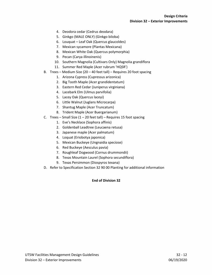
Design Criteria
Division 32 – Exterior Improvements
UTSW Facilities Management Design Guidelines 32 - 12
Division 32 – Exterior Improvements 06/19/2020
4. Deodora cedar (Cedrus deodara)
5. Ginkgo (MALE ONLY) (Ginkgo biloba)
6. Louquat – Leaf Oak (Quercus glaucoldes)
7. Mexican sycamore (Plantas Mexicana)
8. Mexican White Oak (Quercus polymorphia)
9. Pecan (Carya illinoinenis)
10. Southern Magnolia (Cultivars Only) Magnolia grandiflora
11. Summer Red Maple (Acer rubrum ‘HQSR’)
B. Trees – Medium Size (20 – 40 feet tall) – Requires 20 foot spacing
1. Arizona Cypress (Cupressus arizonica)
2. Big Tooth Maple (Acer grandidentatum)
3. Eastern Red Cedar (Juniperus virginiana)
4. Lacebark Elm (Ulmus parvifolia)
5. Lacey Oak (Quercus laceyi)
6. Little Walnut (Juglans Microcarpa)
7. Shantug Maple (Acer Truncatum)
8. Trident Maple (Acer Buergarianum)
C. Trees – Small Size (1 – 20 feet tall) – Requires 15 foot spacing
1. Eve’s Necklace (Sophora affinis)
2. Goldenball Leadtree (Leucaena retusa)
3. Japanese maple (Acer palmatum)
4. Loquat (Eriobotya japonica)
5. Mexican Buckeye (Ungnaidia speciose)
6. Red Buckeye (Aesculus pavia)
7. Roughleaf Dogwood (Cornus drummondii)
8. Texas Mountain Laurel (Sophora secundiflora)
9. Texas Persimmon (Diospyros texana)
D. Refer to Specification Section 32 90 00 Planting for additional information
End of Division 32

Design Criteria
Division 32 – Exterior Improvements
UTSW Facilities Management Design Guidelines 32 - 13
Division 32 – Exterior Improvements 06/19/2020
DOCUMENT HISTORY Issue Date Description Editor
06/19/2020 June 19, 2020 Print EV

Design Criteria
Division 32 – Exterior Improvements
UTSW Facilities Management Design Guidelines 32 - 14
Division 32 – Exterior Improvements 06/19/2020
Blank Page

Design Criteria
Division 33 - Utilities
UTSW Facilities Management Design Guidelines 33 - 1 Division 33 – Utilities 06/19/2020
DESIGN CRITERIA
DIVISION 33
UTILITIES

Design Criteria
Division 33 - Utilities
UTSW Facilities Management Design Guidelines 33 - 2 Division 33 – Utilities 06/19/2020
Blank Page

Design Criteria
Division 33 - Utilities
UTSW Facilities Management Design Guidelines 33 - 3 Division 33 – Utilities 06/19/2020
DIVISION 33 00 00 – UTILITIES
I. General Information
A. All connections to campus utility distribution systems or public utilities shall be
accurately located by dimensions or coordinates. Depth of piping shall be shown and
inverts must be shown at manholes and other critical points.
B. All site utilities shall be included as part of the drawing deliverables. They shall be shown
accurately in terms of size, depth, and location.
C. Locations of utility lines, sleeves and pipes underneath sidewalks, driveways, parking or
other paving shall be permanently marked with utility identification. Utility markers
shall be of brass, stainless steel or other rugged metal drilled and adhered into the
pathway near the perimeter. Markers shall have wording on the top with general
description of items buried as well as arrows indicting direction.
D. Site telephones 1. Provide at least two exterior emergency telephones. Each location shall be ADA
accessible. Contractor to provide one telephone conduit, one power conduit and power line, and foundation with anchor bolts. Conduit shall be one-inch minimum size. Verify exact location with Owner. Comply with campuses standard for emergency telephones.
II. Design Review Submittal Requirements
A. Refer to Sections B, B1 and B2 in the UTSW Design Guidelines
III. Section 33 05 00 Concrete Utility Boxes
A. Concrete boxes required by the mechanical, plumbing, civil site work and/or electrical
divisions must be properly dimensioned, reinforced and/or detailed. Chilled water and
heating water valves in underground systems shall have as an enclosure a concrete
valve box with sufficient space to maintain and operate valves. Direct buried valves may
be considered if acceptable to the System Mechanical Engineer.
IV. Section 33 10 00 Water Utilities
A. The domestic water system shall be designed and installed in accordance with TCEQ
requirements
B. Domestic water piping 4" to 12” shall be AWWA C-900 or AWWA C-909, Class 200 PVC
with elastomeric gasketed push-on joints. Domestic water piping larger than 12” shall be
AWWA C-905, Class 200 PVC with elastomeric gasketed push-on joints. Fittings shall be
cement mortar lined and appropriately coated and protected mechanical joint ductile
iron. Piping smaller than 4" shall be SDR 21 Class 200 ASTM D2241, PVC with
elastomeric gasketed push on joints. Fittings shall be PVC of equal strength.
C. All angles, bends, tees etc. shall be stabilized with concrete thrust blocks sized by the
Project A/E. Appropriately spliced and terminated tracer wire or aluminum tape shall be
laid with all non-metallic water line.
D. Line valves shall be placed at all points of connection to existing water lines, at branch
intersections and any other location necessary for adequate control of the water
system. Typically, the number of valves at an intersection will equal the number of

Design Criteria
Division 33 - Utilities
UTSW Facilities Management Design Guidelines 33 - 4 Division 33 – Utilities 06/19/2020
branches less one. “In line” valves shall be placed in long runs of pipe at approximate
2000-foot spacing. Adequately supported air/vacuum relief valves shall be installed as
required along the main in enclosures to facilitate draining and maintenance/inspection.
E. Line valves 3" and larger shall be direct bury resilient wedge gate valves meeting the
requirements of AWWA C509 with mechanical joint connectors and non-rising stem nut
operator. Valves shall be poly wrapped in accordance with AWWA C105. All valve
operators shall open when turned counterclockwise and close when turned clockwise.
F. Line valves smaller than 3" shall be bronze body ball valves with threaded connectors,
stainless steel ball and stem, lever operated with a rated working pressure of 200 psi.
G. Cast iron adjustable valve boxes with surface reinforced concrete collar shall be
provided over all buried valves to provide access from ground surface to valve operating
nut
H. Adequate fire hydrants shall be placed around the facility such that no portion of the
building is over 300 feet from a hydrant. Fire hydrants shall be 5 1/4" main valve
opening with 2 ~ 2-1/2" hose nozzles and a 4 ½" pumper nozzle. Coordinate nozzle size
and thread requirements with entity providing fire protection. Hydrants shall be drytop
compression type hydrants, traffic model, complying with AWWA C502. Auxiliary gate
valves shall be placed in all hydrant leads.
I. Where necessary, connections to existing water mains shall be a “hot” tap using a
tapping sleeve and valve appropriate to the type of pipe being tapped. No full size taps
shall be made without approval by the Owner.
J. The domestic water supply to a facility shall be metered unless directed otherwise by
the Owner
K. The complete site domestic water system installed for the project shall be pressure
tested for leakage in accordance with TCEQ requirements along with applicable fire
protection codes and shall be disinfected in accordance with the requirements of
AWWA C601.
L. All waterlines shall have an aluminum detector tape placed 12” below final grade
V. Section 33 30 00 Sanitary Sewerage
A. Gravity sanitary sewer mainlines shall be no less than 6" and services lines shall be no
less than 4". All gravity sanitary sewer piping shall be SDR 26 PVC (ASTM D 3034) or
heavier. Exposed piping shall be ductile iron with appropriate coating protection. PVC
and ductile iron piping shall have watertight push-on joints using elastomeric gaskets
meeting the requirements of ASTM F 477 and AWWA C111 respectively. Fittings shall be
of equal strength as the piping. Appropriately spliced and terminated tracer wire or
aluminum tape shall be laid with all non-metallic sewer piping.
B. Manholes are required for all horizontal and vertical bends as well as changes in pipe
size. Manholes on sanitary sewer mainlines shall be spaced no further than 350 feet
apart and be placed at all piping intersections and angle points with the exception of 4"
service lines. Appropriate wye fittings shall be used at such service connections.
Sanitary sewer manholes shall be either cast-in-place or pre-cast (ASTM C478)) with a
reinforced concrete base. Minimum 28-day concrete strength shall be 3,000 psi.
Manholes shall be placed on 9” of 1-1/2 sack cement stabilized sand. The invert of the

Design Criteria
Division 33 - Utilities
UTSW Facilities Management Design Guidelines 33 - 5 Division 33 – Utilities 06/19/2020
manhole shall be sloped and smooth finished sufficiently to prevent deposition of solids.
If the elevation difference between an entering pipe and the existing pipe is more than 2
feet, a drop type connection to the manhole shall be used. Manhole construction and
testing shall be in accordance with TCEQ requirements.
C. Sanitary sewer and storm sewer shall be shown on separate sheets along with profiles.
All pipes penetrating exterior walls or foundations of buildings below grade must be
installed properly with sleeves to prevent breakage due to building settlement or
expansive soil.
D. Provide 30-inch diameter minimum size access openings for all sanitary manholes
E. Cleanouts shall be provided for all service laterals and be located at the building and at
each bend. Cleanouts shall be installed on all 4" sanitary sewer service lines as required
to facilitate line cleaning.
F. Profiles on sewer lines shall be shown for all pipe sizes. The profiles shall show as a
minimum, depth of cover, other utility crossings with verified elevations, slope, inverts,
pipe material and class of pipe.
G. Sanitary sewer lift stations shall consist of precast (ASTM C478) or cast-in place
reinforced concrete wet well containing a heavy-duty duplex pumping system readily
accessible/removable for replacement/maintenance. A lockable hatch system of
adequate size for maintenance/access shall be provided. A reliable level control system
shall be provided to start/stop the pumps including a high level alarm. The basic control
system shall consist of a remote disconnect, combination starter for each motor, H-O-A
switches, visual and audible high level alarm, run lights and seal failure sensors. All
Conduit connections to the wet well will be adequately sealed to sewer gases/moisture.
Pump discharge piping for each pump shall be flanged ductile iron containing a check
valve and plug valve located in a valve pit exterior to the wet well. Metal surfaces inside
the wet well and the inside surfaces of the wet well shall be protected by appropriate
coatings. Valve pit shall have a lockable hatch of adequate size for operation and
maintenance of valves.
H. Sanitary sewer force mains shall be SDR 21 PVC complying with ASTM D2241. All fittings
shall be of equal Class and pressure rating as pipe. All angles, bends, tees, etc. shall be
stabilized with concrete thrust blocks, sized by the Project A/E. All non-metallic force
mains shall have aluminum detector tape 12” placed below final grade.
I. The sanitary sewer system shall be designed, installed and tested in accordance with
Texas Commission on Environmental Quality (TCEQ) requirements. Leakage test on PVC
pipe shall be a low pressure air test performed as set forth by the Uni-Bell PVC Pipe
Association. Deflection tests shall be by a mandrel pulled 30 days following trench
backfill. All tests shall be witnessed by the Owner.
VI. Section 33 40 00 Stormwater Utilities
A. Storm sewer shall either be RCP Class III (ASTM C76) for 12" and above or SDR 26 PVC
(ASTM D3034) or heavier for less than 12". RCP joints shall meet ASTM C443. PVC pipe
shall have water tight push-on joints meeting the requirements of ASTM F477.
B. Storm roof drains shall be run separately from all other storm water sources to the
outside of the building

Design Criteria
Division 33 - Utilities
UTSW Facilities Management Design Guidelines 33 - 6 Division 33 – Utilities 06/19/2020
C. Both sanitary and storm sewers sizes shall be determined by a Texas Professional
Engineer (PE) and is to be based on existing/future sewer capacities and a drainage
study for storm sewers. If the existing infrastructure cannot accommodate the increased
loads, then an estimate shall be presented to the Owner to determine if additional
funds need to be appropriated for any up-sizing.
D. Manholes and/or junction boxes with access openings shall be installed on the storm
sewer system at all piping intersections, changes in slope and angle points with the
exception of small drain leads which may use appropriate wye fittings. Manholes shall
be either pre-cast (ASTM C 478) or cast-in-place with a reinforced concrete foundation.
Junction boxes shall be of reinforced pre-cast or cast-in-place construction. Minimum
28-day concrete strength shall be 3,000 psi. Foundation for manholes and/or junction
boxes shall be on 1-1/2 sack cement stabilized sand.
E. Provide 30-inch diameter minimum size access openings for all manholes. Iron castings
for manhole rings and covers shall conform to ASTM A 48, Class 30 and be traffic rated.
F. Area inlets for the storm sewer system shall be either pre-cast or cast-in-place
reinforced concrete with frame and grate iron castings conforming to ASTM A48 Class
30 and shall be traffic rated. Curb inlets shall also be either pre-cast or cast-in-place with
a manhole frame and cover installed in the top to allow access. In high visibility areas
near buildings or at pedestrian drop off points, inlet tops shall be cast-in-place.
Minimum concrete 28-day compressive strength for inlets shall be 3,000 psi. Typically
storm sewer discharge points shall be stabilized with either a pre-cast or cast-in-place
headwall structure with adequate surrounding rip-rap to control erosion. Minimum
concrete 28-day compressive strength for headwalls shall be 3,000 psi.
VII. Section 33 60 00 Chilled and Heating Water Distribution
A. Chilled water and heating water distribution piping shall be pre-insulated ductile iron.
All straight section shall be factory insulated. Fittings and joints shall be provided with
field insulation kits compatible with the factory insulation. The insulation shall be
protected by an HDPE outer shell. Pipe shall be listed suitable for use with 43-degree
chiller water and 180-degree heating water. Ductile iron pipe shall be Class 50 thickness,
restrained joint conforming to ANSI A 21.512 or AWWA C 151-75.
B. Pipe and fittings shall be cement lined and have an external bituminous/tar coating and
no internal coating. Pipe and fittings shall be U.S. Pipe TR FLEX or Clow Super Lok.
C. Spacing between chilled and heating pipes should be at least 10 – 12 inches
D. Direct burial of steam piping is not acceptable but may be required on some areas of
campus. This is only allowed after review and approval from Utilities group
E. Use Cor-ten© bolts or corrosion resistant alloy bolts on underground piping especially
heating water piping
F. Direct bury of valves is not recommended. Valves shall be located for access within a
vault or manhole.

Design Criteria
Division 33 - Utilities
UTSW Facilities Management Design Guidelines 33 - 7 Division 33 – Utilities 06/19/2020
VIII. Section 33 71 19 Electrical Distribution - Underground Ductbanks
A. Outside the perimeter of buildings, install underground medium-voltage conductors in
red-colored, concrete-encased, steel-reinforced ductbanks with not less than 3-inches
concrete coverage and 1.5 inches between adjacent ducts.
B. Specify red-dyed concrete for medium-voltage ductbank embedment. Dye shall consist
of red ferrous-oxide concrete coloring pigment mixed at the rate of two pounds per sack
of cement.
C. Minimum duct trade size (nominal voltage class):
1. Low-Voltage (0 - 1000 V): 2 inches
2. Medium-Voltage (15kV): 6 inches
D. Specify duct material to be Schedule 40 polyvinyl chloride (PVC)
E. Design ductbanks and manhole systems to slope a minimum of 3 inches per 100 feet to
a suitable sump in a manhole
F. Design ductbanks to provide a minimum cover of 30 inches from the ground surface to
the top of the concrete
G. For new power ductbank installations, provide 33% spare ducts, rounding all fractions
up to the next whole number, but not less than one spare duct
H. For projects involving addition of cable(s) to an existing ductbank, provide a new duct
run along the same route if the installation will fill the only remaining open duct(s)
I. Provide a minimum of two new spare ducts. A fault in a ductbank frequently results in
the faulted cable adhering to the walls of the duct, very difficult or impossible to
remove.
J. Install underground warning tape below grade and above all ductbanks marked “BURIED
ELECTRIC LINE.” Warning tape shall be metallic (detectable) or contain a detection strip
integral to the tape material.
IX. Section 33 71 19.13 Power Manholes
A. Provide precast concrete manholes dedicated to the campus medium-voltage utility and
distribution system. Include all standard hardware and accessories.
B. Provide precast manholes for all site medium voltage power distribution. The maximum
allowed spacing is 400 feet and at all 90º horizontal changes in direction.
C. Medium-voltage manholes used for the distribution of power shall have nominal
dimensions of 8-ft high X 10-ft long X 8-ft wide to accommodate the space required for
pulling, bending, wrapping, and supporting the largest shielded MV105 cables required
for a 600A main feeder circuit consisting of 3-500kcmil conductors plus a 600V-rated 2
AWG grounding conductor, in addition to the largest submersible medium-voltage
switch that may be installed (a unit with 5 switched-ways each rated at 600A).
D. Standard hardware and accessories for power manholes include:
1. Thin-wall knock-outs on every wall
2. Ladder with skid-resistant rungs anchored to floor and wall
3. H-20 rated manhole ring and cover
4. Sump pit & pump
5. “Ladder Up” safety post
6. All metal parts bonded to ground rod

Design Criteria
Division 33 - Utilities
UTSW Facilities Management Design Guidelines 33 - 8 Division 33 – Utilities 06/19/2020
7. Cable racks
8. Pull irons
E. All existing manholes must be kept accessible at all times during construction
X. Section 33 80 00 Data/Telecomm Distribution
A. The contractor shall furnish and install a telecommunications ductbank consisting of 4
four inch conduits surrounded by reinforced concrete similar to the 12KV ductbanks
except the concrete shall not be dyed orange.
B. This duct bank shall include a No. 2/10 bare ground wire cast inside the concrete
envelope. The duct bank shall run from the building’s main telecom room (MDF room)
to the Owner designated telecom manhole.
C. Sand shall not be used as a backfill
D. A minimum of 18 inches of backfill is required but 24 inches is preferred
E. There must be a minimum of 24 inches of cover above the concrete encasement
F. All hand holes shall be traffic rated and large enough to store cable slack without
damaging cable
G. Two of the three ducts must have 3-2 cell flexible fabric inner duct installed
XI. Site Lighting
A. Refer to Division 26 of the UTSW Design Guidelines
XII. Section 33 05 61 Manhole Covers A. UTSW has standardized utility manhole covers shall be conventional cast iron or steel
covers with H-20 & AASHTO HS-25 load rating 1. Provide DOT-rated thickness to be used for vehicular traffic on roadways and
drives 2. Top surface is slip resistant 3. “UTILITIES” to be cast into center of all manholes together with utility
commodity name (ELECTRICAL, THERMALS, SANITARY, STORM) where applicable.
4. No commodity name to be shown on access covers for utility tunnels 5. All covers to be ordered with locking device
End of Division 33

Design Criteria
Division 33 - Utilities
UTSW Facilities Management Design Guidelines 33 - 9 Division 33 – Utilities 06/19/2020
DOCUMENT HISTORY Issue Date Description Editor
06/19/2020 June 19, 2020 Print MDR

Design Criteria
Division 33 - Utilities
UTSW Facilities Management Design Guidelines 33 - 10 Division 33 – Utilities 06/19/2020
Blank Page

Design Process
Section B – Submittal Requirements for Design Documents
UTSW Facilities Management Design Guidelines B - 1 Section B – Submittal Requirements for Design Documents 06/19/2020
DESIGN CRITERIA
SECTION B
SUBMITTAL REQUIREMENTS
FOR DESIGN GUIDELINES

Design Process
Section B – Submittal Requirements for Design Documents
UTSW Facilities Management Design Guidelines B - 2 Section B – Submittal Requirements for Design Documents 06/19/2020
Blank Page

Design Process
Section B – Submittal Requirements for Design Documents
UTSW Facilities Management Design Guidelines B - 3 Section B – Submittal Requirements for Design Documents 06/19/2020
SECTION B – SUBMITTAL REQUIREMENTS FOR DESIGN DOCUMENTS Introduction: Projects at UT Southwestern Medical Center are typically divided up into two main types: Capital Improvement Projects (CIP) and Renovations. This section and its exhibits are applicable to both project types. Architects/Engineers (A/E) shall utilize this section and exhibits in conjunction with the succeeding sections dependent on the project type and scope of the project. The UTSW PM and Procurement shall indicate conformance requirements. UTSW Medical Center provides A/E with standard documents for use and references. As noted in the “General Information” in Section A of the UTSW Facilities Management Design Guidelines, all projects shall confirm to the Design Guidelines. Additional documents to be used on all UTSW projects are listed below. These documents do not relieve the A/E of their professional duties to provide content that is correct, accurate and appropriate for each project. All A/E and their consultants shall participate in reviews, work sessions and presentations where the discipline is involved. These standard documents include:
I. Front End Documents provided by Procurement II. Master Specification sections provided by the UTSW PM
III. UTSW Standard Details provided by the UTSW PM IV. UTSW Self Service Furniture Catalogue for reference provided by the UTSW PM V. UTSW PM to provide any hazardous material report(s)
VI. UTSW PM to provide UTSW Comprehensive Interior Signage Manual and UTSW Comprehensive Garage Signage Manual
VII. UTSW Master Nomenclature List is a forthcoming standing document Deliverables Required for All Projects:
I. Pending Issues Report A. The Project A/E shall prepare, maintain and submit a Pending Issues Report throughout
the Schematic Design, Design Development and Construction Document Phases to record and track outstanding issues, concerns, and decisions for the Design Team. An example may be seen in Exhibit B.1, Pending Issues Report. The example indicates the kinds of data that shall be maintained and documented for pending issues.
II. Drawing Sets shall be provided at each deliverable phase, compiled per discipline and containing index information in PDF format files. Deliverables per phase are detailed in following portions of this document, utilize Section B1 for Capital Improvement Projects and Section B2 for Renovation Projects. At all levels of submission, the A/E will be held to a standard of care for the documents provided to UTSW. All documents submitted shall provide information that is clear, concise, complete and correct.
A. Room numbering shall take place at Design Development Phase and follow UTSW Room Numbering Standard, refer to Section A, Exhibit A.2. All following documents shall use the UTSW room numbers in drawing sets.

Design Process
Section B – Submittal Requirements for Design Documents
UTSW Facilities Management Design Guidelines B - 4 Section B – Submittal Requirements for Design Documents 06/19/2020
III. Project Manual and Specifications shall be provided at each deliverable. Level and details required are noted in each deliverable section. All specifications from outline level to completed document shall follow the most current Construction Specifications Institute (CSI) format, utilizing UTSW Master Specifications as provided by the UTSW PM as well as required. Deliverables shall include compiled PDF with index and word document file formats. Deliverables per phase are detailed in following portions of this document, utilize Section B1 for Capital Improvement Projects and Section B2 for Renovation Projects.
IV. TAS Accessibility Plan Review A. The A/E submits sealed documents to a RAS for an accessibility review. A/E shall send
UTSW PM a copy of the receipt of submittal from the RAS. Refer to Section A – Regulation
Requirements for additional requirements.
B. The A/E shall provide UTSW PM with a corrective action plan to address non-compliant
issues noted in the report while documenting issues in the “Pending Issues Report” seen
in Exhibit B.1.
1. A/E shall identify issues outside of scope and report to UTSW PM
2. A/E shall advise UTSW PM for additional services proposal (ASP) to provide
corrective action plan for issues outside of scope
C. A/E shall review the proposed corrections and potential cost implications with UTSW PM
for approval prior to final documentation. UTSW PM and A/E will determine course of
action to issue updates.
D. The A/E shall document corrections through issuance of documentation such as an ASI or
Addendum to confirm the corrective action plan has been completed.
V. Code Compliance Confirmation Reviews A. The A/E team shall provide “Code Compliance Confirmation Review” and submit to the
UTSW PM at DD and 75% CD submission to ensure the submittals are in compliance with the following codes as they apply to a specific project. During UTSW team’s review after each submittal, OSBC will perform all fire code reviews. Below is a non-inclusive code review list, editions are as listed in sections above:
1. International Building Code (IBC) 2. International Fuel Gas Code (IFGC) 3. International Mechanical Code (IMC) 4. International Plumbing Code (IPC) 5. National Electrical Code (NEC) NFPA 70 6. NFPA 101 Life Safety Code 7. NFPA 1 Fire Code 8. NFPA Codes as applicable, with emphasis on the following:
a. NFPA 101 (including reference documents) b. NFPA 1 (including reference documents)
9. FEMA 100-year flood plain verification 10. Texas Department of Insurance (TDI) First Tier Coastal Counties wind load
criteria B. This Code Compliance Confirmation Review does not relieve the A/E from complying
with the approved codes and standards for the project. See Exhibit C.3 for sample code review template in Section C of the UTSW Design Guidelines

Design Process
Section B – Submittal Requirements for Design Documents
UTSW Facilities Management Design Guidelines B - 5 Section B – Submittal Requirements for Design Documents 06/19/2020
VI. Survey A. A topographic survey will be performed for each project involving new construction and
for FM capital projects where necessary by a surveyor licensed in the State of Texas
B. The survey shall include information for, but not limited to, topography, existing
construction (buildings, roads, sidewalks, etc.), existing utilities on site including closest
point of connection if not on site, significant vegetation, easements, etc.
C. The survey shall be drawn using AutoCAD.
1. The survey shall be modeled at 1:1 scale. All dimensions and elevations shall be
in Imperial units. The plotted scale shall be 1.0” = 20.00’ and the title block shall
include the project name and project number.
2. Include a legend of symbols and abbreviations used on the drawing, a north
arrow and a graphic scale
3. Provide contours at 1 foot intervals unless directed otherwise by the System
Civil Engineer with an error not to exceed 1/2 contour interval
4. Provide at least two horizontal and one vertical control points with description
and elevation to nearest .01'. Datum shall be NAD 83 for horizontal and NGVD
88 for vertical.
5. Provide spot elevations at street intersections and curb, crown of roads,
sidewalks, edge of paving including far side of paving, drainage flow line,
manhole rims/covers, top and bottom of retaining walls, etc. Spot elevation on
paving or other hard surface shall be to the nearest .05’ and spot elevations on
other surfaces to the nearest .1’
6. Include the location of above and below ground structures, man-made and
natural features; all floor elevations and finish floor elevations at each entrance
of buildings on the property, if applicable
7. Include the location, size and depth of water bodies and reservoirs, gas and
thermal utilities. For depths of utilities on UTSW campus, coordinate with the
Facilities Management Department. For depths of utilities in City of Dallas right
of ways, coordinate with City of Dallas.
8. Include the location of fire hydrants available to the property and the size of the
main serving each
9. Include the location and characteristics of power and communications systems
above and below grade
10. Include the locations, size, depth and direction of flow of sanitary sewers,
combination sewers, storm drains and culverts serving or on the property;
location of catch basins, manholes, and inverts of pipe at each.
11. Provide the name of operating authority of each utility. Utility information can
be provided by the Facilities Management Department. Additional information
may also be provided by Facilities Planning Division, Real Estate Services and
Academic Planning
12. Provide the mean elevation of water in any excavation, well, or nearby body of
water
13. Provide the location of 1% annualized potential and 0.2% annualized potential
(100yr & 500-yr) floodplains

Design Process
Section B – Submittal Requirements for Design Documents
UTSW Facilities Management Design Guidelines B - 6 Section B – Submittal Requirements for Design Documents 06/19/2020
14. Provide the extent of watershed onto the property
15. Provide the location of trees along with the species name in English, the caliper
in inches and the canopy width. Provide the perimeter outline only of any
thickly wooded areas unless otherwise directed.
16. Show boundary lines, giving length and bearing (including reference or basis) on
each straight line; interior angles; radius, point of tangency and length of curved
lines.
17. Locate existing benchmarks. Where no monument exists, set permanent iron
pin (monument) or other suitable permanent monument at property corners;
drive pin into ground to prevent movement, mark with wooden stake; state on
the drawing(s) whether corners were found or set and describe each
18. Survey shall be reviewed by UTSW PM and Facilities Management Department
before being finalized
19. The final drawing shall be sealed by a Texas RPLS
20. Upon completion of the survey, provide two copies of the plotted survey and
one DVD or CD-ROM containing the native CAD file, an IFC copy of the file, as
well as an ASCII file of the point elevations. The CD shall be professionally
labeled containing project name and project number. The digital files may be
transmitted electronically in lieu of CDs once confirmed with UTSW PM.
VII. Geotechnical Investigations A. Where geotechnical investigations are required, reports shall be as follows:
1. All parts of the report are to be made on white or off white paper measuring 8
½ x 11 inches, suitable for photocopying and bound in booklet form. If larger
drawings are necessary, they shall be folded to 8 1/2 x 11 inches to fit into the
report booklet.
2. Written reports and analysis shall be on geotechnical firm's letterhead
3. Include with the report a chart illustrating the soils classification criteria and the
terminology and symbols used on the boring logs
4. Identify the ASTM or other recognized standard sampling and test methods
utilized
5. Provide a plot plan with horizontal location and ground elevation of test borings
using same datum as survey
6. Provide vertical sections for each boring plotted and graphically presented
showing the number of borings, sampling method used and date of start and
finish
7. Soil classified in the field logs in accordance with current applicable ASTM and
other standards
8. Surface elevation at all bores
9. Description of soil and thickness of each layer Hydraulic pressure required or
number of blows per foot (N value) and where applicable
10. Depth to loss or gain of drilling fluid
11. Depth to wet cave-in
12. Depth to artesian head

Design Process
Section B – Submittal Requirements for Design Documents
UTSW Facilities Management Design Guidelines B - 7 Section B – Submittal Requirements for Design Documents 06/19/2020
13. Ground water elevation and time when water reading was made (repeat
observation after 24 hours)
14. Presence of gases
15. Location of strata containing organic materials, wet materials or other
inconsistencies that might affect engineering conclusions
16. Description of the existing surface conditions and summarize the subsurface
conditions
17. As a minimum, the following tests are to be performed: Moisture Contents,
Atterberg Limits, Percent Passing #200 Sieve, Hydrometer, Pocket
Penetrometer, Unconfined Compression, and Unit Dry Weight.
B. Two final reports sealed by a Texas Registered Professional Land Surveyor with the
project name and project number on the cover page and one CD-ROM with the report in
Acrobat “PDF” format. The PDF shall contain a Table of Contents linked to the
corresponding pages. The digital files may be transmitted electronically in lieu of CDs.
VIII. Storm Water Pollution Prevention Plan (SWPPP) A. UTSW A/E shall refer to Exhibit B.4 for preparation of SWPPP documents for all sites of
one (1) acre or more
IX. CAD Backgrounds A. The Project A/E shall provide CAD backgrounds at each document review milestone
during Construction Documents. AutoCAD version will be confirmed by UTSW PM. B. All CAD files submitted shall follow UTSW CAD Drafting Standards. Refer to Exhibit B.2 –
UTSW CAD Standards in UTSW Design Guidelines C. All files shall be in root directories with drawing files before support files. Bind all files
to prevent external x-refs
X. Archibus Requirements A. A/E shall provide AutoCAD DWG background that includes rooms, spaces and areas
exported as polylines. Archibus requires polylines to attach to e-handles which contain data and are used in conjunction with the AutoCAD file to create the floor plan graphic visible in the application.
B. Consultants who use drafting programs without conversion procedures inherent to the application should manually populate electronic backgrounds with polylines, prior to sending deliverables to UTSW.
C. Refer to Exhibit B.3 – UTSW Archibus Export Requirements
XI. BIM Requirements A. A/E shall provide BIM files to match UTSW Standards per contract requirements B. Refer to Exhibit B.5 if required

Design Process
Section B – Submittal Requirements for Design Documents
UTSW Facilities Management Design Guidelines B - 8 Section B – Submittal Requirements for Design Documents 06/19/2020
Documentation Format for All Projects: I. All text shall be Arial on floor plans and specifications.
II. Drawing Minimum Requirements: A. Drawing sheets shall be ARCH E1 – 30” x 42” or ARCH D 24” x 36” with project sheet size
being determined with UTSW PM prior to sheet creation. B. Overall plans shall be sized a minimum at 1/8” scale or appropriate scale to fit entire
plan on one page. Enlarged plans a minimum at 1/4” scale. All disciplines shall include room names and numbers on their respective plans.
C. Design Drawings for project area shall fit onto one page. If size is prohibitive, areas may be broken into consecutive pages with matchlines at 1/8” scale minimum.
D. Associated details shall be at larger scales appropriate to view critical components. E. Enlarged plans shall, at a minimum, be created at each: elevation changes (such as
stairs), toilet room, typical room types, electrical rooms, mechanical rooms, IR rooms, and specialty or unique spaces.
III. Backgrounds for all disciplines shall include project grid lines, callouts and any dimensioning that is required to coordinate the project. Structural grids and callouts to match facilities provided CAD plans.
IV. Plan North and Project North arrows and graphic scales shall be shown on each sheet. V. All sheets shall have completed title blocks as noted within “Standard Drawing Set
Requirements for All Projects.” VI. All disciplines shall provide symbols and abbreviations for their work. Sheets shall have general
notes referencing the symbols and abbreviations on that sheet. VII. All disciplines shall provide disclaimers on their work, for each design phase submitted,
indicating interim review. This disclaimer shall include the responsible A/E name, license/registration number and professional designation. Professional seals with signature are required for construction, bidding or permit purposes on all documents produced.
VIII. Design Drawings compiled into one pdf in order to match index numbers and names. If file size is prohibitive to use easily, file may be broken into packages or into disciplines following the order of the index
Standard Drawing Set Requirements for All Projects:
The following items shall be included in each design phase submittal. Cover Sheet: Cover sheet shall include at a minimum:
I. UTSW project name, Work Order number and UTSW PM Name with their contact information II. UTSW project address and/or location
III. Project A/E name and street address with contact name and information. Shall include email address, phone number and fax number.
A. All companies shall be licensed/registered to practice in Texas with the A/E of record to be licensed/registered to practice in Texas.
IV. Project A/E consultants’ names and professional discipline(s) with contact name and information. Shall include email address, phone number and fax number.
V. Project location plan to scale appropriate to building size. VI. List of applicable UTSW building codes

Design Process
Section B – Submittal Requirements for Design Documents
UTSW Facilities Management Design Guidelines B - 9 Section B – Submittal Requirements for Design Documents 06/19/2020
Title Block: A/E shall create a Title block draft to be reviewed with UTSW PM prior to first deliverable. The following items at a minimum shall be included on each drawing title block:
I. UTSW project name, Work Order number and PM name II. UTSW project address and/or location
III. Project A/E name and street address IV. Project A/E consultants’ names and professional discipline(s) on their sheets. V. Location for the date of issue of the plans with space for several revision dates
VI. Location for professional seals and registration numbers VII. Location for the sheet title
VIII. Location for Sheet Name and Number. All sheet number sequences shall be matched by other disciplines. I.e. A1.01 Demolition Plan shall be matched to E1.01, M1.01, etc.
IX. Deliverable Phase Title X. Project Key Map for larger projects shall indicate which project area is indicated on the sheet.
Project Data Sheet: The project data sheet shall include, at a minimum, the following information specific to the project design and the phase of deliverable:
I. List of Drawings, Tables and Schedules II. Square footage per project level and the project total (gross and assignable square footage).
See Section A, Exhibit A.1, Definitions of Building Areas. III. Project information including approximate square feet of space to be renovated/constructed. IV. List of applicable UTSW building codes including codes and standards analysis summary (Can be
submitted as an independent code page) V. Abbreviations used
VI. Drawing symbols VII. Alternate bid descriptions
VIII. Future provisions for expansion (all design disciplines) IX. Materials legend X. Vicinity map
Standard Accessibility Sheet: I. Each project shall have the A/E’s standard sheet(s) demonstrating the TAS 2012 standard
heights, clearances and requirements as references. Shall include knee and toe clearances, clear floor or ground space, protruding objects, stairways, doors and applicable site requirements at a minimum.
Equipment Schedules and Coordination:
I. Equipment Scheduling: Provide equipment scheduling for all equipment requiring a space allocation and/or architectural/mechanical/plumbing/electrical service and/or any rough-in, including any provisions for future equipment if required in the construction documents.
II. Equipment schedules shall be included in deliverables as early as possible but not later than Design Development deliverables. Categories shall include the following at a minimum:
A. Equipment designator B. Equipment Manufacturer, Item number C. Quantity D. L x W x H

Design Process
Section B – Submittal Requirements for Design Documents
UTSW Facilities Management Design Guidelines B - 10 Section B – Submittal Requirements for Design Documents 06/19/2020
E. Required clearances for service, maintenance and/or code F. Utility Requirements (Electrical, water service, gas, grounding, etc.) G. Specification section number H. Special notes I. Furnish/Install assignment
III. Furnish/Install assignment of which entity furnishes the item as well as which entity shall install the item shall follow the following categories:
A. Contractor Furnished - Contractor Installed (CFCI) B. Owner Furnished - Contractor Installed (OFCI) C. Owner Furnished - Owner Installed (OFOI) D. Owner Furnished – Vendor Installed (OFVI)
IV. In all cases, the infrastructure designed by the A/E shall be coordinated to provide for all known pieces of equipment. In some instances, equipment that is more specialized may require utilizing more than just two entities for a complete installation. In these cases, the equipment schedule shall indicate multiple categories, as seen in the next example.
A. Example: A cage wash machine will be purchased by the owner, with the vendor installing the machine. The contractor will be required to perform hard connections to the utilities. While the infrastructure of the building shall inherently be designed to provide for the cage wash, this does not clearly identify the need for electricians or plumbers at installation. This machine shall show the following in the furnish/install column: OFVI / CFCI
Construction Administration and Closeout Requirements for All Projects:
I. Note: Due to security protocols, no zipped or compressed files shall be accepted. II. Some projects may utilize project management software during construction documentation
and construction administration. Version shall be confirmed by UTSW PM. III. Documentation provided in “.pdf” format shall be provided with Optical Text Recognition. IV. Dependent on contract requirements, A/E shall revise the drawings and specifications upon
Final Completion of the construction, to incorporate all Addenda, all Change Orders for the Work and any modifications recorded by the Contractor on the As-Built Drawings and Specifications maintained at the job site. The A/E shall label the revised drawings and specifications as “Record Drawings” and “Record Specifications” and shall deliver copies to the UTSW PM for record purposes, as follows:
V. Record Specifications: Provide one (1) bound hard copy set and one (1) electronic set of the fully conformed records specifications incorporating all changes and as-built conditions on CD or DVD in PDF format.
VI. Record Drawings: Provide one (1) complete bound print set of record drawings, and one (1) complete electronic set of the full record drawings incorporating all changes and as-built conditions on CD or DVD.
VII. Confirm contract requirements: A. CAD files of drawings shall comply with UTSW CAD Standards B. BIM files of project shall comply with UTSW BIM Standards

Design Process
Section B – Submittal Requirements for Design Documents
UTSW Facilities Management Design Guidelines B - 11 Section B – Submittal Requirements for Design Documents 06/19/2020
Office of Safety and Business Continuity (OSBC) Coordination Requirements: Project shop drawing documentation required for review by OSBC shall conform to the following as well
as specific requirements from UTSW Master Specification sections.
Civil: (NFPA 1: 1.7.11.1/ 12.8)
I. New Construction
II. Renovation/ Modification
Architectural / Engineering: (NFPA 1: 1.7.11.5/ 1.7.11.6/ 12.8)
I. New Construction
II. Renovation/ Modification/ Tenant Fit Out
Automatic Fire Sprinkler System: (NFPA 1: 1.7.11.1/ 1.7.11.6/ 12.8; NFPA 13: 23.1)
I. New Installations
II. Renovation/ Modifications/ Tenant Fit Outs which require the addition or movement of
more than 2 sprinkler heads
Hydraulic Calculations
I. Required for the addition or modification of more than 5 fire sprinkler heads
Fire Alarm System: (NFPA 1: 1.7.11.1/ 1.7.11.6/ 12.8; NFPA 72:7.1.1/ 7.1.2)
I. New Installations
II. Renovation/ Modifications/ Tenant Fit Outs which require the addition or movement of
more than 2 fire alarm devices
Battery Calculations
I. Required for the addition or modification of more than 2 devices
Clean Agent System: (NFPA 1: 1.7.11.1/ 1.7.11.6/ 12.8; NFPA 2001: 5.1.2.1)
I. New Installations
II. Renovation/ Modifications/ Tenant Fit Outs which require the addition or modification of
nozzles or fire alarm devices
System Calculations
I. Required for the addition of any nozzles or fire alarm devices
Ansul System: (NFPA 1: 1.7.11.1/ 1.7.11.6/12.8; NFPA 17A: 6.3)
I. New Installations
II. Renovation/ Modifications/ Tenant Fit Outs which require the addition or modification of
nozzles or fire alarm devices

Design Process
Section B – Submittal Requirements for Design Documents
UTSW Facilities Management Design Guidelines B - 12 Section B – Submittal Requirements for Design Documents 06/19/2020
Agent Calculations
I. Required for the addition of any nozzles
Other Plans/ Permits required by the Fire Code:
I. Permits for Tank Installation/ Removal or for Change of: Occupancy; Means of Egress; Fire
Suppression; Fire Alarm; Private Fire Hydrants; Open Fires/ Burning; Tents; Hot Works;
Construction; Etc.
A. NFPA 1: 1.12.2.1 – Applications for permits shall be accompanied by such data as
required by the AHJ and fees as required by the jurisdiction.
B. NFPA 1:12.8 – Permits shall be required in accordance with Table 1.12.8 (a) – (d)
New Construction:
I. NFPA 1:1.7.11.1 – The AHJ shall have the authority to require plans and specifications to
ensure compliance with the applicable codes and standards. (Note: OSBC is the AHJ on
UTSW campus).
Existing Construction:
I. NFPA 1: 1.7.11.6 – Plans shall be submitted to the AHJ proper to the alteration of the means
of egress of fire protections systems of any existing structure.

Design Process Section B – Submittal Documents for Design Documents
UTSW Facilities Management Design Guidelines B - 13 Section B – Submittal Requirements for Design Documents 06/19/2020
EXHIBIT B.1 PENDING ISSUES REPORT
(EXAMPLE)
PROJECT NAME
INSTITUTION NAME
UTSW PROJECT NUMBER
Action Date Requested Requested Responsible Due Date Action Item/Comment Status
Number Action By Action Party for (Open/
Initiated Resolution Closed)
01 09/01/18 A/E Chemical storage list/quantities Institution 10/01/00 Per 50% CD review meeting Open
02 09/01/18 Institution Upgrade Roof warranty CM 10/01/00 Per 50% CD review meeting Accepted
– 9/15/00

Design Process
Section B – Submittal Documents for Design Documents
UTSW Facilities Management Design Guidelines B - 14 Section B – Submittal Requirements for Design Documents 06/19/2020
EXHIBIT B.2 UTSW CAD STANDARDS
I. Requirements
A. The following items must be accurate for acceptance of the files submitted into the UTSW
Renovations department record documents:
B. All lines indicating objects (walls, doors, windows, etc.) must be continuous lines and not
made up of partial lines or duplicated lines.
C. Walls must match architectural conditions as found in the field. Specifically, walls must
meet the exterior walls at mullions, not simply end into a window.
D. If any special conditions found in the field must be noted along with the drawing file at
the time of submittal for review by UTSW Renovations.
E. Layers as shown below are to be maintained and limited to only those layers listed. Any
variance from this list requires prior written approval from UTSW Renovations.
ITEMS ON FACILITY PLAN LAYER NAME
BUILT-IN EQUIPMENT A-EQUP
BUILT-IN EQUIPMENT A-EQUP-HIDN
CABINETS A-CABT
DOORS A-DOOR
DRAWING TITLE / NORTH ARROW TITLE
FUME HOODS A-HOOD
FURNITURE A-FURN-HIDN
PERMANENT WALLS A-WALL-PERM
ROOM NUMBERS A-ROOM-IDEN
SCALE TITLE
SHELVES A-CABT-UPPR
SINKS A-FIXT
STRUCTURAL ELEMENTS S-COL
STRUCTURAL GRID S-COL-GRID
STRUCTURAL IDENTIFICATION S-COL-IDEN
WALLS A-WALL
WINDOWS A-WIND

Design Process
Section B – Submittal Documents for Design Documents
UTSW Facilities Management Design Guidelines B - 15 Section B – Submittal Requirements for Design Documents 06/19/2020
EXHIBIT B.3 UTSW ARCHIBUS EXPORT REQUIREMENTS
I. Deliverables
A. Project deliverables must include an AutoCAD background with rooms, spaces, and areas exported as polylines for use by Archibus. Archibus requires polylines to attach e-handles which contain data and are used in conjunction with the AutoCAD file to create the floor plan graphic visible in the application.
B. Drafting programs used by an A/E without conversion procedures inherent to the application should manually populate electronic backgrounds with polylines prior to sending deliverables to UTSW PM
C. The DWG export setup for REVIT is included but similar procedures exist in AutoCAD Architecture (3-D CAD) as well as other applications
II. Revit Example A. Revit Detail Level: Change to “coarse” to limit the visibility of components, prior to
DWG export. B. Detail Level: Structural framing changes depending on the detail level. At coarse levels,
it appears as lines. At medium and fine levels, it displays with more geometry. C. Manage Visibility Graphics: Do not show detail lines of geometry and/or components.
D. Polylines are not shown for clarity in following images
DWG Export: Acceptable

Design Process
Section B – Submittal Documents for Design Documents
UTSW Facilities Management Design Guidelines B - 16 Section B – Submittal Requirements for Design Documents 06/19/2020
EXHIBIT B.3 (continued)
DWG Export: Unacceptable
E. Revit Detail Level: Change to “coarse” to limit the visibility of components, prior to DWG export.
F. Within the Revit DWG Export option box, choose the CAD Format from the “Select Export Setup.”
1. Select "General" tab and check the box for "Export rooms, spaces and areas as polylines"
2. Under the “Default Export Options” check the box for "Export views on sheets and links as external references"
3. Unless told otherwise, choose AutoCAD 2013under the “export to file format”

Design Process
Section B – Submittal Documents for Design Documents
UTSW Facilities Management Design Guidelines B - 17 Section B – Submittal Requirements for Design Documents 06/19/2020
EXHIBIT B.3 (continued)
Revit Dialogue Box

Design Process
Section B – Submittal Documents for Design Documents
UTSW Facilities Management Design Guidelines B - 18 Section B – Submittal Requirements for Design Documents 06/19/2020
EXHIBIT B.4 Storm Water Pollution Prevention Plan (SWPPP) Deliverables
I. General Requirements
A. The A/E Civil Engineer (CE) is required to visit the site, in person, to evaluate the existing
conditions before preparation of the SWPPP. The CE shall notify the UTSW PM at least
ten (10) business days in advance of site visit. The Owner may choose to participate in
the site review. After visiting the site, the CE shall prepare the SWPPP book to include
the sections listed below.
B. The SWPPP is more than just a SWPPP drawing. A SWPPP book containing all the
relevant SWPPP information for that project is to be maintained at the project site.
C. This A/E guideline must be used in conjunction with UTSW Specification Section 01 57
23, Temporary Storm Water Pollution Control.
II. SWPPP Book Format
A. As a minimum, one digital submission and two hard copies of the SWPPP book (one for
UTSW headquarters, and one for jobsite) shall be prepared in the following format: 8-
1/2” x 11” size paper bound in a 3-ring binder, 1 ½”minimum, with table of contents,
tabbed sections as described below, and with plan drawings (size and scale may vary
depending on nature of project) folded and inserted.
B. The binder is to include a cover page and spine insert on the outside of the binder
indicating the title Storm Water Pollution Prevention Plan, the institution name, the
UTSW project name and number, the consultant’s name and date prepared (month and
year).
III. Title Page, Engineer’s Seal, Signature And Date
A. First page of SWPPP book shall identify the title Storm Water Pollution Prevention Plan,
the institution name, the UTSW project name and number, the consultant’s name and
date (month and year) of preparation of SWPPP. Following identification of the project
shall be the project engineer’s seal, signature and date.
IV. Table Of Contents
A. Include a table of contents in the SWPPP listing all ten (10) of the following Sections
V. Section 1 - Notices Of Intent (NOIs) And Permits Or Construction Site Notices (CSNs) For
Owner And Contractor and Notice of Termination (NOTs)
A. Draft versions of the SWPPP book shall include the incomplete unsigned NOI, CSN or
NOT forms following the Table of Contents. After filing NOIs for Owner and Contractor,
Owner shall distribute both completed and signed NOIs or CSNs for each copy of the
SWPPP book, along with both copies of TCEQ TPEDES Construction Discharge Permits.
VI. Section 2 –Posting Notice/Contacts And Delegation Letters
A. For large construction sites of five (5) acres or larger include two (2) incomplete copies
of the UTSW Posting Notice/Primary Points of Contacts form. Both forms will be
completed later and posted at the entrance of the facility.
B. A copy of the Owner’s and Contractor’s delegation of authority letters are to be kept in
this section
1. Shared SWPPP Acceptance Certification

Design Process
Section B – Submittal Documents for Design Documents
UTSW Facilities Management Design Guidelines B - 19 Section B – Submittal Requirements for Design Documents 06/19/2020
EXHIBIT B.4 (continued) VII. Section 3 – Site Description
A. This section of the SWPPP shall include a written description of the following items or
map when appropriate:
1. A description of the project site, followed by an 8-1/2” x 11” vicinity map. The
vicinity map shall be of sufficient scale to show the project site location and the
major streets and highways in and around the project location.
2. A description of the nature of the project including impacts to other elements
and any environmental impacts
3. Latitude and longitude of the site
4. A description of the intended sequence of major activities that disturb soils for
major portions of the site (e.g., on-site mobilization, demolition, clearing,
grubbing, excavation, grading, utilities and infrastructure installation.). Include
timing of activities when it becomes available.
5. Estimates of the total number of acres of the campus and the total area of the
site that is expected to be disturbed by excavation, grading, or other activities
including off-site borrow and fill areas.
6. An estimate of the runoff coefficient of the site for both the pre-construction
and post-construction conditions and data describing the soil or the quality of
any discharge from the site
7. The name of receiving waters and extent of wetlands
8. Identify any industrial activities such as concrete or asphalt batch plants
associated with the construction of the project. If none, state so.
9. A general location map or vicinity map (e.g. a portion of a city or county map),
which locates the site within the overall drainage pattern of the city and/or
county and shows the receiving waters and surface waters. The preference for
the general location map is a color US Geological Survey Quadrangle map or
equal. An 8 ½” x 11” general location map should be kept in this section or a
larger quad map in the back of the 3 ring binder with other SWPPP drawings in
the section titled exhibits.
VIII. Section 4 – General Permit Requirements
A. Copy of the permit requirements. Include copy of TCEQ TPDES General Permit
TXR150000, March 5, 2013 containing the general permit requirements
IX. Section 5 – Erosion And Sedimentation Controls
A. Each SWPPP shall include a written description of appropriate control measures (i.e.
Best Management Practices - BMPs) that will be implemented as part of the
construction activity to control pollutants in storm water discharges. The written
description must clearly describe for each major activity, appropriate control measures
and the general timing (or sequence) during the construction process that the measures
will be implemented.
B. Include an Erosion and Sediment Control Drawing and any control detail drawings
illustrating the BMPs as exhibits in Section 10. Ensure the proposed locations of
stabilized construction entrances and exits are shown on the Erosion and Sediment

Design Process
Section B – Submittal Documents for Design Documents
UTSW Facilities Management Design Guidelines B - 20 Section B – Submittal Requirements for Design Documents 06/19/2020
EXHIBIT B.4 (continued) Control Drawing (see Section 10 of the A/E Guideline for additional contents of the
drawing).
C. Include a statement identifying which permittee is responsible for implementation.
D. Include statements for Erosion and Sediment Controls - Short and Long Term Goals and
Criteria that include the following:
1. The construction-phase erosion and sediment controls should be designed to
retain sediment on site to the extent practicable.
2. All control measures must be properly selected, installed and maintained in
accordance with the manufacturer's specifications and good engineering
practices. If periodic inspections or other information indicates a control has
been used inappropriately, or incorrectly, the permittee must replace or modify
the control for site situations.
3. If sediment escapes the construction site, off-site accumulations of sediment
must be removed at a frequency sufficient to minimize offsite impacts. (i.e.
sediment accumulation in streets and curbs)
4. Sediment must be removed from sediment traps or sedimentation ponds when
the design capacity has been reduced by 50%.
5. Litter, construction debris, and construction chemicals exposed to storm water
shall be prevented from becoming a pollutant source for storm water discharges
(i.e. screening outfalls, picked up daily) Stabilization Practices – include a
description of interim and permanent stabilization practices for the project site,
including a schedule of when the practices will be implemented. Site plans
should ensure that existing vegetation is preserved where attainable and that
disturbed portions of the site are stabilized. Use of impervious surfaces for
stabilization should be avoided. Stabilization practices may include, but are not
limited to:
a. Establishment of temporary vegetation
b. Establishment of permanent vegetation
c. Mulching
d. Geotextiles
e. Sod stabilization
f. Vegetative buffer strips
g. Protection of trees
h. Preservation of mature vegetation
6. Structural Practices – include a description of structural practices to divert flows
from exposed soils, store flows, or otherwise limit runoff and the discharge of
pollutants from exposed areas of the site to the degree attainable. Structural
practices may include, but are not limited to:
a. Silt fences
b. Earth dikes
c. Drainage swales
d. Sediment traps
e. Check dams

Design Process
Section B – Submittal Documents for Design Documents
UTSW Facilities Management Design Guidelines B - 21 Section B – Submittal Requirements for Design Documents 06/19/2020
EXHIBIT B.4 (continued) f. Subsurface drains
g. Pipe slope drains
h. Level spreaders
i. Storm drain inlet protection
j. Rock outlet protection
k. Reinforced soil retaining systems
l. Gabions
m. Temporary and permanent sediment basins (detention ponds)
n. Stabilized construction exit
o. Rock berms
X. Section 6 – Maintenance
A. As a minimum, include a statement indicating that if site inspections identify BMPs that
are not operating effectively, maintenance shall be performed before the next
anticipated storm event or as necessary to maintain the continued effectiveness of
storm water controls.
XI. Section 7 – Spill Prevention
1. List and describe the material management practices that will be used to reduce the
risk of spills or other accidental exposure of materials and substances to storm water
runoff. The general construction site superintendent is responsible for cleaning up
and disposition of spills.
2. Include a statement that spills and releases of hazardous material shall be reported to
the UT Southwestern OSBC , as soon as there is knowledge of the spill. The OSBC
Environmental Compliance Manager will determine if the spill is a reportable quantity
and determine who must be notified. Include a statement that the contractor shall
contain the spill until such time the OSBC can give direction or clean up.
3. Include a statement that the SWPPP must be modified within 14 days of the spill to
show any BMP modifications for spill prevention
4. Section 8 – Inspections
a. Note to CE: Construction site “owned” by GC and responsibility of
UTSW PM to make sure GC is being monitored to appropriately manage
SWPPP process and any permits. This includes dumpsters.
5. Include in the SWPPP a written description of all steps to be taken, by a qualified
person, to perform inspections of site controls. Steps include, but are not necessarily
limited to items b. through h. below.
6. Include statements that the owner and contractor’s construction inspector shall be
responsible for a routine inspection of on-site controls, once every seven (7) days, on
Tuesday. One standard UTSW form shall be used for routine inspections. An after-rain
event inspection will not be required if the 7 day inspection is followed.
7. Include instructions to perform site inspections, at specified intervals and using UTSW
inspection forms. Verify that all implemented site controls are functioning properly to
prevent erosion and sedimentation. Note any and all deficiencies in site controls on
inspection form. Inspection report forms are to be signed in accordance with the

Design Process
Section B – Submittal Documents for Design Documents
UTSW Facilities Management Design Guidelines B - 22 Section B – Submittal Requirements for Design Documents 06/19/2020
EXHIBIT B.4 (continued) General Permit by a person qualified to make such inspections and by the individual
designated as having certification authority.
B. Include instructions to provide a copy of inspection report to party responsible for
maintenance and repair of site controls. Keep copies of all inspection reports filed with
SWPPP on site for review by EPA, TCEQ, MS4 operator officials, or Owner’s
representatives.
C. Include instructions requiring when controls are found to be ineffective, or require
modification to adequately prevent erosion and sedimentation, revise on-site copy of
SWPPP to reflect changes made. Describe and illustrate change and note date of
change.
D. Direct Contractor to perform regular inspections at beginning of workweek (Tuesday) to
allow sufficient time for maintenance and repair of site controls during same workweek
E. Include instructions that all inspection reports, along with noted revisions to the SWPPP,
shall be retained for a period of at least three years from the date the site is finally
stabilized. Include copy of UTSW SWPPP Inspection Report Form. These forms are to be
duplicated and used for inspection purposes.
XII. Section 9 – Non-Storm Water Discharges
A. Include an inventory of the non-storm water substances expected to be present onsite
during construction. Examples are:
1. Discharges from fire fighting
2. Fire hydrant flushing
3. Vehicle, building and pavement wash water
4. Water used for dust control
B. If no non-storm water substances are expected, then include a statement indicating
there are none
XIII. Section 10 - Exhibits
A. Erosion and Sediment Control Drawing (SWPPP drawing) – plan drawing(s) and detailed
drawing of controls, with plan sheet showing proposed improvements (building, paving,
etc.) and indicating the following:
1. Existing drainage patterns indicated with post construction arrows to show
direction of flow on site with destinations of flow described (both on-site and
off-site destinations)
2. Approximate slopes anticipated after major grading activities (steeper slopes
shall require additional control measures until final stabilization)
3. Areas of soil disturbance (limit disturbance as much as possible and protect as
much of existing vegetation in place as possible)
4. Areas which will not be disturbed (indicate intent to protect or preserve existing
vegetation)
5. Show limits of construction
6. Locations of major structural and non-structural controls identified in SWPPP
(silt fences, berms, swales, dikes, inlet protection, etc)
7. Locations where stabilization practices are expected to occur (exposed
embankments during excavations, etc.)

Design Process
Section B – Submittal Documents for Design Documents
UTSW Facilities Management Design Guidelines B - 23 Section B – Submittal Requirements for Design Documents 06/19/2020
EXHIBIT B.4 (continued) 8. Locations of off-site material, waste, borrow or equipment storage areas
(concrete wash pits, lay-down areas, soil stockpile areas, etc.)
9. Surface waters (including wetlands or low areas, drainage channels, creeks,
lakes, etc.)
10. Locations where storm water discharges to surface water
11. Location and description of any discharge associated with industrial activity
other than construction, including storm water discharges from dedicated
asphalt plants and dedicated concrete plants, which is covered by this permit.
12. Offsite material storage areas (also including overburden and stockpiles of dirt,
borrow areas, etc.) used solely by the permitted project are considered a part of
the project and shall be addressed in the SWPPP
B. General Location Map (Quadrangle Map or equal)

Design Process
Section B – Submittal Documents for Design Documents
UTSW Facilities Management Design Guidelines B - 24 Section B – Submittal Requirements for Design Documents 06/19/2020
EXHIBIT B.5 UTSW BIM STANDARDS
I. General
A. Refer to the Owner’s Design Guidelines issued for the project for other requirements
related to the development, maintenance and exchange of design information, the
formatting of design documents, and the completion and submittal of Record
Documents
B. Refer to Owner’s Master Construction Specifications for other requirements related to
the development, maintenance and exchange of construction project information, and
the completion and submittal of Record Documents.
II. Summary
A. This document establishes general and administrative requirements pertaining to
Building Information Modeling (BIM) to meet UTSW’s expectations for projects of
various sizes and delivered under various contracting methodologies.
B. BIM practices require cooperation and involvement of all parties throughout the project
delivery process, regardless of the delivery method being used for a given project.
C. BIM practices encompass and coordinate traditionally separate functions of design and
construction in order to assemble all related building information into one Project
Information Matrix that will provide the information needed to efficiently operate and
maintain the facility once Substantial Completion has been achieved and the Project has
been turned over to the Owner.
D. It is of primary concern that all building modeling and facility information developed
during the design and construction of the Project be timely and efficiently developed,
maintained and exchanged from initiation of the Project through Final Completion in
accord with all Contract Documents and with Owner's operational and maintenance
needs. Throughout the Project lifecycle, the A/E and the Contractor are expected to
systematically demonstrate to the Owner that all building and system information is
current to the extent that it can be at a given time during the design and construction
process.
E. It shall be the responsibility of the A/E, and each of its consultants, and the Contractor
and each of its Subcontractors, to have or obtain, at their cost, the trained personnel,
hardware, and software necessary to successfully fulfill their respective obligations as
set forth in the mutually developed BIM Execution Plan.
III. Definitions
F. BIM Execution Plan (BEP) – A document developed by the BIM Team that prescribes
how Building Information Modeling will be implemented for the Project and how
requisite information will be transferred into the Project Information Matrix prior to
Substantial Completion of the Project.
G. BIM Level – The extent to which model and information development will be
required on a specific project. The BIM Level initially will be determined by Owner but
may be adjusted, with Owner’s express approval, by the BIM Team over the course of
the Project. The BIM Level will depend upon several factors, including the scope of

Design Process
Section B – Submittal Documents for Design Documents
UTSW Facilities Management Design Guidelines B - 25 Section B – Submittal Requirements for Design Documents 06/19/2020
EXHIBIT B.5 (continued)
project, project schedule; project cost; availability of existing BIM models; and
availability of existing BIM data, etc.
H. Building Automation System (BAS) – The distributed control system that is used to
monitor and control infrastructure systems within its facilities.
I. Building Information Modeling (BIM) – The process of generating and managing building
data using three-dimensional (3-D), real-time, dynamic building modeling software
resulting in a Building Model.
J. Building Information Modeling Team (BIM Team): Working group made up of
representative(s) from the A/E, A/E’s consultants, Contractor, Subcontractors and
Owner. A/E will provide ad hoc representation of the A/E’s consultants on the BIM Team
as required for the implementation of the BIM Execution Plan. Contractor will provide ad
hoc representation of Subcontractors on the BIM Team as required for implementation
of the BIM Execution Plan.
K. Building Model – A 3-D digital representation of physical and functional characteristics
of a facility, or the components or systems thereof that encompass building geometry,
spatial relationships and quantities and properties of building components and systems.
L. Computerized Maintenance Management System (CMMS) – The computer software
package that is used to manage a digital database of information related to its facilities
equipment and systems for the purpose of optimizing its maintenance operations.
M. CMMS Integration Process (CIP) – The prescribed process by which the information
generated during Building Information Modeling will be fully integrated into Owner’s
CMMS. The CIP is to be developed by the BIM Team and is to be included in the BIM
Execution Plan.
N. Construction Documents – In addition to the items set forth in the UTUGCs, the
Construction Documents shall include the Building Model and the Project Information
Matrix.
O. Construction Model – A 3-D digital representation of physical and functional
characteristics of a facility, or the components or systems thereof, that encompasses
building geometry, spatial relationships and quantities and properties of building
components and systems and that is developed by the Contractor or one of its
Subcontractors before or during the Construction Phase of the Project.
P. Design Model – A 3-D digital representation of physical and functional characteristics of
a facility, or the components or systems thereof, that encompasses building geometry,
spatial relationships and quantities and properties of building components and systems
and that is developed during the preconstruction (Design) phase of the Project.
Q. Facilities Information Management (FIM) – The process of gathering, maintaining and
distributing data associated with Owner’s facilities for the purposes of operating and
maintaining those facilities.
R. Level of Development – The degree to which information included within the Building
Model can be relied upon.

Design Process
Section B – Submittal Documents for Design Documents
UTSW Facilities Management Design Guidelines B - 26 Section B – Submittal Requirements for Design Documents 06/19/2020
EXHIBIT B.5 (continued) S. Project Information Matrix (PIM) – The electronic file for a spreadsheet or database that
identifies the information required from the Building Model, Drawings, and any other
data source(s) developed for the Project and the parameters and properties of the
content. During the design phase, the A/E will populate the PIM as information becomes
available. Throughout the construction phase, the Contractor will update the PIM and will
issue scheduled renditions during construction in addition to the final PIM to UTSW at
Substantial Completion of the Project.
T. Record Documents – The electronic files, hard copy drawings, hard copy submittals, RFI’s,
ASI’s and all other forms of documentation that are required to represent the final AS
BUILT condition of the project. Reference the Owner’s Design Guidelines for details and
requirements for this record documentation including CAD Standards.
U. System – A group or collection of items or equipment that work together or in tandem to
function as a whole. Examples of systems include but are not limited to: HVAC systems,
Bulk Gas Systems (any gases or vacuum not supplied by a point-of-service device),
Plumbing, Fire Rated Assemblies such as doors/frames, Glazing, etc or any items that are
commonly known as systems by the Design and Construction Industries. If uncertainty
exists, Consultants and contractor are to coordinate with the owner for clarification.
V. Test, Adjust, and Balance (TAB) Firm: The Owner may engage a Test, Adjust, and Balance
Firm for the Project under a Separate Contract. When engaged for the Project, the TAB
Firm shall be a part of the BIM Team and shall provide services as set forth in the
Specifications and its Separate Contract.
IV. Coordination
A. BIM Team
1. Representatives assigned by Owner’s Designated Representative,
2. A/E, including A/E and sub-consultant BIM manager(s), except for projects
implemented with design-build methodology,
3. TAB Firm, when engaged for the Project.
B. Contractor’s Members
1. Individuals, each having authority to act on behalf of the entity they represent,
explicitly organized to implement all BIM and FIM activities through coordinated
actions.
2. Representatives of Contractor, including but not limited to

Design Process
Section B – Submittal Documents for Design Documents
UTSW Facilities Management Design Guidelines B - 27 Section B – Submittal Requirements for Design Documents 06/19/2020
EXHIBIT B.5 (continued)
a. Contractor’s project manager,
b. Contractors BIM Coordinator
c. A/E, including A/E sub-consultant BIM manager(s), (for projects
implemented with design-build methodology)
d. Subcontractors, as needed for Contractor to fulfill its BIM obligations,
and
e. Equipment suppliers, as needed for Contractor to fulfill its BIM
obligations
C. Scheduling
1. Design (Preconstruction) Phase
a. For projects implemented using the competitive sealed proposal,
construction manager-at-risk, or job order contracting methodology,
the A/E shall integrate all BIM activities into its Project Work Plan and
the design schedule.
b. For projects implemented using the construction manager-at-risk or
design- build methodology, the Contractor shall integrate all BIM
activities into the Baseline Schedule and the Work Progress Schedule
and shall ensure that BIM requirements are clearly set forth in all
solicitation documents used to select subcontractors or suppliers for the
Project. All parties will address scheduling problems and make
necessary notifications in a timely manner to expedite all BIM activities.
2. Construction Phase
a. Contractor shall integrate all BIM activities into the Baseline Schedule
and the work Progress Schedule. All parties will address scheduling
problems and make necessary notifications in a timely manner to
expedite all BIM activities.
b. Contractor shall provide the initial schedule of primary BIM activities at
the project kick-off meeting. Prior to the start of Schematic Design,
Contractor shall have incorporated and integrated all BIM activities into
the Baseline Schedule and Work Progress Schedule with appropriately
linked predecessors and successors.
D. Roles and Responsibilities
1. Roles and responsibilities of BIM Team members are set forth below to help to
clarify Owner’s expectations with respect to the BIM and FIM processes.
2. Owner’s Role and Responsibilities:
a. Provide specifications related to the format and content for the Project
Information Matrix.

Design Process
Section B – Submittal Documents for Design Documents
UTSW Facilities Management Design Guidelines B - 28 Section B – Submittal Requirements for Design Documents 06/19/2020
EXHIBIT B.5 (continued)
b. Provide initial direction as to the extent the BIM is to be used on the
Project. BIM Level to be used on the Project.
c. Approve the BIM Execution Plan and A/E’s and Contractor’s schedules for
completing all BIM activities.
d. Participate in BIM Team meetings.
e. Review and validate adequacy of Building Model development and
project data collection.
3. A/E’s Role and Responsibilities:
a. Attend BIM Team meetings.
b. Incorporate all BIM activities into the design Work Plan and the design
phase schedule.
c. Produce for Owner’s approval, the initial BIM Execution Plan, the initial
Project Information Matrix of all devices, systems and equipment
supplied.
d. Review and approve Contractor’s edits to the BIM Execution Plan, and
the Project Information Matrix.
4. Contractor’s Role and Responsibilities:
a. Receive from A/E and assume lead responsibility for the BIM Execution
Plan, the Building Model and the Project Information Matrix.
b. Administer updates to the BIM Execution Plan, the Building Model and
the Project Information Matrix with the intent that all BIM-FIM Team
members will have up-to-date information as the Project progresses.
c. Provide an individual, subject to Owner’s approval, experienced in
Building Information Modeling to document changes to Building Model
and complete the implementation of the BIM Execution Plan. The
Contractor shall assign this individual to act as the BIM Coordinator, who
may have additional duties such as MEP Coordinator, but shall not be
Contractor’s project manager or superintendent. Contractor shall submit
qualifications demonstrating the BIM Coordinator’s technical expertise
and experience to the Owner for approval. In the event that Contractor
chooses to subcontract its BIM obligations, Contractor must submit the
name and qualifications of the proposed subcontractor for Owner’s
approval.
d. Ensure that Building Modeling activities are incorporated into the
Baseline Schedule and the Work Progress Schedule.
e. Schedule and conduct periodic meetings with Subcontractors and
equipment suppliers related to BIM to ensure the Building Model and
the Project Information Matrix are being routinely and accurately
updated.

Design Process
Section B – Submittal Documents for Design Documents
UTSW Facilities Management Design Guidelines B - 29 Section B – Submittal Requirements for Design Documents 06/19/2020
EXHIBIT B.5 (continued)
V. PART 2- EXECUTION
A. BIM EXECUTION PLAN
1. Throughout its development, efforts shall be made to align the responsibilities
set forth in the BIM Execution Plan with the skills customarily contributed by
each party associated with the Project. The BIM Execution Plan shall be
considered as a “living document” that is to be updated and refined
throughout the life of the Project and shall be available for review and
verification by Owner at any time.
2. To the extent practical, the BIM Execution Plan shall minimize redundant efforts
in favor of a single, organized approach to all activities required to successfully
complete the BIM- FIM process.
3. The BIM Execution Plan shall include all pertinent Project Information, as a
baseline for required information, reference the “BIM Project Execution
Planning Guide” created by the CIC Research Group, Department of
Architectural Engineering, and The Pennsylvania State University. It shall also
identify and specify;
a. the extent to which Building Model(s) are to be used on the Project.
b. the expected timeline for when information will become available.
c. the information workflow process, which is to include identifying from
where the information to be included in the PIM will originate, the
requirements for transferring information from and to each model and
into the PIM, the Depth of Detail and the party responsible for
authoring and supplying the information at the appropriate time.
d. the version of the Autodesk Building Design Ultimate software suite
into to which the project documents will be transferred.
e. the file structure for the Building Model.
f. all model types, names, content and relationships.
g. the Level of Development for each element to be included within the
Building Model at each stage of the Building Model development.
h. the Depth of Detail for each element to be included within the Building
Model.
i. the drawings to be generated from the Building Model(s) and the
process(es) to be used for generating two-dimensional drawings from
the Building Model(s) to ensure that all generated drawings adhere to
Owner’s CAD standards drawing structure, content, data elements and
delivery as defined in the Owner’s Design Guidelines.
j. the CMMS Integration Process to be used on the Project, including
the requisite process for receiving Owner’s CMMS Asset Numbers and
for incorporating those numbers into the design documents and the
PIM.
k. the data transfer protocol.

Design Process
Section B – Submittal Documents for Design Documents
UTSW Facilities Management Design Guidelines B - 30 Section B – Submittal Requirements for Design Documents 06/19/2020
EXHIBIT B.5 (continued) l. conventions to be used for naming files.
m. measures to be taken to ensure that there is no significant loss of
drawing entities or data during drawing generation and data extraction.
n. areas in which laser scanning is to be conducted.
4. Development of the BIM Execution Plan shall be included as an agenda item for
all Project Team meetings throughout the Preconstruction (Design) Phase of the
Project. As and when appropriate, the discussion items shall include, as a
minimum;
a. the status of the development of the BIM Execution Plan,
b. the identification of any issues related to the timing for exchanging
information between the various Building Models and the timing and
the means and methods for entering information into the Project
Information Matrix,
c. the Level of Development of each of the Building Models,
d. the Depth of Detail for information within the Building Models and to be
entered into the Project Information Matrix.
B. EXTRACTED DATABASE
1. Unless Owner specifically agrees otherwise, all data input into the model(s) or
CAD drawings shall be extracted from its various sources and delivered in a
single Microsoft Access database. This Extracted Database shall include:
a. equipment data gathered during the course of design and construction
that is related to equipment listed in the PIM, but for which a data field
does not exist within the PIM. This data may or may not physically
reside with a table or schedule located within the drawings or
specifications.
b. fixed equipment data gathered during the course of design and
construction that is not associated with equipment listed in the PIM
(e.g. manufacturer’s maintenance information related to sinks, faucets,
emergency showers, light fixtures, life safety items, etc.). This data may
or may not physically reside with a table or schedule located within the
drawings or specifications.
c. data related to all fixed architectural and finish features (e.g.
manufacturers maintenance information related to doors, hardware,
finishes, glazing, etc.). This data may or may not physically reside with a
table or schedule located within the drawings or specifications.
d. all information that is contained within a schedule or table located
within the drawings.
e. all information contained within a schedule or table within the
specifications.
C. DOCUMENT INDEX
1. An index shall be included with each document delivery. The document index
shall be in the form of a Microsoft Excel spreadsheet and shall identify every file
included in the delivery. Identification information shall include;

Design Process
Section B – Submittal Documents for Design Documents
UTSW Facilities Management Design Guidelines B - 31 Section B – Submittal Requirements for Design Documents 06/19/2020
EXHIBIT B.5 (continued) a. Owner’s project number
b. Owner’s project name
c. File name
d. File description
e. Identity of the file authoring entity (i.e. who generated the file A/E,
consultant, Contractor, Subcontractor).
f. Cross references to any required support files
D. LASER SCANS
1. Unless Owner specifically directs or agrees otherwise, Contractor shall provide
laser scans for the following types of spaces:
a. Operating rooms
b. Intensive care units
c. Imaging suites
d. Mechanical equipment rooms
e. Plenum spaces through which significant mechanical, electrical,
plumbing and information technology distribution systems are routed.
2. When conducted, laser scans shall be completed for walls and plenums before
final cover-up begins
3. Laser scan deliverables shall be in the form of three-dimensional models or
two- dimensional drawings as set forth below in the BIM-FIM Deliverables
section of this document and the final point cloud file generated by the laser
scan used to create the models or drawings.
E. RECORD DOCUMENTS
1. Unless Owner specifically directs or agrees otherwise, A/E and Contractor shall
provide all P r o j e c t Record Documentation as defined in the Definitions
section of this document. When any questions arise as to whether
documentation, electronic or hard copy, should be considered
F. BIM-FIM DELIVERABLES
1. The BIM-FIM deliverables shall be set forth in the BIM Execution Plan and are
based upon this Project requirements. All files delivered in portable document
file (pdf) format shall be searchable (i.e. “smart” or “vector” pdf’s). Unless
Owner expressly agrees otherwise the deliverables for each Project type shall be
as follows:
a. Project Deliverables
i. BIM Execution Plan
ii. Project Information Matrix
iii. Design Model(s) – in the most current release of Autodesk
REVIT. In order to achieve maximum usage of the deliverables
for Post Construction Facilities Management purposes the

Design Process
Section B – Submittal Documents for Design Documents
UTSW Facilities Management Design Guidelines B - 32 Section B – Submittal Requirements for Design Documents 06/19/2020
EXHIBIT B.5 (continued) iv. following modelling guidelines shall be adhered to unless
owners BIM representative agrees otherwise:
. Architects, Engineers and sub consultants (A/E) shall
utilize REVIT to generate all design models.
. A/E shall maximize the use of REVIT Spaces and Zones
within the models. Each item that is placed within the
model will be linked to a Space and/or Zone.
. ALL Mechanical, Electrical, Plumbing, Security,
Telecomm and all other items or equipment that is part
of a System will be linked to both the Space it is located
within and the Zone (groups of Spaces and/or Zones)
that are served by said items or equipment.
. Systems and their related Zones and Spaces
shall be scheduled within their respective
models.
. All physical items that are documented in a table,
schedule, list, external spreadsheet/database,
submittal, RFI, ASI, etc. that pertain to final completion
of the project will be required to be represented within
the model as a 3-D object with inherent parameters or
as part of a property set, etc.
v. Construction Model(s) – in the most current release of Autodesk
REVIT. In order to achieve maximum usage of the deliverables
for Post Construction Facilities Management purposes the
following modelling guidelines shall be adhered to unless
owners BIM representative agrees otherwise.
. Contractor and subcontractors shall utilize REVIT to
generate all final as-build construction models.
. Contractor shall maximize the use of REVIT Spaces and
Zones within the models. Each item that is placed within
the model will be linked to a Space and/or Zone.
. ALL Mechanical, Electrical, Plumbing, Security,
Telecomm and all other items or equipment that are
part of a System will be linked to both the Space it is
located within AND the Zone (groups of Spaces and/or
Zones) that are served by said items or equipment.
Systems and their related Zones and Spaces shall be
scheduled within their respective models.
. All physical items that are documented in a table,
schedule, list, external spreadsheet/database,
submittal, RFI, ASI, etc. that pertain to final completion

Design Process
Section B – Submittal Documents for Design Documents
UTSW Facilities Management Design Guidelines B - 33 Section B – Submittal Requirements for Design Documents 06/19/2020
EXHIBIT B.5 (continued)
of the project will be required to be represented within
the model as a 3-D object with inherent parameters or
as part of a property set, etc.
. All hard copy documents, i.e. submittals, RFI’s, ASI’s,
etc. shall be scanned into a searchable PDF format and
hyperlinked from the model to their proper folder
location within Project Workspace.

Design Process
Section B – Submittal Documents for Design Documents
UTSW Facilities Management Design Guidelines B - 34 Section B – Submittal Requirements for Design Documents 06/19/2020
DOCUMENT HISTORY Issue Date Description Editor
06/19/2020 June 19, 2020 Print MR

Design Criteria
Section B1 – CIP Deliverables
UTSW Facilities Management Design Guidelines B1 - 1 Section B1 – CIP Deliverables 06/19/2020
SECTION B1
CIP DELIVERABLES

Design Criteria
Section B1 – CIP Deliverables
UTSW Facilities Management Design Guidelines B1 - 2 Section B1 – CIP Deliverables 06/19/2020
Blank Page

Design Criteria
Section B1 – CIP Deliverables
UTSW Facilities Management Design Guidelines B1 - 3 Section B1 – CIP Deliverables 06/19/2020
SECTION B1 - CIP DELIVERABLES Introduction: Each project is unique and will require thorough documentation to ensure project requirements are
realized at project completion. Minimum requirements below shall not preclude creation of additional
documents to illustrate all aspects of the project in sufficient detail for purposes of accurately
bidding/proposing by the construction community throughout the construction process.
The submittal requirements noted in this section do not exclude elements, which may be unique to a particular project required for the project, that are not specifically identified/mentioned herein or in any of the referenced exhibits in the Design Guidelines. It is the Architect/Engineer’s (A/E) responsibility to incorporate any necessary plans, sections or details in the design documents of each submittal package for review. Section B1 shall be used in conjunction with Section B for entirety of project requirements. Deliverables Required for All Projects:
I. Basic Data A. The A/E shall provide revision to the Basic Data form to the UTSW PM, throughout the
design process. Refer to specific phases for updates required. An example may be seen in Exhibit B1.1 to this document.
II. Construction Cost Estimate A. The A/E shall provide a Construction Cost Estimate by an independent estimating
company, acceptable to the UTSW PM, throughout the entire design process at the end of each design phase (or as necessary to meet the UTSW PM’s identified Construction Cost Limitation) until 100% completion of the Construction Documents. An example may be seen in Exhibit B1.2 to this document.
III. Design Documents as noted in phase sections below Programming Phase: The requirements for this phase differ due to varying contract requirements. At a minimum, documents shall consist of:
I. Facility Program A. Project Requirements B. Design Approach C. Proposed siting, layouts and massings D. Matrix identifying desired types of spaces, sizes, features, intended operations,
adjacencies and other features of the project. E. Narratives for each consulting group describing major components and assumptions. F. Expected schedule projections for design and construction phases G. Applicable Code Requirements including confirmations that program is compliant with
these codes and guidelines. H. Preliminary Total Project Budget based on assemblies and anticipated quantities.

Design Criteria
Section B1 – CIP Deliverables
UTSW Facilities Management Design Guidelines B1 - 4 Section B1 – CIP Deliverables 06/19/2020
Schematic Design Development Phase: The preliminary phase of design services is to produce a diagrammatic representation of the project, including sketches of building exterior and selected interior spaces, outline-level specification of materials and finishes to be incorporated, general floor plans, and a narrative assessment of proposed building systems. The design shall be generated from the approved Facility Program or project scope, as provided by UTSW PM, and the resulting conceptual studies including any alternative schemes developed in conference with the Owner. Schematic documents shall be considered completed when all areas of design (i.e. Civil, Architectural, Structural, and MEP) show the design intent and programmatic implementation through the narratives, drawings and other deliverables as defined below and agreed upon by the Owner. A completed schematic design package provides the expected level and quality of deliverables; it is not a function of the time or duration of the work. The submittal requirements noted in this document do not exclude elements which may be unique to a particular project required for the project, that are not specifically identified/mentioned herein or in any of the referenced exhibits in the Design Guidelines. It is the A/E responsibility to incorporate any necessary plans, sections or details in the design documents of each submittal package for review. A/E shall provide a milestone planning schedule for the design process, which shall be adjusted as necessary. Collaborative review and alteration of schedule shall take place when Construction Manager at Risk (CMAR) is engaged. Dependent on contractual requirements, an interim SD review may take place prior to 100% SD package issuance. Any interim packages shall include review and comment incorporation before progression to next milestone. A/E shall update 100% SD package to incorporate UTSW comments following SD review meeting. Project budget shall be updated to incorporate alterations from the review process. Presentations Upon discussion with UTSW PM and VP of FM, A/E shall plan for presentation(s) to the UTSW President, Executive Leadership as well as the Board of Regents for project approval and funding. Submittal packages may include:
I. Perspective drawing(s) showing visual appearance and orientation of the Project with adjacent structures and amenities.
II. Elevation drawing(s) showing proposed façade(s) and massing III. Typical floor plans IV. Project Data including gross square footage, assignable square footage, floor to floor height,
cost per square foot, etc. Cost Estimate
I. Cost estimate of site, civil and landscape work based on generalized quantities and/or square feet.
II. Construction Cost Estimate shall be based upon (at a minimum) square footage costs for building systems (i.e. foundation, structure, exterior closure, roof, interior construction, specialties, conveying, MEP systems, etc.) typical for the building type and location

Design Criteria
Section B1 – CIP Deliverables
UTSW Facilities Management Design Guidelines B1 - 5 Section B1 – CIP Deliverables 06/19/2020
Design Analysis Report / Schematic Design Report I. Reports for each discipline shall be provided that indicate scope of work involved including
descriptions of all necessary systems in the project. Narrative shall clearly state any extreme deviations from Design Guidelines in design approach and justification for deviation. Any deviations will need to reviewed and approved by FP&C Planning and Design.
A. A Life Safety Code design report shall be included that describes means of compliance as well as any major code issues. Shall describe systems required for compliance
B. Landscape design report shall describe both hardscape and soft scape, including proposed special features such as fountains, sculpture, etc. Indicate potential challenges and decisions that will need to be addressed during the next phase of development. Include potential power needs, lighting needs for accent or focal points, and/or any heating requirements due to local climate conditions.
C. Civil design report shall include description of proposed hardscape including discussion of storm water collection, detention and disposal
D. Structural design report shall provide a description of the proposed structural system, special features and project understanding. This shall include an outline of Structural Design Criteria as noted in the Structural section, below.
E. Architecture design report shall briefly describe the proposed building, how it meets the Facility Program requirements, state the design statement of intent and discuss how design goals will be met in the spaces provided.
F. Interior design report shall describe the proposed solutions for finishes and furniture layouts
G. Mechanical design report shall describe briefly the proposed HVAC system, gross design loads, supply and return air system, principal piping materials, and fire protection system. Shall include design conditions.
H. Plumbing design report shall describe briefly the proposed plumbing systems, gross design loads, specialty systems and other requirements to meet the program requirements. Shall include design conditions.
I. Fire protection, fire alarm and fire suppression design reports shall describe briefly the proposed solution to protect project in accordance with code requirements
J. Electrical design report shall briefly, describe the proposed normal and emergency electrical power distribution systems, preliminary design loads, interior and exterior lighting, fire detection/alarm, telecommunication, audio visual, central clock and CCTV and security systems. Include any other items relevant to the project, such as lightning protection, special grounding requirements, UPS, power quality, hazardous locations, etc.
K. Data and Technology design reports shall briefly describe the proposed design, layout, spaces indicated to meet the program requirements
L. Security design report shall briefly describe the proposed design, components, systems and spaces indicated to meet the program requirements
II. A copy of the approved Facility Program.

Design Criteria
Section B1 – CIP Deliverables
UTSW Facilities Management Design Guidelines B1 - 6 Section B1 – CIP Deliverables 06/19/2020
Code and Life Safety I. Provide a complete code review of the entire scope of the project. Code review drawings would
include: A. Building Code Analysis
1. Code review shall include, as a minimum, the following codes: NFPA 101, IBC, IMC, IPC, NEC, TDLR-TAS, and other codes as warranted. Refer to Section C of the UTSW Design Guidelines for latest edition.
2. Building code review shall describe means of compliance for major code issues and building systems
Water Conservation and Energy Design Standards Compliance
I. A/E shall provide SECO’s “Water Conservation Design Standard Compliance Certification For State- Funded Buildings” Form (Initial draft)
II. A/E shall provide SECO/ASHRAE 90.1 Compliance Forms (Initial draft) Specifications
I. Descriptive Specifications: Provide brief narrative descriptions of the proposed component systems, materials and equipment in the Construction Specification Institute (CSI) Master Format, current edition
II. Descriptive Literature: Include catalogue cut-sheets for all equipment, fixtures, and products proposed
Design Drawings Landscape
I. Drawings: A. Plan(s) of proposed areas to be planted and irrigated at a scale consistent with
Architectural Site Plan B. Show location of water source for irrigation C. Show major space defining elements such as trees, walls, fences, etc. to convey overall
site design concept D. Show major vehicular and pedestrian circulation patterns E. Show minor features such as benches, light fixtures and unique elements F. Shall reflect Campus Master Plan and/or Facility Program requirements G. These may be included on the Architectural Site Plan itself unless degree of complexity
requires separate plan sheet Civil
I. Drawings: A. Site Plan/s at a scale consistent with Architectural Site Plan B. Show and identify required site utilities with spot elevations C. Show major civil engineering elements such as to convey overall site design concept D. Show major vehicular and pedestrian circulation layout at least diagrammatically E. Show relationships of all proposed work to existing site survey

Design Criteria
Section B1 – CIP Deliverables
UTSW Facilities Management Design Guidelines B1 - 7 Section B1 – CIP Deliverables 06/19/2020
Structural I. Provide an Outline of Structural Criteria. The purpose of the Outline of Structural Design Criteria
is to establish early agreement between the Structural Design Engineer and UTSW PM as to overall design approach and detailed design assumptions. This outline may reside within the narrative section or on drawing sheets.
II. The Outline of Structural Design Criteria shall include the following:
A. Brief Description of Structure: 1. Building functions 2. Number of floors, basement 3. Exterior walls, interior partitions 4. Overall building dimensions and frequency of expansion joints including those at
exposed exterior building components B. Unusual design features C. Structural System Selected:
1. Describe the floor and roof structural systems 2. Discuss reasons for selection of System chosen. This should include comments
on the economics of the system as opposed to others, unusual spans and loads, fireproofing and any other factors governing selection of structural system. The Engineer shall be prepared to provide typical framing plans (i.e. one to two (1-2) bays) for pricing and determination of the most cost effective system.
D. Stress Distribution in Frame: 1. Give a brief statement of method of distributing loads and moments throughout
frame. Except for complex structures, any recognized method will be satisfactory.
2. Discuss method of distributing wind loads. Wind loads must be taken to the integral parts of the structure.
E. Structural Analysis and Proportioning Members: 1. State method of stress analysis i.e. working stress, ultimate strength 2. List Codes, Standards and pertinent references to be used as criteria for sizing
members 3. Give class and strength of structural materials to be used 4. Major analysis and design assumptions shall be briefly described in the
“Structural Notes” on the design drawings F. Design Loads:
1. The Structural Engineer should review Architectural drawings and determine the appropriate loads using the IBC and the Unit Live Loads listed in these guidelines. The Engineer shall use the increased Live Loads listed in this guide. The loads have been increased above the usual Code requirements in order to satisfy future loading possibilities often encountered in UT Southwestern buildings.
2. If the A/E feels that the project is of a nature where there could be changes in function and therefore increases in future applied loads, then the Engineer should alert the UTSW PM. A live load schedule can then be determined to fit the specific requirements of the structure.
3. List unit loads 4. List wind loads

Design Criteria
Section B1 – CIP Deliverables
UTSW Facilities Management Design Guidelines B1 - 8 Section B1 – CIP Deliverables 06/19/2020
5. List the seismic load factors 6. Live load maps are required for the Design Development Documents but are not
required for Schematic Design Development review G. Foundation Design:
1. As soon as soils investigations have been completed, give detailed description of foundation type and soils capacities actually used in sizing foundation members. State anticipated settlements if known.
2. Basement and Ground floor foundations shall be designed in accordance with the Geotechnical Recommendations given in the Geotechnical Report. Considerations should be given to having a crawl space if required by the Institution or if soil conditions warrant. The Structural Engineer shall confirm requirements as soon as possible through the UTSW PM. If crawl spaces are included, use of mud slabs are required. In addition, the design team needs to consider crawl space ventilation as required by the IBC by using a vapor barrier, cross ventilation, forced ventilation or other waterproofing methods for the floor above the crawl space as well as insulation.
3. Discuss below grade waterproofing and method of removing water at exterior walls, under slab or in crawl space
H. Discuss lateral load assumptions at below grade locations I. Discuss unusual foundation and shoring problems due to nature of soils, proximity of
adjacent structures, etc. J. Provide a detailed discussion of why the particular framing and foundation system was
chosen K. Provide schematic layout drawings and framing plans L. Provide sample calculations proposed for use on project - computer input, program
utilized, etc. if requested by UTSW PM Architecture
I. Building Code Analysis: Including, but not limited to, IBC, NFPA-101; SECO, Texas Department of Licensing and Regulation Texas Accessibility Standards (TAS), and A.D.A. Refer to Section C of the Design Guidelines for approved codes, standards and editions
II. Provide site description and conditions. III. Renovation projects shall include plans of the existing building, building structural system, and
areas requiring demolition IV. Drawings (schematic in nature) shall provide the following:
A. Site Plan: schematic project location, building footprint, adjacent structures, access and proposed site improvements
B. For renovation projects, provide schematic demolition plan C. Floor Plans (final agreed scheme) showing room layout, room titles, gross areas, doors
with swings, columns, shear walls, rated partitions, shafts and stairs. Notes shall be included indicating any special requirements for spaces such as HVAC, electrical or plumbing unique conditions.
1. For areas with equipment, rooms shall be sized to include all estimated equipment with clearances for spaces such as but not limited to elevator machine rooms and mechanical rooms
D. Selected critical areas (identified by the Owner) to larger scale

Design Criteria
Section B1 – CIP Deliverables
UTSW Facilities Management Design Guidelines B1 - 9 Section B1 – CIP Deliverables 06/19/2020
E. At least two exterior elevations (final agreed scheme), building profile section showing floor to floor dimensions, ground floor elevation to mean sea level (MSL), and primary elevation and other significant façades (street-facing, loading dock area, adjacent to recognized neighbor). Materials and extents described on drawings.
F. At least two perspective renderings in color or a model if authorized V. Schedules:
A. Room schedules and/or space schedule that validates program requirements 1. Refer to Section A, exhibit A.2 and Section B for room numbering standards
B. Door schedule indicating doors, frames and special conditions planned Interiors
I. Provide typical initial finish schemes on floor plans II. Provide schedule with finishes and materials shown on plans
Furniture and Equipment
I. Initial floor plans showing basic furniture and equipment layouts to show compliance with program requirements. Include dimensions to indicate clearances and overall systems sizing.
Plumbing
I. Drawings: (schematic in nature). A. Site Plan, showing location of existing utility sources and characteristics, and proposed
routing of new utilities to building B. For renovation projects, provide plumbing domestic water, sanitary waste piping and
other specialty piping demolition plans C. Plumbing fixtures and equipment may be shown on Architectural Floor Plans D. Show locations, orientation and size of major equipment, risers, lines and connections.
Include clearances with dimensions for any enlarged equipment plans. E. Indicate routing of vent stacks up through roof for all project vents
Water Conservation and Energy Design Standards Compliance
I. A/E shall provide SECO’s “Water Conservation Design Standard Compliance Certification For State- Funded Buildings” Form (Initial draft)
II. A/E shall provide SECO/ASHRAE 90.1 Compliance Forms (Initial draft) Fire Protection and Suppression
I. Design report provided Fire Alarm
I. Design report provided Mechanical
I. Drawings: A. Site Plan, showing location of existing utility sources and characteristics, and proposed
routing of new utilities to building B. For renovation projects, provide schematic HVAC system ductwork and air devices
demolition plans

Design Criteria
Section B1 – CIP Deliverables
UTSW Facilities Management Design Guidelines B1 - 10 Section B1 – CIP Deliverables 06/19/2020
C. HVAC Floor Plans showing equipment layout in mechanical rooms; building floor plans indicating ductwork in single line format for Supply Air (SA), Return Air (RA) and Exhaust Systems; indicate estimated SA, RA and Exhaust airflow rates; piping mains.
D. Show locations, orientation and size of major equipment, risers, lines and connections. Include clearances with dimensions for any enlarged equipment plans
E. Plumbing fixtures and equipment may be shown on Architectural Floor Plans
II. Submit completed preliminary copy of Exhibit B1.1, Basic Data III. HVAC Controls
A. Describe the proposed controls sequence of operation for each system. This may reside within the narrative or on a drawing sheet.
B. For systems with multiple fans or pumps, indicate size of each relative to full load capacity, and how many operate at a time
C. For AHU controls, indicate if economizer cycle and CO2 demand ventilation sequences will be included
D. Describe any required network integration of packaged controls systems for equipment such as chillers, boilers, computer room AHUs, etc.
Electrical
I. Drawings: A. Site Plan, showing location of existing or new utility source, characteristics and
proposed routing of new electrical service to building. Indicate the provider of the power, utility company, campus generated, etc.
B. Typical lighting and power layouts and main distribution gear locations C. Show locations, orientation and size of major equipment, risers, lines and connections.
Include clearances with dimensions for any enlarged equipment plans. D. Coordinate minimum size of electrical rooms with Architectural plans
Data / Technology
I. Indicate required spaces on floorplans with basic equipment layout and clearances dimensioned II. In schematic demolition drawings indicating existing data to be removed, repurposed, relocated
or to remain III. In schematic drawings indicate new data connections including heights following standard
symbol conventions
Security I. Indicate required spaces on floorplans with basic equipment layout and clearances dimensioned
End of Schematic Design Phase

Design Criteria
Section B1 – CIP Deliverables
UTSW Facilities Management Design Guidelines B1 - 11 Section B1 – CIP Deliverables 06/19/2020
Design Development Phase:
The continued development of the project design and detailing, refinement and confirmation of program requirements and schematic design efforts, and the expansion of outline specifications that fully describe the nature and intent of the project. The design is a continuation the Schematic Design documents, and resulting studies, and alternative schemes developed in conference with the Owner. Design Documents shall be considered completed when all areas of design (i.e. Civil, Architectural, Structural, etc.) show the design intent, programmatic implementation as well as development as defined below and agreed upon by the Owner. A completed design development package provides the expected level and quality of deliverables to provide the cost estimate as noted; it is not a function of the time or duration of the work. The submittal requirements noted in this document do not exclude elements, which may be unique to a particular project required for the facility design, that are not specifically identified/mentioned herein or in any of the referenced exhibits in the Design Guidelines. It is the A/E’s responsibility to incorporate any necessary plans, sections or details in the design documents of each submittal package for review. The overall goal for the DD phase is to define the project size, layout and orientation, scope, materials, assemblies and systems sufficiently for an experienced CMAR to provide a Guaranteed Maximum Price (GMP). A/E shall provide a milestone planning schedule for the design process, which shall be adjusted monthly. Collaborative review and alteration of schedule shall take place when CMAR is engaged. Dependent on contractual requirements, an interim DD review may take place prior to 100% DD package issuance. Any interim packages shall include review and comment incorporation before progression to next milestone. A/E shall update 100% DD package to incorporate UTSW comments following DD review meeting. Project budget shall be updated to incorporate alterations from the review process. A/E shall collaborate with the Construction Manager at Risk (CMAR) to further define and determine project scope to assist in the development of the GMP proposal. As part of this collaboration, the CMAR shall provide Constructability Review for discussion with UTSW and the A/E. A/E shall further refine documentation to address constructability issues and clarify solutions.

Design Criteria
Section B1 – CIP Deliverables
UTSW Facilities Management Design Guidelines B1 - 12 Section B1 – CIP Deliverables 06/19/2020
Presentations Upon discussion with UTSW PM, A/E shall plan for presentation(s) to the UTSW President, Executive Leadership as well as the Board of Regents for project approval and funding. Submittal packages may include:
I. Site plan(s) showing building orientation and proximity to adjacent buildings, roads and drives, pathways and other features
II. Elevation and Perspective Drawings showing scale and visual exterior elements of the proposed design
III. Main level floor plan with spaces identified and circulation paths illustrated IV. Upper level typical floor plan(s) depending on the nature of the project and the number of floor
levels included V. Fact sheet outlining square footage, including both gross and net assignable, costs and other
pertinent data at the discretion of UTSW Executive Leadership VI. Project Planning Form (PPF)
Construction Documentation phase will not begin until DD approval by the UT System Board of Regents and authorization from the Institution has been received. Cost Estimate
I. Construction Cost Estimate
A. Estimate shall be based upon detailed quantities and unit costs for all materials, labor,
equipment, building systems, General Conditions, fees and contingencies in the CSI
Master Format, current edition, and/or the Uniform at Assemblies format. (arch)
B. Further refine cost estimate for site/landscape work based on further refinement of
drawings, more specific quantities and square feet
C. Further refine cost estimate for site/civil work based on further refinement of drawings,
more specific quantities, volumes, lengths, square feet, etc.
D. See Exhibit B1.2, Construction Cost Estimate, for an example of a Construction Cost
Estimate in a form acceptable to the Owner
Design Analysis I. Summary of site investigation with field notes and/or plans, if required
I. Area tabulations compared to program requirements, if required
II. Description of construction phasing, if required
III. Design loads for HVAC, Plumbing; and Plumbing Fixture requirements per code
IV. Special environmental requirements (such as equipment, space pressurization, processes,
animals, odors, sterility, etc.)
V. Update and resubmit Attachment A, Basic Data
VI. Provide final calculations for all MEP systems
VII. Final updated design criteria for each plumbing system, including set points, water quality,
piping levels, etc.
VIII. Final Fault current and coordination studies used to specify equipment ratings
IX. 100% Electrical load calculations
X. Life Cycle Cost Analysis as applicable

Design Criteria
Section B1 – CIP Deliverables
UTSW Facilities Management Design Guidelines B1 - 13 Section B1 – CIP Deliverables 06/19/2020
Code and Life Safety I. A complete code review of the entire scope of the project. Code review drawings would
include: A. Building Code Analysis
1. Code review shall include, as a minimum, the following codes: NFPA 101, IBC, IMC, IPC, NEC, TDLR-TAS, and other codes as warranted. Refer to Section C of the Design Guidelines for latest edition.
2. Building code review shall describe means of compliance for major code issues and building systems
B. Fire Life Safety drawings. The Fire Life Safety drawings would include as a minimum: 1. Construction type 2. Fire exposure analysis 3. Building occupancy type and loads including tabulations and totals 4. Required egress capacity and means of egress including egress distances noted
to nearest exits 5. Transportation systems (elevators, moving walks, escalators, etc.) 6. Required fire and smoke barriers including wall ratings, shafts, and ratings per
occupancy type including existing building core partitions. Adjacent space ratings (if required) for renovation projects.
7. Fire suppression, emergency notification, smoke control, stair pressurization, vertical openings, emergency lighting, etc.
8. Provide technical documentation support with any proposed equivalencies and list anticipated building code variance requests or known deficiencies
C. Standard Accessibility Sheets and TDLR Study (if Required) 1. Provide standard accessibility details for ADA/TAS compliance 2. Indicate potential items of non-compliance or violations on plans including
details for pricing Water Conservation and Energy Design Standards Compliance
I. A/E shall provide SECO’s “Water Conservation Design Standard Compliance Certification For State- Funded Buildings” Form (draft)
II. A/E shall provide SECO/ASHRAE 90.1 Compliance Forms (draft) III. Comply with UTSW Energy Savings refer 22 00 00, 23 00 00 and 26 00 00 in the
UTSW Design Guidelines
Specifications I. Provide outline or preliminary specifications for all disciplines that indicate project
specific components, products, and equipment including levels of quality. A. Outline format may provide narrative descriptions of component systems,
materials and equipment while following CSI Master Format divisions. II. Provide descriptive literature in the form of catalogue cut-sheets of proposed
components, products, materials and equipment

Design Criteria
Section B1 – CIP Deliverables
UTSW Facilities Management Design Guidelines B1 - 14 Section B1 – CIP Deliverables 06/19/2020
Design Drawings
Landscape (If required) I. Drawings, to scale:
A. Further refine site plan incorporating Schematic Design review comments from UTSW PM and Users
B. Site plan should evolve into a separate plan sheet at this phase with complete hierarchy of proposed plant materials shown and identified
C. Show proposed landscape accessories such as seating, litter receptacles, tables, tree grates, drinking fountains, etc.
D. Show landscape lighting if applicable E. Show proposed grading in background from Civil, as applicable F. Identify hardscape materials G. Show irrigation diagrammatically in terms of number of zones and type of components
(sprays on risers, pop-up sprays, rotary heads, drip, etc.). Civil
I. Civil drawings, to scale (as required):
A. Further refine all plans incorporating Schematic Design review comments from UTSW
PM and Users. The number of drawing sheets required for the entire civil design
package should be determined at this stage, even if not submitted with this package. B. The erosion control drawing and details for the project should be incorporated into the
documents at this stage. Depending on the scope and complexity of the project, UTSW PM shall determine how many categories, if any, can be combined on any individual drawing sheet.
C. Site plan should illustrate complete scope of hardscape/engineered features D. Show outdoor lighting if within Consultant’s scope of work E. Show proposed grading contours with applicable spot elevations, drain inlets, manholes
and other related structures F. Show temporary storm water runoff and containment to meet applicable standards G. Identify all hardscape materials within scope of civil work
Structural
I. Structural drawings, to scale (as required): A. Foundation, floor and roof plans shall show all major structural members and
preliminary sizes along with approximate reinforcing quantities to assist in the preliminary pricing of the structure.
B. The plans shall show all major structural members along with approximate reinforcing quantities to assist in the preliminary pricing of the structure
C. Indicate recessed areas in slabs, major openings, elevator and sump pits D. Indicate subsurface drainage system if required. This system should be coordinated
with the Architectural Drawings and the Civil and Plumbing Engineers E. Provide typical details including pier layout, lateral bracing, and framing details to assist
in the preliminary pricing of the structure F. Show locations and heights of soil retentions systems G. Provide preliminary structural demolition drawings if demolition is required for the
project

Design Criteria
Section B1 – CIP Deliverables
UTSW Facilities Management Design Guidelines B1 - 15 Section B1 – CIP Deliverables 06/19/2020
H. Roof drawings, pipe penetrations, AHU curb locations/details II. Provide preliminary Live Load maps. Floor Live Load maps shall have an Architectural
Background in lieu of a Structural Background as these maps will be used for future renovation projects. Backgrounds shall include appropriate grid lines and callouts and any dimensioning that is required. Provide Floor Live Load maps after the Structural Notes but before the framing plans.
III. Provide Roof Uplift Load map showing gross uplift loads for all roof areas, including canopies and other architectural features that may be subject to wind uplift forces. Coordinate roof uplift map with Architectural Drawings and Specifications including roofing specifications. Backgrounds shall include appropriate grid lines and callouts and any dimensioning that is required. Provide Wind Load maps after the Structural Notes but before the framing plans.
Architecture
I. Drawings, to scale: A. All site plans including project location, adjacent structures, access, site improvements,
topographical contour lines, landscaping scheme. Additionally, Site conditions and constraints, survey, sub-surface conditions, existing structures and improvements, demolition.
B. For FM capital projects involving existing buildings, include: existing building plans, elevations, structural and architectural systems and elements
C. Renovation projects: All demolition plans 1. Any existing hazardous materials shall be noted and/or include environmental
testing report 2. Includes notes to describe items to be demolished or removed and disposition
D. All proposed floor plans showing overall dimensions, room titles and sizes, door swings, furniture layout (both fixed and mobile), equipment layout (both fixed and mobile), fire rated walls, gross area and net assignable area calculations, as well as smoke control zones.
1. Plan shall document any occupied spaces 2. Room numbers shall follow UTSW assigned numbering 3. All associated spaces including mechanical, electrical, service closets, etc. shall
be noted on plans as required in renovation projects. Include levels above and below plan areas affected by the work. Include approximate square footage / linear footage affected by associated scope of work planned. Includes all stairs, elevator shafts or shafts associated with the work.
4. Kitchen and foodservice shall indicate serving areas, seating areas and circulation
E. All patient focused project types shall include a circulation path plan overlay. Scale of drawing must be easily readable for clarity and sign-off by Owner.
1. At a minimum, it shall have differing line types to indicate the following circulation types.
a. Public / General Circulation b. Patient Unescorted Circulation c. Patient Escorted Circulation d. Staff Open Circulation e. Restricted Staff Circulation f. Specialty Circulation based on Project Specifics

Design Criteria
Section B1 – CIP Deliverables
UTSW Facilities Management Design Guidelines B1 - 16 Section B1 – CIP Deliverables 06/19/2020
2. Circulation path plan shall be submitted at any partial Design Development issuances, at final Design Development submittal with plan(s) on full-size sheets.
F. Reflected ceiling plans including mechanical items, electrical items, material types, elevations and other details to describe intent
G. All major exterior elevations with exterior materials indicated, building sections, and typical wall sections including both exterior and interior conditions
H. Important interior elevations for all special design criteria, such as acoustics, environmental, transportation, security
1. Details of unique features to be included at enlarged scales I. A preliminary door schedule, toilet accessory schedule and signage schedule J. Cabinet/casework elevations and typical sections, dimensioned with notes indicating
materials and components K. Bid alternates
1. Show flexibility for expansion and alterations 2. Clearly identify in notes and plans the scope of the alternates. Coordinated in
specifications II. Assignable and gross floor areas calculated following Exhibit A.1, Definitions of Building Areas
III. Preliminary equipment schedule showing OFCI, OFOI, CFCI, etc. with indications of equipment on emergency power - Refer to Design Guidelines Section B – Equipment Schedules and Coordination
Interiors
I. Proposed finish plans, material schedule and finish schedules II. Proposed floor finish plans
III. Wall elevations for all areas of special finish IV. Wall elevations with dimensions to indicate finish heights
Furniture and Equipment
I. The A/E shall prepare Furniture Layouts to demonstrate that Programming requirements have been met
II. Preliminary Furniture Layouts A. The A/E shall provide preliminary furniture layouts for the entire building during the
Design Development stage to substantiate and verify that program space requirements are being met, and to confirm electrical, telecommunication, and audio/visual locations. While the A/E team’s furniture layouts may be further refined during the design and production process, the A/E team’s preliminary furniture layouts shall be both well resolved and workable, and must conform to ADA standards.
B. Layouts shall be based on Owner input via either the furniture committee, if one is in place during this phase, or from representation of the various User groups through the UTSW PM and the building program.
C. Layouts shall be half-toned III. Planning by the A/E must be provided for furniture items as they relate to doorways, circulation,
windows, electrical outlets, communications system outlets, mechanical and plumbing coordination and ADA clearances.
IV. All special equipment descriptions/schedule including requirements related to other disciplines (like power)
V. Preliminary furniture layouts shall be provided as reference to the UTSW Interior Designer

Design Criteria
Section B1 – CIP Deliverables
UTSW Facilities Management Design Guidelines B1 - 17 Section B1 – CIP Deliverables 06/19/2020
Plumbing I. Drawings, to scale
A. All plumbing fixtures, lab fixtures, floor and roof drains, special devices B. All sanitary waste and vent piping; Roof/Overflow Storm Drain piping; and main water
supply taps and piping, sized. Indicate required service areas. C. Typical Cold/Hot Water, Sanitary Waste and Vent riser diagrams D. One-line (riser) diagrams for every plumbing system including domestic water, sanitary,
storm, laboratory water, medical gas, RODI, etc. E. Any special plumbing system requirements such as vacuum, compressed air, de-ionized
water, medical or laboratory gases or laboratory waste F. Equipment and fixture schedule showing major characteristics of each G. Back Flow prevention locations H. All site plans showing existing and proposed utilities, underground and overhead, with
sizes shown, valves, boxes, cleanouts, access ways, manholes, fire protection Siamese and hydrant locations
I. Control diagram in concept form for all plumbing systems II. In renovation work, identify any relocation of main plumbing risers or other elements
III. Renovation projects: All demolition plans A. Any existing hazardous materials shall be noted and/or include environmental testing
report B. Includes notes to describe items to be demolished or removed and disposition
IV. All plumbing penetrations shall coordinate with building structure V. Preliminary equipment schedule showing OFCI, OFOI, CFCI, etc. with indications of equipment
on emergency power - Refer to Design Guidelines Section B – Equipment Schedules and Coordination
Fire Protection and Suppression
I. Fire protection plans shall include: A. Location of incoming supply, valves, fire pump, etc. B. All piping routes, sprinkler head locations in architecturally sensitive areas only, fire
department connections C. Show sizes of risers and trunks
II. Renovation projects: All demolition plans A. Any existing hazardous materials shall be noted and/or include environmental testing
report B. Includes notes to describe items to be demolished or removed and disposition.
III. Preliminary equipment schedule showing OFCI, OFOI, CFCI, etc. with indications of equipment on emergency power - Refer to Design Guidelines Section B – Equipment Schedules and Coordination
Fire Alarm
I. Plans shall include FA panel device and appliance location plans II. Indicate existing approximate sprinkler head locations in demolition RCP plans
III. Material and equipment legends, symbols, abbreviations IV. Sequence matrix

Design Criteria
Section B1 – CIP Deliverables
UTSW Facilities Management Design Guidelines B1 - 18 Section B1 – CIP Deliverables 06/19/2020
Mechanical I. Describe design criteria:
A. Code Review, UT Guidelines Review, and Occupancy classification, Construction Envelope, International Mechanical Code, International Plumbing Code, International Fuel Gas Code, Texas Department of Licensing and Regulation.
B. Design loads for HVAC, Plumbing; and Plumbing Fixture requirements per code C. Special environmental requirements (such as equipment, space pressurization,
processes, animals, odors, sterility, etc.) D. Update and resubmit with 100% design calculations the “Basic Data” form, refer to
Exhibit B1.1 II. Drawings, to scale:
A. Overall project area air flow diagram indicating air handlers, exhaust fans, duct risers, main ducts and shafts
B. All HVAC floor plans shall include: 1. All site plans showing existing and proposed utilities,
underground and overhead, with sizes shown, valves, boxes, cleanouts, access ways, manholes, fire protection Siamese and hydrant locations.
2. Mechanical room plan (1/4” minimum scale) laid out with HVAC and associated equipment (air handlers, pumps, compressors, etc.) shown to scale
3. Mechanical room plans to indicate service clearances for all equipment, including coil pull space for Air Handling Units (AHU) and door clearances.
4. Plans shall indicate egress route for large equipment including height requirements. Remodel projects shall also indicate egress routes for major components.
5. Medium pressure ductwork shown in double line format, placement of single/dual duct terminal units, thermostats. Show major taps and splits, duct sizes.
6. Low-pressure ductwork shown in single line format, not sized, diffusers, grilles and returns shown but not sized. Indicate SA, RA and Exhaust Device cfm from current Load Calculations.
7. Duct layout for typical spaces including required dampers, fire dampers, smoke dampers and combination F/S dampers
8. Routing of HVAC piping and pipe sizes shown 9. Show in special detail, cross-section or other appropriate manner above ceiling
spaces dedicated to specific services, such as special laboratory services, conduit, piping, ductwork, fire protection piping, etc.
10. Equipment schedules, but not necessarily complete 11. Indicate shafts, chases access clearance requirements including wall ratings that
match floor plans 12. Identify all systems including air, hydronic, steam, condensate and other HVAC
related systems, and other materials as required to describe the fundamental design concept for all mechanical systems.
a. Indicate the amount of redundancy for all major pieces of mechanical equipment. This is to be provided in preliminary building assessment report prior to designing.

Design Criteria
Section B1 – CIP Deliverables
UTSW Facilities Management Design Guidelines B1 - 19 Section B1 – CIP Deliverables 06/19/2020
b. On major equipment, indicate air intake, discharge locations and special occupancy zones (if required)
c. Identify space classification (hospital, clinic, laboratory, BSL level, etc.) d. Indicate Gross HVAC zoning and typical individual space zoning including
quantity of VAV boxes per space type C. HVAC Controls
1. Provide preliminary points list/outline for all systems that is complete enough to allow accurate scope of work for pricing of controls work
2. Provide detailed sequence of operation for all systems 3. Control diagram in concept form for all mechanical systems
III. Renovation projects: All demolition plans A. Any existing hazardous materials shall be noted and/or include environmental testing
report B. Includes notes to describe items to be demolished or removed and disposition
IV. Preliminary equipment schedule showing OFCI, OFOI, CFCI, etc. with indications of equipment on emergency power - Refer to Design Guidelines Section B – Equipment Schedules and Coordination
Electrical
I. Drawings, to scale: A. All site plans showing normal and emergency electrical service system equipment
locations, routing and characteristics, including electric utility switches, power poles, sub-stations, vaults, duct-banks, manholes, exterior lighting, etc., as applicable.
B. Updated estimate of total normal and emergency electrical loads with line item breakout of power, lighting, mechanical, receptacles, misc., etc.
C. All floor plans showing typical light fixture layout and types, both interior and exterior, typical power layouts including outlets, all distribution equipment locations, electrical rooms/vaults, telecommunications rooms, etc. Unless permitted otherwise, provide separate sets of sheets as needed for power, lighting, fire alarm, telecommunications, audio-visual and security.
D. Schedule of typical spaces, including exterior, with design foot candle levels and calculated lighting levels for the corresponding spaces
II. Diagrams A. One-line or riser diagram indicating electrical service supply (primary and secondary as
applicable), switchgear, switchboards, MCC’s, large individual mechanical equipment, distribution panel boards, branch circuit panel boards, generators, fire pumps, etc. including equipment ratings.
B. Nominal power riser diagram with circuit breaker, fuse, conduit and wire sizes C. Emergency power riser diagram with circuit breaker, fuse, conduit and wire sizes. D. Grounding riser diagram
III. Substation and generator room plans including standard details (if required) and ATS descriptions
IV. Panel schedules V. Fixture, lamp and controls descriptions including fixture types and schedules
VI. Control system and control device descriptions including dimming, daylighting and low voltage control zones
VII. Typical photometric calculations

Design Criteria
Section B1 – CIP Deliverables
UTSW Facilities Management Design Guidelines B1 - 20 Section B1 – CIP Deliverables 06/19/2020
VIII. Renovation projects: All demolition plans A. Any existing hazardous materials shall be noted and/or include environmental testing
report B. Includes notes to describe items to be demolished or removed and disposition
IX. Preliminary equipment schedule showing OFCI, OFOI, CFCI, etc. with indications of equipment on emergency power - Refer to UTSW Design Guidelines Section B – Equipment Schedules and Coordination
Data/Technology
I. In demolition drawings indicate existing data to be removed, repurposed, relocated or to remain II. Full floor plans showing outlets, equipment, associated rooms/spaces, conduit and cable trays,
backboard locations, raceway and grounding riser diagrams, identify receptacles in existing walls, and Telecommunications Room locations, sizes and door swings.
III. Equipment list for shared telecom rooms IV. Typical voice, data and video outlet location plans including installation heights. Refer to any
data connection not identified on plans as ‘to be located in coordination with IR infrastructure coordinator.”
V. In separate reflected ceiling plan, locate cable trays and heights as it relates to structure and utilities
VI. Wall phone locations VII. WiFi locations as provided by UTSW
VIII. Shall follow IR Standards, see Division 27 of the UTSW Design Guidelines IX. A/V and Special Systems:
A. System descriptions (if present) B. Preliminary device location plans
X. Preliminary equipment schedule showing OFCI, OFOI, CFCI, etc. with indications of equipment on emergency power - Refer to Design Guidelines Section B – Equipment Schedules and Coordination
Security
I. Full floor plans shall show A. Equipment location plans including preliminary device location, card access-control
equipment, etc. II. Enlarged plans including security office layout, access control equipment closet layout and
elevations. III. Equipment descriptions IV. Panel or tie-in locations V. A/V and Special Systems
A. System descriptions (if present) B. Including A/V equipment, camera, microphone, white noise location plans as provided
by vendor C. Clock and other equipment location plans
VI. Preliminary equipment schedule showing OFCI, OFOI, CFCI, etc. with indications of equipment on emergency power - Refer to Design Guidelines Section B – Equipment Schedules and Coordination
End of Design Development Phase

Design Criteria
Section B1 – CIP Deliverables
UTSW Facilities Management Design Guidelines B1 - 21 Section B1 – CIP Deliverables 06/19/2020
Construction Document Phase: The completion of construction documents shall incorporate and illustrate all aspects of the project in sufficient detail for purposes of accurately bidding/proposing by the construction community throughout the construction process. The submittal requirements noted in this document do not exclude elements, which may be unique to a particular project required for the facility design, that are not specifically identified/mentioned herein or in any of the referenced exhibits in the Design Guidelines. It is the A/E’s responsibility to incorporate any necessary plans, sections or details in the design documents of each submittal package for review. Construction Documents shall be considered completed when all areas of detail design (i.e. Civil, Architectural, Structural, MEP, etc. ) are satisfactory to the Owner as defined below. Documents shall be coordinated between associated disciplines. A completed construction documents package provides the information for accurate bidding/proposing and construction and is not a function of time/duration of work. A/E shall provide a milestone-planning schedule for the design process, which shall be adjusted monthly. Collaborative review and alteration of schedule shall take place when CMAR is engaged. Dependent on contractual requirements and trade package, interim CD reviews may take place around 50% and 75% competition. Any interim packages shall include review and comment incorporation before progression to next milestone. Packages issued for trade subcontractor bidding or proposals must be stamped and signed as either “Issued for Bids” or “Issued for Construction.” A/E shall update 100% CD package to incorporate UTSW comments following CD review meeting. Project budget shall be updated to incorporate alterations from the review process. Cost Estimate
I. Include updated cost estimate with each stage (50%, 75%, etc.) of construction documents submitted
II. Construction Cost Estimate: It shall be based upon itemized quantities of unit costs and components, overhead and profit, escalation, and administrative expenses. See Exhibit B1.2, Construction Cost Estimate, for an example of a Cost Quantity Survey in a form acceptable to the Owner.
A. Construction Cost Estimate shall be based upon detailed quantities and unit costs for all materials, labor, equipment, building systems, General Conditions, fees and contingencies in the CSI Master Format, current edition, and/or the Uniformat Assemblies format, and shall address and include cost values that reflect anticipated market conditions at time of defined
Design Analysis
I. Reports are not required at Final Issue for Construction Code and Life Safety
I. A complete code review of the entire scope of the project shall be finalized for construction documents. Code review drawings would include:
A. Building Code Analysis

Design Criteria
Section B1 – CIP Deliverables
UTSW Facilities Management Design Guidelines B1 - 22 Section B1 – CIP Deliverables 06/19/2020
1. Code review shall include, as a minimum, the following codes: NFPA 101, IBC, IMC, IPC, NEC, TDLR-TAS, and other codes as warranted. Refer to Section C of the UTSW Design Guidelines for latest edition.
2. Building code review shall describe means of compliance for major code issues and building systems
B. Fire Life Safety drawings. The Fire Life Safety drawings would include as a minimum: 1. Construction type 2. Fire exposure analysis 3. Building occupancy type and loads including tabulations and totals 4. Required egress capacity and means of egress including egress distances noted
to nearest exits 5. Transportation systems (elevators, moving walks, escalators, etc.) 6. Required fire and smoke barriers including wall ratings, shafts, ratings per
occupancy type including existing building core partitions. Adjacent space ratings (if required) for renovation projects.
7. Fire suppression, emergency notification, smoke control, stair pressurization, vertical openings, emergency lighting, etc.
8. Provide technical documentation support with any proposed equivalencies and list anticipated building code variance requests or known deficiencies. All items shall be resolved before Issue For Construction.
C. Standard Accessibility Sheets and TDLR Study (if Required) 1. Provide standard accessibility details for ADA/TAS compliance 2. Indicate potential items of non-compliance or violations on plans including
details for pricing
Water Conservation and Energy Design Standards Compliance I. A/E shall provide SECO’s “Water Conservation Design Standard Compliance
Certification For State- Funded Buildings” Form (final)
A/E shall provide SECO/ASHRAE 90.1 Compliance Forms (final) Project Manual and Specifications
I. Specifications to the appropriate stage of completion shall be included with each stage of construction documents submitted. A/E shall utilize UTSW Master Specifications to ensure documents follow published campus standards.
a. UTSW PM shall provide Division 1 sections for inclusion in the Project Manual II. Prepare Project Manuals as indicated in the Contract and with UTSW PM confirmation
III. Prevailing Wage Rates: UTSW PM will provide the UT System prevailing wage rates to be used for the project. The Project A/E shall include the prevailing wage rates in the Project Manual where instructed.
Design Process (Example 50%, 75%, 95%) and Construction Drawings
I. Provide drawing set with information set forth in following sections per discipline in formats as indicated per Section B – Submittal Requirements for Design Documents and B1 – CIP Deliverables.
II. Standard Accessibility Sheet(s) III. Document any work in occupied areas IV. Bid alternates.
A. Show flexibility for expansion and alterations

Design Criteria
Section B1 – CIP Deliverables
UTSW Facilities Management Design Guidelines B1 - 23 Section B1 – CIP Deliverables 06/19/2020
B. Clearly identify in notes and plans the scope of the alternates. Coordinate alternates in specifications.
V. Preliminary equipment schedule showing OFCI, OFOI, CFCI, etc. for each discipline with indications of equipment on emergency power. Refer to Design Guidelines Section B – Equipment Schedules and Coordination
Landscape
I. Dated signature and seal of licensed landscape architect and licensed irrigator, including date of expiration of license(s) to be included on all applicable drawings and specifications
II. Drawings, to scale: A. Final approved site plans, fully developed and coordinated with all disciplines, code
requirements and existing conditions B. Plans shall show landscape accessories, hard-scapes, soft-scapes, proposed grading,
lighting, irrigation and other required components of the design C. Plans, details, sections, schedules and other items to fully document the design
Civil Note: At 50% CDs or as otherwise indicated by UTSW PM, submit Stormwater Pollution Prevention Plan (SWPPP) to UTSW PM for review/comment and approval. Confirm with OSBC.
I. The construction documents shall address the complete scope of work with regard to construction methods and details, quantities, materials and performance.
II. Dated signature and seal of State of Texas licensed Civil Engineer, including date of expiration of current license. Specifications and plans shall be sealed.
III. Civil drawings, to scale:
A. Final approved plans as approved by UTSW PM that illustrate the complete scope of the
hardscape and engineered features. Plans shall be fully coordinated with other
disciplines including outdoor lighting if within the scope. Drawings shall include, as
required, details, sections and other drawing aids to show the complete design. B. Show proposed grading contours with applicable spot elevations, drain inlets, manholes
and other related structures. C. Show temporary storm water runoff and containment to meet applicable standards D. All site plans showing existing and proposed utilities, underground and overhead, with
sizes shown, valves, boxes, cleanouts, access ways, manholes, fire protection Siamese and hydrant locations.
Structural
I. UTSW PM may request one copy of complete structural calculations. Because complete calculations are often bulky and repetitious in standard design operations, calculations for representative parts of the building usually will be acceptable. Calculations and design assumptions shall be presented in a manner that can readily be followed. Members shall be cross-referenced to plans and (rough) details with any number system that permits easy identification of the member and its location in the structure. If requested, calculations at minimum will show:
A. Unit dead loads with partitions load assumptions B. Unit live loads with sustained load assumptions and reduction factors C. Deflections. Show justification for long, slender members

Design Criteria
Section B1 – CIP Deliverables
UTSW Facilities Management Design Guidelines B1 - 24 Section B1 – CIP Deliverables 06/19/2020
D. Ponding E. Vibration considerations where applicable
II. Drawings shall be as complete as possible at each CD phase. The preferred progression would be: Design structural frame including lateral design, add details as necessary to define the plan work at each phase, complete the detailing after frame is designed.
III. Structural drawings, to scale: A. Foundation, floor and roof plans shall show all major structural members and
preliminary sizes along with approximate reinforcing quantities to assist in the preliminary pricing of the structure.
B. The plans shall show all major structural members along with approximate reinforcing quantities
C. Indicate recessed areas in slabs, major openings, elevator and sump pits D. Indicate subsurface drainage system if required. This system should be coordinated
with the Architectural Drawings and the Civil and Plumbing Engineers E. Provide typical details including; pier layout, lateral bracing and framing details to assist
in the preliminary pricing of the structure F. Show locations and heights of soil retentions systems G. Provide preliminary structural demolition drawings if demolition is required for the
project H. Roof drawings, pipe penetrations, AHU curb locations/details including roof mounting
equipment and loads I. Design drawings shall include plan Live Load maps for all floors including the foundation.
The maps shall indicate live loads and dead loads requiring special consideration. The floor load maps shall have an Architectural Background in lieu of a Structural Background as these maps will be used for future renovation projects. Backgrounds shall include appropriate grid lines and callouts.
J. Design drawings shall include Roof Uplift Load maps showing gross uplift loads. Coordinate roof uplift map with Architectural Drawings and Specifications. Backgrounds shall include appropriate grid lines and callouts and any dimensioning that is required.
K. Design documents (drawings and/or specifications) shall include general post-construction penetration guidelines including:
1. Where penetrations are allowed (with noted restrictions) 2. Where penetrations may be allowed with the review and approval of a
Structural Engineer 3. Where penetrations will never be allowed
Architecture
I. Drawings, to scale: A. All site plans including project location, adjacent structures, access, site improvements,
topographical contour lines, landscaping scheme. Additionally, Site conditions and constraints, survey, sub-surface conditions, existing structures and improvements, demolition.
B. For FM capital projects involving existing buildings: existing building plans, elevations, structural and architectural systems and elements
C. Renovation projects: All demolition plans 1. Any existing hazardous materials shall be noted and/or include environmental
testing report

Design Criteria
Section B1 – CIP Deliverables
UTSW Facilities Management Design Guidelines B1 - 25 Section B1 – CIP Deliverables 06/19/2020
2. Includes notes to describe items to be demolished or removed and disposition. D. All proposed floor plans showing overall dimensions, room titles and sizes, door swings,
furniture layout (both fixed and mobile), equipment layout (both fixed and mobile), fire rated walls, gross area and net assignable area calculations as well as smoke control zones.
1. Plans shall document any occupied spaces 2. Room numbers shall follow UTSW assigned numbering 3. All associated spaces including mechanical, electrical, service closets, etc. shall
be noted on plans as required in renovation projects. Include levels above and below plan areas affected by the work. Include approximate square footage / linear footage affected by associated scope of work planned.
4. Kitchen and foodservice shall indicate serving areas, seating areas, circulation, equipment and required utilities
E. All patient focused project types shall include a circulation path plan overlay. Scale of drawing must be easily readable for clarity and sign-off by Owner.
1. At a minimum, it shall have differing line types to indicate the following circulation types
a. Public / General Circulation b. Patient Unescorted Circulation c. Patient Escorted Circulation d. Staff Open Circulation e. Restricted Staff Circulation f. Specialty Circulation based on Project Specifics
F. Reflected ceiling plans including mechanical items, electrical items, material types, elevations and other details to describe intent
G. All exterior elevations with exterior materials indicated, building sections, typical wall sections (exterior and interior). Elevations, sections and details shall be fully noted and dimensioned back to the structural grid.
H. Interior elevations shall be noted and dimensioned to show information required for construction. Important interior elevations shall be enlarged as required.
I. All special design criteria, such as acoustics, environmental, transportation, security, partition types, accessibility standards, interior glazing, special openings, flooring/level transitions, etc. shall be noted or drawn to clearly indicate locations and extents.
1. Details of unique features to be included at enlarged scales. J. Final door schedule, signage schedule, toilet accessory schedule, glass type schedule,
and equipment schedule (as required) shall be provided and coordinated among disciplines.
K. Cabinet/casework elevations and typical sections, dimensioned with notes indicating materials and components.
L. Bid alternates. 1. Show flexibility for expansion and alterations 2. Clearly identify in notes and plans the scope of the alternates. Coordinated in
specifications II. Assignable and gross floor areas calculated following Exhibit A.1, Definitions of Building Areas
III. Phasing Information and plans as required IV. Final equipment schedule showing OFCI, OFOI, CFCI, etc. Refer to Design Guidelines Section B –
Equipment Schedules and Coordination

Design Criteria
Section B1 – CIP Deliverables
UTSW Facilities Management Design Guidelines B1 - 26 Section B1 – CIP Deliverables 06/19/2020
Interiors
I. Color Selections: Include color selections for specified materials included in the construction documents. The Project A/E recommendations for color selections shall be reviewed with and approved by the Owner's representatives.
II. Material Finish Selections: During Construction Document process, The Project A/E shall recommend specific materials and finishes for review with and approved by the Owner’s representatives and UTSW Interior Designer.
III. Finalized finish plans and finish/material schedules shall be provided A. Finish plans and material schedule shall indicate final choices approved by UTSW
Interior Designer at Issue for Construction IV. At final Construction Document Submission, three (3) finish binders and digital copies shall be
provided to the Owner, UTSW PM and UTSW Interior Designer indicating all finish items in the project. This binder shall include a finish schedule and each material sample shall be noted with identification number for reference.
Furniture and Equipment I. Requests for revisions to the Preliminary Furniture Layouts, which are specifically identified by
the User groups or UTSW Interior Designer during the Design Development review period, shall be incorporated into the layouts as part of the Construction Document effort. The resulting furniture layouts developed by the A/E Team shall receive the approval and sign-off of the Owner. Construction documents shall be required to show half-toned furniture layouts. The A/E Team shall convey its Final Furniture Layouts to all of its trades so that all work is coordinated.
II. When final revised layouts have been completed, a clean set of floor plans for both base bid and alternates that includes walls, windows, doors, room numbers, built-in cabinetry, and equipment shall be sent to UTSW Interior Designer. If transmitted electronically, the A/E shall advise the designer of software type and version used prior to sending (Dwg format is preferred). This set of layouts shall include a site/project location map as well as electrical/data layers for each floor.
Plumbing
I. Contract bid documents for plumbing systems shall as a minimum include drawings, to scale: A. All plumbing fixtures, lab fixtures, floor drains, roof drains or special devices shown and
identified by a number. Locations of fire hose connections, lavatory connection, pump connection, hot water generator, water softener, acid dilution basin, sewer manholes, backflow prevention, water header, etc., including details. All plumbing penetrations shall coordinate with building structure.
B. Isometric riser diagrams for all plumbing risers in the building (each main stack identified by a number on both the plans and the riser diagram); including domestic water, sanitary, storm, laboratory water, medical gas, RODI, etc.
C. All sanitary waste and vent piping; Roof/Overflow Storm Drain piping; and main water supply taps and piping, sized. Indicate required service areas.
D. Any special plumbing system requirements such as vacuum, compressed air, de-ionized water, medical or laboratory gases or laboratory waste

Design Criteria
Section B1 – CIP Deliverables
UTSW Facilities Management Design Guidelines B1 - 27 Section B1 – CIP Deliverables 06/19/2020
E. Details such as fire hose cabinet, lavatory connection, pump connection, hot water generator, water softener, acid dilution basin, sewer manholes, backflow prevention, water header, etc.
F. Flow diagrams for all pressure systems including heating and cooling, water, steam, gas, oxygen, air, vacuum, fire protection, etc.
G. All spaces shall be identified by name and room numbers with column grids and numbers on all plans
H. Plans shall note where space is limited I. Schedule all major equipment on drawings. Plumbing fixtures may be scheduled but
must also be described in detail in the specifications as guidelines to invite competition II. Final equipment schedule showing OFCI, OFOI, CFCI, etc. Refer to Design Guidelines Section B –
Equipment Schedules and Coordination III. Updated design criteria for each plumbing system, including set points, water quality, piping
levels, etc. IV. If project requires fire sprinklers, the drawings will include main piping sizes and head locations
in architecturally sensitive areas V. Plumbing plans shall have all fire and smoke walls and partitions (and their ratings) clearly
indicated VI. Renovation projects: All demolition plans.
A. Any existing hazardous materials shall be noted and/or include environmental testing report
B. Includes notes to describe items to be demolished or removed and disposition C. In renovation work, identify any relocation of main plumbing risers or other elements
Fire Protection and Suppression
I. If project requires fire sprinklers, the drawings will include main piping sizes and head locations in architecturally sensitive areas.
II. Fire protection plans shall include: A. Location of incoming supply, valves, fire pump, etc. B. All piping routes, sprinkler head locations in architecturally sensitive areas only, fire
department connections C. Show sizes of risers and trunks
III. Material and equipment legends, symbols, abbreviations IV. Renovation projects: All demolition plans
A. Any existing hazardous materials shall be noted and/or include environmental testing report
B. Includes notes to describe items to be demolished or removed and disposition V. Final equipment schedule showing OFCI, OFOI, CFCI, etc.
Refer to Design Guidelines Section B – Equipment Schedules and Coordination Fire Alarm
I. Plans shall show complete Addressable Fire Alarm and Detection System, conforming to NFPA 72 and UTSW requirements
II. Plans shall include FA panel device and appliance location plans III. Indicate existing approximate sprinkler head locations in demolition RCP plans

Design Criteria
Section B1 – CIP Deliverables
UTSW Facilities Management Design Guidelines B1 - 28 Section B1 – CIP Deliverables 06/19/2020
Mechanical I. Final update of “BASIC DATA” form, refer to Exhibit B1.1
II. Special environmental requirements (such as equipment, space pressurization, processes, animals, odors, sterility, etc.)
III. Drawings: A. Enlarged mechanical room plans B. All air conditioning systems drawn to scale including all ductwork in two lines with all
fittings to scale C. Sections through mechanical rooms to adequately describe the construction
requirements D. Schedule of all major items of equipment to indicate performance characteristics. E. All piping systems complete with necessary sections to clarify routing F. Applicable details G. All columns numbered H. All rooms numbered I. Flow diagrams for each piping system except drains - show quantities in each major
branch take-off and the base of each main VI. Identify all systems including air, hydronic, steam, condensate and other HVAC related systems,
and other materials as required to describe the fundamental design concept for all mechanical systems
A. Provide one-line diagrams for each air, hydronic, steam, condensate and all other HVAC related systems
B. On major equipment, indicate air intake, discharge locations and special occupancy zones (if required)
C. Identify space classification (hospital, clinic, laboratory, biosafety level, etc.) D. Indicate Gross HVAC zoning and typical individual space zoning including quantity of
VAV boxes per space type VII. Show in special detail, cross-section or other appropriate manner above ceiling spaces dedicated
to specific services, such as special laboratory services, conduit, piping, ductwork, fire protection piping, etc.
VIII. Equipment schedules including major equipment but not necessarily complete IX. HVAC Controls
A. Indicate type of controls to be removed and/or replaced such as pneumatic or Direct Digital Control (DDC)
B. Provide points list/outline for all systems that is complete enough to allow accurate scope of work for pricing of controls work
C. Provide detailed sequence of operation for all systems D. Control diagram in final form for all mechanical systems
IV. Renovation projects: All demolition plans. A. Any existing hazardous materials shall be noted and/or include environmental testing
report B. Includes notes to describe items to be demolished or removed and disposition
V. Final equipment schedule showing OFCI, OFOI, CFCI, etc. Refer to Design Guidelines Section B – Equipment Schedules and Coordination

Design Criteria
Section B1 – CIP Deliverables
UTSW Facilities Management Design Guidelines B1 - 29 Section B1 – CIP Deliverables 06/19/2020
Electrical I. Drawings, to scale:
A. All site plans showing normal and emergency electrical service system equipment locations, routing and characteristics, including electric utility switches, power poles, sub-stations, vaults, duct-banks, manholes, exterior lighting, etc., as applicable.
B. Updated estimate of total normal and emergency electrical loads with line item breakout of power, lighting, mechanical, receptacles, misc., etc.
C. All floor plans showing typical light fixture layout and types, both interior and exterior, typical power layouts including outlets, all distribution equipment locations, electrical rooms/vaults, telecommunications rooms, etc. Unless permitted otherwise, provide separate sets of sheets as needed for power, lighting, fire alarm, telecommunications, audio-visual and security.
D. Schedule of typical spaces, including exterior, with design footcandle levels and calculated lighting levels for the corresponding spaces
E. One-line or riser diagram indicating electrical service supply (primary and secondary as applicable), switchgear, switchboards, MCC’s, large individual mechanical equipment, distribution panel boards, branch circuit panel boards, generators, fire pumps, etc. including equipment ratings.
II. Diagrams A. Nominal power riser diagram with circuit breaker, fuse, conduit and wire sizes B. Emergency power riser diagram with circuit breaker, fuse, conduit and wire sizes. C. Grounding riser diagram
III. Fault current and coordination studies used to specify equipment ratings IV. Substation and generator room plans including standard details (if required) and ATS
descriptions V. Final Calculations
A. List of equipment on emergency power B. Electrical load calculations for service equipment and each distribution panel.
VI. Panel schedules with load calculations VII. Fixture, lamp and controls descriptions including fixture types and schedules
VIII. Lighting control system and control device descriptions including dimming, daylighting and low voltage control zones
IX. Lighting photometrics with calculated values on plans of each floor with only emergency egress lighting calculated values
X. Provide lighting photometric values for each building and discharge to a public way. XI. Renovation projects: All demolition plans
A. Any existing hazardous materials shall be noted and/or include environmental testing report
B. Includes notes to describe items to be demolished or removed and disposition XII. Final equipment schedule showing OFCI, OFOI, CFCI, etc. Refer to Design Guidelines Section B –
Equipment Schedules and Coordination

Design Criteria
Section B1 – CIP Deliverables
UTSW Facilities Management Design Guidelines B1 - 30 Section B1 – CIP Deliverables 06/19/2020
Data / Technology I. In demolition drawings indicate existing data to be removed, repurposed, relocated or to remain
II. In separate reflected ceiling plan, locate cable trays and heights as it relates to structure and utilities
III. Full floor plans to scale, showing outlets, equipment, associated rooms/spaces, conduit and cable trays, backboard locations, raceway and grounding riser diagrams, identify receptacles in existing walls, DE and TR locations, sizes and door swings. Enlarged plans of IR rooms shall be at ¼” scale minimum.
IV. Equipment list for shared telecom rooms V. Typical voice, data and video outlet location plans including installation heights. Refer to any
data connection not identified on plans as ‘to be located in coordination with IR infrastructure coordinator.”
VI. Wall phone locations VII. A/V and Special Systems:
A. System descriptions (if present) B. Finalized device location plans
VIII. Show WiFi locations as provided by UTSW IX. Final equipment schedule showing OFCI, OFOI, CFCI, etc. Refer to Design Guidelines Section B –
Equipment Schedules and Coordination Security
I. Drawings, to scale A. Equipment location plans including preliminary device location, card access control
equipment, etc. B. Enlarged plans including security office layout, access control equipment closet layout
and elevations C. Equipment specific information D. Panel or tie-in locations E. A/V and Special Systems
1. System technical requirements (if present) 2. Including A/V equipment, camera, microphone, white noise location plans as
provided by vendor F. WIFI plans as provided by UTSW G. Equipment location plans
II. Final equipment schedule showing OFCI, OFOI, CFCI, etc. Refer to Design Guidelines Section B – Equipment Schedules and Coordination
End of Construction Document Phase

Design Criteria
Section B1 – CIP Deliverables
UTSW Facilities Management Design Guidelines B1 - 31 Section B1 – CIP Deliverables 06/19/2020
EXHIBIT B1.1 BASIC DATA (EXAMPLE)
Project: _____________________________________________ Date: ___________________
Location: ___________________________________________ UTSW Project No.: ________
Areas:
Gross: __________________
Assignable: ______________
U-Values & SC VALUES:
WALLS
GLASS
ROOF
FLOOR
SLAB EDGE
Type 1 Type 2 Type 3 Type 4 Type 5
U-Value
Location
Type 1 Type 2 Type 3 Type 4 Type 5
U-Value
SC Value
Location
Type 1 Type 2 Type 3 Type 4 Type 5
U-Value
Location
Type 1 Type 2 Type 3 Type 4 Type 5
U-Value
Location
Type 1 Type 2 Type 3 Type 4 Type 5
U-Value
Location

Design Criteria
Section B1 – CIP Deliverables
UTSW Facilities Management Design Guidelines B1 - 32 Section B1 – CIP Deliverables 06/19/2020
EXHIBIT B1.1 BASIC DATA (Continued)
COOLING SYSTEM
Tons: ___________________ GPM: ___________________
Type: ________________________________________________________________________
Prime Energy Source: ___________________________________________________________
If served by central plant, has plant capacity for this project been verified? Yes: ___ No: ___
Confirmed by: _________________________________________________________________
HEATING SYSTEM
1000 BTU: ______________ Lb/Hr Steam: _____________ or GPM HW: _____________ Type:
______________________________________________________________________________
Prime Energy Source: ___________________________________________________________
If served by central plant, has plant capacity for this project been verified? Yes: ___ No: ___
Confirmed by: _________________________________________________________________
AIR SYSTEM
Type: ________________________________________________________________________
No. of prime units: ______________________ Total CFM: ____________________________
VENTILATION RATES
CFM/person: ___________________ or CFM/sq. ft. __________
or Air Chg./Hr.: ___________________
Min. O. A. ___________________ Max. O. A. __________
Vent Cycle? ___________________
PLUMBING
San. load: ________________FU _______________GPM
Cold Water: ________________FU _______________GPM
Hot Water: ________________FU _______________GPM
Storm Water: ________________FU _______________GPM
ELECTRICAL LOADS
Lighting: __________ watts/sq. ft. ____________kw total
General Power: __________ watts/sq. ft. ____________kw total
Special Power: __________ watts/sq. ft. ____________kw total

Design Criteria
Section B1 – CIP Deliverables
UTSW Facilities Management Design Guidelines B1 - 33 Section B1 – CIP Deliverables 06/19/2020
EXHIBIT B1.2
COST QUANTITY SURVEY (EXAMPLE)
PROJECT NAME UT SOUTHWESTERN MEDICAL CENTER
UTSW PROJECT NUMBER / WORK ORDER NUMBER
TITLE (Design Development or Construction Document Estimate) SUMMARY - BASE BID (Repeat For Each Alternate Bid)
DATE OF ESTIMATE
$
$/GSF (XX,XXX GSF)
DIVISION 01 GENERAL REQUIREMENTS XXX,XXX X.XX
DIVISION 02 EXISTING CONDITIONS XXX,XXX X.XX
DIVISION 03 CONCRETE XXX,XXX X.XX
DIVISION 04 MASONRY XXX,XXX X.XX
DIVISION 05 METALS XXX,XXX X.XX
DIVISION 06 WOOD, PLASTIC, AND COMPOSITES XXX,XXX X.XX
DIVISION 07 THERMAL AND MOISTURE PROTECTION XXX,XXX X.XX
DIVISION 08 OPENINGS XXX,XXX X.XX
DIVISION 09 FINISHES XXX,XXX X.XX
DIVISION 10 SPECIALTIES XXX,XXX X.XX
DIVISION 11 EQUIPMENT XXX,XXX X.XX
DIVISION 12 FURNISHINGS XXX,XXX X.XX
DIVISION 13 SPECIAL CONSTRUCTION XXX,XXX X.XX
DIVISION 14 CONVEYING SYSTEMS XXX,XXX X.XX
DIVISION 21 FIRE SUPPRESSION XXX,XXX X.XX
DIVISION 22 PLUMBING XXX,XXX X.XX
DIVISION 23 HVAC XXX,XXX X.XX
DIVISION 25 INTEGRATED AUTOMATION XXX,XXX X.XX
DIVISION 26 ELECTRICAL XXX,XXX X.XX
DIVISION 27 COMMUNICATIONS XXX,XXX X.XX
DIVISION 28 ELECTRONIC SAFETY AND SECURITY XXX,XXX X.XX
DIVISION 31 EARTHWORK XXX,XXX X.XX
DIVISION 32 EXTERIOR IMPROVEMENTS XXX,XXX X.XX
DIVISION 33 UTILITIES XXX,XXX X.XX
SUBTOTAL:
ADD FOR GENERAL CONDITIONS - _______% : XXX,XXX
ADD FOR GENERAL CONTRACTOR'S FEE - _______% : XXX,XXX
SUBTOTAL: XXX,XXX
ADD FOR GENERAL CONTINGENCIES - ______% : XXX,XXX SUBTOTAL: XXX,XXX X.XX
(Describe, if any) SPECIAL CASH ALLOWANCE(S): XXX,XXX
CONSTRUCTION CONTINGENCY ALLOWANCE: XXX,XXX
TOTAL OF ESTIMATE: XXX,XXX

Design Criteria
Section B1 – CIP Deliverables
UTSW Facilities Management Design Guidelines B1 - 34 Section B1 – CIP Deliverables 06/19/2020
EXHIBIT B1.2 (Continued)
COST QUANTITY SURVEY (EXAMPLE)
PROJECT NAME UT SOUTHWESTERN MEDICAL CENTER
UTSW PROJECT NUMBER
TITLE (Design Development or Construction Document Estimate)
SUMMARY - BASE BID (Repeat For Each Alternate Bid)
DATE OF ESTIMATE REF. DESCRIPTION QUANTITY UNIT RATE TOTAL
DIVISION 03 - CONCRETE 03 30 00 - CAST-IN-PLACE CONCRETE
200 Retaining wall 1‟6” deep X,XXX SF XX.XX XX,XXX 300 Concrete topping slab X,XXX SF XX.XX XX,XXX 500 10‟x 10‟ Housekeeping pad X,XXX EA XX.XX XX,XXX 510 6” Housekeeping pad X,XXX EA XX.XX XX,XXX
REFERENCE 03 30 00 - SUBTOTAL: XX,XXX
03 53 00 - CONCRETE TOPPING
010 Broom finish concrete topping on X,XXX SF XX.XX XX,XXX waterproof membrane
150 Concrete topping on waterproof X,XXX SF XX.XX XX,XXX membrane to east and west terraces
REFERENCE 03 53 00 - SUBTOTAL: XX,XXX
03 35 00 - CONCRETE FINISHING
100 Broom finish to concrete topping and X,XXX SF XX.XX XX,XXX sidewalk
REFERENCE 03 35 00 - SUBTOTAL: XX,XXX
03 35 13 – HIGH-TOLERANCE CONCRETE FINISHES
010 Trowel top of elevated slabs X,XXX SF XX.XX XX,XXX 011 Deburr and patch bottom of slabs X,XXX SF XX.XX XX,XXX 015 Trowel top of pier caps X,XXX SF XX.XX XX,XXX 020 Rub finish round columns X,XXX SF XX.XX XX,XXX
REFERENCE 03 35 13 - SUBTOTAL: XX,XXX

Design Criteria
Section B1 – CIP Deliverables
UTSW Facilities Management Design Guidelines B1 - 35 Section B1 – CIP Deliverables 06/19/2020
DOCUMENT HISTORY Issue Date Description Editor
06/19/2020 June 19, 2020 Print MR

Design Criteria
Section B1 – CIP Deliverables
UTSW Facilities Management Design Guidelines B1 - 36 Section B1 – CIP Deliverables 06/19/2020
Blank Page

Design Documents
B2 – Renovations Deliverables
UTSW Facilities Management Design Guidelines B2 - 1 Section B2 – Renovations Deliverables 06/19/19
SECTION B2
RENOVATIONS DELIVERABLES

Design Documents
B2 – Renovations Deliverables
UTSW Facilities Management Design Guidelines B2 - 2 Section B2 – Renovations Deliverables 06/19/19
Blank Page

Design Documents
B2 – Renovations Deliverables
UTSW Facilities Management Design Guidelines B2 - 3 Section B2 – Renovations Deliverables 06/19/19
SECTION B2 - RENOVATION DELIVERABLES Introduction: Each project is unique and will require thorough documentation to ensure project requirements are realized at project completion. Minimum requirements below shall not preclude creation of additional documents to illustrate all aspects of the project in sufficient detail for purposes of accurately bidding/proposing by the construction community throughout the construction process. The submittal requirements noted in this section do not exclude elements, which may be unique to a particular project required for the project, that are not specifically identified/mentioned herein or in any of the referenced exhibits in the Design Guidelines. It is the Architect/Engineer’s (A/E) responsibility to incorporate any necessary plans, sections or details in the design documents of each submittal package for Owner review. Section B2 shall be used in conjunction with Section B for entirety of project requirements. All deliverables provided in PDF format shall have Optical Character Recognition (OCR) active to allow word searches. Deliverables Required for All Projects:
I. Basic Data A. The Project A/E shall provide revision to the Basic Data form to the UTSW PM,
throughout the design process. Refer to specific phases for updates required. An example may be seen in Exhibit B1.1 to this document.
II. Design Documents as noted in phase sections below Preliminary Building Assessment:
I. A/E to site verify as built and facility drawings received from UTSW PM II. A/E may receive space planning from the UTSW PM
III. A/E shall obtain Asbestos Containing Materials (ACM) testing report from UTSW PM to understand potential design impacts
Potential Additional Services: The following are some typical services that may be needed prior to design work
I. Provide revised as-built plans showing existing conditions including: A. Plans indicating existing walls, doors, windows, shafts, electrical panels, service rooms to
the space, exit locations/stairs, etc. B. RCP indicating existing light layout, HVAC components including equipment locations, fire
sprinklers, emergency notification components, etc. II. Indicate amount of existing redundancy, if any, for all major pieces of mechanical equipment
III. Indicate TAS/ADA areas of note for further assessment and/or incorporation into scope as an additional service
IV. MEP Existing Condition Report including existing ducts, available CFM, clearance above ceiling, electrical circuit tracing, etc. If existing utilities capacity cannot be verified, the A/E may hire subcontractor to ascertain quantity, quality, loads, capacities, locations, etc. An example is to hire an electrical sub to verify panel loads.

Design Documents
B2 – Renovations Deliverables
UTSW Facilities Management Design Guidelines B2 - 4 Section B2 – Renovations Deliverables 06/19/19
Design Development Phase: Construction Cost Estimate (if applicable)
I. The Project A/E shall provide a Construction Cost Estimate by an independent estimating company, acceptable to the UTSW PM, throughout the entire design process at the end of each design phase until 100% completion of the Construction Documents. An example may be seen in Section B1, Exhibit B1.2 Cost Quantity Survey.
Code and Life Safety
I. Code review of the entire scope of the project * A. List of anticipated code variances or deficiencies B. Building occupancy type and construction type C. Document space classification (hospital, clinic, laboratory, etc.) and any biosafety level
II. Life Safety Plan shows ratings, egress distances, nearest exits, egress pathways, egress widths, etc. *
III. Standard Accessibility Sheet(s) and TDLR Study (if Required) A. Provide standard accessibility details for ADA/TAS compliance B. Indicate potential items of non-compliance or violations on plans, including details for
pricing C. TAS updates shall be located on separate sheets
* Code Review and Life Safety Plan may be combined on singular plan after discussion with UTSW PM Water Conservation and Energy Design Standards Compliance (if required)
I. A/E shall provide SECO’s “Water Conservation Design Standard Compliance Certification For State- Funded Buildings” Form (draft)
II. A/E shall provide SECO/ASHRAE 90.1 Compliance Forms (draft) Specifications
I. Provide outline or preliminary specifications for all disciplines that indicate project specific components, products, and equipment including levels of quality. Submit in a single, compiled PDF file with index.
A. Outline format may provide narrative descriptions of component systems, materials and equipment while following CSI Master Format divisions
B. Provide descriptive literature in the form of catalogue cut-sheets of proposed components, products, materials and equipment
C. Coordinate specifications with interior finishes provided by UTSW Interior Designer. Any deviation requires prior approval from the University Institutional design and Branding Committee (IDBC).

Design Documents
B2 – Renovations Deliverables
UTSW Facilities Management Design Guidelines B2 - 5 Section B2 – Renovations Deliverables 06/19/19
Design Drawings
Civil/Structure/Landscape (if required)
I. Written description or schematic diagram to show intent of work required II. Indicate complete scope of engineered features
III. Coordinate outdoor lighting if within Consultant’s scope of work IV. Show proposed grading contours with applicable spot elevations, drain inlets, manholes and
other related structures V. Show temporary storm water runoff and containment to meet applicable standards
VI. Identify all hardscape materials within scope of civil work VII. Scope and details of work sufficient to estimate final construction cost magnitudes
VIII. Roof drawings, AHU curb locations, details IX. Site plan showing proposed landscape accessories (seating, litter receptacles, tree grates, etc),
landscape lighting and proposed hardscape materials X. Diagrammatic irrigation plan indicating number of zones and types of components
Architecture
I. Proposed preliminary demolition plans indicating items to remain, remove, reinstall and salvage A. Proposed preliminary demolition RCP indicating location of air grilles, fire suppression
heads, lighting, ceiling grid, ceiling types, indicating items to remain, be removed, reinstall and salvage
B. Any hazardous material locations identified in the UTSW provided environmental testing report shall be indicated in drawings and noted as “Not in scope – to be removed by abatement contractor”
II. All proposed floor plans showing overall dimensions, room titles and sizes, door swings, furniture layout (both fixed and mobile), equipment layout (both fixed and mobile), fire rated walls, gross area and net assignable area calculations, as well as smoke control zones.
A. Plan shall document any occupied spaces and any unoccupied spaces adjacent to renovation project
B. Indicated and coordinate Phasing, if required C. Plans shall indicate existing to remain in contrast to new construction and/or elements D. Room numbers shall follow UTSW assigned numbering and be presented for review E. All associated spaces including mechanical, electrical, service closets, I.T. closets, etc.
shall be noted on plans as required in renovation projects. Include levels above and below plan areas affected by the work. Include approximate square footage / linear footage affected by associated scope of work planned. Includes all stairs, I.T. closets, elevator shafts or shafts associated with the work.
F. Required clearances for equipment, panels, doors, accessibility, etc are indicated G. Plan shall show equipment and furniture layouts to meet program requirements H. Kitchen and foodservice shall indicate serving areas, seating areas and circulation (only if
applicable) III. Reflected ceiling plans including mechanical items, electrical items, fire protection and
suppression elements, material types, elevations and other details to describe intent IV. Important interior elevations for all special design criteria, such as acoustics, environmental,
transportation, security A. Details of unique features to be included at enlarged scales

Design Documents
B2 – Renovations Deliverables
UTSW Facilities Management Design Guidelines B2 - 6 Section B2 – Renovations Deliverables 06/19/19
V. Transverse and longitudinal schematic sections which identify the hierarchy of elements (i.e. structure, HVAC, architecture, etc.) to analyze potential conflicts with ceiling heights
VI. Cabinet/casework elevations and typical sections, dimensioned with notes indicating materials and components
VII. Area tabulations compared to program requirements (if required) VIII. Bid alternates
A. Show flexibility for expansion and alterations B. Clearly identify in notes and plans the scope of the alternates. Coordinate alternates in
specifications. IX. Preliminary finish schedule X. Preliminary signage schedule
XI. Preliminary door schedule XII. Preliminary toilet accessory schedule
XIII. Preliminary wall phone locations XIV. Preliminary equipment schedule showing OFCI, OFOI, CFCI, etc. with indications of equipment
on emergency power - Refer to Design Guidelines Section B – Equipment Schedules and Coordination
Plumbing
I. Proposed preliminary demolition plans indicating items to remain, remove, reinstall and salvage A. Any hazardous material locations identified in the UTSW provided environmental testing
report shall be indicated in drawings and noted as “Not in scope – to be removed by abatement contractor”
II. Drawings, to scale A. All plumbing fixtures, lab fixtures, floor and roof drains, special devices. B. All sanitary waste and vent piping; Roof/Overflow Storm Drain piping; and main water
supply taps and piping, sized. Indicate required service areas. C. Typical Cold/Hot Water, Sanitary Waste and Vent riser diagrams D. One-line (riser) diagrams for every plumbing system including domestic water, sanitary,
storm, laboratory water, medical gas, RODI, etc. E. Any special plumbing system requirements such as vacuum, compressed air, de-ionized
water, medical or laboratory gases or laboratory waste. F. Equipment and fixture schedule showing major characteristics of each. G. Back Flow prevention locations H. All site plans showing existing and proposed utilities, underground and overhead, with
sizes shown, valves, boxes, cleanouts, access ways, manholes, fire protection Siamese and hydrant locations.
I. Control diagram in concept form for all plumbing systems III. In renovation work, identify any relocation of main plumbing risers or other elements. IV. All plumbing penetrations shall coordinate with building structure. V. Preliminary equipment schedule showing OFCI, OFOI, CFCI, etc. with indications of equipment
on emergency power - Refer to Design Guidelines Section B – Equipment Schedules and Coordination

Design Documents
B2 – Renovations Deliverables
UTSW Facilities Management Design Guidelines B2 - 7 Section B2 – Renovations Deliverables 06/19/19
Mechanical I. Describe design criteria:
A. Code Review, UT Guidelines Review, and Occupancy classification, Construction Envelope, International Mechanical Code, International Plumbing Code, International Fuel Gas Code, Texas Department of Licensing and Regulation.
B. Design loads for HVAC, Plumbing; and Plumbing Fixture requirements per code C. Special environmental requirements (such as equipment, space pressurization,
processes, animals, odors, sterility, etc.) II. Proposed preliminary demolition plans indicating items to remain, remove, reinstall and salvage
A. Any hazardous material locations identified in the UTSW provided environmental testing report shall be indicated in drawings and noted as “Not in scope – to be removed by abatement contractor”
III. Drawings, to scale: A. Overall project area air flow diagram indicating air handlers, exhaust fans, duct risers,
main ducts and shafts B. All HVAC floor plans shall include:
i. All site plans showing existing and proposed utilities, underground and overhead, with sizes shown, valves, boxes, cleanouts, access ways, manholes, fire protection Siamese and hydrant locations.
ii. Mechanical room plan (1/4” minimum scale) laid out with HVAC and associated equipment (air handlers, pumps, compressors, etc.) shown to scale
iii. Mechanical room plans to indicate service clearances for all equipment, including coil pull space for Air Handling Units (AHU) and door clearances.
iv. Plans shall indicate egress route for large equipment including height requirements. Remodel projects shall also indicate egress routes for major components.
v. Medium pressure ductwork shown in double line format, placement of single/dual duct terminal units, thermostats. Show major taps and splits, duct sizes.
vi. Low pressure ductwork shown in single line format, not sized, diffusers, grilles and returns shown but not sized. Indicate SA, RA and Exhaust Device cfm from current Load Calculations.
vii. Duct layout for typical spaces including required dampers, fire dampers, smoke dampers and combination F/S dampers
viii. Routing of HVAC piping and pipe sizes shown ix. Show in special detail, cross-section or other appropriate
manner above ceiling spaces dedicated to specific services, such as special laboratory services, conduit, piping, ductwork, fire protection piping, etc.
x. Equipment schedules, but not necessarily complete xi. Indicate shafts, chases access clearance requirements including
wall ratings that match floor plans xii. Identify all systems including air, hydronic, steam, condensate and other HVAC
related systems, and other materials as required to describe the fundamental design concept for all mechanical systems.

Design Documents
B2 – Renovations Deliverables
UTSW Facilities Management Design Guidelines B2 - 8 Section B2 – Renovations Deliverables 06/19/19
1. Indicate the amount of redundancy for all major pieces of mechanical equipment. This is to be provided in preliminary building assessment report prior to designing.
2. On major equipment, indicate air intake, discharge locations and special occupancy zones (if required)
3. Identify space classification (hospital, clinic, laboratory, BSL level, etc.) 4. Indicate Gross HVAC zoning and typical individual space zoning including
quantity of VAV boxes per space type C. HVAC Controls
i. Provide preliminary points list/outline for all systems that is complete enough to allow accurate scope of work for pricing of controls work
ii. Provide detailed sequence of operation for all systems iii. Control diagram in concept form for all mechanical systems
IV. Preliminary equipment schedule showing OFCI, OFOI, CFCI, etc. with indications of equipment on emergency power - Refer to Design Guidelines Section B – Equipment Schedules and Coordination
Electrical
I. Proposed demolition plans indicating items to remain, remove, reinstall and salvage A. Any hazardous material locations identified in the UTSW provided environmental testing
report shall be indicated in drawings and noted as “Not in scope – to be removed by abatement contractor”
II. Drawings, to scale: A. All site plans showing normal and emergency electrical service system equipment
locations, routing and characteristics, including electric utility switches, power poles, sub-stations, vaults, duct-banks, manholes, exterior lighting, etc., as applicable.
B. Updated estimate of total normal and emergency electrical loads with line item breakout of power, lighting, mechanical, receptacles, misc., etc.
C. All floor plans showing typical light fixture layout and types, both interior and exterior, typical power layouts including outlets, all distribution equipment locations, electrical rooms/vaults, telecommunications rooms, etc. Unless permitted otherwise, provide separate sets of sheets as needed for power, lighting, fire alarm, telecommunications, audio-visual and security.
D. Schedule of typical spaces, including exterior, with design foot candle levels and calculated lighting levels for the corresponding spaces
III. Diagrams A. One-line or riser diagram indicating electrical service supply (primary and secondary as
applicable), switchgear, switchboards, MCC’s, large individual mechanical equipment, distribution panel boards, branch circuit panel boards, generators, fire pumps, etc. including equipment ratings.
B. Nominal power riser diagram with circuit breaker, fuse, conduit and wire sizes C. Emergency power riser diagram with circuit breaker, fuse, conduit and wire sizes. D. Grounding riser diagram
IV. Substation and generator room plans including standard details (if required) and ATS descriptions
V. Panel schedules VI. Fixture, lamp and controls descriptions including fixture types and schedules

Design Documents
B2 – Renovations Deliverables
UTSW Facilities Management Design Guidelines B2 - 9 Section B2 – Renovations Deliverables 06/19/19
VII. Control system and control device descriptions including dimming, daylighting and low voltage control zones.
VIII. Typical photometric calculations (as required) IX. Control diagram in concept form for all mechanical systems X. Document access control components as identified by UTSW Access Control including card
access and camera locations. XI. Data/Technology components as identified by IR shall be shown including typical voice, data and
video outlet locations as well as WIFI locations. Include installation heights. A. Identify locations for sleeves, raceways, pathways, conduit for all data and provisions for
data rooms. Indicate heights of cable trays. B. In demolition drawings indicate existing data to be removed, repurposed, relocated or
to remain C. Refer to any data connection not identified on plans as ‘to be located in coordination
with IR infrastructure coordinator.” XII. Preliminary equipment schedule showing OFCI, OFOI, CFCI, etc. with indications of equipment
on emergency power - Refer to Design Guidelines Section B – Equipment Schedules and Coordination
A/V and Special Systems (as required)
I. System descriptions (if present) II. Preliminary device location plans
III. Clock, white noise systems and other equipment location plans including vendor drawings IV. Preliminary equipment schedule showing OFCI, OFOI, CFCI, etc. with indications of equipment
on emergency power - Refer to Design Guidelines Section B – Equipment Schedules and Coordination
Additional Submittal Items
I. Submit CAD backgrounds in AutoCAD format at each submission. Conform to UTSW CAD standards.
Review A/E provides responses to all review comments in UTSW comments spreadsheet. Updates shall be incorporated in subsequent issuances. End of Design Development Phase

Design Documents
B2 – Renovations Deliverables
UTSW Facilities Management Design Guidelines B2 - 10 Section B2 – Renovations Deliverables 06/19/19
Construction Documents Phase: Construction Cost Estimate (if applicable)
I. The Project A/E shall provide a Construction Cost Estimate by an independent estimating company, acceptable to the UTSW PM, throughout the entire design process at the end of each design phase until 100% completion of the Construction Documents. An example may be seen in Section B1, Exhibit B1.2 Cost Quantity Survey.
Code and Life Safety
I. Code review of the entire scope of the project * D. List of anticipated code variances or deficiencies E. Building occupancy type and construction type F. Document space classification (hospital, clinic, laboratory, etc.) and any biosafety level
II. Life Safety Plan shows ratings, egress distances, nearest exits, egress pathways, egress widths, etc. *
III. Standard Accessibility Sheet(s) and TDLR Study (if Required) A. Provide standard accessibility details for ADA/TAS compliance B. Indicate potential items of non-compliance or violations on plans, including details for
pricing C. TAS updates shall be located on separate sheets
* Code Review and Life Safety Plan may be combined on singular plan after discussion with UTSW PM Water Conservation and Energy Design Standards Compliance (if required)
I. A/E shall provide SECO’s “Water Conservation Design Standard Compliance Certification For State- Funded Buildings” Form (draft)
II. A/E shall provide SECO/ASHRAE 90.1 Compliance Forms (draft) Specifications
I. Specifications progressed to percentage level of process submission following CSI format showing required systems and products including their level of quality and finish in one compiled PDF file with index.
Design Process (Example 50%, 75%, 95%) and Construction Drawings Civil/Structure (if required)
I. Indicate complete scope of engineered features II. Coordinate outdoor lighting if within Consultant’s scope of work
III. Show proposed grading contours with applicable spot elevations, drain inlets, manholes and other related structures
IV. Show temporary storm water runoff and containment to meet applicable standards V. Identify all hardscape materials within scope of civil work
VI. Scope and details of work sufficient to estimate final construction cost magnitudes VII. Roof drawings, AHU curb locations, details
VIII. Site plan showing proposed landscape accessories (seating, litter receptacles, tree grates, etc), landscape lighting and proposed hardscape materials

Design Documents
B2 – Renovations Deliverables
UTSW Facilities Management Design Guidelines B2 - 11 Section B2 – Renovations Deliverables 06/19/19
IX. Diagrammatic irrigation plan indicating number of zones and types of components Architecture
I. Demolition plans indicating items to remain, remove, reinstall and salvage A. Proposed demolition RCP indicating location of air grilles, fire suppression heads,
lighting, ceiling grid, ceiling types, indicating items to remain, remove, reinstall and salvage
B. Any hazardous material locations identified in the UTSW provided environmental testing report shall be indicated in drawings and noted as “Not in scope – to be removed by abatement contractor”
II. All proposed floor plans showing overall dimensions, room titles and sizes, door swings, furniture layout (both fixed and mobile), equipment layout (both fixed and mobile), fire rated walls, gross area and net assignable area calculations, as well as smoke control zones.
A. Plan shall document any occupied spaces and any unoccupied spaces adjacent to renovation project
B. Plans shall indicate existing to remain in contrast to new construction and/or elements C. Room numbers shall follow UTSW assigned numbering D. All associated spaces including mechanical, electrical, service closets, I.T. closets, etc.
shall be noted on plans as required in renovation projects. Include levels above and below plan areas affected by the work. Include approximate square footage / linear footage affected by associated scope of work planned. Includes all stairs, I.T. closets, elevator shafts or shafts associated with the work.
E. Required clearances for equipment, panels, doors, accessibility, etc. are indicated F. Plan shall show equipment and furniture layouts to meet program requirements G. Kitchen and foodservice shall indicate serving areas, seating areas and circulation (only if
applicable) III. Reflected ceiling plans including mechanical items, electrical items, fire protection and
suppression elements, material types, elevations and other details to describe intent IV. Important interior elevations for all special design criteria, such as acoustics, environmental,
transportation, security A. Details of unique features to be included at enlarged scales
V. Transverse and longitudinal schematic section which identify the hierarchy of elements (i.e. structure HVAC, architecture, etc.) to analyze potential conflicts with ceiling heights
VI. Cabinet/casework elevations and typical sections, dimensioned with notes indicating materials and components
VII. Bid alternates A. Show flexibility for expansion and alterations B. Clearly identify in notes and plans the scope of the alternates. Coordinate alternates in
specifications VIII. Document space classification (hospital, clinic, laboratory, etc.) and any biosafety level
IX. Area tabulations compared to program requirements, if required X. Indicate and coordinate Phasing, if required
XI. Finish schedule XII. Signage schedule based on room sign schedule provided by UTSW PM
XIII. Door schedule XIV. Toilet accessory schedule XV. Wall phone locations

Design Documents
B2 – Renovations Deliverables
UTSW Facilities Management Design Guidelines B2 - 12 Section B2 – Renovations Deliverables 06/19/19
XVI. Final equipment schedule showing OFCI, OFOI, CFCI, etc. Refer to Design Guidelines Section B – Equipment Schedules and Coordination
Plumbing
I. Proposed demolition plans indicating items to remain, remove, reinstall and salvage A. Any hazardous material locations identified in the UTSW provided environmental testing
report shall be indicated in drawings and noted as “Not in scope – to be removed by abatement contractor”
II. Contract bid documents for plumbing systems shall as a minimum include drawings, to scale: A. All plumbing fixtures, lab fixtures, floor drains, roof drains or special devices shown and
identified by a number. Locations of fire hose connections, lavatory connection, pump connection, hot water generator, water softener, acid dilution basin, sewer manholes, backflow prevention, water header, etc., including details. All plumbing penetrations shall coordinate with building structure.
B. Isometric riser diagrams for all plumbing risers in the building (each main stack identified by a number on both the plans and the riser diagram); including domestic water, sanitary, storm, laboratory water, medical gas, RODI, etc.
C. All sanitary waste and vent piping; Roof/Overflow Storm Drain piping; and main water supply taps and piping, sized. Indicate required service areas
D. Any special plumbing system requirements such as vacuum, compressed air, de-ionized water, medical or laboratory gases or laboratory waste
E. Details such as fire hose cabinet, lavatory connection, pump connection, hot water generator, water softener, acid dilution basin, sewer manholes, backflow prevention, water header, etc.
F. Flow diagrams for all pressure systems including heating and cooling, water, steam, gas, oxygen, air, vacuum, fire protection, etc.
G. All spaces shall be identified by name and room numbers with column grids and numbers on all plans.
H. Plans shall note where space is limited I. Schedule all major equipment on drawings. Plumbing fixtures may be scheduled but
must also be described in detail in the specifications as guidelines to invite competition III. Final equipment schedule showing OFCI, OFOI, CFCI, etc. Refer to Design Guidelines Section B –
Equipment Schedules and Coordination IV. Updated design criteria for each plumbing system, including set points, water quality, piping
levels, etc. V. If project requires fire sprinklers, the drawings will include main piping sizes and head locations
in architecturally sensitive areas VI. Plumbing plans shall have all fire and smoke walls and partitions (and their ratings) clearly
indicated Mechanical
I. Special environmental requirements (such as equipment, space pressurization, processes, animals, odors, sterility, etc.)
II. Proposed demolition plans indicating items to remain, remove, reinstall and salvage A. Any hazardous material locations identified in the UTSW provided environmental testing
report shall be indicated in drawings and noted as “Not in scope – to be removed by abatement contractor”

Design Documents
B2 – Renovations Deliverables
UTSW Facilities Management Design Guidelines B2 - 13 Section B2 – Renovations Deliverables 06/19/19
III. Plans shall show: A. Material and equipment legends, symbols, abbreviations B. Overall project area air flow diagram indicating air handlers, exhaust fans, duct risers,
main ducts and shafts. This shall clearly indicate proposed duct tie-ins to existing infrastructure or elements.
IV. All HVAC floor plans shall include: A. Mechanical room plan (1/4” minimum scale) laid out with HVAC and associated
equipment (air handlers, pumps, compressors, etc.) shown to scale B. Mechanical room plans to indicate service clearances for all equipment, including coil
pull space for Air Handling Units (AHU) and door clearances C. Plans shall indicate egress route for large equipment including height requirements D. Ductwork:
i. Medium pressure ductwork shown in double line format, placement of single/dual duct terminal units, thermostats. Show major taps and splits, duct sizes.
ii. Low pressure ductwork shown in single line format, not sized, diffusers, grilles and returns shown but not sized. Indicate SA, RA and Exhaust Device cfm from current Load Calculations.
iii. Duct layout for typical spaces including required dampers, fire dampers, smoke dampers and combination F/S dampers
E. Routing of HVAC piping and pipe sizes shown F. Indicate shafts, chases access clearance requirements including wall ratings that match
floor plans V. Identify all systems including air, hydronic, steam, condensate and other HVAC related systems,
and other materials as required to describe the fundamental design concept for all mechanical systems
A. Provide one-line diagrams for each air, hydronic, steam, condensate and all other HVAC related systems
B. On major equipment, indicate air intake, discharge locations and special occupancy zones (if required)
C. Identify space classification (hospital, clinic, laboratory, biosafety level, etc.) D. Indicate Gross HVAC zoning and typical individual space zoning including quantity of
VAV boxes per space type VI. Show in special detail, cross-section or other appropriate manner above ceiling spaces dedicated
to specific services, such as special laboratory services, conduit, piping, ductwork, fire protection piping, etc.
VII. Equipment schedules including major equipment but not necessarily complete VIII. HVAC Controls
A. Indicate type of controls to be removed and/or replaced such as pneumatic or Direct Digital Control (DDC)
B. Provide points list/outline for all systems that is complete enough to allow accurate scope of work for pricing of controls work
C. Provide detailed sequence of operation for all systems D. Control diagram in final form for all mechanical systems
IX. Final equipment schedule showing OFCI, OFOI, CFCI, etc. Refer to Design Guidelines Section B – Equipment Schedules and Coordination

Design Documents
B2 – Renovations Deliverables
UTSW Facilities Management Design Guidelines B2 - 14 Section B2 – Renovations Deliverables 06/19/19
Electrical I. Demolition plans indicating items to remain, remove, reinstall and salvage
A. Any hazardous material locations identified in the UTSW provided environmental testing report shall be indicated in drawings and noted as “Not in scope – to be removed by abatement contractor”
II. Plans shall show: A. All site plans showing normal and emergency electrical service system equipment
locations, routing and characteristics, including electric utility switches, power poles, sub-stations, vaults, duct-banks, manholes, exterior lighting, etc., as applicable
B. Updated estimate of total normal and emergency electrical loads with line item breakout of power, lighting, mechanical, receptacles, misc., etc.
C. All floor plans showing typical light fixture layout and types, both interior and exterior, typical power layouts including outlets, all distribution equipment locations, electrical rooms/vaults, telecommunications rooms, etc. Unless permitted otherwise, provide separate sets of sheets as needed for power, lighting, fire alarm, telecommunications, audio-visual and security.
D. Show existing fire alarm panels, audible/visual devices, smoke detectors and other components of the fire alarm system
i. UTSW PM shall provide OSBC verification of existing fire safety systems capacity E. Schedule of typical spaces, including exterior, with design foot candle levels and
calculated lighting levels for the corresponding spaces. Provide worksheets addressing the Interior and Exterior Lighting Budget compliance.
F. One-line or riser diagram indicating electrical service supply (primary and secondary as applicable), switchgear, switchboards, MCC’s, large individual mechanical equipment, distribution panel boards, branch circuit panel boards, generators, fire pumps, etc. including equipment ratings.
III. Diagrams A. Nominal power riser diagram with circuit breaker, fuse, conduit and wire sizes B. Emergency power riser diagram with circuit breaker, fuse, conduit and wire sizes C. Grounding riser diagram
IV. Fault current and coordination studies used to specify equipment ratings V. Substation and generator room plans including standard details (if required) and ATS
descriptions VI. Final Calculations
A. List of equipment on emergency power B. Electrical load calculations
VII. Panel schedules and capacities VIII. Feeder panels and capacities
IX. Fixture, lamp and controls descriptions including fixture types and schedules X. Lighting control system and control device descriptions including dimming, daylighting and low
voltage control zones XI. Typical photometric calculations
XII. Document access control components as identified by UTSW Access Control including card access and camera locations.
XIII. Data/Technology components as identified by IR shall be shown including typical voice, data and video outlet locations as well as WIFI locations. Include installation heights.

Design Documents
B2 – Renovations Deliverables
UTSW Facilities Management Design Guidelines B2 - 15 Section B2 – Renovations Deliverables 06/19/19
A. Identify locations for sleeves, raceways, pathways, conduit for all data and provisions for data rooms. Indicate heights of cable trays.
B. In demolition drawings, indicate existing data to be removed, repurposed, relocated or to remain
C. Make references to any data connection not identified on plans as ‘to be located in coordination with IR infrastructure coordinator.”
XIV. Final equipment schedule showing OFCI, OFOI, CFCI, etc. Refer to Design Guidelines Section B – Equipment Schedules and Coordination
A/V and Special Systems (as required)
I. System descriptions (if present) II. Preliminary device location plans
III. Clock, white noise systems and other equipment location plans including vendor drawings IV. Final equipment schedule showing OFCI, OFOI, CFCI, etc. Refer to Design Guidelines Section B –
Equipment Schedules and Coordination Additional Submittal Items
I. Submit CAD backgrounds in AutoCAD format at each submission. Conform to UTSW CAD standards.
Review
I. A/E provides responses to all review comments in UTSW comments spreadsheet. Updates shall be incorporated in subsequent issuances.
End of Construction Document Phase

Design Documents
B2 – Renovations Deliverables
UTSW Facilities Management Design Guidelines B2 - 16 Section B2 – Renovations Deliverables 06/19/19
DOCUMENT HISTORY Issue Date Description Editor
06/19/2020 June 19, 2020 Print MR

Design Criteria
Section C – Codes and Standards
UTSW Facilities Management Design Guidelines C - 1 Section C – Codes and Standards 06/19/2020
DESIGN CRITERIA
SECTION C
CODES AND STANDARDS

Design Criteria
Section C – Codes and Standards
UTSW Facilities Management Design Guidelines C - 2 Section C – Codes and Standards 06/19/2020
Blank Page

Design Criteria
Section C – Codes and Standards
UTSW Facilities Management Design Guidelines C - 3 Section C – Codes and Standards 06/19/2020
SECTION C – CODES AND STANDARDS From The University of Texas System, Owner’s Design Guideline, Appendix C, update 06/16/2020
I. General Requirements A. Unless specifically directed by the Owner in writing, the Project Architect/Engineer shall
design all UT System Capital Improvement Program (CIP) projects (Projects) to comply with the current UT System adopted editions of the federal, state and UT System Board of Regents (BOR) mandated codes and standards indicated within this appendix (Appendix C). In order to confirm a minimal standard of compliance, certain baseline requirements are established for all Projects.
B. The State Fire Marshal (SFMO) is the code Authority Having Jurisdiction (AHJ) for all issues pertaining to NFPA 101 Life Safety Codes and NFPA 1 Fire Code. Each institution’s Fire Marshal, or the person they so designate to represent them, shall be included in relevant NFPA code discussions and resolutions of conflict.
C. The Owner’s Designated Representative (ODR) is the AHJ and/or the responsible party for coordination with other governing agencies having jurisdiction, as well as for all adopted building-related codes. The UT System adoption of NFPA 101 Life Safety Code and NFPA 1 Fire Code will continue to be coordinated with the SFMO. When conflicts or other relevant needs arise, the ODR will facilitate resolution and confirm interpretations after a thorough and joint review with the institution’s designated Fire Marshal.
Refer to the UT System Risk Mitigation & Monitoring Plan for Major Capital Projects (RMMP) for confirmation of additional authorities having jurisdiction and for additional clarification on state and federal regulatory requirements.
D. The Project Architect/Engineer shall prepare a written codes and standards analysis, “Building Code Analysis,” for each project for review by ODR. This analysis shall provide a side-by-side comparison of the requirements of the codes and standards listed in Appendix C for each code issue and an indication of which code requirement is being applied to the project (see sample analysis Exhibit C.2). In the absence of a careful and thorough discussion by the design team and the ODR of a specific conflict between the codes, the default is to design to the more restrictive or more protective code. These code discussions are project-specific and on a point-by-point basis within the codes. The final approved Building Code Analysis shall be placed in the project construction document drawings for future reference by the Owner.
E. If deemed necessary for local authority to review any aspect of the project, such review shall be arranged to allow an ODR or institutional representative to attend with the Project Architect/Engineer.
F. In the event of the need for interpretation among the codes and standards, the Project Architect/Engineer shall inform ODR of the need for an interpretation and ODR will establish the requirements for compliance.
G. ODR requires the Project Architect/Engineer to comply with certain provisions of the local fire department that provides fire protection services for the institution. These provisions may include locations and dimensions for firefighting access, including fire lanes; locations and specifications for standpipes, fire hose cabinets, fire control room, and fire hose connections; elevator requirements; and other similar matters.
H. The Project Architect/Engineer shall be required to provide an affirmation statement that the project is designed in compliance with applicable codes and standards. The following

Design Criteria
Section C – Codes and Standards
UTSW Facilities Management Design Guidelines C - 4 Section C – Codes and Standards 06/19/2020
statement shall be located on the drawing index page or adjacent the project building code summary:
“Life Safety Code Compliance: The Project Architect/Engineer acknowledges that construction projects for the University of Texas System must, at a minimum, be designed in accordance with the requirements of National Fire Protection Association (NFPA) 101 Life Safety Code and NFPA 1 Fire Code as currently adopted by the State Fire Marshal, Texas Administrative Code 34.303. Therefore, the Project Architect/Engineer affirms that, to the best of his/her professional judgment, knowledge, and belief, the design of this project satisfies the requirements of NFPA 101 Life Safety Code and NFPA 1 Fire Code as well as any other codes or standards made applicable to the project by the professional services agreement.”
II. Design Basis A. National Fire Protection Association National Fire Code NFPA 101 - 2018 Edition Life Safety
Codes (LSC), including the indicated edition date of all referenced standards (effective July 1, 2020)
B. National Fire Protection Association National Fire Code NFPA 1 Fire Code – 2018 Edition including the indicated edition date of all referenced standards (effective July 1, 2020).
NOTE: The NFPA 1 Fire Code includes provisions that allow state fire marshal inspectors
to use their experience and judgment to accept reasonable accommodations through
equivalencies, alternatives, and modifications. Any proposed variances must be
coordinated with and approved by the State Fire Marshal’s office. See Exhibit C.1 for
example details and exceptions adopted by the SMFO in 2015 for the NFPA 1 – 2015
addition.
C. International Building Code 2018 Edition (effective July 1, 2020) for OCP managed projects.
III. Architectural Design A. NFPA 45 Edition Standard on Fire Protection for Laboratories Using Chemicals as applicable B. Texas Department of Licensing and Regulation (TDLR)
1. Elimination of Architectural Barriers Texas Government Code Chapter 469, Texas
Administrative Code 16 TAC part 4 chapter 68 and Texas Accessibility Standards (TAS)
NOTE: If commencement of construction begins on or after March 15, 2012, then new construction or alterations shall comply with the 2012 TAS.
2. Elevators and Escalators, Health & Safety Code chapter 754 and 16TAC § 74 (see
16TAC § 74.100 for effective dates of ASME standards) (see 754.014(k) for date of installation definition)
3. Boilers, Health & Safety Code chapter 755 and 16TAC § 65 C. Americans with Disabilities Act, 28 CFR Part 35 Nondiscrimination on the Basis of Disability
in State and Local Government Services, Final Rule, as published in the Federal Register Friday, July 26, 1991
a. If physical construction or alterations commence on or after March 15, 2012, then

Design Criteria
Section C – Codes and Standards
UTSW Facilities Management Design Guidelines C - 5 Section C – Codes and Standards 06/19/2020
new construction and alterations shall comply with the 2010 ADA Standards D. Guideline Specifications for Division 7
IV. Civil/Structural Design
A. ACI – 318 current edition, Building Code Requirements for Structural Concrete B. AISC current edition, for Steel Construction Manual C. Texas Department of Insurance Windstorm Inspection Program D. FEMA 100-year flood plain
V. Mechanical & Plumbing Design – OCP Managed Projects
A. International Mechanical Code 2018 Edition B. International Plumbing Code 2018 Edition C. International Fuel Gas Code 2018 Edition D. Guideline Specifications for Divisions 11, 21, 22 and 23
VI. Electrical Design
A. Based upon the February 2017 Memorandum of Understanding (MOU) between the State Fire Marshal’s Office (SFMO), Texas Department of Licensing and Regulation (TDLR), and U.T. System (UTS), the effective date of compliance with the latest adopted edition of NFPA 70 National Electrical Code (NEC) was established such that every three (3) years in September when the latest NEC is published and released by NFPA, TDLR announces on its website that the new version of the NEC will become effective in one year. The SFMO will allow the use of, and UTS will require compliance with, the latest edition of the NEC as adopted by the TDLR based upon the start of electrical work. Currently, the following effective dates are in effect:
1. National Electrical Code 2014 Edition for electrical construction beginning before
September 1, 2017. 2. National Electrical Code 2017 Edition for electrical construction beginning on or
after September 1, 2017 and before September 1, 2020. 3. National Electrical Code 2020 Edition for electrical construction beginning on or
after September 1, 2020. 4. Ongoing adoption will occur on a three-year cycle as indicated above.
NOTE: TDLR defines the start of electrical work as the day an electrician begins installing
electrical materials or equipment within the building structure. Start of work includes the
installation of temporary power for construction.
5. Guideline Specifications for Divisions 26, 28 and 33
VII. Energy & Water Conservation Design
A. Energy Conservation Design Standard for New State Buildings (including major renovation projects), current edition, State Comptroller’s Office, Government Code sec. 447.004 and 34 TAC § 19.32
B. ASHRAE / IESNA 90.1 2013 Edition (effective June 1, 2016 through April 30, 2021) or International Energy Conservation Code (IECC) 2015 Edition (effective June 1, 2016 through April 30, 2021)

Design Criteria
Section C – Codes and Standards
UTSW Facilities Management Design Guidelines C - 6 Section C – Codes and Standards 06/19/2020
ASHRAE / IESNA 90.1 2016 Edition (effective May 1, 2021) or International Energy Conservation Code (IECC) 2018 Edition (effective May 1, 2021)
C. SECO’s Water Conservation Design Standards for State Buildings and Institutions of Higher
Education Facilities dated April 2016 (effective June 1, 2016 through April 30, 2021) D. SECO’s Water Conservation Design Standards for State Buildings and Institutions of Higher
Education Facilities dated April 2020 (effective May 1, 2021)
VIII. Code Compliance Confirmation Reviews
A. An independent project design “Code Compliance Confirmation Review” will be performed, documented, and submitted to the Owner at DD and 75% CD submission to ensure compliance with the following codes as they apply to a specific project. The Owner’s Project Manager will direct the A/E to obtain this code confirmation review or will direct the Owner’s Code Consultant to perform this code confirmation review. (non-inclusive code review list, editions as listed in sections above):
1. International Building Code (IBC) 2. International Fuel Gas Code (IFGC) 3. International Mechanical Code (IMC) 4. International Plumbing Code (IPC) 5. National Electrical Code (NEC) NFPA 70 6. NFPA 101 Life Safety Code 7. NFPA 1 Fire Code 8. NFPA Codes as applicable, with emphasis on the following:
a. NFPA 101 Referenced Required Codes b. NFPA 1 Referenced Required Codes c. NFPA 12A d. NFPA 20 e. NFPA 22 f. NFPA 54 As adopted by TX Railroad Commission g. NFPA 58 As adopted by TX Railroad Commission h. NFPA 70 (NEC) i. NFPA 92 j. NFPA 204 k. NFPA 2001 l. FEMA 100-year flood plain verification m. Texas Department of Insurance (TDI) First Tier Coastal Counties wind load
criteria B. This Code Compliance Confirmation Review does not relieve the A/E firm from complying
with the approved codes and standards for the project. See Exhibit C.3 for sample code review template.

Design Criteria
Section C – Codes and Standards
UTSW Facilities Management Design Guidelines C - 7 Section C – Codes and Standards 06/19/2020
EXHIBIT C.1 EXCERPTS FROM TDI COMMISSIONER’S ORDER NO. 4015
Full text at: https://www.tdi.texas.gov/rules/2014/documents/order4015.pdf
Title 28. Insurance Adopted Section Part 1. Texas Department of Insurance Chapter 34. State Fire Marshal
SUBCHAPTER C. STANDARDS AND FEES FOR STATE FIRE MARSHAL INSPECTIONS 28 TAC
§34.303
Beginning with page 7 of 12
….
With respect to rehabilitation or remodeling, the State Fire Marshal can assist property owners and operators with finding reasonable equivalencies, alternatives, and modifications to achieve rehabilitation and meet the requirements and intent of the adopted code. Where there are practical difficulties that prevent the university’s facilities management from carrying out the provisions of the NFPA 1 Fire Code during rehabilitation or remodeling, the state fire marshal can provide information to allow for flexibility while still providing reasonable protections. The state fire marshal is committed to working closely with staff at the state’s universities to ensure safe conditions by applying adopted standards in a reasonable manner.
With respect to other occupancies, the State Fire Marshal intends to interpret provisions of the NFPA 1 Fire Code as adopted, while also allowing for equivalencies, alternatives, and modifications as necessary.
Business Occupancies – New and existing business occupancies, which constitute the majority
of university academic buildings, must comply with NFPA 1 Fire Code, Chapter 20.13 and NFPA 101 Life Safety Code. NFPA 101 Life Safety Code, Chapter 38/39.3.2.1 refers to 8.7 and NFPA 45, Standard on Laboratories Using Chemicals.
Health Care Occupancies – New and existing health care occupancies must comply with NFPA
1 Fire Code, Chapter 20.4.1; NFPA 101 Life Safety Code; and NFPA 99, Health Care Facilities Code. NFPA 101 Life Safety Code, Chapter 18/19.3.2.2 refers to the NFPA 99, Health Care Facilities Code.
Chapter 16, Safeguarding Construction, Alteration and Demolition – NFPA 101 Life Safety
Code, Chapter 4.6.10 provides for equivalent safeguards in comparison to the
NFPA 1 Fire Code for buildings undergoing construction and alterations.
Chapter 18, Fire Department Access and Water Supply – The intent is for universities to reach
out to local fire officials and work together to determine any particular requirements for fire department access and water supply, and that they find mutual solutions to resolve any specific issues.

Design Criteria
Section C – Codes and Standards
UTSW Facilities Management Design Guidelines C - 8 Section C – Codes and Standards 06/19/2020
EXHIBIT C.1 (continued)
Chapter 21, Airports and Heliports – Refers compliance to the NFPA 101 Life Safety Code and
applicable sections of Chapter 40 and Chapter 42.
Chapter 23, Cleanrooms – Refers compliance to NFPA 318 Standard for the Protection of
Semiconductor Fabrication Facilities with exceptions.
Chapter 25, Grandstands, Bleachers, Tents and Membrane Structures – Refers compliance to
the NFPA 101 Life Safety Code. Specific provisions are referenced in Chapter 11, Chapter
12 and Chapter 13.
Chapter 28, Marinas, Boatyards, Marine Terminals, Piers, Wharves – Compliance prescribed
per occupancy chapter, NFPA 101 Life Safety Code. Chapter 11 has provisions related to
piers.
Chapter 29, Parking Garages – Refers compliance to NFPA 101 Life Safety Code, Section 42.8
and NFPA 88-A Standard for Parking Structures.
Chapter 30, Motor Fuel Dispensing Facilities and Repair Garages – Compliance is within scope
of the NFPA 30 Flammable and Combustible Liquids Code and NFPA 30-A Code for Motor
Fuel Dispensing Facilities and Repair Garages as adopted by State Fire Marshal rules under
Health and Safety Code Chapter 753.
Chapter 32, Motion Picture and Television Production Studios, Soundstages, and Approved
Production Facilities – Compliance prescribed per occupancy chapter and reference to the
NFPA 140 Standard On Motion Picture And Television Production Studio Soundstages,
Approved Production Facilities, and Production Locations as applicable.
Chapter 34, General Storage – Compliance prescribed per occupancy chapter. Typical
university storage occupancies do not contain the type of commodities referenced in this chapter and in most cases already meet compliance with NFPA 101 Life Safety Code, Chapter 42.
Chapter 35, Animal Housing Facilities – Compliance is prescribed per reference to the NFPA
150 Standard on Fire and Life Safety in Animal Housing Facilities as applicable for existing buildings.
NFPA 150 Standard on Fire and Life Safety in Animal Housing Facilities, Chapter 1.3.3
– This standard also applies to existing facilities in which any one of the following conditions exists: (1) a change of use or occupancy classification occurs where animals are introduced; (2) a change is made in the sub-classification or category of
the animals housed; (3) a renovation, modification, reconstruction, or addition is made;

Design Criteria
Section C – Codes and Standards
UTSW Facilities Management Design Guidelines C - 9 Section C – Codes and Standards 06/19/2020
EXHIBIT C.1 (continued)
(4) a building or structure with an animal housing facility is relocated; (5) a building with an animal housing facility is considered damaged, unsafe, or a fire hazard; (6) a property line that affects compliance with any provision of this standard is created or relocated.
NFPA 150 Standard on Fire and Life Safety in Animal Housing Facilities, Chapter 1.4.1
– Unless otherwise specified, the provisions of this standard do not apply to facilities, equipment, structures, or installations that existed or were approved for construction or installation prior to the effective date of the standard. Where specified, the provisions of this standard are retroactive.
Chapter 36, Telecommunication Facilities and Information Technology Equipment –
Compliance prescribed per occupancy chapter and reference to the NFPA 75 Standard for
the Fire Protection of Information Technology Equipment as applicable.
The State Fire Marshal recognizes that cases may arise that can present unusual or
extraordinary circumstances and challenges for compliance with certain provisions of the code. In these cases, it is the intent the state fire marshal to determine an acceptable solution that offers a reasonable but equivalent method of compliance for the particular condition
§34.303. Adopted Standards.
(a) The commissioner adopts by reference:
(1) NFPA 1-2015 Fire Code, except for
(A) Chapter 1 Administration, to the extent that subsections 1.6 Enforcement, 1.7 Authority, 1.8 Duties and Powers of the Incident Commander, 1.9 Liability,1.10 Fire Code Board of Appeals, 1.11 Records and Reports, 1.12 Permits and Approvals, 1.13 Certificates of Fitness, 1.14 Plan Review, and 1.16 Notice of Violations and Penalties do not apply to State Fire Marshal inspections;
(B) Chapter 30 Motor Fuel Dispensing Facilities and Repair Garages, to the extent it conflicts with standards adopted in Subchapter A of this chapter and Health and Safety Code Chapter 753;
(C) Chapter 60 Hazardous Materials, to the extent it will not be applied to laboratories and laboratories in health care occupancies; and
(D) Chapter 65 Explosives, Fireworks, and Model Rocketry, to the extent it conflicts with subchapter H of this chapter and Occupations Code Chapter 2154;
(2) NFPA Life Safety Code 101-2015;

Design Criteria
Section C – Codes and Standards
UTSW Facilities Management Design Guidelines C - 10 Section C – Codes and Standards 06/19/2020
EXHIBIT C.1 (continued)
(b) These copyrighted standards and recommendations are adopted for inspections performed under Government Code §417.008, except to the extent they are in conflict with sections of this chapter or any Texas statutes or federal law. The standards are published by and are available from the National Fire Protection Association, Batterymarch Park, Quincy, Massachusetts 02269. A copy of the standards is available for public inspection in the State Fire Marshal’s Office.

Design Criteria
Section C – Codes and Standards
UTSW Facilities Management Design Guidelines C - 11 Section C – Codes and Standards 06/19/2020
EXHIBIT C.2 BUILDING CODE ANALYSIS [TEMPLATE]
Project Name: Institution: Project No.
Code/Standards Analysis Date: Project Phase:
Applicable Codes (actual edition dependent upon date of design contract)
1. NFPA 101 Life Safety – 2018 Edition
2. NFPA 1 Fire Code – 2018 Edition
3. International Building Code – 2018 Edition
4. Texas Accessibility Standard – 2012 Edition
5. etc.
Note: The code requirements selected as the basis for design are bolded.
Code Issue NFPA 101 IBC
Occupancy Classification
1. Offices and college classrooms Business Group B With less than 50 occupants 6.1.2.2 304.
Construction Classification
1. Main Building Not addressed Type IIA
403.3.1
Stair Pressurization Not Required 1005.3.2.5
Distance between exits
250 ft.
250 ft.
if sprinkled if sprinkled
Etc.

Design Criteria
Section C – Codes and Standards
UTSW Facilities Management Design Guidelines C - 12 Section C – Codes and Standards 06/19/2020
EXHIBIT C.3
CODE COMPLIANCE CONFIRMATION REVIEW [TEMPLATE]
[Date]
[Project Manager] The University of Texas System Office of Capital Projects
210 W. 7th St.
Austin, TX 78701
Reference: Review Comments on [100%DD or 75% CD] [Project name] [Institution] UTS CIP Project No. XXX-XXX
Dear [Project Manager]:
[Code Consulting Firm (CCF)] has complete its Code Compliance Confirmation review and has prepared review comments on the documents for the [DD or 75% Construction Documents] package for the referenced project.
In performing this current service, [CCF] reviewed the following documents, furnished by A/E.
DD or 75% Construction Documents Drawings dated [month dd, yyyy].
DD or 75% Construction Documents Project Manual, Architectural Volume I Divisions 1- 14, dated [month dd, yyyy].
DD or 75% Construction Documents Project Manual, M.E.P. Volume II Divisions 21 - 33, dated [month dd, yyyy].
The principal codes (actual edition dependent upon date of design contract) used in this review are as follows:
International Building Code, 2018 Edition (IBC)
NFPA 101, Life Safety Code, 2018 Edition (LSC)
NFPA 1, Fire Code, 2018 Edition
Other applicable codes, standards, and regulations are listed in the Project Data shown on the Building Code Analysis Drawing 1.1 and in the Project Information Manual. Additionally, FEMA 100-year flood plain verification and TDI First Tier Coastal County wind load criteria were reviewed where applicable.
Description of Project
The [Project] consists of …
Note: The follow major headings in this Code Compliance Confirmation Review Template are for
reference only to demonstrate process.

Design Criteria
Section C – Codes and Standards
UTSW Facilities Management Design Guidelines C - 13 Section C – Codes and Standards 06/19/2020
EXHIBIT C.3 (continued)
Building Code Issues Comments: [Drawing 5.1, Drawing 10.21, Drawing 11.41 indicates there are accessible dwelling units. There is no table that indicates the discrete Apartment ID and Building ID for each accessible dwelling unit so that a user of the plans can see in one place the summary of accessible units.]
Requirements for Hazardous Materials and Laboratories
Insert comments as necessary. Means of Exit Access
Insert comments as necessary. Emergency and Standby Power
Insert comments as necessary.
Fire Water Supply Insert comments as necessary.
FEMA 100-year Flood Plain Insert comments as necessary.
TDI Windstorm Inspection Program Insert comments as necessary.
Other Major Code Headings as Necessary Insert comments as necessary.
Summary
Compliance with the comments stated in this letter does not relieve the A/E from complying with the Owners Design Guidelines, Owner’s insurance/underwriting requirements, applicable NFPA Standards and State requirements.
Sincerely,
Project Manager Texas License No. xxxxx
cc: UT System Office of Risk Management
OCP Assistant Vice Chancellor OCP Associate Director, Engineering

Design Criteria
Section C – Codes and Standards
UTSW Facilities Management Design Guidelines C - 14 Section C – Codes and Standards 06/19/2020
EXHIBIT C.4
UTSW Specific Information
I. Campus Protocols A. UT Southwestern Medical Center is one of the leading academic medical centers,
patient-care providers and research institutions in the United States. Because of this, there are special measures which Architects and Engineers working on campus must be aware of at all times. Design professionals and their consultants shall follow campus policies including “FSS-312 Campus Facilities and Key Controls,” which states that all employees and those who are contracted to perform a service on campus must wear a UT Southwestern badge at all times, regardless of the type of work being performed or where it is being performed.
B. Per policy, any contractor or technician without an identification will be asked to leave. Badges should be worn above the waist in hospital and clinical areas. Patient safety and privacy is of the utmost concern. Before entering rooms in clinical and hospital areas, all Architects and Engineers must contact the charge nurse for that area. Also, all Architects and Engineers must yield to patients and care givers at all times.
C. While working in research areas, Architects and Engineers should be aware of their environment. They should take notice to all placards and signs posted on lab doors and notify occupants of their presence before entering lab areas. Should a problem or concern arise, the Office of Safety and Business Continuity can be contacted at 8-2250 from any campus phone or from off campus at 214-648-2250.
D. Architects and Engineers shall work closely with the UTSW PM to coordinate with users of various spaces for appropriate times to meet with users and gather information
II. Elevator Design
A. Elevators and Escalators, Health & Safety Code chapter 754 and 16TAC § 74 (see 16TAC § 74.100 for effective dates of ASME standards) (see 754.014(k) for date of installation definition)
B. Elevators shall be selected and designed to comply with American Society of Mechanical Engineers/American National Standards Institute (ASME/ANSI) safety code for elevators and dumbwaiters, ASME A17.1, latest revision as well as all requirements from with Texas Department of Licensing and Regulation (TDLR), local municipality regulations
C. Comply with the Texas Accessibility Standards (TAS) ANSI 117.1 and ADA D. National Electrical Code (NEC) references to ANSI C1, NFPA 70
III. Communications Design
A. TIA/EIA Standards B. BICSI C. NFPA 75
IV. Acoustical Design
A. There are several standards organizations offering recommendations on best practice in acoustical design dependent on the space types. The Architect shall confirm with UTSW PM the applicable guidelines to comply with per project. Limited guidelines to consider are below.
1. Hospital and Clinic Spaces:

Design Criteria
Section C – Codes and Standards
UTSW Facilities Management Design Guidelines C - 15 Section C – Codes and Standards 06/19/2020
a. Hospital Licensing Rules – Sound Transmission Limitations in Hospitals b. FGI Guidelines
2. Education Spaces: a. ANSI S12.60 “Acoustical Performance Criteria, Design Requirements and
Guidelines for Schools.” 3. Animal Research Centers (ARC) Spaces:
a. Assessment and Accreditation of Laboratory Animal Care (AAALAC) b. National Institutes of Health (NIH) Guidelines c. National Academy of Sciences Guide for the Care and Use of Laboratory
Animals d. United States Department of Agriculture “Animal Welfare Act and
Regulations” e. U.S. Department of Health and Human Services Biosafety in
Microbiological and Biomedical Laboratories
V. Noise Criteria (NC)
A. Design in accordance with good practice to achieve conventional ambient noise levels qualified in Noise Criteria (NC) defined in current ASHRAE Applications Volume, Chapter 42 and ANSI S1.8 Reference Quantities for Acoustical Levels – ASA 84 and associated requirements per building type.
B. The ambient sound level of an occupied space is not to exceed the following NC listed for its respective typical occupancy unless specifically directed otherwise by the UTSW PM. Spatial forms, materials, assemblies, systems and equipment selections are to be designed as required to achieve a standard quality of specified level of maximum background noise.
C. These conventional standards of the level of ambient noise in a space are independent of and prior to the installation of any Owner-furnished equipment, furniture and furnishings unless specified otherwise.
D. Other resource material describing conventional ambient noise criteria is available in the current edition of Ramsey/Sleeper Architectural Graphic Standards

Design Criteria
Section C – Codes and Standards
UTSW Facilities Management Design Guidelines C - 16 Section C – Codes and Standards 06/19/2020

Design Criteria
Section C – Codes and Standards
UTSW Facilities Management Design Guidelines C - 17 Section C – Codes and Standards 06/19/2020
VI. Sound Transmission Class (STC)
A. Construction standards such as Sound Transmission Class (STC) and Ceiling Attenuation
Class (CAC) shall be used along with NC maximums in the design of spaces for UTSW
projects. Guidelines to follow include those listed previously with references in the
charts below. Construction detailing shall follow standard best practice for partition,
floor and ceiling acoustic guidelines at a minimum.
B. The acoustic quality of an occupied space shall meet minimum standards of the typical
occupancy type unless specifically directed otherwise by the UTSW PM

Design Criteria
Section C – Codes and Standards
UTSW Facilities Management Design Guidelines C - 18 Section C – Codes and Standards 06/19/2020

Design Criteria
Section C – Codes and Standards
UTSW Facilities Management Design Guidelines C - 19 Section C – Codes and Standards 06/19/2020
VII. Pest Control
A. UTSW follows the guidelines and regulations of the following for all pest control policies
and procedures:
1. UTSW Office of Safety and Business Continuity (OSBC)
2. Texas Department of Agriculture (TDA)
3. Texas Commission on Environmental Quality (TCEQ)
VIII. Radiation Safety Control
A. The University of Texas Southwestern Medical Center (UTSW) is authorized to procure,
use and dispose of radioactive materials (RAM) under a Broad Scope License issued by
the Texas Department of State Health Services (DSHS) – Radiation Control Program.
Under the Broad Scope License, the Radiation Safety Officer (RSO) and Radiation Safety
Advisory Committee (RSAC) have the authority and responsibility to establish radiation
safety standards and maintain a sublicensing program that ensures compliance with the
Texas Department of State Health Services – Radiation Control Program. These
standards include an internal surveillance program to monitor the sublicensed users of
radioactive materials.
B. UT Southwestern’s Broad Scope Radioactive Material License empowers the RSO and
RSAC to establish policies for the safe use of RAM, to review, approve, and issue specific
sublicenses to qualified users, to monitor the use of RAM by the sublicensees, and to
suspend operations deemed unsafe. The use of RAM will be limited to the sites and
locations authorized under the Broad Scope License.
C. The Radiation Safety Group, within OSBC, monitors safety concerns and verifies
equipment follows standards on UTSW campus
D. UTSW PM will provide the UTSW Radiation Safety Manual as needed to A/E
IX. MRI Safety Control
A. Follows the American College of Radiology (ACR) and the Joint Commission
B. The Radiation Safety Group, within OSBC, monitors safety concerns and verifies
equipment follows standards on UTSW campus

Design Criteria
Section C – Codes and Standards
UTSW Facilities Management Design Guidelines C - 20 Section C – Codes and Standards 06/19/2020
DOCUMENT HISTORY
Issue Date Description Editor
06/19/2020 June 19, 2020 Print MS

Design Criteria
Section C1 – Definitions
UTSW Facilities Management Design Guidelines C1 - 1 Section C – Codes and Standards 06/19/2020
DESIGN CRITERIA
SECTION C1
DEFINITIONS

Design Criteria
Section C1 – Definitions
UTSW Facilities Management Design Guidelines C1 - 2 Section C – Codes and Standards 06/19/2020
Blank Page

Design Criteria
Section C1 – Definitions
UTSW Facilities Management Design Guidelines C1 - 3 Section C – Codes and Standards 06/19/2020
SECTION C1 - DEFINITIONS
I. General Information
A. Common definitions in alphabetical order
Architect - Individual who has fulfilled education and experience requirements and passed rigorous exams that, under State licensure laws, permits them to offer and perform architectural design services directly to the public Architect & Engineer (A/E)-A consultant specializing in Architectural and Engineering also known as the Design Team Board of Regents (BOR)-Governing body for the UT System composed of nine members appointed by the Governor and confirmed by the State Senate Calendar Days-Are every consecutive day on the calendar, including holidays and weekends Construction Documents (CDs)-Phase of design where more detail is shown as it relates to the scope of work. Completion of this will result in a bid document. Change in Function-The change in the function of the current room to be renovated. Example: Current space is laboratory and needs to be converted to future open office space; Current office to future clinical exam room; Current restroom converted to future office. Change in Room Assignment-The change in the current assigned room from one Department to another Department per the FSS-310 UTSW Policy Customer-Person representing the interest of the department requesting the renovation. Customer represents the End-users’ and Department Head’s best interests. The main point of contact through the duration of the project. AKA Project Champion Construction Manager (CM)-Supervising Manager of the Construction Coordination (CC) Shop managers Design Development (DD)-Phase of design where the AE takes the scope developed by the PM and shows the intent of the scope in drawings that include plans, elevations, reflected ceiling plans, specifications Facilities Management (FM)-Department responsible for planning, construction, facilities maintenance and operations Facilities Planning, Design and Construction (FPD&C)-A department under Facilities Management that focuses on Planning, Design and Construction of capital projects that support the tripartite mission of UTSW Furniture-The portion of a capital project that only has to do with replacing and/or purchasing of fixed/unfixed furniture

Design Criteria
Section C1 – Definitions
UTSW Facilities Management Design Guidelines C1 - 4 Section C – Codes and Standards 06/19/2020
Financial Planning (FP)-Capital and Resource Planning that analyzes and routes capital project costs for funding approval General Contractor (GC)-Construction Contractor that sub-contracts with other trades and manages all construction activities Information Resources (IR)-A UTSW Service Provider from Information Resources Interior Architecture (IA)-A UTSW Service Provider from Facilities Planning & Design that serves as an Interior designer that handles furniture and finishes selection Office of Safety & Business Continuity (OSBC)-A UTSW Service Provider from the Office of Safety and Business Continuity (i.e., Fire Safety, Environmental Health & Safety) Owner-A UTSW Owner Designated Representative, usually a Project Manager from Facilities Management or other UTSW department Owner Designated Representative (ODR)-The individual assigned by Owner to act on its behalf and to undertake certain activities as specifically outline in the Contract. ODR is the only party authorized to direct changes to the scope, cost, or time of the Contract for Design and Construction Owner, Architect, Contractor (OAC)-The Owner’s Designated Representative (FM PM), Architect, Contractor Point of Contact (POC)-Person who is the primary point of contact for the Customer department and/or Capital Project Professional Engineer (PE)-Individual who has fulfilled education and experience requirements and passed rigorous exams that, under State licensure laws, permits them to offer and perform engineering services directly to the public Project Manager (PM)-The one POC for all estimating, design and construction activities involved in a capital project. The UTSW PM represents the Customers’ best interests. Project Team-All UTSW stakeholders such as UTSW Service Providers, Vendors, End-Users, Customer Administrative Operations, Building Managers, FM Purchase Order (PO)-An account approved by Procurement to fund a design and/or construction contract for services Procurement-Supply Chain Management department that approves requisitions for services and goods Scope of Work (SOW)-SOW is a document generated by a PM during Scope Development to understand Customer’s project needs and how it will support the department’s goals

Design Criteria
Section C1 – Definitions
UTSW Facilities Management Design Guidelines C1 - 5 Section C – Codes and Standards 06/19/2020
Schematic Design (SD)-Preliminary phase of design that includes demolition and proposed floor plans that reflect the scope of work involved Senior Construction Manager-The Renovations Manager that oversees Project Managers that manage Capital Projects under $10m Service Provider-Is any member of a group of UTSW departments that provide services to the University. For example, Information Resources, Office of Safety & Business Continuity (OSBC), Media Technology, Interior Architecture, etc. Service Request (SR)-A Customer request entered in PeopleSoft for a renovation budget, feasibility study, and/or design services for new furniture Total Project Cost (TPC) Estimate-Preliminary project budget established after the PM has developed a scope of work for the renovations to support the department’s mission Work Order (WO)-Billable Service Request with labor tasks assigned for management of renovation project Capital Project need < $50,000-Projects that involve make ready or furniture and/or small equipment purchases Capital Project need with estimated construction cost between $51,000 and $250,000-Projects that involve minor renovation (with furniture or equipment) and that require capital budget and procurement approval Capital Project need with estimated construction between $251,000 and $10m-Projects with major renovation and large equipment and/or furniture purchases Capital Project need with estimated construction > $10m-Projects with major renovation and large equipment and/or furniture purchases managed by the Capital Improvement Program (CIP)

Design Criteria
Section C1 – Definitions
UTSW Facilities Management Design Guidelines C1 - 6 Section C – Codes and Standards 06/19/2020
DOCUMENT HISTORY Issue Date Description Editor
06/19/2020 June 19, 2020 Print EV


