Facilities Standards Revised; July 7, 2021 Revised By: JER Approved By: FST Page 1 of 129 FACILITIES STANDARDS MANUAL July 1, 2021 – Edition Disclaimer: The Facilities Standards Manual is updated annually and published the first of the year. As the standards manual is a living document, with ongoing updates made throughout the year, please refer to the on-line manual at https://www.jea.com/Working_With_JEA/Engineering_and_Construction/Reference_Materials/Shared_ Services_Standards.aspx to be apprised of any modifications to the manual.
Transcript
Facilities Standards
Revised; July 7, 2021 Revised By: JER Approved By: FST Page 1 of 129
FACILITIES STANDARDS
MANUAL
July 1, 2021 – Edition
Disclaimer: The Facilities Standards Manual is updated annually and published the first of the year. As the standards manual is a living document, with ongoing updates made throughout the year, please refer to the on-line manual at https://www.jea.com/Working_With_JEA/Engineering_and_Construction/Reference_Materials/Shared_Services_Standards.aspx to be apprised of any modifications to the manual.
Facilities Standards
Revised; July 7, 2021 Revised By: JER Approved By: FST Page 2 of 129
I. TITLE PAGE – May 1, 2021 II. SUMMARY OF CHANGES FOR 2020 through June 1, 2021 III. TABLE OF CONTENTS – FACILITIES STANDARDS
Facilities Standards
Revised: July 7, 2021 Revised By: JER Approved By: SSST
SUMMARY OF CHANGES FOR 2017 Page 3 of 129
II. SUMMARY OF CHANGES FOR 2020 THROUGH JUNE 1, 2021: • 08 16 13 – Fiberglass Doors with Aluminum Frame (Revised June 2020) • 08 71 20 - -Door Hardware – Restroom Occupancy Lockset (Est. June 2020) • 08 83 00 – Convex Safety Mirrors (Est. September 2020) • 10 11 16 – Dry Erase Board for Conference Rooms ( Est. June 2020) • 10 28 13 – Soap Dispensers (Revised August 2020) • 11 11 36 – DCFC LVLII 7 KW EV Charger (Est. July 2020) • 11 11 36 – LVL II 7KW EV Charger (Est. July 2020) • 12 41 00 – Retrofit Sit Stand Work Station Device (Est. June 2020) • 12 52 13 –Task-Chair for Accommodation Request (Est. July 2020) • 12 52 13 –Task Chair for Harsh Environment Use (Est. July 2020) • 12 52 13 – Task Chair for Standard Use (Est. July 2020) • 12 52 13 – Task Chair for Weight Specific Standard Use (Est. July 2020) • 22 05 53 – Identification for Plumbing & Equipment (Pipe Labels and Tags) (Rev.Sept 2020) • 22 05 53 – Abbreviations for Identification on Plumbing Piping Equipment (Est. Sep 2020) • 22 42 13 – Commercial Urinals (Est. June 2020) • 22 42 13 – Commercial Water Closet Floor Mounted Back Outlet Toilet Bowl (Revised June
2020) • 22 42 23 – ADA Commercial Shower Enclosure (Est. September 2020) • 23 05 53 – Abbreviations for Identification of HVAC Pipes (Est. September 2020) • 23 05 53 – Identification on HVAC Piping and Equipment (Est. September 2020) • 23 05 66 – UVC Fixture for HVAC (Est. August 2020) • 23 21 23 – Hydronic Air-Dirt Separator (Est. August 2020) • 23 42 13 – Gas Filter Corrosive Environment (Est. September 2020) • 23 42 19 – Bipolar Ionization System (Est. August 2020) • 23 51 13 – Barometric Damper (Est. July 2020) • 26 29 23 – Variable Frequency Drive for HVAC (Est. August 2020) • 26 32 13 – Engine Generator – Diesel (Revised, June 2020) • 26 36 23 – Automatic Transfer Switch (Revised May 2021) • 26 51 19 – LED Recessed Downlight, Non Corrosive (Est. July 2020) • 26 52 13 – LED Exit Signs (Est. July 2020) • 26 56 19 – LED Light Fixture, Wet Location, Ambient Conditions (Revised July 2021) • 26 61 23 – LED Lamp Upgrade for HID Fixtures (Est. May 2021) • 32 01 00 – Asphalt Paving (Revised May 2021) • 32 16 00 – Curbs , Gutters, Sidewalks & Driveways (Concrete, Revised May 2021)
Facilities Standards
Revised: July 7, 2021 Revised By: JER Approved By: SSST
SUMMARY OF CHANGES FOR 2017 Page 4 of 129
• 41 65 16 – Diesel Engine Driven Portable Generator Set (Revised June 2020)
Facilities Standards
Revised: July 7, 2021 Revised By: JER Approved By: SSST
TABLE OF CONTENTS Page 5 of 129
III. TABLE OF CONTENTS Listed below are the Divisions that make-up the Facilities Standards.
DIVISION 0 – PROCUREMENT AND CONTRACTING REQUIREMENTS
DIVISION 1 – GENERAL REQUIREMENTS
DIVISION 2 – EXISTING CONDITIONS
DIVISION 3 – CONCRETE
DIVISION 4 – MASONRY
DIVISION 5 – METALS
DIVISION 6 – WOOD, PLASTICS, AND COMPOSITES
DIVISION 7 – THERMAL AND MOISTURE PROTECTION 07 52 16 SBS Modified Bituminous Membrane Roofing
DIVISION 8 – OPENINGS 08 16 13 Fiberglass Doors with Aluminum Frame (Rev. June 2020) 08 71 00 Door Hinges 08 71 20 Corbin Russwin Locksets 08 71 20 Door Hardware – Restroom Occupancy Lockset (Est. June 2020) 08 71 53 Electrified Locksets 08 83 00 Convex Safety Mirrors (Est. September 2020)
DIVISION 10 – SPECIALTIES 10 11 16 Dry Erase Board for Conference Rooms (Est. June 2020) 10 11 23 Restroom Janitorial Log Sheet Holder (Est. July 2019) 10 14 16 Bathroom Signage (Est. March 2019) 10 21 00 Cubicle Systems 10 21 13 Plastic Toilet Compartments HDPE (Est. September 2019)
Facilities Standards
Revised: July 7, 2021 Revised By: JER Approved By: SSST
TABLE OF CONTENTS Page 6 of 129
10 28 13 Soap Dispensers (Revised August 2020) 10 28 13 Electric Hand Dryer 10 28 13 Hand Towel Dispenser 10 28 13 Soap Dispenser 10 28 13 Toilet Paper Dispenser 10 28 13 Toilet Seat Cover Dispenser 10 28 16 Bathroom Mirror (Est. March 2019)
DIVISION 11 – EQUIPMENT 11 11 36 DCFC LVLII 7 KW EV Charger (Est. July 2020) 11 11 36 LVL II 7KW EV Charger (Est. July 2020) 11 46 83 Bin Style High Volume Use Ice Machine 11 46 83 Dispenser Style Ice Machine 11 53 13 Laboratory Fume Hood (Low Exhaust Laboratory Hood – Energy Saving) (Est. January
2019)
DIVISION 12 – FURNISHINGS 12 41 00 Retrofit Sit Stand Work Station Device (Est. June 2020) 12 52 13 Task Chair for Accommodation Request (Est. July 2020) 12 52 13 Task Chair for Harsh Environment Use (Est. July 2020) 12 52 13 Task Chair for Standard Use (Est. July 2020) 12 52 13 Task Chair for Weight Specific Standard Use (Est. July 2020)
DIVISION 13 – SPECIAL CONSTRUCTION
DIVISION 14 – CONVEYING EQUIPMENT
DIVISION 21 – FIRE SUPPRESSION
DIVISION 22 – PLUMBING 22 05 53 Identification for Plumbing & Equipment (Pipe Labels and Tags) (Rev. Sep 2020) 22 05 53 Abbreviations for Identification on Plumbing Piping Equipment (Est. Sep 2020) 22 11 19 Backflow Devices 22 41 13 Toilet Seat – Plastic 22 42 13 Commercial Urinals (Est. June 2020) 22 42 13 Floor Mounted Back Outlet Toilet Bowl (Revised June 2020) 22 42 13 Floor Mounted Floor Outlet Gravity Tank Toilet Bowl 22 42 13 Floor Mounted Floor Outlet with Flush Valve Connection Elongated Water Closet (Est.
September 2018) 22 42 23 ADA Commercial Shower Enclosure (Est. September 2020) 22 42 39 Lavatory Single Lever Faucet 22 42 39 Quarter Turn Stop Valve 22 42 39 Sloan Royal Flush Valve
Facilities Standards
Revised: July 7, 2021 Revised By: JER Approved By: SSST
TABLE OF CONTENTS Page 7 of 129
22 45 33 Combination Emergency Fixture Unit
DIVISION 23 – HEATING, VENTILATION, AND AIR CONDITIONING (HVAC) 23 05 53 Abbreviations for Identification of HVAC Pipes (Est. September 2020) 23 05 53 Identification on HVAC Piping and Equipment (Est. September 2020) 23 05 50 Corrosion Coating – Bronz Gold Coating (Est. 03/2015, Revised June 2019) 23 05 66 UVC Fixture for HVAC (Est. August 2020) 23 09 13 Thermostats 23 09 23 Building Automation System (BAS) 23 09 23 Struxureware Building Operations System (SBO) 23 21 23 Hydronic Air-Dirt Separator (Est. August 2020) 23 34 24 Propeller Fan, Ventilation and Exhaust Corrosive Environment (Est. September 2019) 23 37 13 Fan Terminal Unit Filter Grill (Est. September 2018) 23 41 13 Air Filters 23 42 13 Gas Filter Corrosive Environment (Est. September 2020) 23 42 19 Bipolar Ionization System (Est. August 2020) 23 51 13 Barometric Damper (Est. July 2020) 23 64 21 Scroll Chillers (Air Cooled) 23 81 13 Packaged Air Conditioner, Exterior Wall Mount Unit (Est. June 2019) 23 81 23 DX Split System up to 60 tons (Est. June 2019) 23 81 26 Mini Split
DIVISION 25 – INTEGRATED AUTOMATION
DIVISION 26 – ELECTRICAL 26 09 23 Electric Timer Switch at Restroom Light and Fan (Est. March 2019) 26 09 23 Occupancy Dimmer Switches (Est. April 2019) 26 29 23 Variable Frequency Drive for HVAC (Es.t August 2020) 26 32 13 Engine Generator – Diesel (Revised January 2020) 26 36 23 Automatic Transfer Switches (Revised May 2021) 26 51 19 LED Light Fixture, Bay Lighting, Interior Location, Non Corrosive Environment 26 51 19 LED Light Fixture, Ceiling Grid, Interior Location 26 51 19 LED Recessed Downlight, Non Corrosive (Est. July 2020 26 52 13 LED Exit Signs (Est. July 2020) 26 56 19 LED Exterior Lighting, Canopy Surface Mounted, Non-Corrosive Environment
(September 2019) 26 56 19 LED Exterior Lighting, Large Area LED Light Fixture, Non Corrosive Environment (Est.
August 2019) 26 56 19 LED Exterior Lighting, Large Floodlight LED Fixture, Non-Corrosive Environment (Est.
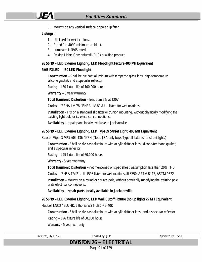
June 2019) 26 56 19 LED Exterior Lighting, LED Floodlight Fixture 400 MH Equivalent 26 56 19 LED Exterior Lighting, LED Type IV Street Light, 400 MH Equivalent
Facilities Standards
Revised: July 7, 2021 Revised By: JER Approved By: SSST
TABLE OF CONTENTS Page 8 of 129
26 56 19 LED Exterior Lighting, LED Wall Cutoff Fixture (no up light) 75 MH Equivalent 26 56 19 LED Exterior Lighting, LED Wall Pack Fixture 400 MH Equivalent 26 56 19 LED Light Fixture, Wall Pack, Exterior Location, Non Corrosive Environment (Revised
June 2019) 26 56 19 LED Light Fixture, Wet Location, Ambient Conditions (Revised July 2021) 26 61 23 LED Lamp Upgrade for HID Fixtures (Est. May 2021)
DIVISION 27 – COMMUNICATIONS
DIVISION 28 – ELECTRONIC SAFETY AND SECURITY
DIVISION 31 – EARTHWORK
DIVISION 32 – EXTERIOR IMPROVEMENTS 32 01 00 Operation & Maintenance of Exterior Improvements (Asphalt Pavement, Revised May
2021) 32 16 00 Curbs, Gutters, Sidewalks & Driveways (Concrete, Revised May 2021) 32 90 00 Lift Station Landscaping
Revised: January 26, 2017 Revised By: MDP Approved By: SSST
DIVISION 0-PROCUREMENT AND CONTRACTING REQUIREMENTS Page 9 of 129
DIVISION 0 – PROCUREMENT AND CONTRACTING REQUIREMENTS
Place Holder – Intentionally Left Blank
Facilities Standards
Revised: January 26, 2017 Revised By: MDP Approved By: SSST
DIVISION 1 –GENERAL REQUIREMENTS Page 10 of 129
DIVISION 1 – GENERAL REQUIREMENTS
Place Holder – Intentionally Left Blank
Facilities Standards
Revised: January 26, 2017 Revised By: MDP Approved By: SSST
DIVISION 2 –EXISTING CONDITIONS Page 11 of 129
DIVISION 2 – EXISTING CONDITIONS
Place Holder – Intentionally Left Blank
Facilities Standards
Revised: January 26, 2017 Revised By: MDP Approved By: SSST
DIVISION 3 –CONCRETE Page 12 of 129
DIVISION 3 – CONCRETE
Place Holder – Intentionally Left Blank
Facilities Standards
Revised: January 26, 2017 Revised By: MDP Approved By: SSST
DIVISION 4 –MASONRY Page 13 of 129
DIVISION 4 – MASONRY
Place Holder – Intentionally Left Blank
Facilities Standards
Revised: January 26, 2017 Revised By: MDP Approved By: SSST
DIVISION 5 –METALS Page 14 of 129
DIVISION 5 – METALS
Place Holder – Intentionally Left Blank
Facilities Standards
Revised: January 26, 2017 Revised By: MDP Approved By: SSST
DIVISION 6 –WOODS, PLASTICS, AND COMPOSITES Page 15 of 129
DIVISION 6 – WOOD, PLASTICS, AND COMPOSITES
Place Holder – Intentionally Left Blank
Facilities Standards
Revised: January 26, 2017 Revised By: MDP Approved By: SSST
DIVISION 7 –THERMAL AND MOISTURE PROTECTION Page 16 of 129
DIVISION 7 – THERMAL AND MOISTURE PROTECTION
07 52 16 – SBS Modified Bituminous Membrane Roofing The standard low slope roof system shall be a mineral surfaced SBS modified bitumen roof assembly with materials manufactured by:
Johns Manville, Siplast, or Soprema.
Facilities Standards
Revised: May 1, 2021 Revised By: JER Approved By: SSST
DIVISION 8 – OPENINGS Page 17 of 129
DIVISION 8 – OPENINGS
08 16 13 – Fiberglass Doors with Aluminum Frame (Revised June 2020) Special Lite Fiberglass Reinforced Polyester Door System (FRP) with Aluminum Frame or JEA approved equal
Features: • FRP skin - 0.12” thick • Class “C” exterior skin • Uses Corbin Russwin ML2000 mortise lockset – JEA standard • Hinges – 4.5” butt, continuous and offset pivots • 6063-T6 aluminum alloy door perimeter extrusions • Frame – 6063 -T6 hardened aluminum alloy • Options – fire rated and hurricane resistant • Core – water blown polyurethane foam
08 71 00 – Door Hinges ANSI A 156.1 Compliant full mortise type hinges ANSI A5111 (Stainless steel) For use on heavy weight doors and doors requiring high
frequency service. ANSI A5112 (Stainless steel) For use on medium weight doors and doors requiring medium
frequency service. ANSI A5133 (Stainless steel) For use on medium weight doors or door requiring low frequency
Mortise: Corbin Russwin, ML2000 Series-Heavy duty for medium to light used door Cylindrical: Corbin Russwin, CL3300 Series-Extra heavy duty for highly used door or
Corbin Russwin, CL3500 Series-Heavy duty for medium to lightly used door HANDLE AND TRIM:
Mortise: Lustra Lever Design Handle (LWA) for mortise lockset Satin Stainless Steel US32D (BHMA 630) finish
Cylindrical: Newport lever handle (NZD) Satin chrome plated (626) finish
Facilities Standards
Revised: May 1, 2021 Revised By: JER Approved By: SSST
DIVISION 8 – OPENINGS Page 18 of 129
CORE: Satin plated chromium (626), Complete Large Format Interchangeable Core (LFIC), 6-Pin high security, keyed to existing Corbin Russwin 60-70 series restricted system with construction control key.
KEY: Patented Corbin Russwin Master Keying System
NON-KEYED LOCKSET: Unless otherwise specified by the designer or architect and approved by the standard committee, any brand may be used that matches the Corbin Russwin style. All remodeled buildings and buildings slated for demolition shall have all locksets, cylinders, and keys returned to Facilities.
08 71 20 - -Door Hardware – Restroom Occupancy Lockset (Est June 2020) PRIVACY LOCK FOR SINGLE OCCUPANCY INTERIOR RESTROOM: This lock will be used in lieu of standard upper deadbolt same opening. Approved vendors are Yale or Schlage. Approved Models are:
Yale: D292 x 626, Master model Chrome D- series occupancy lock Schlage Corp.: B571 626 B580, Occupancy INDX Thumb Turn 626, Satin Chrome Schlage Corp.: D271 626 D200, Occupancy Grade 2 Non Handed Med. Duty Satin Chrome
Handle and Trim: Interior restroom doors are either push or pull to open, simple Satin Chrome Handle, and Push Plate Set on doors.
EXTERNAL RESTROOM USE – See Security Standards for Medeco Lock Sets.
08 71 53 – Electrified Locksets LOCKSET:
Mortise: Corbin Russwin, ML20606 NAC Series Electrified Mortise Lock with High Security Monitoring, Full model No. ML20606 PSM NAC SEC RO4 630 CL6
Cylindrical: Corbin Russwin, CL33905 Electrified Lockset – Fail Secure, Full Model No. CL33905 PZD 626 M92 SEC CL6
Corbin Russwin, CL33903 Electrified Lockset – Fail Safe, Full RIM Exit Device with Electric Trim:
Corbin Russwin, ED5200S Panic- Listed SecureBolt Exit Device, Full Model No. ED5200S PR9905 M92 630 CL6 M54
RIM Exit Device with Electric Latch Retraction: Corbin Russwin, ED5200S Panic-Listed SecureBolt Exit Device, Full Model
No. ED5200S P955 M95 M94 630 CL6 M54
Facilities Standards
Revised: May 1, 2021 Revised By: JER Approved By: SSST
Material – Wet-formed mineral fiber Surface Finish – Factory-applied latex paint Color – White Light Reflectance – White – 0.82 (rating per ASTM E1477) Weight – .69 lbs/SF depending on size of tile Size - 24”x 24”x 5/8” NRC – 0.55 CAC – minimum 33 Fire Performance - ASTM E84 and CAN/ULC S102 surface burning characteristics. Flame
Spread Index or less. Smoke Developed Index 50 or less (UL labeled) Anti-Mold/Mildew Bacteria – Standard Insulation Value - Average R factor is 1.5 BTU units 0.26 (Watt units) Sag Resistance – Standard VOC Emissions – Meets CA Dept. of Health Services Standard Practice for the testing of VOC
Emissions and is listed on CHPS High Performance Products Database for Low-Emitting Materials.
ASTM E1264 Classification – Type III, Form 2, Pattern c D; Fire Class A
Material – Ceramic and mineral fiber composite Surface Finish – Scrubbable factory-applied plastic finish Color – White Light Reflectance – White – 0.82 (rating per ASTM E1477) Weight – 1.40 lbs/SF depending on size of tile Size - 24”x 24”x 5/8” NRC – 0.55 CAC – minimum 40 Surface Burning Characteristics – Class A (Flame Spread 25 or under) UL Labeled Fire Resistance Rating – Fire Guard: A fire resistive ceiling when used in applicable UL
assemblies Anti-Mold & Mildew – Totally inorganic product Insulation Value - Average R factor is 1.4 (BTU units) 0.25 (Watt units) Sag Resistance – HumiGuard Max – maximum humidity resistance, including outdoor
applications ASTM E1264 Classification – Type XX (high density ceramic-like composition with scrubbable
finish), Pattern C E
Facilities Standards
Revised: January 26, 2017 Revised By: MDP Approved By: SSST
DIVISION 9 – FINISHES Page 21 of 129
09 90 00 – Painting & Coating (Sherwin Williams)
Sherwin Williams brand paint; finish and color to be determined by site conditions/requirements
09 96 56 – Water Based Epoxy Paint
Sherwin Williams Pro Industrial Water Based Catalyzed Epoxy, finish and color to be determined by site conditions/requirements. Application to be in high use/abuse locations: substation restrooms, lab facilities (if not covered under other standards/specifications), walls subject to impact (cart and chair storage areas, for example), and other areas as determined on a case-by-case basis.
Revised: May 1, 2021 Revised By: JER Approved By: SSST
DIVISION 10 – SPECIALTIES Page 22 of 129
DIVISION 10 – SPECIALTIES
10 16 16 – Dry Erase Board for Conference Room (Est June 2020)
The Quartet Infinity marker board – Glass, 4’ x 8’
10 11 23 – Restroom Janitorial Log Sheet Holder (Substation restrooms) Est. July 10, 2019 Clear acrylic wall mount sign holder, Vertical, for single sided 8.5” x 11” sheets. An example is the Deflecto Classic Image Wall Mount Sign Holder (68201).
Mounting: The holders will be attached using 2 drywall screws at the top of the holder for drywall walls, or 2 tapcons at the top of the holder for block walls. The holder will be mounted @52" AFF 6" from door light switch or most convenient accessible location if space at door light switch is not available.
10 14 16 – Bathroom Signage (Est. March 6, 2019) Provide visual, tactile and Grade 3 Braille information to assist all employees and visitors.
1. Design to meet Federal ADA / ADAAG Guideline for content, symbol design, text style, Braille translation and color contrast
2. Braille dots must meet ADA requirements for size, shape and spacing 3. All signs will have blue background with white lettering and symbols 4. Matte finish required to reduce glare and reflections for better visibility 5. Signs will be 9" h x 6" w, made of 1/16 blue acrylic substrate with 1/32 white tactile layer 6. If Family, signs require they will be 9" h x 9" w
Mounting signage 1. All signs will mounted on wall with double back tape 2. Signs shall be mounted per Section 703.4.1 and ANSI A117.1 703.3.10
a. Tactile characters on signs shall be located 48 inches minimum above the finished floor or ground surface, measured from the baseline of the lowest tactile character and 60 inches maximum above the finished floor or ground surface, measured from the baseline of the highest tactile character.
b. Signs should be mounted to the wall on the latch side or the door.
10 21 00 – Cubicle Systems Manufacturer: HON System: Abound
The panel is a frame and tile style that is stackable. Tiles will be fabric covered for most locations with the ability to have laminate or metal depending on placement. Fabric panel will be acoustical grade. Work surface will be high density laminate. Panel width will be 36” wide, 50” tall and 2-5/8” thick. Power supply will have the capability to be at work surface level.
Revised: May 1, 2021 Revised By: JER Approved By: SSST
DIVISION 10 – SPECIALTIES Page 23 of 129
Scranton – Solid Plastic; High Density Polyethylene (HDPE) Global – Color thru phenolic
Compartment style: Floor mounted, overhead braced Warranty: 15 Years Construction:
1. Doors, panels, and pilasters shall be 1 inch thick with all edges rounded to a 1/4 inch radius.
2. Doors and dividing panels shall be 55 inch high and mounted at 14 inch above the finished floor.
3. Pilasters shall be 82 inch high (standard) and fastened into a 3 inch high pilaster shoe with a stainless steel tamper resistant torx head sex bolt.
4. Door dimensions to meet ADA. 5. Color: To be selected from Manufacturer’s full line of textures and colors 6. Door Hardware
a. Hinges shall be 8 inch and fabricated from heavy-duty extruded aluminum (6463-T5 alloy) with bright dip anodized finish with wrap-around flanges, through bolted to doors and pilasters with stainless steel, torx head sex bolts. Hinges operate with field adjustable nylon cams. Cams can be field set in 30-degree increments OR, hinges shall be integral, fabricated from the door and pilaster with no exposed metal parts.
b. Door strike/keeper shall be 6 inch long and made of heavy-duty extruded aluminum (6436-T5 alloy) with a bright dip anodized finish and secured to the pilasters with stainless steel tamper resistant torx head sex bolts. Bumper shall be made of extruded black vinyl.
c. Latch and housing shall be made of heavy-duty extruded aluminum (6463-T5 alloy). The latch housing shall have a bright dip anodized finish, and the slide bolt and button shall have a black anodized finish.
d. Each door shall be supplied with one coat hook/bumper and door pull made of chrome plated zamak. Handicapped doors shall be supplied with a second door pull and out swing doors with one door stop made of chrome plated zamak.
7. Pilaster shoes shall be 3 inch high (type 304, 20 gauge) stainless steel. Pilaster shoes shall be secured to the pilaster with a stainless steel tamper resistant torx head hex bolt.
8. Wall brackets shall be 1 1/2 inch stirrup type made of heavy-duty aluminum (6463-T5 alloy) with a bright dip anodized finish. Stirrup brackets shall be fastened to pilasters and panels with stainless steel tamper resistant torx head hex bolts.
9. Head rail shall be made of heavy-duty extruded aluminum (6463-T5 alloy) with anti-grip design and integrated curtain track. The head rail shall have a clear anodized finish and shall be fastened to the head rail bracket by a stainless steel tamper resistant torx head hex bolt, and fastened at the top of the pilaster with stainless steel tamper resistant torx head screws.
10. Head rail brackets shall be 20 gauge stainless steel with a satin finish and secured to the wall with a stainless steel tamper resistant torx head screws.
Facilities Standards
Revised: May 1, 2021 Revised By: JER Approved By: SSST
DIVISION 10 – SPECIALTIES Page 24 of 129
10 28 13 – Electric Hand Dryer Excel Dryer Inc. Model Xlerator XL-W
Hand Dryer: High Speed, energy efficient, electric hand dryer; surface mounted; entire dryer internally grounded. Warranty Period: 5 years; limited warranty Manufacturing - MADE IN USA Certified, verify certification number Sound Level – Operational sound level less than 80 dB Provide 1.1” noise reduction nozzle Motor and Blower: 5/8 HP, 20,000 RPM. Air flow rate: 19,000 linear feet per minute Heater: 970 watts mounted inside blower housing to be vandal proof with Air Temperature of 135 degrees F measured at average hand position of 4 inches below air outlet Performance Criteria: Certified and labeled by Underwriters Laboratory, Inc. Power Source: 110/120 volt, 12.5 amp, 50 Hz or 60 Hz, 1500 Watts Controls: Completely sealed control board and optics, automatic operation, activated by infrared optical sensor Size: 11-3/4" wide by 12-11/16" high by 6-11/16" deep Green: GreenSpec Listed, Qualifies for LEED Credits Finish: White painted Optional – Stainless steel brushed Model XL-SB finishes for high abuse environments Mounting Height: Distance from floor to bottom of dryer. Men’s 45 inches (1,143 mm); Ladies’ 43 inches (1,092 mm) ; Handicapped 37 inches (940 mm)
10 28 13 – Hand Towel Dispenser Tork Elevation Matic Model 5510282
SKU: 5155-06 Fully ADA compliant - one-handed push operation Sight window makes it easy to check refill level Provide a black color unit unless Facilities approves otherwise Compatible with GOJO® FMX-12 1250 mL refills, installer to supply one refill unit in dispenser. Installation Locations: Place manual units only at unmanned facilities - i.e. Substations and Lift Stations.
Automatic Unit GOJO TFX Dispenser SKU: 2730-12 Touch-free foam soap dispenser Fully ADA compliant, UL/CE registered Sight window makes it easy to check refill level Provide a black color unit unless Facilities approves otherwise Compatible with GOJO® TFX™ 1200 mL refills, installer to supply one refill unit in dispenser. Uses “C” batteries for power – installer supplied with unit
Facilities Standards
Revised: May 1, 2021 Revised By: JER Approved By: SSST
DIVISION 10 – SPECIALTIES Page 25 of 129
Installation Locations: Place automatic units at all facilities except Substations and Lift Stations.
Construction: Casing: Durable ABS Plastic with rugged polycarbonate view windows (both recycling code number 7) Wall mounted only: Mounts to wall with included adhesive tape or optional hardware. Multiple hole pattern allows use of existing wall holes. Mounting Clearance: 10" (25.4 cm) clearance from bottom of dispenser to surface
10 28 13 – Toilet Paper Dispenser Tork Twin Jumbo Bath Tissue Roll Dispenser, Article 247549A, Color: Black, SCC: 10073286622393
10 28 13 – Toilet Seat Cover Dispenser Tork Toilet Seat Cover Dispenser, Article 344080, Color: White, SCC: 7310791218403 This item will be deployed only in limited locations and by approval of Facilities Manager.
10 28 16 – Bathroom Mirror (Est. March 2019) Non ADA Compliance Facilities requiring a mirror without shelf, manufacturers shall be:
Bradex Standard Model Series 780 Brey - Krause Model Series T-10XX-XX-SS or Bobrick B-165 series
Non ADA Compliance Facilities requiring a mirror with shelf, manufacturers shall be: Bradley - Bradex Standard Model Series 7805 Brey - Krause Model Series T-10XX-XX-SS with shelf option Bobrick B-166 series
ADA Compliance Facilities, manufacturers shall be: Bradex Standard Model Series 740 Bobrick B-293 series.
Equipment Description: Mirror with angled frame, welded corners. Frame made of one piece formed stainless steel ¾” x ¾” corners welded with satin finish Back of mirror is galvanized steel secured to frame with concealed screws Mirror is ¼” float glass, thermosetting infrared cured paint backing with poly glaze finish manufactured to ASTM C 1036 and ASTM C 1503 standards. Mirror is protected by ¼”extruded polystyrene between mirror and galvanized steel. Wall hanger is 18 gauge rolled steel all welded construction.
Facilities Standards
Revised: May 1, 2021 Revised By: JER Approved By: SSST
DIVISION 11 – EQUIPMENT Page 26 of 129
DIVISION 11 – EQUIPMENT
11 11 36 – DCFC LVLII 7 KW EV Charger (Est July 2020) The model shall be an ABB Terra DC Wallbox A. DC charger shall be suitable for outdoor or indoor installation with air temperature between -
40°C and+45°C (ambient temperature), without temperature de-rating B. Electrical:
1. 1 phase: 200 - 240 VAC, 100Amps. a. 1 phase 19.5 kW @208 V and V 22.5 kW @240 V
2. 3 phase: 200 - 240 VAC, 40Amps a. 3 phase: 0 to 22.5 kW nominal 24 kW at peak
3. Power factor: >96% at nominal output power 4. DC output voltage range
a. CCS 150 - 920 VDC b. CHAdeMO: 150 - 500 VDC
5. Max. DC output current a. 60 A
C. Interface & Communications: 1. DC charger shall support open protocol OPCC 1.6 for communication between
Electric Vehicle, EV Charger, and charging central management system to balance load demand and reduce infrastructure costs.
11 11 36 – Level II, 7W, Alternating Current, Charger for Electric Vehicles (Est July 2020) The model shall be a Novacharge 7000 or a PowerCharge E20SW which are identical units. Both are manufactured by Lite-On. EV charger shall be suitable for outdoor or indoor installation with air temperature between - 40°C and+45°C (ambient temperature), without temperature de-rating Electrical:
1 phase: 200 - 240 VAC, 32Amps. 1 phase 6.6 kW @208 V and 7.4 kW @240 V Power factor: >96% at nominal output power
Interface & Communications: EV charger shall support open protocol OCPP 1.6 for communication between Electric Vehicle, EV Charger and charging central management system to balance load demand and reduce infrastructure costs.
11 46 83 – Bin Style High Volume Use Ice Machine
Approved Manufactures for ice machines used at JEA for high volume use are the bin style manufactured by:
Hoshizaki or Manitowoc
Facilities Standards
Revised: May 1, 2021 Revised By: JER Approved By: SSST
DIVISION 11 – EQUIPMENT Page 27 of 129
The equipment must have an external water filtering system recommended by the manufacturer. If, additional capacity of ice is required, multiple ice machines must be installed. Stackable ice bins are not acceptable.
11 46 83 – Dispenser Style Ice Machine Approved Manufacturers for ice machine for office environment are the dispenser style (lever arm or touch-free) with nugget or cubelet size ice (no bigger than ¾” cube) suited for cup, glass, pitcher, and water dispenser manufactured by: Hoshizaki or Manitowoc The equipment will have an external water filtering system recommended by the manufacturer.
Revised: May 1, 2021 Revised By: JER Approved By: SSST
DIVISION 12 – FURNISHINGS Page 28 of 129
DIVISION 12 – FURNISHINGS
12 41 00 – Retrofit Sit Stand Work Station Device (Est June 2020) The Workrite Ergonomics - Solace Electric standing desk convertor will be utilized to retro fit work stations for FSR based height adjustable / sit stand request.
12 52 13 –Task-Chair for Accommodation Request (Est July 2020) The Humanscale Freedom Chair, with head rest, is to be utilized for requesters that have summited an accommodation request for a task chair with increased lumbar support.
12 52 13 –Task Chair for Harsh Environment Use (Est July 2020) The AllSeating Chiroform- Ultra 24/7- Highback Task chair will be utilized as the JEA standard harsh environment Task chair for use in plant and service center environments. Specifications:
MODEL CODE: 97111-T2-SE-BU-BN-KD-AS-F2-SIMPE CONTROLS: DELUXE TILTER HEAVY DUTY ARMS: TASK 2 ARM OPTIONS: SEAT SLIDER EXTENDED 3" RANGE BUMPER TRIM BALLISTIC NYLON BACK CASTERS: HEAVY DUTY CARPET STANDARD FABRIC: TRIUMPH; J ENNIS - IMPERIAL BLUE
12 52 13 – Task Chair for Standard Use (Est July 2020) The AllSeating YOU HighBack Task chair will be utilized as the JEA standard Task chair for up to 8 hours of use in an office environment. Dimensions
* Overall [Deluxe Synchro Tilt]: 45" - 48.5" H | 28" W | 28" D * Seat [Deluxe Synchro Tilt]: 17" - 20.5" H | 20.25" W | 18.5" D * Back: 27" H | 17.5" W
Fabric * Open Mesh: Ebony, Cobalt, Silica, Sandstone, Herbal Green, Dark Grey, & Black Honeycomb * Closed Mesh: Black & White * 200+ textiles to choose from * COM – 0.75 yards
Facilities Standards
Revised: May 1, 2021 Revised By: JER Approved By: SSST
DIVISION 12 – FURNISHINGS Page 29 of 129
Warranty: 12 year comprehensive parts and labor, with weight limit of 350 lbs.
12 52 13 – Task Chair for Weight Specific Standard Use (Est July 2020) The AllSeating Chiroform Big Task chair will be utilized as the JEA standard Task chair for up to 8 hours of use in an office environment. The highly durable Chiroform chair reinforced to support individuals weighing up to 500 pounds Features Memory foam seat, 6 ply Canadian maple seat pan, double curve backrest, t-nut construction, suitable for up to 500 lbs. • Dimensions
Overall [Deluxe Tilter Heavy Duty]: 41" - 46.5" H | 27" W | 27" D Seat [Deluxe Tilter Heavy Duty]: 17.75" - 23.25" H | 23.5" W | 21" D Back: 22" H | 22.25" W
• Fabric 200+ textiles to choose from COM – 2.75 yards
Warranty: 12 year comprehensive parts and labor, with weight limit of 500 lbs. click here to view details.
Facilities Standards
Revised: January 26, 2017 Revised By: MDP Approved By: SSST
DIVISION 13 – SPECIAL CONSTRUCTION Page 30 of 129
DIVISION 13 – SPECIAL CONSTRUCTION
Place Holder – Intentionally Left Blank
Facilities Standards
Revised: January 26, 2017 Revised By: MDP Approved By: SSST
DIVISION 14 – CONVEYING EQUIPMENT Page 31 of 129
DIVISION 14 – CONVEYING EQUIPMENT
Place Holder – Intentionally Left Blank
Facilities Standards
Revised: January 26, 2017 Revised By: MDP Approved By: SSST
DIVISION 21 – FIRE SUPPRESSION Page 32 of 129
DIVISION 21 – FIRE SUPPRESSION
Place Holder – Intentionally Left Blank
Facilities Standards
Revised: May 1, 2021 Revised By: JER Approved By: SSST
DIVISION 22 – PLUMBING Page 33 of 129
DIVISION 22 – PLUMBING
22 05 53 – Abbreviations for Identification on Plumbing Piping Equipment (Est. Sep 2020 Plumbing Abbreviations for piping, equipment, and system labels or tags Cross reference to JEA Standard 22 05 53 Plumbing, Piping, Equipment, and Systems Identification and ASME/ANSI Standard Y14.38 -2019 AFF – Above finished floor AW - Acid waste AV – Acid vent BOP – Bottom of pipe BF-VLV – Butterfly valve BL-VLV – Ball valve CA – Compressed air CB - Catch Basin CD - Condensate drain CFH – Cubic foot per hour CI - Cast iron CO – Cleanout CV or C-VLV – Control valve CW – Cold Water DI - Deionized water DN - Down DS – Downspout FCO - Floor Cleanout FD – Floor drain FO – Fuel oil FOF – Fuel Oil fill FOG – Fuel Oil Gauge FOR – Fuel Oil Gauge FOS – Fuel Oil supply FOV – Fuel Oil vent FS – Floor Sink G – Gas GA – Gage or gauge GB-VLV – Globe valve GPH – Gallons per Hour GPM – Gallons per Minute GR – Grease GT-VLV – Gate Valve HB – Hose Bibb HD – Hub Drain HW – Hot Water HWR – Hot Water Recirculating
ID – Internal Diameter or Inside Dimension IE – Invert Elevation IW – Indirect Waste KW – Kilowatt KWH – Kilowatt hour LBS – Pounds LWT – Leaving Water Temperature MA or A – Medical Air MH – Manhole MV or V – Medical Vacuum NC – Normally Closed NI or N – Nitrogen N2O – Nitrous Oxide NO – Normally Open NP – Non Potable Water OD – Outside Diameter or Outside Dimension OX or O – Oxygen PRV – Pressure Reducing Valve PRS – Pressure Reducing Station PSI – Pounds per Square Inch PVC – Polyvinyl Chloride RD – Roof Drain RPBP – Reduced Pressure Backflow Preventer SD – Storm Drain SF – Square Foot SS or SSTL – Stainless Steel ST – Storm STL – Steel STO – Overflow Storm Drain V – Vent VAC – Vacuum VTR – Vent thru Roof WCO – Wall Cleanout WTR - Water
Facilities Standards
Revised: May 1, 2021 Revised By: JER Approved By: SSST
DIVISION 22 – PLUMBING Page 34 of 129
22 05 53 – Identification for Plumbing & Equipment (Pipe Labels) (Revised September 2020)
Installation of labels as detailed below, on all newly installed water lines. Labels are to denote temperature, direction, and type of water (chilled water, potable, irrigation, etc.). Requirements for labelling are to be included in all plumbing specifications for both new construction and upgrades.
EQUIPMENT LABELS A. Metal Labels for Equipment:
1. Material and Thickness: Brass, 0.032-inch, Stainless steel, 0.025-inch or anodized aluminum, 0.032-inch minimum thickness, and having predrilled or stamped holes for attachment hardware.
2. Minimum Label Size: Length and width vary for required label content, but not less than 2-1/2 by 3/4 inch.
3. Minimum Letter Size: 1/4 inch for name of units if viewing distance is less than 24 inches, 1/2 inch for viewing distances up to 72 inches, and proportionately larger lettering for greater viewing distances. Include secondary lettering two-thirds to three fourths the size of principal lettering.
4. Fasteners: Stainless-steel rivets or self-tapping screws. 5. Adhesive: Contact-type permanent adhesive, compatible with label and with substrate.
B. Plastic Labels for Equipment:
1. Material and Thickness: Multilayer, multicolor, plastic labels for mechanical engraving, 1/8 inch thick, and having predrilled holes for attachment hardware.
2. Letter Color: White 3. Background Color: Black 4. Maximum Temperature: Able to withstand temperatures up to 160 deg F. 5. Minimum Label Size: Length and width vary for required label content, but not less than 2-
1/2 by 3/4 inch. 6. Minimum Letter Size: 1/4 inch for name of units if viewing distance is less than 24 inches,
1/2 inch for viewing distances up to 72 inches, and proportionately larger lettering for greater viewing distances. Include secondary lettering two-thirds to three-fourths the size of principal lettering.
7. Fasteners: Stainless-steel rivets or self-tapping screws. 8. Adhesive: Contact-type permanent adhesive, compatible with label and with substrate.
C. Label Content: Include equipment's Drawing designation or unique equipment number, Drawing numbers where equipment is indicated (plans, details, and schedules), plus the Specification Section number and title where equipment is specified.
D. Equipment Label Schedule: For each item of equipment to be labeled, on 8-1/2-by-11 inch bond paper. Tabulate equipment identification number and identify Drawing numbers where equipment is indicated (plans, details, and schedules), plus the Specification Section number
Facilities Standards
Revised: May 1, 2021 Revised By: JER Approved By: SSST
DIVISION 22 – PLUMBING Page 35 of 129
and title where equipment is specified. Equipment schedule shall be included in operation and maintenance data.
WARNING SIGNS AND LABELS A. Material and Thickness: Multilayer, multicolor, plastic labels for mechanical engraving, 1/8
inch thick, and having predrilled holes for attachment hardware.
B. Letter Color: White
C. Background Color: Red
D. Maximum Temperature: Able to withstand temperatures up to 160 deg F.
E. Minimum Label Size: Length and width vary for required label content, but not less than 2-1/2 by 3/4 inch.
F. Minimum Letter Size: 1/4 inch for name of units if viewing distance is less than 24 inches, 1/2 inch for viewing distances up to 72 inches, and proportionately larger lettering for greater viewing distances. Include secondary lettering two-thirds to three-fourths the size of principal lettering.
G. Fasteners: Stainless-steel rivets or self-tapping screws.
H. Adhesive: Contact-type permanent adhesive, compatible with label and with substrate.
I. Label Content: Include caution and warning information, plus emergency notification instructions.
PIPE LABELS A. General Requirements for Manufactured Pipe Labels: Preprinted, color-coded, with lettering
indicating service, and showing flow direction.
B. Pre-tensioned Pipe Labels: Pre-coiled, semi-rigid plastic formed to cover full circumference of pipe and to attach to pipe without fasteners or adhesive.
C. Self-Adhesive Pipe Labels: Printed plastic with contact-type, permanent-adhesive backing.
D. Pipe Label Contents: Include identification of piping service using same designations or abbreviations as used on Drawings, pipe size, and an arrow indicating flow direction.
1. Flow-Direction Arrows: Integral with piping system service lettering to accommodate both directions, or as separate unit on each pipe label to indicate flow direction.
2. Lettering Size: At least 1-1/2 inches high.
STENCILS A. Stencils: Prepared with letter sizes according to ASME A13.1 for piping; minimum letter height
of 1-1/4 inches for ducts; and minimum letter height of 3/4 inch for access panel and door labels, equipment labels, and similar operational instructions.
1. Stencil Material: Aluminum, Brass, Fiberboard or metal.
Facilities Standards
Revised: May 1, 2021 Revised By: JER Approved By: SSST
DIVISION 22 – PLUMBING Page 36 of 129
2. Stencil Paint: Exterior, gloss, alkyd enamel or acrylic enamel (as appropriate for the material being painted) , black unless otherwise indicated. Paint may be in pressurized spray-can form.
3. Identification Paint: Exterior, alkyd enamel or acrylic enamel in colors according to ASME A13.1 unless otherwise indicated.
VALVE TAGS A. Valve Tags: Stamped or engraved with 1/4-inch letters for piping system abbreviation and
1/2inch numbers. 1. Tag Material: Brass, 0.032-inch, Stainless steel, 0.025-inch or anodized aluminum, 0.032-
inch minimum thickness, and having predrilled or stamped holes for attachment hardware. 2. Fasteners: Brass wire-link or beaded chain; or S-hook.
B. Valve Schedules: For each piping system, on 8-1/2-by-11-inch bond paper. Tabulate valve number, piping system, system abbreviation (as shown on valve tag), location of valve (room or space), normal-operating position (open, closed, or modulating), and variations for identification. Mark valves for emergency shutoff and similar special uses. 1. Valve-tag schedule shall be included in operation and maintenance data.
22 11 19 – Backflow Devices – Cross Connection Control Standard (Est June 2018) The backflow prevention device shall be the type as listed in JEA’s “Rules and Regulations for Water and Wastewater Services” manual. Operation and maintenance of this cross connection device shall comply with JEA’s cross connection control program and associated policies. All reduce pressure assemblies shall be mounted above grade. Minimum distance from the ground 12 inches measured from the ground to mid-way point of the BFP body for all units 3 inches and smaller. All other backflows min height 12 inches from ground to bottom of Backflow body. Refer to Water / Waste Standards for maximum installation height allowed by JEA. JEA approved device manufacturers are Wilkens, Apollo and Watts. Back flow devices shall have freeze valves and stainless steel valves handles. JEA approved Freeze Protection Device is Dole SP35 or Dole SP45. Refer to Water/Waste Water Standards for backflow installation requirements. Additional Requirements: All Backflow preventers shall have a Freeze Protection Valve installed by a Licensed Plumber or state certified Backflow assembly tester. For More Information:
JEA Cross Connection Control Policy Rules and Regulations for Water and Wastewater Services manual Florida Administrative Code Chapter 62-555
Revised: May 1, 2021 Revised By: JER Approved By: SSST
DIVISION 22 – PLUMBING Page 37 of 129
22 41 13 – Toilet Seat – Plastic Bemis 1655CT series Construction - Injection molded solid plastic seat Rating – Commercial Heavy Duty Color - White Performance – Fully rated for dead end service Codes – IAMPO/ANSI Z124.5 Availability – locally available in Jacksonville. Design – 300 series stainless steel hinge posts and pintles, open front without a cover, hold down bolts that do not loosen with normal use-
22 42 13 Commercial Urinals (Est June 2020) Basis of design: American Standard Allbrook FloWise Universal Urinal Other brands that meet this Basis of Design: Kohler K-5016-ET-0 Dexter Elongated Urinal ProFlo FP1805WH Features:
*Vitreous China *High efficiency operation range of 0.5 gpf - 1.0 gpf *Flushing rim *Siphon jet flush action *3/4" inlet spud *Outlet connection threaded 2" inside (NPTF) *Wall hanger *Meets ANSI flush requirements at 0.5 gpf and 1.0 gpf *Nominal dimensions: 14-15/16" x 14-15/16" x 21-1/2"
22 42 13 – Floor Mounted Back Outlet Toilet Bowl (Revised June 2020) Zurn 5645-bwl, Elongated toilet bowl American Standard Huron 3312.001, elongated toilet bowl
**All toilets are to be installed with the rim at ADA height, 17” – 19”.
Facilities Standards
Revised: May 1, 2021 Revised By: JER Approved By: SSST
DIVISION 22 – PLUMBING Page 38 of 129
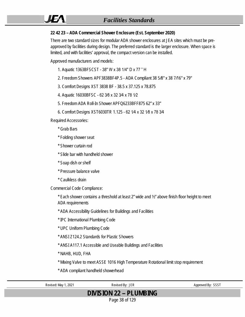
22 42 23 – ADA Commercial Shower Enclosure (Est. September 2020) There are two standard sizes for modular ADA shower enclosures at JEA sites which must be pre-approved by facilities during design. The preferred standard is the larger enclosure. When space is limited, and with facilities’ approval, the compact version can be installed.
Approved manufacturers and models:
1. Aquatic 1363BFSCST - 38″ W x 38 1/4″ D x 77 ” H
2. Freedom Showers APF3838BF4P.5 - ADA Compliant 38 5/8" x 38 7/16" x 79”
3. Comfort Designs XST 3838 BF - 38.5 x 37.125 x 78.875
4. Aquatic 16030BFSC - 62 3⁄8 x 32 3⁄4 x 78 1⁄2
5. Freedom ADA Roll-In Shower APFQ6233BFF875 62” x 33”
6. Comfort Designs XST6030TR 1.125 - 62 1⁄4 x 32 1⁄8 x 78 3⁄4
Required Accessories:
* Grab Bars
* Folding shower seat
* Shower curtain rod
* Slide bar with handheld shower
* Soap dish or shelf
* Pressure balance valve
* Caulkless drain
Commercial Code Compliance:
* Each shower contains a threshold at least 2” wide and ½” above finish floor height to meet ADA requirements
* ADA Accessibility Guidelines for Buildings and Facilities
* IPC International Plumbing Code
* UPC Uniform Plumbing Code
* ANSI Z124.2 Standards for Plastic Showers
* ANSI A117.1 Accessible and Useable Buildings and Facilities
* NAHB, HUD, FHA
* Mixing Valve to meet ASSE 1016 High Temperature Rotational limit stop requirement
* ADA compliant handheld showerhead
Facilities Standards
Revised: May 1, 2021 Revised By: JER Approved By: SSST
DIVISION 22 – PLUMBING Page 39 of 129
22 42 13 – Floor Mounted Floor Outlet Gravity Tank Toilet Bowl American Standard – Champion 4; Model 2002.014 Kohler – Cimarron; Model K-3589 Zurn – Z-HPT; Model Z5551-K These water closets are able to flush waste in buildings without enough water pressure (less than 30 psi) to properly operate a flushometer unit such as the Sloan Royal Valve.
22 42 13 – Floor Mounted Floor Outlet with Flush Valve Connection Elongated Water Closet American Standard - Madera; Model 3043 Kohler – Highline; Model K-4405 Zurn – Z-HET; Model Z5565-K These water closets are able to flush waste in buildings with sufficient water pressure (above 25 psi) to properly operate a flushometer unit such as the Sloan Royal Valve. Construction - Vitreous china, glazed trap way Height – Must meet ADA minimum rim dimension of 16.125” Flow Rating – 1.6 gallons per flush. Color - White Performance Score – 1,000 grams or more MaP Codes – ASME A112.19.2 for vitreous china, ADA/ICC/ANSI 117.1. Installation – Floor outlet centerline shall be 12” or less from the finished wall Availability – repair parts locally available in Jacksonville. Design – Smooth contours, easy to clean
22 42 39 – Lavatory Single Lever Faucet Chicago (420-ABCP) deck mounted 4”- single lever Hot and Cold water mixing faucet with 0.5 GPM non-aerating spray and ceramic cartridge.
Lead-free, brass ball, stem and body construction, chrome plated for corrosion protection
22 42 39 – Sloan Royal Flush Valve Sloan Royal Flush Valve
Facilities Standards
Revised: May 1, 2021 Revised By: JER Approved By: SSST
DIVISION 22 – PLUMBING Page 40 of 129
22 45 33 – Combination Emergency Fixture Unit Combination Safety Shower with Stainless Steel Round Eyewash and Stainless Steel Showerhead System: Speakman SE 693-SSH
Facilities Standards
Revised: May 1, 2021 Revised By: JER Approved By: SSST
DIVISION 23 – HEATING, VENTILATION, AND AIR CONDITIONING (HVAC) Page 41 of 129
DIVISION 23 – HEATING, VENTILATION, AND AIR CONDITIONING (HVAC)
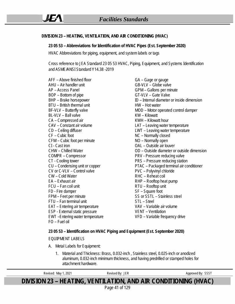
23 05 53 – Abbreviations for Identification of HVAC Pipes (Est. September 2020) HVAC Abbreviations for piping, equipment, and system labels or tags
Cross reference to JEA Standard 23 05 53 HVAC, Piping, Equipment, and Systems Identification and ASME/ANSI Standard Y14.38 -2019
AFF – Above finished floor AHU – Air handler unit AP – Access Panel BOP – Bottom of pipe BHP – Brake horsepower BTU – British thermal unit BF-VLV – Butterfly valve BL-VLV – Ball valve CA – Compressed air CAV – Constant air volume CD – Ceiling diffuser CF – Cubic foot CFM – Cubic foot per minute CI - Cast iron CHW – Chilled Water COMPR – Compressor CT - Cooling tower CU – Condensing unit or copper CV or C-VLV – Control valve CW – Cold Water EA – Exhaust air FCU – Fan coil unit FD - Fire damper FPM – Feet per minute FTU – Fan terminal unit EAT – Entering air temperature ESP - External static pressure EWT –Entering water temperature FO – Fuel oil
GA – Gage or gauge GB-VLV – Globe valve GPM – Gallons per minute GT-VLV – Gate Valve ID – Internal diameter or inside dimension HW – Hot water MOD – Motor operated control damper KW – Kilowatt KWH – Kilowatt hour LAT – Leaving water temperature LWT – Leaving water temperature NC – Normally closed NO – Normally open OAL – Outside air louver OD – Outside diameter or outside dimension PRV - Pressure reducing valve PRS – Pressure reducing station PTAC – Packaged terminal air conditioner PVC – Polyvinyl chloride RHC – Reheat coil RHP – Rooftop heat pump RTU – Rooftop unit SF – Square foot SS or SSTL – Stainless steel STL – Steel VAV – Variable air volume VENT – Ventilation VFD – Variable frequency drive
23 05 53 – Identification on HVAC Piping and Equipment (Est. September 2020) EQUIPMENT LABELS A. Metal Labels for Equipment:
1. Material and Thickness: Brass, 0.032-inch , Stainless steel, 0.025-inch or anodized aluminum, 0.032-inch minimum thickness, and having predrilled or stamped holes for attachment hardware.
Facilities Standards
Revised: May 1, 2021 Revised By: JER Approved By: SSST
DIVISION 23 – HEATING, VENTILATION, AND AIR CONDITIONING (HVAC) Page 42 of 129
2. Minimum Label Size: Length and width vary for required label content, but not less than 2-1/2 by 3/4 inch.
3. Minimum Letter Size: 1/4 inch for name of units if viewing distance is less than 24 inches, 1/2 inch for viewing distances up to 72 inches, and proportionately larger lettering for greater viewing distances. Include secondary lettering two-thirds to three fourths the size of principal lettering.
4. Fasteners: Stainless-steel rivets or self-tapping screws. 5. Adhesive: Contact-type permanent adhesive, compatible with label and with substrate.
B. Plastic Labels for Equipment: 1. Material and Thickness: Multilayer, multicolor, plastic labels for mechanical engraving, 1/8
inch thick, and having predrilled holes for attachment hardware. 2. Letter Color: White 3. Background Color: Black 4. Maximum Temperature: Able to withstand temperatures up to 160 deg F. 5. Minimum Label Size: Length and width vary for required label content, but not less than 2-
1/2 by 3/4 inch. 6. Minimum Letter Size: 1/4 inch for name of units if viewing distance is less than 24 inches,
1/2 inch for viewing distances up to 72 inches, and proportionately larger lettering for greater viewing distances. Include secondary lettering two-thirds to three-fourths the size of principal lettering.
7. Fasteners: Stainless-steel rivets or self-tapping screws. 8. Adhesive: Contact-type permanent adhesive, compatible with label and with substrate.
C. Label Content: Include equipment's Drawing designation or unique equipment number, Drawing numbers where equipment is indicated (plans, details, and schedules), plus the Specification Section number and title where equipment is specified.
D. Equipment Label Schedule: For each item of equipment to be labeled, on 8-1/2-by-11 inch bond paper. Tabulate equipment identification number and identify Drawing numbers where equipment is indicated (plans, details, and schedules), plus the Specification Section number and title where equipment is specified. Equipment schedule shall be included in operation and maintenance data.
WARNING SIGNS AND LABELS A. Material and Thickness: Multilayer, multicolor, plastic labels for mechanical engraving, 1/8 inch
thick, and having predrilled holes for attachment hardware. B. Letter Color: White C. Background Color: Red D. Maximum Temperature: Able to withstand temperatures up to 160 deg F. E. Minimum Label Size: Length and width vary for required label content, but not less than 2-1/2
by 3/4 inch.
Facilities Standards
Revised: May 1, 2021 Revised By: JER Approved By: SSST
DIVISION 23 – HEATING, VENTILATION, AND AIR CONDITIONING (HVAC) Page 43 of 129
F. Minimum Letter Size: 1/4 inch for name of units if viewing distance is less than 24 inches, 1/2 inch for viewing distances up to 72 inches, and proportionately larger lettering for greater viewing distances. Include secondary lettering two-thirds to three-fourths the size of principal lettering.
G. Fasteners: Stainless-steel rivets or self-tapping screws. H. Adhesive: Contact-type permanent adhesive, compatible with label and with substrate. I. Label Content: Include caution and warning information, plus emergency notification
instructions. PIPE LABELS A. General Requirements for Manufactured Pipe Labels: Preprinted, color-coded, with lettering
indicating service, and showing flow direction. B. Pre-tensioned Pipe Labels: Pre-coiled, semi-rigid plastic formed to cover full circumference of
pipe and to attach to pipe without fasteners or adhesive. C. Self-Adhesive Pipe Labels: Printed plastic with contact-type, permanent-adhesive backing. D. Pipe Label Contents: Include identification of piping service using same designations or
abbreviations as used on Drawings, pipe size, and an arrow indicating flow direction. 1. Flow-Direction Arrows: Integral with piping system service lettering to accommodate both directions, or as separate unit on each pipe label to indicate flow direction. 2. Lettering Size: At least 1-1/2 inches high. STENCILS A. Stencils: Prepared with letter sizes according to ASME A13.1 for piping; minimum letter height
of 1-1/4 inches for ducts; and minimum letter height of 3/4 inch for access panel and door labels, equipment labels, and similar operational instructions. 1. Stencil Material: Aluminum, Brass, Fiberboard or metal. 2. Stencil Paint: Exterior, gloss, alkyd enamel or acrylic enamel (as appropriate for the
material being painted) , black unless otherwise indicated. Paint may be in pressurized spray-can form.
3. Identification Paint: Exterior, alkyd enamel or acrylic enamel in colors according to ASME A13.1 unless otherwise indicated.
VALVE TAGS B. A. Valve Tags: Stamped or engraved with 1/4-inch letters for piping system abbreviation and
1/2inch numbers. 1. Tag Material: Brass, 0.032-inch, Stainless steel, 0.025-inch or anodized aluminum, 0.032-
inch minimum thickness, and having predrilled or stamped holes for attachment hardware. 2. Fasteners: Brass wire-link or beaded chain; or S-hook.
C. B. Valve Schedules: For each piping system, on 8-1/2-by-11-inch bond paper. Tabulate valve number, piping system, system abbreviation (as shown on valve tag), location of valve (room
Facilities Standards
Revised: May 1, 2021 Revised By: JER Approved By: SSST
DIVISION 23 – HEATING, VENTILATION, AND AIR CONDITIONING (HVAC) Page 44 of 129
or space), normal-operating position (open, closed, or modulating), and variations for identification. Mark valves for emergency shutoff and similar special uses. 1. Valve-tag schedule shall be included in operation and maintenance data.
23 05 50 – Corrosion Coating Specifications for HVAC Units (Est. March 2015, Rev. June 2019) Bronze Glow Coating
All coil(s) (condenser, evaporator, reheat, etc.) will have the refrigerant removed and stored for later installation. All copper tubing will be capped and coil charged with 200 lbs. of nitrogen to insure no leaks develop in the coating process. Coils are to be removed from the HVAC units and :
1. Cleaned with Bronz-Glow cleaners & hot treated water. 2. Spray primed with Bronz-Glow “ Husky Gold Primer “. 3. Dip coated (submerged in tank) with Bronz-Glow “Husky Gold Protectant”.
All copper tubing, compressors, and metal components in the unit will be cleaned, primed and protective coated with Bronz-Glow “Component Coat“ (Husky Gold can also be used for this function).
1. Components include: All metal devices attached to the copper tubing, such as filter dryers, receivers, reversing valves, compressors, solenoids, sensors, etc.
2. Condenser fan motor and blades – only when specifically approved by a JEA Facilities foreman.
3. Evaporator Blower assembly – only when specifically approved by a JEA Facilities foreman.
4. Interior Cabinetry – only when specifically approved by a JEA Facilities foreman. All brazed soldered joints (due to their combination of metals) are very susceptible to corrosion and deteriorate faster than the rest of the copper. These joints will get extra cleaning to remove any patina, primer and double the normal amount of protectant coat. Once treated, the coil(s) will be reinstalled into the unit, the unit will be evacuated, recharged with refrigerant, inspected, and readied for shipment.
23 05 66 UVC Fixture for HVAC (Est. August 2020) The selected products are as follows: A. Acceptable Manufacturers:
B. Quality Assurance: 4. Qualifications: UV-C products supplier shall provide proof of 100% inbound and outbound
testing of equipment.
Facilities Standards
Revised: May 1, 2021 Revised By: JER Approved By: SSST
DIVISION 23 – HEATING, VENTILATION, AND AIR CONDITIONING (HVAC) Page 45 of 129
5. Fixturing: The UV Power Supply shall have been tested, Listed and labeled as compliant with UL, CSA and CE.
6. Plenum Wiring Loom: The Loom shall meet UL Subject 13 and UL 1581, Article 725 of the NEC and meet UL VW-1 material ratings.
7. Lamps: Each lamp shall contain no more than 5 milligrams of mercury consistent with current environmental practices. Lamps shall include an inner layer comprising of at least one element from the series formed by magnesium, aluminum, titanium, zirconium, and rare earths to repel alkali metals (e.g. mercury) thereby extending lamp life. Lamps shall not produce ozone and shall have the option of being hermetically sealed within a layer of UV-C transmissible FTP to protect against lamp breakage and to contain lamp contents should breakage occur.
C. Warranty: 1. Power supply and fixturing shall be warranted to be free from defects for a period of five
(5) years. 2. Lamps shall be warranted to be free from defects for a period of two (1) year.
D. Design Requirements 1. Irradiation: Lamps shall be installed in sufficient quantity and in such a manner so as to
provide an equal distribution of UV-C energy. When installed, the UV-C energy produced shall be of the lowest possible reflected and shadowed-losses and shall produce 360 degree UV-C irradiance from the lamps within the UV cavity.
2. Intensity: Fixture modeling shall be included in the submittal and must contain the necessary calculations to demonstrate that a minimum of 7.5 lamp watts, as recommended by ASHRAE, are distributed equally to each square foot of coil surface area, and a minimum of 100 microwatts per square centimeter equally distributed to the surfaces at the plenum sides, top and bottom. All calculations are to be at 55 degrees F and 500 fpm air velocity, no exceptions.
3. Installation: The power supply housing shall be capable of installation within the air stream, secondary compartment or NEMA enclosure. Lamps shall be mounted to irradiate the intended surfaces as well as all of the available line of sight airstream through proper placement, 360° irradiation and incident angle reflection.
4. Safety: To protect personnel, all access panels and doors to the UV-C assembly and/or within view of the UV-C assembly shall include mechanical interlock switches to insure that the UV-C assembly will be de-energized when any of these accesses are opened. A redundant disconnect service switch is to be installed on the AHU’s exterior, in plain sight, to provide a method to more specifically de-energize the UV-C lamp circuits prior to entering the lamp plenum.
E. Equipment 1. Power Supply: Power supply shall be UL Listed, 120-277Vac - 50/60Hz, SO type. They
shall be High Power Factor, Low THD, Class P, Sound Rated “A”, Type 1 Outdoor designs with inherent Thermal Protection, no PCB’s and labeled for field wiring. They shall be capable of operating at temperatures of from 1-90 degrees C while producing the specified output and organism destruction at no more than 10 Watts of power consumption for each square foot of treated, cross sectional plane. The power supply shall be capable of ensuring a minimum of 9000 hours of lamp life, and with greater than 80% of its initial
Facilities Standards
Revised: May 1, 2021 Revised By: JER Approved By: SSST
DIVISION 23 – HEATING, VENTILATION, AND AIR CONDITIONING (HVAC) Page 46 of 129
output at end of lamp life. Power supply shall be protected against “end of lamp life” conditions, and warranted for 5 years.
2. Plenum Wiring: Shall be of sufficient length to facilitate lamp connection to a remotely mounted power supply. The lamp wiring shall be capable of being mounted anywhere in the system and/or as shown on the plans. The wiring shall meet UL Subject 13 and UL 1581, Article 725 of the NEC and meet UL VW-1 material ratings, as Plenum Rated. The wiring and wireway shall be constructed of ozone and UV-C resistant materials.
3. Lamp Plug & Holder: Shall be UL listed, 4 - pin type capable of accommodating a single-ended or a double-ended lamp. The holder shall be constructed of UV resistant materials and designed to connect the lamp to the plug, holder and plenum wiring to protect against electrical shock, moisture and separation.
4. Lamp Clamp: Each lamp plug and plenum rated wire connection shall have a UVC resistant, adjustable clamp to ensure a tight connection and seal between the lamp, lamp socket, lamp plug, and wiring to prevent electrical shock, connection shorts and/or lamp or ballast failure from lamp pin oxidation or arcing.
5. Lamps: Each lamp shall contain less than 5 milligrams of mercury, consistent with current environmental practices. Lamps shall include an inner layer comprising of at least one element from the series formed by magnesium, aluminum, titanium, zirconium, and rare earths to repel alkali metals (e.g. mercury) to extending lamp life. Lamp life shall be a minimum of 9,000 hours with no more than a 20% output loss at the end of the lamps life (12 months of continuous use). Lamps shall be constructed with UV-C resistant bases and shall not produce ozone. Lamps shall produce the specified output in moving air of up to 1000 fpm and temperatures of 0-90° C. Lamps shall have an option to be hermetically sealed within a layer of UV-C transmissible FEP to provide protection against lamp breakage and to ensure lamp contents from a broken Lamp, are contained.
23 09 13 – Thermostats The Honeywell T6 Pro series HP/Conventional, non-programmable and 7 day programmable digital thermostat to replace the discontinued Honeywell Models 5000, 6000, & 8000
23 09 23 – Building Automation System (BAS) STRUXUREWARE AUTOMATED LOGIC ALERTON
23 09 23 – Struxureware Building Operations System (SBO) (For JEA Plaza I, II & III) Struxureware Building Operations system (SBO)
23 21 23 Hydronic Air-Dirt Separator (Est August 2020) The selected products are as follows: A. Acceptable Manufacturers:
a. Elbi. b. Spirotherm.
Facilities Standards
Revised: May 1, 2021 Revised By: JER Approved By: SSST
DIVISION 23 – HEATING, VENTILATION, AND AIR CONDITIONING (HVAC) Page 47 of 129
c. Taco 4900, Inc.
B. Tank:
a. Air and dirt removal device shall be constructed of steel. It shall be designed, fabricated and stamped per ASME Section VIII Division 1 with a maximum working pressure of 125 psi at 270°F.
b. Manufacturer shall be holder of ASME U stamp.
c. Manufacturer to have optional 150 psi and 250 psi ASME units available.
C. Connections:
a. Units up to three 3-inch in size shall be provided with threaded connections as standard. Units four 4-inch and larger shall be provided with flanged system connections as standard. Inlet and outlet connections to be in line with piping system. Both inlet and outlet to be in the same horizontal and vertical planes.
D. Venting:
a. Each air and dirt removal device shall be equipped with a brass conical shaped air venting chamber designed to minimize system fluid from fouling the venting assembly. The air vent shall be able to be closed to allow flushing and purging of dirt via side port without dirt passing through vent on initial system fill.
E. Flushing:
a. A brass flushing cock shall be located on the side of each separator to facilitate system fast-fill and removal of the floating impurities from the air system interface within the separator.
F. Blow Down
a. A blow down valve shall be provided by the unit manufacturer on the bottom of each unit to allow blow down and cleaning. On units 2 ½” and smaller the valve and all of its fittings shall be 1”. On units three 3” and larger the valve and all openings shall be 2”.
G. Air/dirt removal
a. The air and dirt removal device shall remove air down to 18 microns and shall remove dirt/debris down to 35 microns. The unit shall be 100% efficient at removing dirt down to 90microns in 100 passes or less.
H. Certification
a. The unit manufacturer shall provide the owner and design engineer third party independent test data certifying that their unit performs to the above standards. Suppliers not providing these independent performance test results will not be acceptable.
I. Internal Construction
Facilities Standards
Revised: May 1, 2021 Revised By: JER Approved By: SSST
DIVISION 23 – HEATING, VENTILATION, AND AIR CONDITIONING (HVAC) Page 48 of 129
a. The air and dirt separator shall employ a microbubble coalescing and dirt removal technology that achieves optimal separation of air and dirt with minimal pressure drop. Stainless steel will be the only acceptable material used for suppressing turbulence and increasing surface area for high efficiency air and dirt removal. Inferior materials of construction such as copper for the straining medium will not be acceptable.
J. Experience
a. Manufacturer must have at least 15 years of experience.
K. OPTIONAL
a. The unit shall be manufactured with a removable cover to facilitate removal, inspection, and cleaning of the pall ring basket. The entire pall ring basket shall be constructed of stainless steel. For safety and ease of service the unit shall be accessed from the top and the pall ring basket shall be accessed as one complete assembly housed in a stainless steel cage.
23 34 24 – Propeller Fan, Ventilation and Exhaust, Corrosive Environment (Est. September 2019) Aerovent Model HD53, Size 42L232
21,800 CFM @ .25” SP All Aluminum Construction FRP Hood 316 SS Hardware Severe Duty Motor
a. Totally enclosed fan cooled (TEFC)
23 37 13 – Fan Terminal Unit Filter Grill Price 80 Eggcrate Filter Grill Construction - Shall be constructed of extruded aluminum with @H paint finish Rating – ANSI/ASHRAE Standard 70 performance. Warranty - 1 year warranty Codes – ASTM D610. ASTM 714, ASTM 1308, ASTM D1654, ASTM D4752 Installation – Mounts into 2'x4' or 2'x2'ceiling grid or with an adapter into a sheetrock ceiling without major modifications.
23 41 13 – Air Filters Approved Manufacturers:
American Air Filter Fanders
Facilities Standards
Revised: May 1, 2021 Revised By: JER Approved By: SSST
DIVISION 23 – HEATING, VENTILATION, AND AIR CONDITIONING (HVAC) Page 49 of 129
Purolator or approved equal
23 42 13 – Gas Filter Corrosive Environment (Est. September 2020) The selected products are as follows: A. Bioclimatic B. Freudenberg C. Purafil D. PureAir
Warranty: A. A warranty shall be provided for a period of one year from date of start-up or eighteen months
from ship date; whichever occurs first.
Quality Assurance: A. The manufacturer shall have a minimum of twenty (20) years experiences in the design,
fabrication and testing of systems that are 99.95% efficient in the removal of these gases: 1. Hydrogen Sulfide (H2S) 5 ppm v/v 2. Methyl Mercaptan (MeSH) I ppm v/v 3. Dimethyl Sulfide (OMS) I ppm v/v 4. Dimethyl Disulfide (DMDS) I ppm v/v
Construction: A. Blower Section Unit to be furnished with a TEFC motor and a blower with a direct drive airfoil
wheel to assure even, quiet airflow. The unit shall contain an enclosed blower assembly for outdoor operation.
Filters: A. The pre-filter shall be a woven MERV 8 particulate filter, 100% synthetic media and does not
support microbial growth. Filters shall be metal free and fully incinerable to reduce landfill waste. It meets or exceeds dust spot efficiency for ASHRAE standard 52.2. It is classified UL900 standard.
B. The final filter shall be a MERV 14 filter with 98% arrestance and 90-95% dust spot efficiency. It is classified UL900 standard.
C. Chemical Media Section(s) 1. The media module must be dimensionally 12"X12"x12" with a non proprietary fit.
a. The supplier shall provide chemical analysis software or chemical analysis of the media to insure the quality of chemical removal or exhaustion of the media.
2. The media module shall be completely recyclable and/or disposable. It shall be preloaded with chemical media as needed for the application or contaminant removal.
3. The media module shall be factory-filled with an engineered and manufactured chemical media. The module must be factory-filled and vibrated to eliminate bypass.
Facilities Standards
Revised: May 1, 2021 Revised By: JER Approved By: SSST
DIVISION 23 – HEATING, VENTILATION, AND AIR CONDITIONING (HVAC) Page 50 of 129
4. Pressure drop at maximum air velocity through each chemical media section shall not exceed 1.30 iwg (324 Pa) for a module. Maximum air velocity through chemical media section shall be 250 ft./min (1.27 m/sec) for a module with a depth of 12 inches or 305mm or 500 ft./min (2.54 m/sec) for a module measuring 6 inches or 152mm in depth.
23 42 19 – Bipolar Ionization System (Est. August 2020) The product shall be the following:
• Atmos Air Solutions – Matterhorn
• Atmos Air Solutions – FC
• Atmos Air Solutions – 508FC
Description
A. Each bi-polar ionization air purifier shall be capable of effectively reducing and/or agglomerating microorganisms throughout the ductwork and interior occupied spaces served by the bipolar system (including mold, bacteria, vapors, viruses and other airborne particulates), controlling gas-phase contaminants including Volatile Organic Compounds (VOC’s) generated from human occupants, building structure and furnishings, and reducing static space charges.
B. Laboratory Testing Performance. Each bi polar ionization manufacturer must have third party laboratory testing results proving contaminant reductions against MS2, Staph, E. Coli, Dust, Mold, and C. Dificile.
C. Each bi polar ionization system must have a dynamic ion switch giving the owner the ability to increase or decrease bi polar ionization levels.
D. Field Performance. The Bi Polar Ionization system manufacturer shall produce five documented installation references including client contact information with the following criteria.
1. Systems shall have operated continuously for a minimum of 3 years.
2. Installations must be greater than 10,000 CFM serving office or healthcare spaces
3. Systems shall have a documented ability to reduce volatile organic compound (TVOC levels), particulate (PM) levels, and not increase ozone (O3) in both before and after installation results from air testing completed within the occupied space. Results must include real-time performance results on Particulate Matter 2.5 (PM2.5), Total Volatile Organic Compounds (TVOC), and ozone (O3).
E. Ionization tubes must be constructed from durable, shatterproof material, not glass.
F. Tube Quantity. A 21” bi polar ionization tube must meet certain CFM requirements for different building descriptions.
Facilities Standards
Revised: May 1, 2021 Revised By: JER Approved By: SSST
DIVISION 23 – HEATING, VENTILATION, AND AIR CONDITIONING (HVAC) Page 51 of 129
1. One (1) 21” bi polar ionization per 1,875 CFM of supply air in Residences, Airports, Office Spaces, Day Care Centers and Schools.
2. One (1) 21” bi polar ionization tube per 938 CFM of supply air in Nursing Homes, Locker Rooms, Manufacturing, Food Processing, and Restaurants
3. One (1) 21” bi polar ionization per 625 CFM of supply air in Beauty Salons, Casinos, Waste Water Applications, Industrial Facilities, Garbage Rooms, Kennels
G. Manufacturer to provide third party ozone testing from 10 locations where technology is installed. Manufacturer must provide third party proof that there is no measurable increase in ozone levels within the space.
H. Relative humidity from 0% to 99% shall not cause damage, deterioration or dangerous conditions within the purification system.
I. Operation of the electrodes or bi-polar generator unit shall conform to ASHRAE Standard 62 and UL867 with respect to ozone generation.
J. The generator unit shall provide a minimum of 86% reduction of PM0.3 smaller particles. Independent testing performance criteria shall be provided within the submittal.
K. Real time IAQ controllers must be included that measure at a minimum CO2, Temperature, RH, ozone, Pm 2.5, and TVOC. IAQ controller must be placed in return duct to measure air quality contaminants and communicate measurements to the BMS. Ionization system should be able to be controlled by the IAQ controller.
L. Each unit shall include the required number of composite tubes sized to the scheduled capacity of the duct and/or air handling unit. The tube shall be installed into a tube base with suitable bonding material and be hermetically sealed to prevent moisture penetration. The tube base shall include an external molded ring, which seals the tube base to the socket which shall be water/moisture proof. Glass tubes are not be permitted due to potential of shatter caused by vibration.
M. The bi-polar ionization system shall operate in a manner such that equal amounts of positive and negative ions are produced. Uni-polar ion devices shall not be acceptable.
N. The bipolar ionization system shall be designed to increase ionization levels in the areas served by the handlers, ducts and/or plenums where Bi-Polar Ionization systems are installed. The acceptable ionization level increase in such areas shall be between 500 and 1,500 ions per cubic centimeter as measured by an Alpha Labs air ion counter model AIC 2.
O. The operation of the air purification system shall be through bi-polar ionization utilizing association/disassociation process. It shall operate in such a manner so that agglomeration or precipitation of airborne particulates shall not be permitted to collect on occupants, walls or furnishings by virtue of its operation.
Facilities Standards
Revised: May 1, 2021 Revised By: JER Approved By: SSST
DIVISION 23 – HEATING, VENTILATION, AND AIR CONDITIONING (HVAC) Page 52 of 129
P. Variations in the quantity of air exchange shall not be increased due to requirements of the bi-polar ionization air purifiers.
23 51 13 – Barometric Damper (Est. July 2020) The product shall be supplied by one of the following: • Greenheck Fan Corporation • Nailor Industries Inc. • Prefco (Basis of Design) • Ruskin Company.
Description 1. Gravity balanced. 2. Maximum Air Velocity: 3000 fpm. 3. Maximum System Pressure: 2-inch wg. 4. Frame: 0.052-inch- thick, galvanized sheet steel, with welded corners. 5. Blades: Multiple single-piece blades, maximum 6-inch width with sealed edges.
a. Blade Action: Parallel. 6. Return Spring: Adjustable tension. 7. Bearings: Provide end bearings on all dampers. On multiple blade dampers bearing shall be
oil-impregnated nylon or sintered bronze. Accessories: 1. Adjustment device to permit setting for varying differential static pressure. 2. Counterweights and spring-assist kits for vertical airflow installations. 3. Electric actuators. 4. Chain pulls.
a. Screen Material: Galvanized steel. b. Screen Type: Bird. c. 90-degree stops.
23 81 13 – Packaged Terminal Air Conditioner, Exterior Wall Mount Unit (Est. June 2019) The Bard models that are approved are as follows:
Air Conditioners W18AA (1.5 tons) thru W60AA (5.0 tons)
Heat Pumps W18HA (1.5 tons) thru W60HA (5.0 tons)
Facilities Standards
Revised: May 1, 2021 Revised By: JER Approved By: SSST
DIVISION 23 – HEATING, VENTILATION, AND AIR CONDITIONING (HVAC) Page 53 of 129
Units will be coated with Bronz Glow dipped Platinum Coating when installed at Water and Wastewater sites.
23 81 23 – DX Split System up to 60 tons Approved Manufacturers for DX Split Systems (Air Cooled):
American Standard Carrier Trane
23 81 26 – Mini Split Approved Manufacturers for Mini-Split (Air Cooled) Systems: Mitsubishi; no other brands will be accepted. The focus is to provide a HVAC solution in using a mini-split system where no other installation option exists. Shared Services shall determine the feasibility of the installation choice between a standard DX unit, a PTAC, a window unit, a wall unit (i.e Bard) or a mini-split
Facilities Standards
Revised: January 26, 2017 Revised By: MDP Approved By: SSST
DIVISION 25 – INTEGRATED AUTOMATION Page 54 of 129
DIVISION 25 – INTEGRATED AUTOMATION
Place Holder – Intentionally Left Blank
Facilities Standards
Revised: July 7, 2021 Revised By: JER Approved By: SSST
DIVISION 26 – ELECTRICAL Page 55 of 129
DIVISION 26 – ELECTRICAL
26 09 23 – Electric Timer Switch at Restroom Light and Fan (Est. March 2019) Intermatic FF30MCMX spring wound timer with stainless steel plate
26 09 23 – Occupancy Dimmer Switches (Est. April 2019) LED 0 - 10VLED Dimmer Switch LED 0 - 10V Dimmer control, Interior Locations, control room, offices and conference rooms
1. Wattstopper - DCLV2 with Power Pack BZ-200 2. Lutron – DVTV with Power Pack RMJ-5T-DV-B
a. 120v – 277 v 50/60 HZ b. 250ma at 24VDC to power sensors
Reference: UL 2043 plenum rated for cost-effective installation UL listed for control of lighting and plug loads Tested to NEMA 410 criteria for electronic ballast and driver inrush current The product meets the materials restrictions of RoHS
BAA/TAA-compliant models available LED Occupancy Sensor and Dimmer Switch – Dimming wall switch with occupancy sensor can be used in classrooms, auditoriums and conference rooms
1. Watt Stopper DW-311 or PW-311 2. Lutron – MS_Z101
a. 120/277VAC; 50/60Hz b. Time delays: 3, 5, 15 or 30 minutes, walk-through, test-mode c. Coverage: Major motion, PIR 35’ x 30’, Ultrasonic 20’ x 20’
Reference: UL and cUL listed (E101196)
Occupancy and Daylight Sensors – Occupancy and daylight sensors use in open classrooms, hallways and other common areas.
1. Lutron – FCJ-Sensor with 0-10 V Control Module FJC-010 2. Wattstopper LS-301 used with occupancy sensors
a. DW-311 b. LMPC-100
Reference: UL and cUL listed
LED Occupancy Sensor – Dimming wall switch with occupancy sensor can be used in offices / restrooms, copy/print rooms, lounges and locker rooms
1. Watt Stopper WSP200 series
Facilities Standards
Revised: July 7, 2021 Revised By: JER Approved By: SSST
DIVISION 26 – ELECTRICAL Page 56 of 129
2. Lutron – MS-OP600m series a. 120/277VAC; 50/60Hz b. Time delays: 3, 5, 15 or 30 minutes, walk-through, test-mode c. Coverage: Major motion, PIR 35’ x 30’, Ultrasonic 20’ x 20’ Dimmer control
26 29 23 – Variable Frequency Drive for HVAC (Est. August 2020)
A. Acceptable Manufacturers: 1. ABB (Electrification Products Division). 2. Danfoss Inc.
B. Quality Assurance: 1. Testing: Test and inspect VFCs according to requirements in NEMA ICS 61800-2
a. Test each VFC while connected to its specified motor b. Verification of Performance: Rate VFCs according to operation of functions and
features specified. 2. VFCs will be considered defective if they do not pass tests and inspections. 3. Prepare test and inspection reports..
C. Warranty: 1. Unit shall be warranted to be free from defects for a period of up to five (5) years.
D. General Requirements for VFCs: 1. VFCs and Accessories:
a. Listed and labeled as defined in NFPA70, by a qualified testing agency, and marked for intended location and application.
b. Comply with NEMA ICS-7, NEMA ICS-61800-2, and UL508A, UL508C. 2. Application: Constant torque and variable torque 3. VFC Description: Variable-frequency motor controller, consisting of power converter
that employs pulse-width-modulated inverter, factory built and tested in an enclosure, with integral disconnecting means and overcurrent and overload protection; listed and labeled by an NRTL as a complete unit; arranged to provide self-protection, protection, and variable-speed control of one or more three-phase induction motors by adjusting output voltage and frequency. a. Units suitable for operation of NEMA MG1, Design A and Design B motors, as
defined by NEMA MG1, Section IV, Part 30, "Application Considerations for Constant Speed Motors Used on a Sinusoidal Bus with Harmonic Content and General Purpose Motors Used with Adjustable-Voltage or Adjustable-Frequency Controls or Both."
b. Units suitable for operation of inverter-duty motors as defined by NEMA MG1, Section IV, Part31, "Definite-Purpose Inverter-Fed Polyphase Motors."
Facilities Standards
Revised: July 7, 2021 Revised By: JER Approved By: SSST
DIVISION 26 – ELECTRICAL Page 57 of 129
c. Listed and labeled for integrated short-circuit current (withstand) rating by an NRTL acceptable to authorities having jurisdiction.
4. Design and Rating: Match load type, such as fans, blowers, and pumps; and type of connection used between motor and load such as direct or through a power-transmission connection.
5. Output Rating: Three phase; 10 to 60 Hz, with voltage proportional to frequency throughout voltage range, 66 Hz, with torque constant as speed changes; maximum voltage equals input voltage.
6. Unit Operating Requirements: a. Input AC Voltage Tolerance: Plus 10 and minus 15 percent of VFC input voltage
rating. b. Input AC Voltage Unbalance: Not exceeding 5 percent. c. Input Frequency Tolerance: Plus or minus 3 percent of VFC frequency rating. d. Minimum Efficiency: 97percent at 60 Hz, full load. e. Minimum Displacement Primary-Side Power Factor: 98 percent under any load
or speed condition. f. Minimum Short-Circuit Current (Withstand) Rating: 35 kA, or as indicated on
drawings. g. Ambient Temperature Rating: Not less than 32 degF (0 degC) and not exceeding
104 degF (40 degC). h. Humidity Rating: Less than 95 percent (noncondensing). i. Altitude Rating: Not exceeding 3300 feet (1000m). j. Vibration Withstand: Comply with NEMA ICS 61800-2. k. Overload Capability: 1.5 times the base load current for 60 seconds; minimum
of 1.8 times the base load current for three seconds. l. Starting Torque: Minimum 100 percent of rated torque from 3 to 60 Hz. m. Speed Regulation: Plus or minus 10 percent. n. Output Carrier Frequency: Selectable; 0.5 to 15 kHz. o. Stop Modes: Programmable; includes fast, free-wheel, and dc injection braking
7. Inverter Logic: Microprocessor based, 32 bit, isolated from all power circuits. 8. Isolated Control Interface: Allows VFCs to follow remote-control signal over a minimum
40:1 speed range. a. Signal: Electrical.
9. Internal Adjustability Capabilities: a. Minimum Speed: 5 to 25 percent of maximum rpm. b. Maximum Speed: 80 to 100 percent of maximum rpm. c. Acceleration: 0.1 to 999.9 seconds. d. Deceleration: 0.1 to 999.9 seconds. e. Current Limit: 30 to minimum of 150 percent of maximum rating.
10. Self-Protection and Reliability Features:
Facilities Standards
Revised: July 7, 2021 Revised By: JER Approved By: SSST
DIVISION 26 – ELECTRICAL Page 58 of 129
a. Surge Suppression: Factory installed as an integral part of the VFC, complying with UL1449 SPD, Type1 or Type2.
b. Surge Suppression: Field-mounted surge suppressors complying with UL1449 SPD, Type2.
c. Loss of Input Signal Protection: Selectable response strategy, including speed default to a percent of the most recent speed, a preset speed, or stop; with alarm.
d. Under-and overvoltage trips. e. Inverter overcurrent trips. f. VFC and Motor-Overload/Overtemperature Protection: Microprocessor-based
thermal protection system for monitoring VFCs and motor thermal characteristics, and for providing VFC overtemperature and motor-overload alarm and trip; settings selectable via the keypad.
g. Critical frequency rejection, with three selectable, adjustable deadbands. h. Instantaneous line-to-line and line-to-ground overcurrent trips. i. Loss-of-phase protection. j. Reverse-phase protection. k. Short-circuit protection. l. Motor-over temperature fault.
11. Automatic Reset/Restart: Attempt three restarts after drive fault or on return of power after an interruption and before shutting down for manual reset or fault correction; adjustable delay time between restart attempts.
12. Power-Interruption Protection: To prevent motor from re-energizing after a power interruption until motor has stopped, unless "Bidirectional Autospeed Search" feature is available and engaged.
13. Bidirectional Autospeed Search: Capable of starting VFC into rotating loads spinning in either direction and returning motor to set speed in proper direction, without causing damage to drive, motor, or load.
14. Torque Boost: Automatically varies starting and continuous torque to at least 1.5 times the minimum torque to ensure high-starting torque and increased torque at slow speeds.
E. ENCLOSURES 1. VFC Enclosures: NEMA250, to comply with environmental conditions at installed
location. a. Dry and Clean Indoor Locations: Type1 b. Outdoor Locations: Type3R c. Kitchen or Wash-Down Areas: Type4X. d. Other Wet or Damp Indoor Locations: Type4 e. Indoor Locations Subject to Dust, Falling Dirt, and Dripping Noncorrosive
Liquids: Type12.
Facilities Standards
Revised: July 7, 2021 Revised By: JER Approved By: SSST
DIVISION 26 – ELECTRICAL Page 59 of 129
2. Plenum Rating: UL1995; NRTL certification label on enclosure, clearly identifying VFC as "Plenum Rated." Equipment
1. Self-contained diesel engine-generator set a. Complete skid mounted genset package unit consisting of the following for a complete
and operating system i. Engine ii. Generator iii. Auxiliary systems iv. Unit control panel v. Sound attenuated aluminum enclosure vi. Stainless Steel Silencer vii. Sub Base UL 2085 listed fuel storage tank
Manufacturers: b. Diesel engine-generators shall be the specified model of the latest commercial design
with all necessary controls. c. The manufacturing facility shall be ISO 9001 certified d. The four preapproved vendors by purchasing are Ring Power (Caterpillar), Zabatt
Power Systems (AKSA), Cummins and Generac. e. Engine-generators shall meet all EPA regulations.
Size
1. 40 kW to 3,000 kW Generator Requirements
1. Rating a. Each engine-generator set shall be capable of producing rated output at rated
generator RPM when equipped with necessary operating accessories such as air cleaners, lubricating oil pump, fuel transfer pump, radiator fan, jacket water pump, governor, alternating current generator and exciter.
b. Standby duty rated at (40 to 3,000) EKW, KVA, c. Generator shall be brushless type, rated at .8PF, three phase, 60 Hertz, 480 volt, or
240 Volt (if required), delta connected, 4 wire, 1800 RPM. i. 0.8 lagging power factor. ii. Delta 240v connected iii. 4 wire iv. 480 volts standby duty for 480 volt service, or 240 volt standby duty for 240
volt service.
Facilities Standards
Revised: July 7, 2021 Revised By: JER Approved By: SSST
DIVISION 26 – ELECTRICAL Page 60 of 129
v. Engine-generators shall have re-connectable leads to enable JEA to get a variety of voltages from the equipment.
d. Unit shall be sized to operate Plant or Station at 110%, started in sequence unless specified otherwise. Unit shall be rated such that each pump, upon start-up, will not experience greater than 20% instantaneous voltage dip, also considering auxiliary power requirements. Responsibility for sizing generator shall lie with the generator supplier or as provided by JEA designated Electrical Engineer.
e. Operating ambient temperature range of 7 OF to 105 OF f. Directly connected to the engine flywheel housing with flex coupling. g. Unit shall be in compliant to UL 2200 labeled. h. Unit shall be in compliant to NFPA 110. i. Generator shall be engine driven, single bearing, continuous duty, salient pole, and
synchronous type with amortisseur windings. It shall be of the drip-proof type, entirely self-contained with only line leads brought out for loading connections. Generator insulation used shall be NEMA Class H such that generator life will match that of the prime mover. Generator shall be designed so all components are accessible with a minimum amount of labor. Generator shall be engine driven, single bearing, continuous duty, salient pole, and synchronous type with amortisseur windings. It shall be of the drip-proof type, entirely self-contained with only line leads brought out for loading connections. Generator insulation used shall be NEMA Class H such that generator life will match that of the prime mover. Generator shall be designed so all components are accessible with a minimum amount of labor. The maximum voltage dip (including any instantaneous voltage dip) during starting shall be 20%.
j. A vacuum pressure impregnation (VPI) process shall be utilized on form wound stator windings.
k. The Supplier shall provide a stator coil pitch, coil distribution, and skew to minimize the total harmonic distortion (THD) to less than 5 percent.
l. Stator winding shall be 2/3 pitch (67 percent). m. An automatic voltage regulator with 3-phase sensing shall be provided. The regulator
shall have over excitation protection. A static voltage adjuster shall be provided to use with automatic synchronizer.
i. Voltage regulator shall be modular construction, replaceable as an assembly and shall provide regulation for single unit operation within plus or minus 2 percent from rated voltage at any steady state load between "no load" and "full load."
n. Generator shall have static excitation systems, which shall incorporate silicon control rectifiers to provide alternator field excitation. Static excitation system shall have capacity to provide 150 percent of required excitation at rated load and rated voltage. Static excitation system shall incorporate circuitry to permit voltage build-up from residual magnetism. Field flashing from a separate source is not acceptable.
Facilities Standards
Revised: July 7, 2021 Revised By: JER Approved By: SSST
DIVISION 26 – ELECTRICAL Page 61 of 129
o. Voltage level and voltage gain control shall be provided and easily accessible for normal operating adjustments. Voltage level control shall have a minimum range of plus or minus 5 percent from rated voltage. Provide voltage adjustment instruction and generator schematic wiring diagram permanently attached on inside of exciter assembly.
p. Certain applications may require the use of a permanent magnet generator. The generator supplier shall be responsible for recommending this type of alternator where circumstances warrant its use.
q. Generator drive shall be free from critical torsional vibration within the operating speed range.
r. Generator neutral shall be closed. 2. Generator Control Panel
a. Automatic generator starting electronic modular control panel in a metal enclosure. Starting section shall automatically start engine upon failure of normal source through starting contacts in automatic transfer switch. Transfer unit shall serve to operate as follows: Failure of normal supply shall cause its voltage sensitive relay to close a normally open contact initiating starting cycle of diesel engine. Closing of this contact shall cause power to be fed to a throttle solenoid, which picks up, opening fuel rack and energizing starting motor through one of its contacts. As generator voltage approaches normal, relay coil in the cranking panel shall pick up, opening starting circuit through one of its contacts, thereby disconnecting starting motor from the rest of the circuit. Lack of oil pressure or over-temperature of cooling system will cause second relay in cranking panel to be energized, as normal alternator voltage is approached, causing starting cycle to be terminated immediately. Should engine fail to start for any reason, a time delay relay in cranking panel limits its cranking period to 30 seconds. A push-button switch mounted on cranking panel shall allow engine to be further cranked at the operator's discretion. Resumption of normal power shall open engine contacts in transfer switch and shall cause engine to shut down after 5 minute delay. Each engine-generator shall have a digital type generator-mounted control panel and shall be supplied with vibration isolators of the type suitable to isolate the control panel from the engine-generator vibration.
b. Panels will be Cat 4.2, DSE 7310, Generac H100 or Cummins Power Command HMI 220 or newer revision. The DSE Panels are the preferred panel to be installed on all new units.
c. The control system features shall include the following: i. Automatic generator loading and unloading for open load transfer. ii. Automatic synchronizing – The automatic synchronizing scheme shall be
designed to select and synchronize the engine-generator unit across each switch.
iii. Dead bus closing system
Facilities Standards
Revised: July 7, 2021 Revised By: JER Approved By: SSST
DIVISION 26 – ELECTRICAL Page 62 of 129
iv. VAR/PF control v. Engine Speed Control vi. Isochronous or droop mode vii. Automatic/Manual Start-Stop with the following safety shutdowns
1. Over-speed protection and indicator 2. Low lube oil pressure protection and indicator 3. High coolant temperature protection and indicator 4. Over-crank protection and indicator 5. Low coolant level protection 6. Engine Control Switch (Three-Position: Stop - Manual - Auto) 7. Indicator/ Display Test Switch 8. Digital Voltage Adjust Required (plus 10 percent - 25 percent Range)
viii. AC METERING 1. AC Volt Meter 2. AC Amp Meter 3. Frequency Meter: 4. Ammeter/Voltmeter Phase Selector Switch Four Position (Phase
1,2,3, and Off) d. All engine-generator units shall be capable of interfacing with JEA SCADA equipment. e. Two normally open dry contacts that will close when the engine is running and open
when engine is stopped. f. Interface modules/expansion boards shall be installed by manufacturer to provide a
minimum of 16 digital signals to be relayed to the Siemens interface panel to JEA SCADA.
g. Generator control section shall be 600 volt, with amperage sized to match pump station service and shall include a 3 pole generator circuit breaker with shunt trip. Shunt trip shall be actuated by any of the engine safety devices. Shunt trip indication must be provided to Generator panel fault circuit.
h. Emergency stop push button to shut the engine down regardless of the switch position.
i. A remote emergency stop push button to shut the engine down regardless of the switch position shall be placed by pump control panel. Emergency Stop shall be a in a Stainless Steel Nema4 Enclosure, mushroom handle with a clear cover. No “Break Glass” Estops will be permitted.
j. Fuel pressure monitored by ECU/ control panel. k. Tachometer.
Facilities Standards
Revised: July 7, 2021 Revised By: JER Approved By: SSST
DIVISION 26 – ELECTRICAL Page 63 of 129
l. Fuel leak detection. m. Dry contacts rated 120 volts, AC, 5 amps shall be provided for annunciation of all
safety shutdowns, and all control panels mounted visual indicators. Safety shutdowns and control panel visual indicators shall include all items required by FPA 110 Level 1. Dry contacts shall close on safety shutdown or when visual indicators are illuminated and open when the condition is cleared. In addition, a common alarm (generator alarm) contact shall be provided that closes when any of the above mentioned contacts close. The common alarm contact shall open when all conditions are cleared. In accordance with the NFPA requirements, alarm module shall be a dc system. A normally closed dry contact shall be provided to send gen fault signal to SCADA.
n. All items shall be included on the control panel, assembled, wired, and tested in the supplier’s shop.
o. The control panel shall have adequate clearance from the engine to permit engine maintenance without moving the control panel.
p. Automatic Exerciser is not required if exercising of unit is controlled by the ATS. 3. Engine-Generator Interface to JEA SCADA system with ET200S
a. The following Inputs for each engine-generator set shall be set up for the interface to a Siemens ET200S Distributed I/O Module. The ET200S module will feed the generator status information to the SCADA equipment over Profibus. Contacts from the generator shall be prewired and labeled to the ET200S. Connect Greenleaf EFC-420.1 data converter and Transfer Switch contacts.
b. Interface modules/expansion boards shall be installed by manufacturer to provide a minimum of 16 digital signals to be relayed to the Siemens interface panel to JEA SCADA
c. Digital Inputs to ET200S (Are to be connected in this order) d. Generator Run (From Generator) e. Generator Fault (From Generator) f. Fuel Leak (From Greenleaf data converter) g. Normal Power Available (From Transfer Switch) h. Transfer Switch Normal (From Transfer Switch) i. Transfer Switch Emergency (From Transfer Switch) j. Analog Input to ET200S k. Fuel Level (From Greenleaf data converter.
4. Engine-Generator Interface to JEA SCADA system with PLC S7-1200 or S7-300 a. The following Inputs for each engine-generator set shall be set up for the interface to
a Siemens S7-1200 or S7-300 Distributed I/O Module in SCADA via Ethernet cable. The modules will feed the generator status information from the ST 200SP distributed
Facilities Standards
Revised: July 7, 2021 Revised By: JER Approved By: SSST
DIVISION 26 – ELECTRICAL Page 64 of 129
I/O in the Generator to the SCADA equipment over Profibus. Contacts from the generator landed in the ET200SP per drawings in Appendix A. The ET 200SP Distributed I/O will communicate with SCADA via a Shielded Ethernet Cable. Connect Greenleaf EFC-420.1 data converter and Transfer Switch contacts.
b. Digital Inputs to ET200SP are to be connected per attached drawings in Appendix (A) c. Analog Input to ET200SP
i. Fuel Level (From Greenleaf data converter) d. Siemens Interface panels and cables shall be installed as per Appendix (A) e. The PLC will be powered from the 24VDC supply from SCADA to
the ET200SP in a separate ½” conduit from the generator to the RTU cabinet
f. Fourteen (14) #18 tinned MTW Blue SCADA digital input wires shall be provided for each unit and ran back to SCADA RTU cabinet.
g. Two (2) Profinet Cables from the I/O Panel to RTU shall be in ¾” conduit from the generator to the RTU. Cable shall be Siemens 6XV 840-2AH10 with connector Siemens 6AG1 901-1BB10-7AA0 on each end of cable
h. All field wiring shall connect directly to I/O base terminals using ferrules with end sleeves.
i. All mounting screws shall be drilled and tapped (no self-tapping screws are allowed).
j. All mounting screws shall be stainless steel.
k. Din rail shall be model 1492-DR9 or equivalent.
l. Two (2) TSP #18 shielded pair of analog inputs shall be provided for each and ran back to SCADA RTU cabinet. TSP wire shall be Belden 3072 Twinax.
m. Communication wire from Generator to ATS AND the RTU shall 18ga Tin Coated MTW copper wire.
n. When grounding loop exists, grounding shall be done as per drawings in Appendix (D). In the event there is no grounding loop, grounding shall be done as per drawing in Appendix (C).
o. Electrical conduits shall be installed as per drawing in Appendix (B).
p. The (14) #18 tinned MTW Blue SCADA wire shall be labeled as per drawing in Appendix (A).
Facilities Standards
Revised: July 7, 2021 Revised By: JER Approved By: SSST
DIVISION 26 – ELECTRICAL Page 65 of 129
q. Generator Installation and wiring reference JEA Water and Sewer Standards.
r. In the event of a standalone fuel tank, add one ½-inch conduit from Fuel tank to Generator Control Panel for Greenleaf.
s. All electrical runs shall be in either rigid or non-metallic liquid tight conduit for on exterior of enclosure. All electrical runs shall be Aluminum EMT or non-metallic liquid tight conduit for interior of enclosure.
t. All cables, conduits and panels will be install regardless of SCADA system on site to accommodate future installs.
Engine Requirements:
1. Diesel engine design shall be heavy-duty type to meet EPA Regulation. 2. Arranged for direct connection to an alternating current generator and shall be the product of a
manufacturer regularly engaged in the building of full diesel engines. Engine shall be a current model which has been in regular production for at least three years. Engine shall develop sufficient brake horsepower, net at rated RPM, corrected to sea level barometric pressure (29.92 in. HG) and 110 degrees F, to operate generator or wear. Diesel engine shall be water cooled four cycle compression ignition diesel. The engine exhaust manifold shall have an expanded metal guard spread sufficiently away from hot parts
3. Engine shall meet the required capacity when operating on ultra-low-sulfur no. 2 diesel fuel 4. Engine shall be supplied with electronic governor capable of .25 percent speed regulation from
no load to full rated load for isochronous regulation of engine speed. Belt-driven or velocity governors are not acceptable.
5. Engine shall be equipped with a pressure lubrication system supplying oil to all surfaces requiring lubrication. Circulation shall be by a positive displacement pump. Lubrication system shall include a full flow strainer, oil filter, and an oil cooler of sufficient capacity to properly cool all lubrication oil circulated, and level indicator or dipstick.
6. Engine shall have an individual mechanical injection pump and injection valve for each cylinder, any one of which may be removed and replaced from parts stock. Injection pumps and injection valves shall not require adjustment in service. Fuel injection pumps shall be positive action, constant-stroke pumps, actuated by a cam driven by gears from the engine crankshaft.
7. Fuel lines between injection pump and valves shall be heavy seamless tubing; and, to eliminate irregularity of fuel injections, shall be of the same length for all cylinders.
8. Fuel system shall be equipped with replaceable fuel filter elements which may be easily removed without breaking any fuel line connections or disturbing the fuel pumps or any other part of the engine. Provide easily serviceable fuel/water separator/filter ahead of other fuel
Facilities Standards
Revised: July 7, 2021 Revised By: JER Approved By: SSST
DIVISION 26 – ELECTRICAL Page 66 of 129
filters. A fuel check valve shall be at the tank fuel supply port before the generator fuel water separator.
9. All fuel filters shall be conveniently located in accessible housing, ahead of injection pumps so that fuel will have been thoroughly filtered before it reaches the pumps. No screens or filters requiring cleaning or replacement shall be used in injection pump or injection valve assemblies.
10. Engine shall be equipped with a built-in gear-type engine-driven fuel transfer pump, capable of lifting fuel against a head of twelve feet, for supplying fuel through filters to injection pump at constant pressure.
11. Engine shall be provided with suitable safety controls to automatically stop the unit when low oil pressure, water temperature or engine speed exceeds safe limits. Pilot lights shall be provided to visually indicate the cause of engine shut down. Pilot lights shall operate off battery circuit and shall be on engine generator control panel. Provide contacts for remote engine failure annunciation.
12. Engine shall be equipped with radiator and blower fan of sufficient capacity for cooling engine when diesel electric set is delivering full rated load in an ambient temperature of 122 degrees F. Air flow restriction from radiator shall not exceed 0.5 inches H2O. Engine shall have a thermostat internal with jacket water circuit to maintain water at proper operating temperature. Engine shall have a belt driven centrifugal type water circulating pump for circulating water through cooling system.
13. Provide one or more engine mounted dry type air cleaners of sufficient capacity to protect working parts of the engine from dust and grit.
14. Engine shall be equipped with an oil/ vapor recovery container or box that meets EPA regulations. The intent of the recovery system is to not allow the blow by waste to escape into the atmosphere or soak the radiator coils, as well as be a possible housekeeping issue around the engine-generator.
15. Water cooled diesel engine, sized for generator set. 16. All engine exhaust emissions shall meet EPA requirements for standby power generation. 17. Engine starting system shall include an electric motor start system including dc starting motor,
required voltage battery pack and rack, cables, and battery charger. a. For engine-generator sets rated 750 kW and above, a redundant electric starting
motor shall be provided. 18. The batteries shall be of the lead acid type. The battery shall be sized to provide the specified
number of starts, cranking time at firing speed (five 10 second cranks) at any ambient between minimum (7 OF) and maximum (105 OF) design ambient temperatures, with final discharge voltage, exceeding minimum control power supply voltage requirements. Batteries shall be lead acid type complete with cables and rack. Battery shall be rated in accordance with requirements of engine manufacturer. Batteries shall be located for easy removal and servicing. Battery shall be from Group 31, 4D, or 8D. All batteries shall be installed in a battery box.
Facilities Standards
Revised: July 7, 2021 Revised By: JER Approved By: SSST
DIVISION 26 – ELECTRICAL Page 67 of 129
19. Battery Charger:
a. Current limiting battery charger to automatically charge batteries. b. Charger shall be dual charge rate with automatic switching to boost rate when
required. c. Charger shall be mounted at rear of engine-generator set inside the enclosure. d. Control wire connection between starting and safety circuits shall be pre-connected
before arriving at job site. e. The service powered battery charger shall float charge the battery pack and shall be
solid-state, full wave bridge rectified type, using silicon controlled rectifiers for power control. The battery charger shall be suitable for the required voltage, and current, battery pack type, shall have a dc output circuit breaker, floating voltage equalization, equalizing timer, a ground detection system, a voltage relay to activate low battery voltage alarms at the engine-generator control panel, and battery charger failure which shall alarm at the engine-generator control panel.
20. Cooling System: a. Engine shall be cooled with a unit-mounted radiator cooling system complete with:
i. radiator ii. expansion tank iii. coolant overflow tank (plastic) iv. water pump v. belt-driven fan vi. fan guard vii. thermostatic temperature control viii. high water temperature cutout ix. electric jacket water heater
b. The jacket water heater shall be sized for Northeast Florida climate and shall maintain jacket water at 90 F in an ambient temperature of 30 degrees F.
c. The jacket water heater shall be thermostatically controlled, if “acorn” type heaters with nonadjustable thermostats are provided then they shall not be oversized to waste energy or burn up hoses and shall be single phase, 60 Hertz, and applicable voltage.
d. All jacket water heaters hoses shall be silicone type. e. All jacket water heaters hoses shall have shut off valves at engine, supply and return
as to allow maintenance personnel to swap out hoses without draining all the fluids. f. The radiator shall be sized to handle the cooling of the engine and all other
accessories required for proper operation in the North Florida Region.
Facilities Standards
Revised: July 7, 2021 Revised By: JER Approved By: SSST
DIVISION 26 – ELECTRICAL Page 68 of 129
g. Radiator shall have ball valve isolation at radiator drain point. h. The fan shall draw air over the engine and discharge through the radiator. i. The radiator and oil cooler coils shall be 100% dipped in Bronze-Glow (Husky Gold
Protectant) to provide additional protection on coils for all units do to the corrosive atmosphere at JEA water and waste water facilities.
j. The cooling system shall be filled with a permanent antifreeze mixture of 50 percent ethylene glycol type with rust inhibitor.
Enclosure/ Silencer:
1. Complete diesel engine generator set including control panel, engine starting batteries and fuel oil tank shall be enclosed in a factory assembled water protective, sound attenuated aluminum enclosure.
a. Enclosure for units with greater than 250 kW nominal capacities shall be of the walk in type and shall be of the drop over configuration, suitable for pad mounting or on base fuel storage tanks. Minimum distance from engine-generator and generator to end wall shall not be less than 3’-0” for walk in type enclosures. The complete engine-generator set shall be enclosed in a modular, walk-in type,
b. Weatherproof enclosure. The enclosure shall provide 6 ft. minimum head clearance and 24 inches minimum walk around clearance on sides not including radiator. The enclosure will consist of two sidewalls, two end walls, louvers, and roof.
c. The enclosure for units with nominal capacity of 250 kW or less shall be of the non-walk in type and shall be attached to the skid rails or sub base fuel tank at the supplier’s shop. The enclosure will consist of two sidewalls, two end walls, louvers, and roof. Light controls shall be accessible from exterior door entry.
d. All walk around enclosures shall have a spill containment system in weatherproof storage container large enough to encompass fuel tank perimeter.
e. The enclosure shall be made of marine grade aluminum and painted Padmount Green.
f. Paint Specification is Paint color: Padmount Green, Paint type: Steel-Master 9500 30% Silicone Alkyd Enamel Ultra deep/Clear tint base distributed by Sherwin-Williams.
g. Doors shall be lockable by padlock with stainless steel hardware for access to the engine-generator, controls, and accessories. Doors shall also provide easy accessibility for maintenance. Enclosures shall be polished. Supplier will remove all advertising and labels on the exterior of any enclosure. Drop over type enclosures shall have a rubber gasket under it with a rubber cement type adhesive to keep gasket in place to prevent water intrusion into enclosure as well as keep engine fluids from leaking out.
h. The enclosure shall be constructed of removable side panels and end panels.
Facilities Standards
Revised: July 7, 2021 Revised By: JER Approved By: SSST
DIVISION 26 – ELECTRICAL Page 69 of 129
i. All fasteners and hardware used in construction of the enclosure shall be 304 or 316 stainless steel. The enclosure shall be braced as necessary to support the silencer and designed to withstand 150-mph wind without damage. All bracing and reinforcing members shall be integral to the enclosure. Roof penetrations for the installation of the silencer shall have a gasket to prevent the entrance of rain. The unit shall have continuous hinged side doors each side and continuous hinged doors at control end, equipped with pad lockable hardware for ease of engine maintenance and a three-point latch system. Doors shall be a minimum of 36”. There shall be an expanded metal grating or a punched louvered radiator core guard installed - flush with the enclosure panels in front for the radiator grill, and fixed, punched louvered air intake ports on the enclosure sides and rear for proper air circulation within the housing provide lifting eyes and spreader bar reinforcement for crane unloading. A stainless steel handle mounted at the control panel entry door.
j. The louvers shall be screened from the inside to prevent the entry of insects. The enclosure shall have all penetrations gasketed or sealed to prevent the entry of rodents. “Rain Resistant” louvers, as manufactured by Ruskin or Cesco, vertical air turning plenums, or equal shall be provided to prevent the entrance of rain when the unit is operating and the wind direction is at 90 degrees to the air intake at 120 mph. The entire enclosure, except for the louvered openings, shall be provided with noise suppression insulation mechanically secured and fastened.
k. Enclosures shall be provided with noise suppression insulation and air plenums designed to provide a sound level of mechanical noise of 86 dB (A) at 15 feet from any point of the enclosure. A minimum of two industrial LED fixtures from Columbia Lighting Model LXEM4-40ML-RFA-EDU or equivalent approved by JEA, spring wound timer light switch, prewired distribution circuit, power panel, and duplex receptacles shall be conveniently provided in the enclosure. The light switch and receptacles shall be provided near generator control panel. Provisions shall be made for mounting batteries and rack inside the enclosure. The generator breaker, generator control panel, distribution (lights, jacket water heater, etc.) power breaker panel, batteries and accessories shall be located in the enclosure. Engine-generator supplier shall provide and install a 240/120V transformer adequately sized to handle all enclosure loads from service voltage. Transformer shall feed off of load side of auto transfer switch via a fused or breaker contact located inside ATS.
l. All engine oil and coolant drains shall be piped to outside of enclosure with shutoff valves and shall have threaded stainless steel or aluminum caps. The threaded drain lines shall be labeled on the outside of the enclosure with an aluminum label with aluminum or stainless rivets.
m. Enclosure shall be Phoenix Products, Advanced Manufacturing & Power Systems Inc. or Fidelity Manufacturing.
n. Power Supply: i. Each engine-generator set will be provided with a single 480V ac power supply capable
of being rewired for lower voltages.
Facilities Standards
Revised: July 7, 2021 Revised By: JER Approved By: SSST
DIVISION 26 – ELECTRICAL Page 70 of 129
ii. Each engine-generator shall be provided with a power panel sized to power the required loads inside the enclosure by the Supplier as specified herein. The engine starting and controls will operate from the dc-powered batteries specified herein.
iii. Each engine-generator unit shall have a 120V ac, single phase, 60 Hz, panel, and shall be mounted inside the enclosure and shall be isolated from engine-generator vibration. The Supplier shall determine the number of branch circuit breakers required, and furnish additional of 10% spares. Circuits must be labeled in panel. The power panel shall be prewired to all engine-generator accessories, including but not limited to the following:
1. Enclosure intake and exhaust louvers. 2. Engine-generator starting system (battery charger). 3. Engine electric jacket water heater. 4. Enclosure lights and receptacles.
o. Each engine-generator unit shall be furnished with complete exhaust system including a stainless steel exhaust silencer, all-stainless steel piping, all-stainless expansion joints and accessories as required for a complete operating system.
p. The exhaust silencer shall be chamber type, of all-welded Type 304L stainless steel construction with all stainless steel hardware and fasteners.
i. The silencer shall be of the side inlet type ii. Secured in position at no less than 4 points iii. The silencer shall be supported by a welded 304 or 316 stainless angle iron cradle;
silencer shall be bolted or strapped to cradle and then bolted to the roof with horizontal mounting external on top of the enclosure. Additional support members shall be mounted inside the roof of the enclosure as required.
q. The silencer shall be sized so that the backpressure at rated capacity of the engine does not exceed one half the supplier’s maximum allowable backpressure. The silencer shall be suitable for critical type silencing and shall be a Maxim “Model M51” or equal.
r. All exhaust piping shall be Type 304L, Schedule 10S stainless steel, and the exhaust shall discharge horizontally at the silencer outlet, with 45 degree bevel cut with a stainless expanded metal bird screen.
s. The intake of the silencer shall connect to the flexible exhaust connection by stainless steel pipe. Size as required by engine manufacturer. A flexible stainless steel exhaust adapter, 18 inch minimum length, shall be furnished for mounting between the engine and silencer. The flexible exhaust connection as specified shall mount directly on exhaust manifold and shall be mounted so that no weight is exerted on the manifold at any time.
t. Ships ladder and hand hold rail shall be installed on both sides of unit under doors when entry is between 12” and 36” from top of slab.
Facilities Standards
Revised: July 7, 2021 Revised By: JER Approved By: SSST
DIVISION 26 – ELECTRICAL Page 71 of 129
u. Stainless-steel or Aluminum stairs with one continuous platform under doors shall be installed on both sides of unit over 36” in height. If existing pavement does not exist, a 6” concrete slab shall be installed to allow stair system to be anchored at ground level. All hardware shall be 316 SS.
2. Instrument transformers, instruments, and associated devices: a. Current Transformers. Current transformer mechanical and thermal limits shall be
coordinated with the momentary and short time ratings of the switching device with which JEA utilizes. The thermal ratings shall be based on a short-circuit duration of 1 second or greater. The minimum current transformer accuracy rating shall be C200.
b. Voltage Transformers. Voltage transformer shall have a rating of not less than 500 volt-amperes on a thermal basis and a capability of withstanding a secondary short-circuit for not less than 1 second. Each transformer shall be provided primary and secondary fuses. The primary fuses shall be adequately rated for the transformer inrush and load current, and they shall have an interrupting capacity equal to or greater than the maximum short-circuit momentary current rating required. The connections from the main buses to primary of the voltage transformer shall be capable of carrying the rated short-circuit current for a minimum of 1 second.
Fuel System / Tank:
1. Each engine-generator unit shall be furnished with a complete fuel system, including engine-driven fuel pump, fuel filter/ water separator, engine supply and return line, all stainless steel flexible connections, manual fire-safe shutoff valves, and manual anti-siphon valve on all tanks. All items shall be suitable for the specified fuel. The engine-driven fuel pump shall transfer the fuel from the fuel storage tank to the engine-generator. The fuel system shall be furnished with any equipment required for the engine to supply or return any unused portion of fuel back to the fuel storage tank with any level in the tank.
a. JEA Maintenance and Environmental Departments including the JEA Project Manager must be notified by supplier between 45 days and 30 days, and again between 72 hours and 48 hours in advance of above ground fuel storage tank shipments greater than 550 gallons. DEP’s Chapter 62-762 for Aboveground Storage Tank Systems must be followed
2. All manual stainless steel fire-safe shutoff valves and a filter/ water separator shall be provided on the fuel supply line. The shutoff valve and the filter/ water separator shall be located upstream from the flexible connection at the engine-generator.
3. All manual stainless steel fire-safe shutoff valves on separate standalone fuel storage tanks shall be mounted in the vertical direction on the outside of the generator enclosure, before any solenoid or anti-siphon valve and shall be welded.
4. There shall be no shutoff valves on any fuel return line.
Facilities Standards
Revised: July 7, 2021 Revised By: JER Approved By: SSST
DIVISION 26 – ELECTRICAL Page 72 of 129
5. There shall be an anti-siphon valve above the manual stainless steel fire-safe shutoff valve on all fuel tanks per FDEP. All anti-siphon valves must be adjustable and sized for exact rise and run of fuel piping per the site conditions.
6. Fuel system shall be equipped with replaceable fuel filter elements, which may be easily removed without breaking any fuel line connections or disturbing the fuel pumps or any other part of the engine.
7. All fuel filters shall be conveniently located, ahead of injection pumps so that fuel will have been thoroughly filtered before it reaches the pumps. No screens or filters requiring cleaning or replacement shall be used in injection pump or injection valve assemblies. The combination fuel filter/bypass water separator shall be a manifold unit with shutoff valves and shall be installed on the fuel supply line between the fuel storage tank and the engine driven pump, and shall as manufactured by RACOR or approved equal.
8. The manual fire safe shutoff shall be ball valve of three-piece design, with stainless steel body and end caps, stainless steel ball and stem, reinforced Teflon seats and seals, and socket welding ends. Valves shall be of fire safe design and shall utilize secondary metal seating surfaces to ensure shutoff if the primary seats are destroyed by fire. Fire safe ball valves shall be Contromatics, Jamesbury or JEA Approved equivalent.
9. Fuel oil cooler shall be supplied if the engine fuel system absorbs heat from the unit injectors and surrounding jacket water. The fuel cooler shall be radiator mounted, air-cooled to cool the return fuel as required to maintain proper fuel operating temperature. The cooler shall utilize the airflow from the radiator fan for cooling. Any coils shall be 100% dipped in Bronze Glow (Husky Gold Protectant) to protect against corrosion.
10. Storage tanks shall be insulated secondary containment aboveground storage tank system for flammable and combustible liquids shall be vehicle impact protected and projectile resistant and must meet UL 2085 standards. Tank shall be a steel tank housed in a double containment concrete vault/tank and supplied by Phoenix Products, ConVault, AMPS or Fidelity Manufacturing.
a. The tank shall be tested to and listed (and carry UL/ULC labels) for the following: i. UL – 2085, two-hour furnace fire test and two hour simulated pool fire test for
insulated tank. ii. UL – 2085, insulated and protected secondary containment aboveground
tanks for flammable and combustible liquids. iii. UL – 2085 ballistic and vehicle impact test for protected tank. iv. The tank shall withstand bullet resistance tests in compliance with UFC
Section (79-7) v. The tank shall be supplied with flood resistant tie-down brackets/hurricane
hold-down restraints. b. Steel Tank Construction:
Facilities Standards
Revised: July 7, 2021 Revised By: JER Approved By: SSST
DIVISION 26 – ELECTRICAL Page 73 of 129
i. Steel tank shall be made of 3/16-inch-thick steel. The steel tank shall hold the liquid fuel. The tank shall be made in accordance with UL Standard 2085 and ULC Standard S601 covering all aspects of tank fabrication including material specification, fabrication, welding and testing. The steel tank’s exterior shall be coated with primer and paint for protection against corrosion.
ii. At the fabrication shop, the tank shall undergo a 24-hour pressure test at 5 psig.
iii. Secondary Containment: 1. The steel tank shall be wrapped with a minimum of ¼ inch thick
Styrofoam (foam) insulation and an impervious barrier of 30 MIL high density polyethylene membrane (poly). The 30 MIL poly shall provide containment for a fuel leak through the steel tank. A leak detector pipe terminating in the secondary containment shall provide positive-proof that the tank is not leaking.
2. The 30 MIL poly, shall shield and protect the steel tank exterior from coming in direct contact with the concrete and thus minimize the potential of tank external corrosion.
iv. Concrete Vault: 1. The tank and secondary containment shall then be encased in a 6
inch thick reinforced concrete vault. The 6 inches of concrete shall be poured on all sides, bottom and top of the tank in one step and be monolithic. This process assures that there are no joints and no heat sinks in the concrete to carry heat from a fire into the primary containment.
v. All double wall sub-base and standalone tanks coatings shall be approved by a JEA representative.
c. The double wall sub-base tank shall have a sloped top if exposed to weather conditions as to allow rain water to run off. All sub-base tanks and standalone tanks if mounts are available shall be secured to concrete slab with stainless steel anchor bolts and washers.
d. All tanks must have 2 inches of ground clearance to accommodate visual inspections required by FDEP.
11. Engine-generators with nominal capacity of 150 kW and less shall be furnished with a complete fuel system including double wall sub-base type fuel storage tank unless stated otherwise. The tank shall be UL2085 listed, vented, and shall normally be used to store the specified petroleum product at atmospheric pressure.
12. All above ground fuel storage tanks shall meet or exceed UL2085 standards. 13. Rupture basin with 110% capacity.
Facilities Standards
Revised: July 7, 2021 Revised By: JER Approved By: SSST
DIVISION 26 – ELECTRICAL Page 74 of 129
14. The sub-base fuel storage tank shall have a minimum capacity to provide 75 hours continuous operation of the engine-generator at 100 percent load, up to 500 gallons maximum capacity. The sub-base tank shall be of welded steel construction throughout and shall be constructed to permit access to the electrical stub up area.
a. 75-hour capacity at 100% at full load up to 150kW gensets. 15. Engine-generator greater than 150kW capacity may be furnished with an approved above
ground fuel storage tank with a minimum storage capacity to provide 60 hours continuous operation of the engine-generator at 100 percent load.
a. 60-hour capacity at 100% at full load above 151kW gensets. 16. The fuel storage tank shall be provided with the following items:
a. Vent cap b. Primary Vent shall not exceed height of enclosure per sub base tanks. c. Emergency vents d. EFG-8000I Greenleaf fuel level gauge e. EFC-420.1 4-20mA data converter f. Manual fuel stick with gallons to inch laminated conversion chart
17. The fuel storage tank shall be provided with the following connections: a. Fuel supply b. Fuel return c. Fill with camlock fitting and cap with aluminum or Stainless Steel fittings and 5 GL
minimum overspill containment box welded to AST. d. Vent e. Primary tank emergency vent f. Low level switch g. Leak detection with 2” opening with camlock fitting and cap, aluminum or stainless-
steel. h. Secondary tank emergency vent i. Placard set stating size, fuel fill, vent, emergency vent, combustible, No smoking and
Diesel on two sides and near fuel fill. 18. The fuel storage tank shall have controls that include but not limited to the following:
a. Greenleaf Solar Gauge EFG-8000-I with EFC -420.1 4-20 mA data converter. The gauge shall monitor fuel level in gallons, interstitial leak, hi, and low fuel level.
i. The EFC-420.1 4-20 mA data converter shall be mounted inside the generator control panel and shall be wired to the EFG-800I gauge and output feeds to SCADA shall include two sets of twisted pairs wires (TSP#18 Belden 3072F Twinax).
Facilities Standards
Revised: July 7, 2021 Revised By: JER Approved By: SSST
DIVISION 26 – ELECTRICAL Page 75 of 129
ii. All electrical runs shall be in either rigid or non-metallic liquid tight conduit. iii. The EFG-8000-I gauge shall be mounted on the outside of the enclosure if on
a base tank less than 500 gallons and at fuel fill end. All penetrations through enclosure shall be weather tight. For no or low light conditions EFG-12V is required for the EFG-8000-1I gauge.
iv. For all standalone fuel storage tanks the EFG-8000-I gauge shall be mounted at eye level on the end of the fuel tank. All conduits going from the EFG-8000-I gauge to the EFC-420.1 data converter in the generator control panel shall be aluminum grade with aluminum or stainless unistrut with clamps securely attached to the concrete slab. No penetrations shall be made in to the above ground fuel storage tank.
b. Level gauge, capable of measuring the fuel level without the engine running. 19. Tank fill connection and level gauge shall be accessible for personnel at ground level through
a lockable door in or outside the enclosure. A pad lockable fill spill containment box shall be sized for 5 – 10 gallons and provided for containment of spillage during tank fill when located outside of enclosure.
a. Overflow fuel fill port and caps with stainless steel hasp. b. Spring type plunger fuel fill port drain c. Fuel containment box must be part of the manufactured tank welded to AST. No
threaded containment boxes will be allowed. 20. Tank fill connection enclosures that are independent of fuel tank shall be made of stainless
steel or white powder coated marine grade aluminum. The pad lockable fill spill containment enclosure shall be sized for 5 – 10 gallons and provided for containment of spillage during tank filling operations.
a. 3” Drylock Fuel Break Male Coupling with Cap/Plug
b. Isolation Valve inside enclosure between fueling connection and fuel tank.
c. Manual operated fuel return hand pump with cut off valve.
d. Drain port with isolation valve located on bottom of enclosure.
e. All associated piping and hardware from remote fill enclosure to fuel tank shall be 316 stainless steel.
21. A suitable sized vent connection and vent cover shall be provided for the storage tank vent. The vent cover shall be installed outside the enclosure. The cover shall have an aluminum body, screen over the outlet, and shall prevent rain from entering the vent line.
22. A suitable sized emergency vent connection and emergency vent shall be provided for the primary and secondary fuel storage tank. Each emergency vent shall be installed outside the enclosure and shall be designed as required to relieve excessive internal pressure caused by fire exposure.
Facilities Standards
Revised: July 7, 2021 Revised By: JER Approved By: SSST
DIVISION 26 – ELECTRICAL Page 76 of 129
23. Primary vent shall not exceed height of enclosure per sub base tank and not block engine exhaust pipe.
24. All flexible diesel fuel piping inside enclosure or at engine-generator shall meet SAE 100R17 hose with stainless connections to prevent against rupture, corrosion and fire. All threaded connections shall utilize Hercules Chemical Company Inc. Multipurpose heavy Teflon “Tape Dope” and “Megaloc and or Real-tuff”.
25. The diesel fuel piping shall be standard weight (Schedule 40) 316 stainless steel with socket welded fittings per ASTM standards. At the option of the supplier, use Schedule 40 316 stainless steel with welded fittings. All piping shall be welded and done by a certified pipe welder. Where threaded union is required use Hercules Chemical Co. “Megaloc or Real-tuff” all-purpose pipe dope on all stainless steel threaded connections. Vendor/ Contractor must warranty all piping connections to be free of any leaks, drips or weeping for one year. As an alternative, unions may be used in lieu of a flanged fitting with a petroleum grade gasket.
26. All fuel piping shall be installed above ground. Any piping installed at ground level must have diamond deck ramp or steps covering to prevent tripping hazard on walkways. All piping shall be strapped to 316SS unistrut that is fastened to pavement.
27. Above ground fuel storage tanks that have fill box openings over 48 inches above grade shall have aluminum or stainless steel stairs and platform at the fuel port. Larger base tanks/ enclosures that have a walk-in type enclosure shall have access stairs or ladders that are located on two sides of the enclosure / base tank made of aluminum or stainless steel. The stairs/ platform shall be secured to concrete slab using stainless anchor bolts and washers.
28. Supplier shall provide 90% of fuel for rated tank capacity for any and all turnkey installations by supplier. Fuel shall be number 2 off road ultra-low sulfur diesel. Fuel delivery shall take place prior to load bank test. Supplier shall treat fuel with Hydro Clean made by Gulf Select.
Shop Painting:
1. All components of each engine-generator unit, including engine, fuel storage tank (if applicable), alternator, piping, ad valves shall be shop primed and finish painted prior to shipment to the site. The paint shall be suitable to an outdoor environment and shall be approved by JEA. Stainless steel, nonferrous, and nonmetallic surfaces shall not be painted.
a. One quart of finish paint and brush shall be provided with each equipment package for field touchup painting.
b. Fuel storage tank with ferrous metal (base tanks) shall be surface prepared to protect all surfaces from corrosive environment at JEA facilities. Metal shall be solvent cleaned on all surfaces to be coated utilizing approved system by JEA Facilities Operations. The entire pipefittings and nipples on the tank shall be powder-coated to protect them from corrosion. Coating will not be require when 304 or 316 stainless steel penetrations are used.
Shop Testing:
Facilities Standards
Revised: July 7, 2021 Revised By: JER Approved By: SSST
DIVISION 26 – ELECTRICAL Page 77 of 129
1. The drive and generator shall be completely factory assembled and tested by the Supplier to prove that they are assembled correctly, and capable of meeting the net generator output kVA rating. All other components and support systems shall be thoroughly inspected by the Supplier prior to shipment. All control system shall be tested to verify correctness of assembly and operation, applicable high potential test before and after load runs, and applicable standard tests. The integrity and proper connection of all electrical circuits shall be verified.
2. The tests shall consist of specified capacity loading changes (25 percent, 50 percent, 75 percent and 100 percent of primary duty kW) under a .8 power factor reactive testing to be performed at the factory for a minimum of 4 continuous hours total, and demonstrate that each safety shutdown device is working properly. The Supplier shall submit copies of the onsite tests prior to start of warranty. Shop tests shall be performed i at manufacturer’s facility.
3. The Supplier shall notify JEA at least one week prior to the shop test. JEA reserves the right to witness the shop test.
4. If such tests indicate specified performance has not been met, the Supplier shall pay the cost of all corrective measures and additional tests until such time as tests demonstrate that specified performance has been met.
Operating Conditions: 1. Each engine-generator unit will be used as a power unit when the utility-supplied power fails,
and shall provide the specified minimum nominal standby capacity for the duration of 60 - 75 hours minimum at full load.
2. The unit shall be capable of being started, synchronized to the system and loaded to the full rating of the unit without dependence upon ac auxiliary power for a minimum of five minutes. The voltage shall remain +/-10% unless stated otherwise.
3. Each engine-generator unit shall be suitable for “black start” conditions and shall automatically start, and connect to electrical loads when initiated from an automatic transfer switch.
4. Each engine-generator shall be supplied with monitoring the following: generator run, generator fault, generator main breaker trip, normal power available, emergency power available, fuel level, and leak alarm.
5. Fuel tanks for the engine-generators with nominal output capacity of greater than 150 kW can be furnished from an approved above ground tank supplier UL 2085. Fuel for engine-generators with nominal output capacity of 150 kW and less will be supplied fuel from a sub-base type fuel storage tank UL 2085.
Start Up and Testing:
1. Prior to acceptance of the installation, each unit shall be tested at the job site to show it is free of any defects and will start automatically and be subjected to full resistive load test at rated capacity, 1 power factor, with enclosure using dry type load banks. Supplier shall provide startup personnel to train personnel and witness the tests. Testing by Supplier shall be for a period of four continuous hours and shall be done in the presence of the JEA representative.
Facilities Standards
Revised: July 7, 2021 Revised By: JER Approved By: SSST
DIVISION 26 – ELECTRICAL Page 78 of 129
a. The supplier shall furnish the services of one or more technical service representatives to assist in the installation of new engine-generators. The service representatives shall be technically competent; factory trained; experienced in the installation and operation of the equipment; and authorized by the supplier to perform the work stipulated.
b. Supplier will start up and service the engine-generators utilizing its own technicians and will not subcontract any start up work out.
c. For new engine-generators, the Supplier shall also furnish the field services of direct representatives of the manufacturers of auxiliary equipment which has rotating parts, or which may require field inspection and adjustment to assure proper operation.
d. The technical service representatives shall furnish written certification to JEA that equipment has been inspected, adjusted, and passed load bank test by them or under direction and that it is ready for service. All written certification must be duplicated and one copy left onsite in the Manual-Pak maintenance folder and the other electronically sent to the JEA Project Manager in Facilities Operation and Maintenance.
e. The duties of technical service representatives may include, but may not be limited to the followings:
i. Providing technical advice to assist a contractor in installing the equipment. ii. Inspection and testing the equipment after installation and directing any
changes or adjustments required to assure proper operation. The engine-generator unit shall be field tested by the field service representative(s) for compliance with the specified requirements. The tests shall include but not necessarily limited to the followings:
1. Ability to start and synchronized to an energized bus. 2. Ability to start connects to and brings up a dead bus. 3. Net output at design conditions.
iii. Providing technical direction during startup and initial operation of the equipment.
iv. Directing the correction of any design or manufacturing errors. v. Instructing JEA’s personnel in the operation and maintenance of the
equipment. vi. Providing services required as a condition to providing warranties and
guarantees specified. f. Service Representatives and Technicians required for installation and start-up are
included in the initial engine-generator pricing. i. Technical Service Representative includes all expenses including, but not
limited to, small tools and consumables, travel, meals, per diem, salaries, benefits, overheads, etc.
Facilities Standards
Revised: July 7, 2021 Revised By: JER Approved By: SSST
DIVISION 26 – ELECTRICAL Page 79 of 129
g. The load bank will be capable of definite and precise incremental loading and shall not be dependent on the generator control instrumentation to read amperage and voltage of each phase. Rather, the test instrumentation will serve as a check of the generator set meters.
h. Correct amount and grade of crank case oil, coolant, and other fluids necessary for initial testing and operations shall be supplied with each unit.
i. On completion of the installation, the initial inspection for correct installation and start-up shall be performed by a factory-trained representative of manufacturer. At the time of start-up, operating instructions and maintenance procedures shall be thoroughly explained to the operating personnel.
i. In addition to equipment specified, each generator shall be equipped with all standard equipment as specified by the manufacturer for this model and shall include but not be limited to the following necessary items:
1. Initial filling of oil and antifreeze. 2. Shrink wrap applied to the product to ensure a clean finish. 3. During the start-up, the technician shall record the following
information and provide to the owner for his records: i. Operating Voltage ii. Hz iii. Phase iv. kW v. KVA vi. Connected load (Amperage) vii. Package information consisting of:
1. Generator & Engine Make 2. Generator & Engine Model 3. Generator & Engine Serial Number 4. Start-up date
j. Prior to acceptance, any defects, which become evident during this test, shall be corrected by Supplier at no additional expense to JEA.
k. Vendor must coordinate all start up and testing activities with the engineer and owner. After installation is completed by others and normal power is available, the vendor must perform a one (1) day start-up including the use of building load. The start-up technician will instruct all necessary personnel how to operate and maintain the equipment in accordance to the manufacturer's requirements.
Facilities Standards
Revised: July 7, 2021 Revised By: JER Approved By: SSST
DIVISION 26 – ELECTRICAL Page 80 of 129
l. The Supplier’s representative shall provide training as required for JEA in the proper operation of the equipment. The supplier shall provide at no additional cost to JEA any and all software and data ports to communicate with engine-generator EMC panels.
Warranty:
1. Two (2) year standard standby generator warranty and an additional Three (3) year comprehensive (parts and labor) standby generator warranty. Labor, materials, and travel for the warranty period repair will be paid by manufacturer during normal business hours. Comprehensive warranty shall cover the following:
a. Cooling System b. Thermostat Housing c. Water Manifold Housing d. Jacket Water Precooler e. Jacket Water Pump f. Thermostat g. Radiator & Fan h. Fuel System i. Steel Fuel Lines j. Fuel Shutoff Solenoid k. Fuel Injectors l. Fuel Transfer Pump & Housing m. Fuel Priming Pump n. Fuel Transfer Pump o. Lubrication System p. Pan, Pump Cooler q. Crankcase Breather r. Engine Oil Pump Drive s. Pre-lubrication Pump t. Electric System u. Battery Charger v. Control Module (ECM) w. Sensors: All Engine Sensors x. Wiring Harness & Connectors y. Starter z. Engine Alternator
Facilities Standards
Revised: July 7, 2021 Revised By: JER Approved By: SSST
DIVISION 26 – ELECTRICAL Page 81 of 129
aa. Alternator End bb. Alternator, including Rotor, Stator, and Exciter cc. Generator Controls dd. Power Center ee. Air Induction & Exhaust ff. Exhaust Manifolds, Studs & Gaskets gg. Inlet Air Heater Relay hh. Intake Manifold ii. Turbocharger(s) jj. Air-to-Air After Cooler Cores kk. Muffler/Exhaust System ll. Exhaust Guards mm. Diesel Oxidation Catalyst nn. Short Block oo. Cylinder Block Casting pp. Crankshaft qq. Connecting Rod Assembly rr. Piston, Wrist Pin, Retainer Clip & Piston Rings ss. Idler and Timing Gears tt. Accessory Drive uu. Cylinder Head vv. Cylinder Head ww. Intake & Exhaust Valves xx. Valve Mechanism yy. Camshaft, Camshaft Bearings, Key, Gear zz. Front & Rear Covers aaa. Front Cover/Plate/Housing/Gears & Gaskets bbb. Vibration Damper ccc. Flywheel Housing & Gasket ddd. Crankshaft Front & Rear Seal eee. Optional After treatment Coverage fff. Diesel Particulate Filter ggg. Selective Catalytic Reduction
Facilities Standards
Revised: July 7, 2021 Revised By: JER Approved By: SSST
DIVISION 26 – ELECTRICAL Page 82 of 129
hhh. Any additional manufactured components, having a manufacturer’s part number, installed by an authorized dealer.
iii. 5-year warranty coverage also covers all authorized dealer overtime for warranty repairs and all rental equipment for equipment down longer than 48 hours.
jjj. Tank manufacturer shall provide its standard 30-year warranty.
MANUFACTURERADDRESS1ADDRESS2
CONTACT_NAMECONTACT_NUMBER
GENERAL NOTES:1. THIS DRAWING IS AN EXAMPLE OF HOW OVERALL CABINET IS TO BE DESIGNED2. REFER TO NOTES AND DETAILS ON ALL DRAWING SHEETS3. ALL FIELD WIRING SHALL BE #18 AWG STRANDED, TIN-PLATED COPPER4. ALL FIELD WIRING SHALL CONNECT DIRECTLY TO I/O BASE TERMINALS USING FERRULES WITH END SLEEVES5. ALL PLC I/O WIRING SHALL BE #18 AWG6. ALL MOUNTING SCREWS SHALL BE DRILLED AND TAPPED (NO SELF-TAPPING SCREWS ARE ALLOWED)7. ALL MOUNTING SCREWS SHALL BE STAINLESS STEEL8. DIN RAIL SHALL BE MODEL 1492-DR9 OR EQUIVALENT9. PROFINET CABLE FROM I/O PANEL TO RTU SHALL BE SIEMENS 6XV1 840-2AH10 AND CONNECTOR SHALL BE
SIEMENS 6AG1 901-1BB10-7AA010. PROFIBUS CABLE FROM I/O PANEL TO RTU SHALL BE SIEMENS 6XV1 830-0EH10 AND TERMINATE AT A CITEL
DLA-12D3 SURGE PROTECTOR IN THE RTU
CONTROL TERMINAL COLOR:
GREY NOTES
BLACK ELECTRICAL SCHEMATIC WIRING DIAGRAMS AND DEVICES
BLUE PART IDENTIFICATION
PURPLE WIRE NUMBERSGREEN FIELD DEVICES AND WIRING OUTSIDE ENCLOSURE (DASHED)
RED FUTURE / OPTIONAL DEVICES AND WIRING
TEAL DIMENSIONS
DRAWING LAYER COLOR LEGEND:
ORANGE +12VDC SUPPLY
BROWN -12VDC SUPPLY
BLUE +24VDC CONTROL CIRCUITS
YELLOW -24VDC CONTROL CIRCUITS
GRAY REMOTELY POWERED CIRCUITS
GREEN / YELLOW GROUND
11.41"
GENERATORDISTRIBUTED I/O
13.41"
26 32 13 Appendix A pg 1
MANUFACTURERADDRESS1ADDRESS2
CONTACT_NAMECONTACT_NUMBER
8.88"
3.50"
ET 200SPDISTRIBUTED I/O
PROFINETNETWORKISOLATOR
NI
IM
5A
M
SP1CB1
L+ G
BILL of MATERIAL
A AH12106C ENCLOSURE, NEMA 4X, POLYCARBONATE, CLEAR COVER ATTABOX 1
B BP1210A BACK PANEL, 12ga., ALUMINUM, UNPAINTED ATTABOX 1
6XV1 830-0EH10 PROFIBUS CABLE, FAST CONNECT SIEMENS 1
PA9D01-42 PROFIBUS CONNECTOR, 90°, PG PORT BRAD HARRISON 1
ENCLOSURE:
AH12106C (12"H x 10"W x 6"D) NEMA 4X RATED, FABRICATED FROM POLYCARBONATE WITH UVINHIBITOR AND CLEAR, HINGED, LATCHING COVER.
BACK PANEL:
BP1210A (12"H x 10"W) FABRICATED FROM UNPAINTED 12GA. ALUMINUM.
A
C
GD E E E FKJI
LLL
N
P
HN
M M
B
O
GENERAL NOTES:1. INTERFACE MODULE WILL CHANGE DEPENDING ON SPECIFIED COMMUNICATION PROTOCOL2. SURGE PROTECTION DEVICE WILL CHANGE DEPENDING ON SPECIFIED COMMUNICATION PROTOCOL3. COMMUNICATION CABLE AND CONNECTORS WILL CHANGE DEPENDING ON SPECIFIED COMMUNICATION
NOTES:1. FADED ITEMS ARE EXISTING.2. DARKENED LINES INDICATE NEW
EQUIPMENT TO BE ADDED.3. NOT TO SCALE: ACTUAL EQUIPMENT
ITEMS, SIZES, AND LOCATIONSVARY BY SITE.
Ø1" CONDUIT "C3"GENERATOR
ACCESSORY POWER
Ø3" CONDUIT "C4"GENERATOR POWER CONDUCTORS(3/1+1G). SIZE VARIES BY SITE, TO BEDETERMINED ON AN INDIVIDUAL BASIS.
SPARE Ø1" CONDUIT
CONDUIT "C5"POWER CONDUCTORS (3/1+1G). SIZEVARIES BY SITE, TO BE DETERMINEDON AN INDIVIDUAL BASIS.
Ø1/2" CONDUIT "C7"(2) SHIELDED PROFINET CABLE.
Ø1/2" CONDUIT "C6"(4) #14 MTW TIN- PLATED, 2
RED / 2 BLACK WIRES.
JDS
SLY
05/01
/2017
N.T.
S.
SITE
PLA
N DE
TAILS
FIEL
D US
E
JEA
GENE
RATO
R RE
TROF
IT---
INTE
RCON
NECT
DIA
GRAM
N/A
12
_26 32 13 Appendix B
EXOTHERMAL OR COMPRESSION CONNECTOR
COPPER CLAD GROUND ROD
BARE #2/0 AWG GROUND LOOP
CONDUCTOR. SEE GROUNDING
TOP SECTION.
SITE PLAN, DRAWING PS-10
COMPRESSION GROUND ROD
COPPER CLAD GROUND ROD
BOTTOM SECTION.
GROUND WIRE SUPPORT HANGERS MANUFACTURER:
CLOUS CLAVOS MODEL #: FENCE STAPLES
GROUND WIRE MUST BE
PLACED BEHIND LAST
ELEMENT ON ANTENNA
(AS SHOWN ON DRAWING)
BARE #4 AWG
RTU
BACK
BURNDY TYPE GAR CONNECTOR (TYP)
BROOKS PRODUCTS, 10" x 17" SERIES 36
FINISHED SLAB
PULLBOX, OR APPROVED EQUAL.
EXOTHERMIC
GROUND ROD
BARE GROUNDING ELECTRODE
CONDUCTOR TO ELECTRICAL
RTU
BACK
BARE #4 AWG
NOTE: GROUND IS ONLY NEEDED
MINIMUM BARE #10 AWG,
TO GROUND LOOP
CONC SLAB
BARE # 2/0 AWG TO
GROUND LOOP
BARE # 2/0 AWG TO
GROUND LOOP.
GROUNDTEST WELL
PRECAST
CONCRETE
3" HIGH LETTERS
CAST IN COVER
RECESSED
HOLD DOWN
(TYP)
LIFTING HOLE
CAST IRON
COVER
CONNECTION
GROUND LUG
BARE #2/0 AWG GROUND CONDUCTOR
TO GROUND LOOP
GROUND LOOP
BARE #4 AWG TO WET WELL
EXOTHERMIC CONNECTOR (TYP)
3/4" x 12" SLEEVE THROUGH SLAB.
BARE #2/0 AWG WET WELL GROUND LOOP
BURNDY PIPE CLAMP
BARE #4 AWG TO
SERVICE. (SIZE PER NEC)
GROUND LOOP
EL
EC
TR
IC
ME
TE
R
NOTE 4
BARE #4/0 AWG
TO GROUND LOOP
FINISHED SLAB
TOP OF SLAB
FINISHED SLAB
FINISHED SLAB
GROUNDING NOTE 3C,
COUPLING.
PROTECTIVE SLEEVE
PROTECTIVE SLEEVE
GROUNDING NOTE 3C, PS-STD-6
(TYP)
PROTECTIVE SLEEVE
GROUNDING NOTE 3C
GROUNDING NOTE 3C,
PROTECTIVE SLEEVE
PS-STD-6 (TYP)
PROTECTIVE SLEEVE
GROUNDING NOTE 3C, PS-STD-6
(TYP)
GROUNDING NOTE 3C, PS-STD-6 (TYP)
3/4" x 12" SLEEVE THROUGH SLAB.
GROUNDING NOTE 3C, PS-STD-6 (TYP)
MANUFACTURER: COPPERWELD BIMETALLIC GROUP.
#4 AWG, BARE, SOLID, TIN PLATED COPPER.
PS-STD-6. (TYP)
GROUNDING CLAMP TO LOOP
SEE SITE GROUNDING PLAN
BARE #2 AWG FROM BOTTOM
GROUND LOOP
BARE #2/0 AWG GROUND LOOP
BARE # 2/0 AWG TO
BARE # 2/0 AWG TO
GROUND LOOP
FOR WOODEN POLE NOT FIBERGLASS.
NOT TO SCALE
ALTERNATE ANTENNA - GROUNDING DETAIL
NOT TO SCALE
STANDARD ANTENNA - GROUNDING DETAIL
NOT TO SCALE
HOSE STATION GROUNDING DETAIL
NOT TO SCALE
WETWELL GROUNDING DETAIL
NOT TO SCALE
MANUAL TRANSFER SWITCH GROUNDING DETAIL
NOT TO SCALE
TYPICAL GROUND ROD & CONNECTION DETAIL
NOT TO SCALE
SITE LIGHT GROUNDING DETAIL
NOT TO SCALE
GROUND SYSTEM TEST WELL DETAIL
NOT TO SCALE
FENCE GROUNDING CORNER POST DETAIL
42
"
18
'
6"
FOR POLE HEIGHTS 20 FEET AND ABOVE
MANUAL
TRANSFER
SWITCH
IO PANEL
BARE # 2/0 AWG TO
GROUND LOOP.
FINISHED SLAB
GROUNDING NOTE 3C,
PROTECTIVE SLEEVE
BARE # 2/0 AWG TO
GROUND LOOP
FLOW METER
PANEL
GROUNDING ELECTRODE
CONDUCTOR. ELECTRICAL
SERVICE NOTE 1
BARE # 2/0 AWG TO
GROUND LOOP.
FINISHED SLAB
GROUNDING NOTE 3C,
PROTECTIVE SLEEVE
BARE # 2/0 AWG TO
GROUND LOOP
NOT TO SCALE
PONY PUMP I/O GROUNDING DETAIL
NOT TO SCALE
FLOW METER GROUNDING DETAIL
BOND PIPING TO GROUNDING SYSTEM
VIA CONNECTION AT THE LAST FLANGE
BEFORE PIPES RETURN UNDERGROUND.
NOTES:
1. BOND OPPOSITE CORNER POSTS
TO GROUND LOOP.
DR
AW
ING
NO
.
SH
EE
T N
O.
NO
. SH
EE
TS
SC
ALE
:
DA
TE
:
PR
OJ.
NO
.
FLO
RID
A R
EG
IST
RA
TIO
N N
O.
DE
SIG
N E
NG
INE
ER
DA
TE
:
CH
EC
KE
D B
Y:
DA
TE
:
DR
AW
N B
Y:
DE
SIG
NE
R:
1.2.3.4.
RE
VIS
ION
SD
AT
EB
YN
O.
JEA
ST
AN
DA
RD
PU
MP
ST
AT
ION
ELE
CT
RIC
DE
TA
ILS
GR
OU
ND
ING
DE
TA
ILS
LLO
YD
HE
NR
Y9/
25/2
018
MA
NU
AL
TR
AN
SF
ER
SW
ITC
H
ST
AN
DA
RD
26 32 13 Appendix C
AutoCAD SHX Text
sm
AutoCAD SHX Text
sm
INSULATION. MINIMUM SIZE FOR INSULATED GROUND CONDUCTORS, REGARDLESS OF APPLICATION SHALL BE #12 AWG.
SPLICES, JOINTS, AND CONNECTIONS BELOW GRADE SHALL BE EXOTHERMIC OR IRREVERSIBLE COMPRESSION TYPE.
BARE GROUND CONDUCTOR SHALL BE DIRECTLY BURIED IN EARTH; TO WITHIN 24 TO 36 INCHES FROM BASE OF
STRUCTURES OR EQUIPMENT IDENTIFIED FOR GROUNDING.
PREPARE CONDUCTORS AND CONNECTORS PER MANUFACTURERS REQUIREMENTS. REMAKE CONNECTIONS
THAT FAIL MANUFACTURER'S RECOMMENDED TESTS.
GROUNDING CONNECTIONS SHALL ENCOMPASS 100 PERCENT OF THE GROUND CONDUCTOR AND CONDUCTOR ENDS.
BOND PIPING TO GROUNDING SYSTEM VIA CONNECTION AT THE LAST FLANGE BEFORE PIPES RETURN UNDERGROUND.
SEE WET WELL GROUNDING DETAIL.
GROUNDING BY USE OF ANCHOR BOLTS, AGAINST GASKETS, ON PAINTED OR VARNISHED SURFACES, OR ON BOLTS
HOLDING REMOVABLE ACCESS COVERS WILL NOT BE ACCEPTABLE.
MAKE CABLE CONNECTIONS TO BUS BARS USING HIGH-COMPRESSION LUGS.
D.
C.
D.
6.
7.
F.
GROUNDING NOTES:
INSULATED GROUND CONDUCTOR SHALL BE SOFT DRAWN, TIN PLATED, STRANDED COPPER CONFORMING TO THE
REQUIREMENTS OF UL 83. INSULATED GROUND CONDUCTOR SHALL BE TYPE TW OR THW, AND GREEN COLORED
GROUND LUGS SHALL BE SINGLE OR TWO-HOLE, HEAVY-DUTY, TIN PLATED COPPER BARS CONFORMING TO THE
REQUIREMENTS OF IEEE 837 AND UL 467. TWO-HOLE GROUND LUGS SHALL HAVE NEMA CENTERLINE HOLE
SPACING. GROUND LUGS USING AN EXOTHERMIC PROCESS SHALL BE SIMILAR TO TYPE LA AS MANUFACTURED BY ERICO.
GROUND LUGS USED WITH THE COMPRESSION PROCESS SHALL BE TYPE YGHA AS MANUFACTURED BY
BURNDY ELECTRICAL.
GROUNDING SYSTEM HARDWARE, INCLUDING CLAMPS, CONNECTORS, BOLTS, WASHERS, AND NUTS, SHALL BE TIN
PLATED COPPER.
BARE GROUND CONDUCTORS BELOW GRADE, SHALL HAVE A MINIMUM OF 18 INCHES AND A MAXIMUM OF 30 INCHES
COVER FROM FINISHED GRADE. BARE GROUND CONDUCTORS UNDER FOUNDATIONS OR SLABS, SHALL HAVE A MINIMUM
OF 6 INCHES OF EARTH COVER BETWEEN THE TOP OF CONDUCTOR CONDUCTOR AND THE FOUNDATION OR SLAB.
BARE GROUND CONDUCTORS THAT PENETRATE THROUGH EXPOSED SLABS OR WET WELL WALL, SHALL DO SO THROUGH
A 3/4" x 12" (MIN), SCHED 40 PVC SLEEVE. WITH GROUND WIRE CENTERED IN SLEEVE, FILL TOP OF SLEEVE
WITH APPROVED SEALANT TO A DEPTH AT LEAST 3 TIMES THE OUTSIDE DIAMETER OF THE SLEEVE.
GROUND RESISTANCE SHALL BE CERTIFIED BY AN INDEPENDENT GROUNDING SYSTEM TESTING ORGANIZATION.
TESTING SHALL BE DONE AT EACH TEST WELL USING THE 3-POINT FALL OF POTENTIAL METHOD.
B.
E.
A.
B.
C.
PROVIDE A COMPLETE ELECTRICAL GROUNDING SYSTEM WITH A MEASURED GROUND RESISTANCE OF 5 OHMS OR LESS.
GROUNDING COMPONENTS AND MATERIALS SHALL BE NEW AND UNDAMAGED.
GROUND RODS
GROUND LOOP CONDUCTOR SHALL BE BARE #2/0 AWG, SOFT DRAWN, TIN PLATED STRANDED COPPER CONDUCTORA.
8.
UNLESS OTHERWISE NOTED.
THREADED OR BOLTED COUPLINGS ARE NOT ACCEPTABLE EXCEPT WHERE NOTED IN GROUNDING DETAILS.
BURIED GROUND LOOP CONDUCTORS
GROUNDING SYSTEM HARDWARE5.
ALL WIRES PROTRUDING TO THE SURFACE SHALL BE TIN PLATED.
SHALL BE COPPER CLAD MIN 13MIL, COLD DRAWN CARBON STEEL MANUFACTURED IN ACCORDANCE WITH
UL 467, WITH THE COPPER CLADDING BONDED TO THE STEEL ROD BY ELECTROLYTIC, OR MOLTEN WELDING PROCESS.
GROUND RODS SHALL HAVE A CONICAL TAPER ON PENETRATING END. EACH GROUND ROD SHALL BE
10-FOOT BY 3/4 INCH DIAMETER SECTIONS.
A.
THERE SHALL BE A MINIMUM OF 2 GROUND RODS THAT SHALL BE DRIVEN TO A MINIMUM OF 60FT EACH.
IF GROUND RODS ARE UNABLE TO BE DRIVEN 60FT OR 5 OHMS IS NOT ACHIEVED THEN ADDITIONAL GROUND RODS
MUST BE DRIVEN TILL THE 5 OHMS IS REACHED. IF AN ADDITIONAL GROUND ROD IS REQUIRED IT MUST BE DRIVEN
IN A CORNER THAT DOESN'T HAVE A ROD.
B.
NO CHEMICALS SHALL BE USED TO REDUCE THE RESISTANCE UNLESS APPROVED BY JEA.9.
A MINIMUM OF 5 OHMS OF SHALL BE GUARANTEED BY THE CONTRACTOR FOR 3 YEARS FROM THE SITES ACCEPTANCE.10
IF THE RESISTANCE FAILS IN THIS TIME THE CONTRACTOR WILL BE RESPONSIBLE FOR ADDING ADDITIONAL GROUND RODS
AT THE CONTRACTORS EXPENSE.
GROUND RODS SHALL BE CONNECTED BY COMPRESSION COUPLINGS, SCREW COUPLINGS WILL NOT BE ACCEPTED.C.
THIS DOCUMENT MUST BE SUBMITTED AT THE TIME OF STARTUP FOR FINAL ACCEPTANCE.
FUTURE CONNECTION
ABOVE GRADE OR SLAB FOR
GROUND CONDUCTOR COILED
GROUNDING SYMBOL LEGEND
GROUND CONDUCTOR
EXOTHERMIC OR COMPRESSION
(SIZE AS REQUIRED BY NOTES)
GROUND ROD AND CONNECTION
CONNECTION
WITH GROUND ROD
GROUND TEST WELL
NOT TO SCALE
PUMP STATION GROUNDING SITE PLAN
ODOR CONTROL
D
.
B
.
BOND OPPOSITE CORNER POSTS
TO GROUND LOOP SEE FENCE
GROUNDING CORNER POST
DETAIL DRAWING PS-STD-7.
BARE #10 AWG FROM LIGHT
POLE TO GROUND LOOP
POLE MOUNTED LUMINARIE
SEE DETAIL, DWG PS-STD-3
EXTEND BARE #2/0 AWG
FROM MANUAL TRANSFER
SWITCH TO GROUND LOOP
RTU/MCC AND ANTENNA
SEE DETAILS, DWG PS-STD-5
BOND PIPING TO
GROUNDING SYSTEM. SEE
WET WELL GROUNDING
DETAIL, DRAWING PS-STD-9.
EXTEND BARE #2/0 AWG
FROM PONY PUMP I/O TO
GROUND LOOP
PUNY PUMP I/O PANEL AS
REQUIRED
BARE #2/0 AWG FROM
RTU/MCC TO GROUND LOOP
GENERATOR/PONY
PUMP W/BELLY TANK
(AS REQUIRED)
EXTEND 6' OF BARE #2/0 AWG
ABOVE GENERATOR SLAB AND
COIL FOR GENERATOR
BONDING. (TYP OF TWO)
EXTEND BARE #2/0 AWG
FROM FLOW METER PANEL
TO GROUND LOOP
HOSE STATION, SEE
DETAIL DWG PS-STD-7
BOND OPPOSITE CORNER POSTS TO
GROUND LOOP SEE FENCE GROUNDING
CORNER POST DETAIL DRAWING
PS-STD-7.
BARE #2/0 AWG WET
WELL GROUND LOOP
BARE #2/0 AWG CONNECTION
TO GROUND LOOP (TYP)
BARE #4 AWG FROM
DEMARCATION ENCLOSURE
TO WET WELL GROUND LOOP
PLACE GROUND LOOP A
MAXIMUM OF 36" OUTSIDE
OF FENCE. (TYP)
GROUNDING ELECTRODE
TEST WELL
2'
2'
BARE #2/0 AWG GROUND LOOP
SEE GROUNDING NOTES
EXTEND BARE #2/0 AWG
FROM FROM ODOR
CONTROL TO GROUND
LOOP
AT EACH POINT WHERE OVERHEAD POWER LINES, 2300 VOLTS OR MORE
CROSS FENCE LINE, PROVIDE AN ADDITIONAL DRIVEN GROUND 150FT TO
EACH SIDE OF THE POINT. PROVIDE CONNECTIONS TO GROUND RING
USING #4/0 AWG, FROM EACH ADDITIONAL DRIVEN GROUND.
ADDITIONAL GROUNDING IF
NEEDED
DR
AW
ING
NO
.
SH
EE
T N
O.
NO
. SH
EE
TS
SC
ALE
:
DA
TE
:
PR
OJ.
NO
.
FLO
RID
A R
EG
IST
RA
TIO
N N
O.
DE
SIG
N E
NG
INE
ER
DA
TE
:
CH
EC
KE
D B
Y:
DA
TE
:
DR
AW
N B
Y:
DE
SIG
NE
R:
1.2.3.4.
RE
VIS
ION
SD
AT
EB
YN
O.
JEA
ST
AN
DA
RD
PU
MP
ST
AT
ION
ELE
CT
RIC
DE
TA
ILS
GR
OU
ND
ING
PLA
NLL
OY
D H
EN
RY
9/25
/201
8D
RA
WIN
G U
PD
AT
ED
ST
AN
DA
RD
26 32 13 Appendix D
AutoCAD SHX Text
G
AutoCAD SHX Text
G
AutoCAD SHX Text
G
AutoCAD SHX Text
sm
AutoCAD SHX Text
sm
Facilities Standards
Revised: July 7, 2021 Revised By: JER Approved By: SSST
DIVISION 26 – ELECTRICAL Page 83 of 129
26 36 23 – Automatic Transfer Switches (Revised May 2021) JEA Facilities’ standard Automatic Transfer Switch (ATS) is either ASCO Series 4000/7000 or Russelectric RTS-3 type delayed transition transfer switch with microprocessor controls. The ATS is to be enclosed in a weatherproof stainless steel enclosure. Each ATS is to be installed with specific criteria, including model and enclosure, based on the type of JEA facility at which it is being installed as detailed below. In addition, each ATS must meet the common Service, Warranty and UL ratings and criteria provided within this standard.
Service: ATS Supplier must have a factory authorized service technician within 50 miles of Jacksonville for warranty repairs.
1. Emergency warranty repair service shall be available 24/7. 2. Startup service provided by a factory authorized service technician shall be included with
any new ATS. Warranty: 5 years coverage for parts, labor and travel cost for a factory authorized service technician to remedy manufacturing defects. UL1008 Ratings: ATS must have a 50ms ”Any Breaker” withstand and closing rating of at least 42,000A at 480VAC and a 200ms short time rating of at least 7,500A. The three specific facility types are: A. Lift Stations and Waste Water Treatment Plants B. Water Treatment Plants and Reuse Booster Stations C. Communication Tower sites
A. Lift Stations and Waste Water Treatment Plants
Transfer Switch Brand: ASCO Series 4000/7000 or Russelectric RTS-3 type delayed transition transfer switch with microprocessor controls. All Class III / IV lift stations shall have a No Load-Break Bypass Switch.
Volts A.C. amps if indicated) to match service size as indicated on drawings. 2. Switch shall be electrically operated, mechanically held type switch and shall have 130kA
per phase or greater Transient Voltage Surge Suppressor (TVSS) protection. 3. Switch shall be equipped with full relay protection and shall transfer load to emergency
source when one or more of the 3-phase voltage falls below 85 percent. 4. It shall automatically return load to normal when all normal line voltages have been
restored to 90 percent or more. 5. Auto transfer switch shall be equipped with an engine starting contact and with an
emergency lockout relay to prevent switch from closing load on emergency generator until proper voltage and frequency have been reached.
6. Switch shall be equipped with one time delay, adjustable from 1/6 to 180 seconds in the engine starting contact circuit to prevent contact from closing until a predetermined delay has occurred.
Facilities Standards
Revised: July 7, 2021 Revised By: JER Approved By: SSST
DIVISION 26 – ELECTRICAL Page 84 of 129
7. Switch shall be equipped with another time delay relay adjustable from 1/6 to 180 seconds which will, after a predetermined time, allow the emergency generator circuit to remain closed after normal power has been restored to at least 90 percent voltage.
8. Switch shall be equipped with a time delay, to run engine for 5 minutes at no load on retransfer to normal power source.
9. Provide two additional auxiliary contact switches, 1 normally open and 1 normally closed. 10. All fuse blocks shall have Safety shields installed to allow ease of changing fuses and
prevent electrical shock to JEA and ATS Maintenance technicians. Bypass Transfer Switch Brand: Bypass transfer switch shall be ASCO Series 7000, Russelectric RTS-3 type delayed transition transfer switch with microprocessor controls. All class III/IV lift stations will have additional requirements. 1. A two-way bypass-isolation switch shall provide manual bypass of the load to either
source and permit isolation of the automatic transfer switch from all source and load power conductors.
2. Bypass to the load-carrying source shall be accomplished with no interruption of power. 3. The bypass handle shall have three operating modes: "Bypass to Normal," "Automatic,"
and "Bypass to Emergency. 4. The "Open" mode shall completely isolate the automatic transfer switch from all source
and load power conductors. 5. When in the "Open" mode, it shall be possible to completely withdraw the automatic
transfer switch for inspection or maintenance to conform to code requirements without removal of power conductors or the use of any tools.
6. When the isolation switch is in the "Test" or "Open" mode, the bypass switch shall function as a manual transfer switch.
Enclosure: Transfer switch enclosures shall be available in UL NEMA 1, NEMA 3R, and NEMA 3RX 1. For exterior applications of the ATS, a UL Type Secure NEMA 3RX (316 Grade Stainless
Steel) enclosure shall be of the secured type. 2. For interior applications of the ATS, a UL NEMA 1 or NEMA3R shall be installed. 3. The control panel will be housed inside of the cabinet on an inner full height door/panel
away from vandalism and the corrosive environment. 4. All electrical penetrations into ATS shall be from the bottom side of the enclosure. 5. Lifting bracket(s) should be welded to sides of cabinet alleviating cabinet penetrations. 6. Pad mounts should extend out in order to allow perpendicular drilling through mounting
holes once unit is placed on pad. 7. There should be attached eyelets to allow mounting to electrical rack as required. 8. The outer weather-tight full height secured door shall be constructed with a closed cell
gasket door, a three-point pad lockable latch exterior door arrangement, and a continuous hinge the full height of the door.
9. Supplier will provide 100 W powered strip heaters in all ATS enclosures with finger safe fuse pullers.
B. Water Treatment Plants and Reuse Booster Stations Brand: Transfer switch shall be ASCO Series 7000, Russelectric RTS-3 type delayed transition transfer switch with microprocessor controls. All Water Treatment Plants and Reuse Booster Stations shall be No Load-Break Bypass-isolation with the following:
Facilities Standards
Revised: July 7, 2021 Revised By: JER Approved By: SSST
DIVISION 26 – ELECTRICAL Page 85 of 129
1. Where an ASCO 7000 series is specified or equal, a two-way bypass-isolation switch shall provide manual bypass of the load to either source and permit isolation of the automatic transfer switch from all source and load power conductors.
2. Bypass to the load-carrying source shall be accomplished with no interruption of power. 3. The bypass handle shall have three operating modes: "Bypass to Normal," "Automatic,"
and "Bypass to Emergency. 4. The "Open" mode shall completely isolate the automatic transfer switch from all source
and load power conductors. 5. When in the "Open" mode, it shall be possible to completely withdraw the automatic
transfer switch for inspection or maintenance to conform to code requirements without removal of power conductors or the use of any tools.
6. When the isolation switch is in the "Test" or "Open" mode, the bypass switch shall function as a manual transfer switch.
7. All fuse blocks shall have Safety shields installed to allow ease of changing fuses and prevent electrical shock to JEA and ATS Maintenance technicians.
8. Switch shall be electrically operated, mechanically held type switch and shall have 130kA per phase or greater Transient Voltage Surge Suppressor (TVSS / SPD) protection on both Normal and Emergency.
9. TDI Tech Package with Ethernet 10. PQM Tech Package with Ethernet Enclosure: Transfer switch enclosures shall be available in UL NEMA 1, NEMA 3R, and NEMA 3RX 1. For exterior applications of the ATS, a UL Type Secure NEMA 3RX (316 Grade Stainless
Steel) enclosure shall be of the secured type. 2. For interior applications of the ATS, a UL NEMA 1 or NEMA3R shall be installed. 3. The control panel will be housed inside of the cabinet on an inner full height door/panel
away from vandalism and the corrosive environment. 4. All electrical penetrations into ATS shall be from the bottom side of the enclosure. 5. Lifting bracket(s) should be welded to sides of cabinet alleviating cabinet penetrations. 6. Pad mounts should extend out in order to allow perpendicular drilling through mounting
holes once unit is placed on pad. 7. There should be attached eyelets to allow mounting to electrical rack as required. 8. The outer weather-tight full height secured door shall be constructed with a closed cell
gasket door, a three-point pad lockable latch exterior door arrangement, and a continuous hinge the full height of the door.
9. Supplier will provide 100 W powered strip heaters in all ATS enclosures with finger safe fuse pullers.
C. JEA Communication Tower Sites. Brand: Transfer Switch shall be ASCO Series 4000/7000 type delayed transition transfer switch with microprocessor controls. The transfer switch shall be enclosed in a weatherproof NEMA 1 or NEMA 4 stainless steel enclosure. This is for all JEA communications towers 1. Delayed Transition, 2-pole, double throw type, rated 240 volts A.C. amperage to match
service size as indicated on drawings.
Facilities Standards
Revised: July 7, 2021 Revised By: JER Approved By: SSST
DIVISION 26 – ELECTRICAL Page 86 of 129
2. Switch shall be electrically operated, mechanically held type switch and shall have 130 kA per phase or greater Transient Voltage Surge Suppressor (TVSS) protection.
3. Switch shall be equipped with full relay protection and shall transfer load to emergency source when one or more of the 3-phase voltage falls below 85 percent.
4. It shall automatically return load to normal when the normal line voltage has been restored to 90 percent or more.
5. Auto transfer switch shall be equipped with an engine starting contact and with an emergency lockout relay to prevent switch from closing load on emergency generator until proper voltage and frequency have been reached.
6. Switch shall be equipped with one time delay, adjustable from 1/6 to 180 seconds in the engine starting contact circuit to prevent contact from closing until a predetermined delay has occurred.
7. Switch shall be equipped with another time delay relay adjustable from 1/6 to 180 seconds which will, after a predetermined time, allow the emergency generator circuit to remain closed after normal power has been restored to at least 90 percent voltage.
8. Switch shall be equipped with a time delay, to run engine for 5 minutes at no load on retransfer to normal power source.
9. Provide two additional auxiliary contact switches, 1 normally open and 1 normally closed.
Enclosure: Transfer switch enclosures shall be available in UL NEMA 1 or NEMA 4. 1. The control panel will be housed inside of the cabinet on an inner full
height door/panel away from vandalism and the corrosive environment. 2. All electrical penetrations into ATS shall be from the bottom side of the enclosure. 3. Lifting bracket(s) should be welded to sides of cabinet alleviating cabinet penetrations. 4. Pad mounts should extend out in order to allow perpendicular drilling
through mounting holes once unit is placed on pad. 5. There should be attached eyelets to allow mounting to electrical rack as required. 6. The outer weather-tight full height secured door shall be constructed
with a closed cell gasket door, a three-point pad lockable latch exterior door arrangement, and a continuous hinge the full height of the door.
7. Supplier will provide 100 W powered strip heaters in all ATS enclosures with finger safe fuse pullers.
Facilities Standards
Revised: July 7, 2021 Revised By: JER Approved By: SSST
DIVISION 26 – ELECTRICAL Page 87 of 129
26 51 19 – LED Light Fixture, Bay Lighting, Interior Location, Non Corrosive Environment Lithonia – Model JCBL High Bay LED Lighting for a non-corrosive environment LED Light Fixture, Interior Location – The committee has reviewed it as a suitable upgrade/replacement of conventional lighting systems such as 400W metal halide warehouse light fixture. Applications include manufacturing, warehousing, and other large indoor spaces with mounting heights ranging from 10'-40' to the bottom of the luminaire. The luminaire shall be a suspended mount only. Construction – JCBL features an aluminum heat sink to maximize heat dissipation and extend the life of the luminaire by maximizing contact with the LEDs. A glass optical enclosure (IP65 rated) protects the LEDS from dust and other air contaminants. The prismatic acrylic reflector is the preferred option which will mount to the heatsink. Optics - Reflector and lens options provide maximum versatility and uniformity including up to 8% uplight with reflectors alone. Conical, flat or acrylic drop lenses offer enhanced aesthetics, minimize glare at lower mounting heights and maximize uplight (13%) when paired with acrylic reflectors. Electrical - L70 at 55,000 hours. Provide a thermally protected driver standard with 0-10V dimming. The input watts are 200W for the 25,926 lumen unit that would replace a 400W metal halide luminaire. Installation – Mounting options include cast hook and cord factory installed or ¾" NPT threaded hub to accommodate stem or hook options. Listings - UL1598/C SA C22 .2 250, Buy American Act, Damp location listed. Suitable for use in ambient temperatures from 32°F (0°C) to 122°F (50°C).. DesignLights Consortium® (DLC) qualified product. Warranty – 5 year limited warranty Size: 16.3" long by 16.3" wide by 14.3" high
1. Columbia TCAT 2. Columbia LCAT 3. Lithonia 2RTL-60 4. Lithonia 2GTL4
The above units were evaluated by the Facilities team
26 51 19 – LED Interior Light Fixture, Recessed Downlight, Non-Corrosive Environment (Est. July 2020) The selected products are as follows:
1. A. Lithonia Juno IC22 LED G4 14LM 40K 2. B. Hubbell Prescolite LC6SL 6LCSL10L40K8
Approximate Equivalency
1. Fluorescent (compact twin tube) - 17W LED = 32 W
Facilities Standards
Revised: July 7, 2021 Revised By: JER Approved By: SSST
DIVISION 26 – ELECTRICAL Page 88 of 129
2. Incandescent - 17W LED = 120W Par 3. Metal Halide (MH) 17W LED = 50W MH
Note that efficiency improvements in LED fixtures are providing lower wattage units
Optics:
The light engine shall be a 4000K configuration
Construction:
Galvanized steel housing with a prewired junction box.
Electrical:
1. Unit life (L70/50,000 hrs at 25°C). 2. The electronic driver has a power factor of >90%, THD <20%, and 3. Mounts on any horizontal ceiling with up 2" thickness.
Listings:
1. UL listed for wet locations. 2. Rated for -20°C minimum ambient.
26 52 13 – LED Exit Light Fixture, Non-Corrosive Environment The selected products are as follows:
1. Lithonia ECBR LED M6 2. Mule Alliance AL IR WWL 3. Hubbell Compass CE
Approximate Equivalency 1. Fluorescent (compact twin tube) - 3W LED = 9 W 2. Incandescent - 3W LED = 30W
Note that efficiency improvements in LED fixtures are providing lower wattage units
Optics: White LEDs are in series providing redundant light sources to ensure emergency lighting performance.
Construction: Injection-molded, flame-retardant, high-impact, thermoplastic housing with snap-fit design components. Universal J-box pattern. Universal chevrons for directional indication. Fully assembled single face with extra faceplate for easy field-conversion to double face. Integrated LED emergency light bar swivels to allow for full range of light adjustment. Letters 6" high with 3/4" stroke, with 100 ft viewing distance rating, based on UL924 standards.
Electrical:
1. Dual-voltage input 120V or 277V AC; 9.6V output. 2. Emergency combo provided with test switch, status indicator and rechargeable battery. 3. Maintenance-free nickel cadmium high-output battery standard provides 90 minutes of
emergency power and provides up to 3W of LED remote capacity
Facilities Standards
Revised: July 7, 2021 Revised By: JER Approved By: SSST
DIVISION 26 – ELECTRICAL Page 89 of 129
4. Unit life: The typical life of the exit LED lamp is 10 years. 1.5W per face. Listings:
1. UL Listed. Meets UL 924 2. NFPA 101 (current Life Safety Code) 3. NFPA 70- 4. NEC and OSHA illumination standards.
Indoor damp location 0°C to 50°C (32°F to 122 °F) listed standard
26 56 19 – LED Exterior Lighting, Canopy Surface Mounted, Non-Corrosive Environment (Est. September 2019) Acceptable fixtures:
Approximate Equivalency 3. High Pressure Sodium (HPS) - 32W LED = 150W HPS 4. Metal Halide (MH) 40W LED = 150W MH
*Note that efficiency improvements in LED fixtures are providing lower wattage units. Optics: The light engine shall be a 4000K configuration Construction: Die-cast aluminum housing with an impact-resistant, tempered glass lens that is fully gasketed. Electrical:
1. Unit life (L70/50,000 hrs at 25°C). 2. The electronic driver has a power factor of >90%, THD <20%, and a minimum 2.5 KV
surge rating. 3. Mounts on any horizontal or vertical surface.
Listings: 1. UL listed for wet locations. 2. Rated for -40°C minimum ambient. 3. Luminaire is IP65 rated. 4. Design Lights Consortium® (DLC) qualified product.
26 56 19 – LED Exterior Lighting, Large Area LED Light Fixture, Non-Corrosive Environment (Est. August 2019) Acceptable fixtures:
Revised: July 7, 2021 Revised By: JER Approved By: SSST
DIVISION 26 – ELECTRICAL Page 90 of 129
Approximate Equivalency 1. High Pressure Sodium (HPS) 222W LED = 1,000W HPS 2. Metal Halide (MH) 260W LED = 1,000W MH
*Note that efficiency improvements in LED fixtures are providing lower wattage units Optics: The light engine shall be a 4000K configuration Construction: Die-cast aluminum housing with an impact-resistant, tempered glass lens that is fully gasketed. Electrical:
1. Unit life (L70/50,000 hrs at 25°C). 2. The electronic driver has a power factor of >90%, THD <20%, and a minimum 2.5 KV
surge rating. 3. Mounts on any vertical surface or pole slip fitter.
Listings: 1. UL listed for wet locations. 2. Rated for -40°C minimum ambient. 3. Luminaire is IP65 rated. 4. Design Lights Consortium® (DLC) qualified product.
26 56 19 – LED Exterior Lighting, Large Floodlight LED Fixture, Non-Corrosive Environment (Est. June 2019) This JEA standard is created to select large LED floodlights that are equivalent to 1,000W metal halide flood lights. The energy saving is about 75 and will provide a 50,000 hour product with an expected life of 11 to 12 years.
Approximate Equivalency 1. High Pressure Sodium (HPS) 190W LED = 1,000W HPS 2. Metal Halide (MH) 220W LED = 1000W MH
* Note that efficiency improvements in LED fixtures are providing lower wattage units Optics: The light engine shall be a 4000K configuration Construction: Die-cast aluminum housing with an impact-resistant, tempered glass lens that is fully gasketed. Electrical:
1. Unit life (L70/50,000 hrs at 25°C). 2. The electronic driver has a power factor of >90%, THD <20%, and a minimum 2.5 KV
surge rating.
Facilities Standards
Revised: July 7, 2021 Revised By: JER Approved By: SSST
DIVISION 26 – ELECTRICAL Page 91 of 129
3. Mounts on any vertical surface or pole slip fitter. Listings:
1. UL listed for wet locations. 2. Rated for -40°C minimum ambient. 3. Luminaire is IP65 rated. 4. Design Lights Consortium® (DLC) qualified product
26 56 19 – LED Exterior Lighting, LED Floodlight Fixture 400 MH Equivalent RAB FXLED – 150 LED Floodlight
Construction – Shall be die cast aluminum with tempered glass lens, high temperature silicone gasket, and a specular reflector Rating – L80 fixture life of 100,000 hours Warranty – 5 year warranty Total Harmonic Distortion – less than 5% at 120V Codes – IESNA LM-78, IENSA LM-80 & UL listed for wet locations Installation - Fits on a standard slip fitter or trunion mounting, without physically modifying the existing light pole or its electrical connections. Availability – repair parts locally available in Jacksonville.
26 56 19 – LED Exterior Lighting, LED Type IV Street Light, 400 MH Equivalent Beacon Viper S VPS 60L-136 4K7 4 (Note: JEA only buys Type III fixtures for street lights)
Construction - Shall be die cast aluminum with acrylic diffuser lens, silcone/urethane gasket, and a specular reflector Rating – L95 fixture life of 60,000 hours. Warranty - 5 year warranty Total Harmonic Distortion – not mentioned on spec sheet; assumption less than 20% THD Codes – IENSA TM-21, UL 1598 listed for wet locations,UL8750, ASTM B117, ASTM D522 Installation – Mounts on a round or square pole, without physically modifying the existing pole or its electrical connections. Availability – repair parts locally available in Jacksonville.
26 56 19 – LED Exterior Lighting, LED Wall Cutoff Fixture (no up light) 75 MH Equivalent Hubbell LNC2 12LU 4K, Lithonia WST-LED-P2-40K
Construction - Shall be die cast aluminum with acrylic diffuser lens, and a specular reflector Rating – L96 fixture life of 60,000 hours. Warranty - 5 year warranty
Facilities Standards
Revised: July 7, 2021 Revised By: JER Approved By: SSST
DIVISION 26 – ELECTRICAL Page 92 of 129
Total Harmonic Distortion – not mentioned on spec sheet; assumption less than 20% THD Codes – IENSA TM-21, UL 1598 listed for wet locations Installation – Mounts on a wall, without physically modifying the existing wall or its electrical connections. Availability – repair parts locally available in Jacksonville.
26 56 19 – LED Exterior Lighting, LED Wall Pack Fixture 400 MH Equivalent Hubbell Perimaliter PGM3 180L
Construction - Shall be die cast aluminum with tempered glass lens, high temperature silicone gasket, and a specular reflector Rating – L80 fixture life of 60,000 hours. Warranty - 5 year warranty Total Harmonic Distortion – less than 20% Codes – UL 1598 listed for wet locations Installation – Mounts on a wall, without physically modifying the existing wall or its electrical connections.
26 56 19 – LED Light Fixture, Wall Pack, Exterior Location, Non Corrosive Environment (Revised May 2021) Approved products are as follows:
26 61 23 – LED Lamp Upgrade for HID Fixtures (Est. May 2021) Approved products ranging from 12 watts to 120 watts are as follows:
Brand Model Range EIKO LED15 WPT to LED150WPT 15W to 150W Keystone KTLED12 to KTLED100` 12W to 100W Phillips 18CCLED to 120CCLED 18W to 120W RAB HID18 E26 to HID100 EX39 18W to 100W Satco S39390 to S39397 18W to 120W Westinghouse 16T19 to 120T38 16W to 120W Equivalency - High Pressure Sodium (HPS) 14W LED = 70W HPS 29W LED = 150W HPS 54W LED = 250W HPS 89W LED = 400W HPS Equivalency – Metal Halide (MH) 18W LED = 70W MH 35W LED = 150W MH
Facilities Standards
Revised: July 7, 2021 Revised By: JER Approved By: SSST
DIVISION 26 – ELECTRICAL Page 94 of 129
64W LED = 250W MH 104W LED = 400W MH Optics: The light engine shall be a 4000K or 5000K configuration Electrical:
A. Unit life (L70/50,000 hrs. at 25°C). B. The electronic driver has a power factor of >90%, THD <20%, and a minimum 2.5 KV
surge rating. Listings:
A. UL listed for damp locations. B. Rated for -25C to 45°C ambient. C. Lamp is IP64 rated. D. DesignLights Consortium® (DLC) approved product
Facilities Standards
Revised: January 26, 2017 Revised By: MDP Approved By: SSST
DIVISION 27 – COMMUNICATIONS Page 95 of 129
DIVISION 27 – COMMUNICATIONS
Place Holder – Intentionally Left Blank
Facilities Standards
Revised: January 26, 2017 Revised By: MDP Approved By: SSST
DIVISION 28 – ELECTRONIC SAFETY AND SECURITY Page 96 of 129
DIVISION 28 – ELECTRONIC SAFETY AND SECURITY
Place Holder – Intentionally Left Blank
Facilities Standards
Revised: January 26, 2017 Revised By: MDP Approved By: SSST
DIVISION 31 – EARTHWORK Page 97 of 129
DIVISION 31 – EARTHWORK
Place Holder – Intentionally Left Blank
Facilities Standards
Revised: January 26, 2017 Revised By: MDP Approved By: SSST
DIVISION 32 – EXTERIOR IMPROVEMENTS Page 98 of 129
DIVISION 32 – EXTERIOR IMPROVEMENTS
32 01 00 – Operation & Maintenance of Exterior Improvements (Asphalt Pavement) General Standards for Replacement or installation of Asphalt Pavement. I. GENERAL:
Work under this section includes the furnishing of all labor, material and equipment required to provide replacement asphalt pavement as required for the work as specified hereinafter. II. GENERAL REQUIREMENTS:
1. Where construction requires removing pavement or where existing paving is damaged by the Contractor's operation, it is the intent of these specifications that due care be exercised in cutting pavement, backfilling trenches, and replacing pavement so that where no further settlement of trenches will occur and the paved surfaces will be restored to a condition equal to that existing before construction began.
2. Except as otherwise provided herein, materials & methods of operations required to install new and replacement pavement shall be in accordance with the applicable requirements of the Florida Department of Transportation, Standard Specifications for Road & Bridge Construction, Current Edition.
3. No paving work shall be accomplished until all heavy construction equipment is permanently removed from the site.
4. Where construction work requires removal of the brick pavement, it shall be replaced with asphalt pavement as shown on the drawings and as specified hereinafter.
III. TRENCH SURFACE:
1. The surface of backfilled trenches when dry shall be finished without needless delay. The surface of trenches in unpaved roadways and unpaved sidewalk areas shall conform to the adjacent surfaces and shall be in every respect be equal in quality, character, materials, and workmanship to the surface existing immediately previous to making the excavation. The surface of backfilled trenches in paved areas shall be finished with Type S-I or Type II Asphaltic Concrete, or 3000 PSI Portland Cement Concrete as specified hereinafter.
2. All surfaces which have been injured by the Contractor's operations shall be restored to a condition at least equal to that in which they were found immediately before the work was begun. Suitable materials and methods shall be used in such restoration.
3. The Contractor shall be responsible for controlling the widths of excavation for installing underground pipelines and appurtenant work. Unauthorized removal of pavement, curbs, etc., will not be included for payment under the Contract but shall be replaced in accordance with these specifications at no expense to the Owner.
4. Trench repairs shall be made in accordance with FDOT Standard Plans Index 125-001. IV. REMOVAL OF PAVEMENT, WALKS & DRIVEWAYS:
Facilities Standards
Revised: January 26, 2017 Revised By: MDP Approved By: SSST
DIVISION 32 – EXTERIOR IMPROVEMENTS Page 99 of 129
1. Bituminous Pavement shall be removed to clean continuous straight lines by saw cutting. Where bituminous pavement adjoins a trench, the edges adjacent to the trench shall be trimmed to neat straight lines before pavement repair to insure that all areas to be repaired are accessible to rollers used to compact the subgrade or paving materials.
V. PAVEMENT SUBGRAPHS:
1. STABILIZATION: Roadbed stabilization, when authorized by the Engineer in writing or shown on the Contract Plan/Profile Drawing, shall extend to a depth of twelve (12) inches below the bottom of the base. All stabilized areas shall have a minimum lime rock bearing ratio (LBR) of 30. All materials, equipment and workmanship shall be in accordance with Section 160 of the Florida Department of Transportation Standard Specifications for Road & Bridge Construction, Current Edition, except that paragraphs 160-12 and 160-13 shall be omitted. Type B stabilization, as specified in paragraphs 160-6 of the D.O.T. Specifications, shall be used.
2. BASE COURSE: The base course for the paved areas shall be lime rock constructed to the thickness shown on the drawings for the case involved. All materials, equipment and workmanship shall be in accordance with the Section 200 of the Florida Department of Transportation, Standard Specifications, Current Edition, except that paragraphs 200-12 and 200-13 shall be omitted.
VI. ASPHALT PAVEMENT:
Provide asphalt pavement where indicated on the drawings, or where new work has required removal of existing asphalt pavement.
1. PRIME COAT: A prime coat consisting of a bituminous material hereinafter specified shall be applied at the rate of fifteen hundredths (0.15) gallons per square yard to the previously prepared base course. All materials, equipment and workmanship shall be in accordance with Section 300 of the Florida Department of Transportation Standard Specifications, Current Edition, except that paragraphs 300-8 and 300-9 shall be omitted.
2. ASPHALTIC CONCRETE SURFACE COURSE: The paving shall have a wearing surface of either Type SP-12.5 or SP-9.5 Asphaltic Concrete with a thickness of two (2) inches or equal to the thickness of the existing surface course, whichever is greater. All equipment, materials, workmanship and methods employed in construction of the wearing surface shall be in accordance with Section 320, 330, 331, and 332 of the aforementioned Florida Department of Transportation Standard Specifications, Current Edition, except that paragraphs 331-6 and 332-5 shall be omitted.
3. ORDER OF WORK: Work shall be accomplished in the following order:
a) Stabilizing and compacting of sub-base, when required. b) Lime rock Base Course c) Prime coat.
Facilities Standards
Revised: January 26, 2017 Revised By: MDP Approved By: SSST
DIVISION 32 – EXTERIOR IMPROVEMENTS Page 100 of 129
d) Asphaltic concrete surface course. VII. TESTS:
1. Where reference is made to the Florida Department of Transportation Standard Specifications for design mixes, tests of materials, or work performed, or where in the opinion of the Engineer, tests are required to ascertain compliance with the Specifications, the Contractor will have such tests made by an independent testing laboratory. All testing expenses shall be borne by the Contractor as specified in the section of the specifications entitled, General Conditions.
32 16 00 – Curbs, Gutters, Sidewalks & Driveways (Concrete) General Standards for Replacement or installation of Concrete Pavement, Sidewalks and Driveways I. GENERAL:
1. Work under this section includes the furnishing of all labor, material and equipment required to provide replacement pavement, curb & gutter, walkways, and driveways as required for the work as specified hereinafter. Where construction requires removing pavement or where existing paving is damaged by the Contractor's operation, it is the intent of these specifications that due care be exercised in cutting pavement, backfilling trenches, and replacing pavement so that where no further settlement of trenches will occur and the paved surfaces will be restored to a condition minimum to six inches or greater to equal to that existing before construction began.
2. Except as otherwise provided herein, materials & methods of operations required to install new and replacement pavement shall be in accordance with the applicable requirements of the Florida Department of Transportation, Standard Specifications for Road & Bridge Construction, Current Edition.
3. No paving work shall be accomplished until all heavy construction equipment is permanently removed from the site.
4. Where construction work requires removal of the brick pavement, it can be replaced with either concrete or asphalt pavement as shown on the drawings and as specified hereinafter.
II. TRENCH SURFACE:
1. The surface of backfilled trenches when dry shall be finished without needless delay. The surface of trenches in unpaved roadways and unpaved sidewalk areas shall conform to the adjacent surfaces and shall be in every respect be equal in quality, character, materials, and workmanship to the surface existing immediately previous to making the excavation. The surface of backfilled trenches in paved areas shall be finished with Type SP-12.5 or SP-9.5 Asphaltic Concrete, or Portland Cement Concrete as specified hereinafter.
2. All surfaces which have been injured by the Contractor's operations shall be restored to a condition at least equal to that in which they were found immediately before the work was begun. Suitable materials and methods shall be used in such restoration.
Facilities Standards
Revised: January 26, 2017 Revised By: MDP Approved By: SSST
DIVISION 32 – EXTERIOR IMPROVEMENTS Page 101 of 129
3. The Contractor shall be responsible for controlling the widths of excavation for installing underground pipelines and appurtenant work. Unauthorized removal of pavement, curbs, etc., will not be included for payment under the Contract but shall be replaced in accordance with these specifications at no expense to the Owner.
4. Trench repairs shall be made in accordance with FDOT Standard Plans Index 125-001. III. REMOVAL OF CONCRETE PAVEMENT, WALKS & DRIVEWAYS:
1. Concrete Pavement shall be removed to clean continuous straight lines by saw cutting. Where concrete pavement adjoins a trench, the edges adjacent to the trench shall be trimmed to neat straight lines before pavement repair to insure that all areas to be repaired are accessible compact the subgrade or paving materials.
2. Concrete Pavement shall be removed to neatly sawed edges. Saw cuts shall be made to a minimum depth of one and one-half (4) inches. If a saw cut in concrete pavement falls within three (3) feet (10 feet for state & federal highways) of a construction joint, expansion joint or edge, the concrete shall be removed to the joint or edge. The edges of existing concrete pavement adjacent to trenches, where damaged subsequent to saw cutting or the pavement, shall again be saw cut to neat straight lines for the purpose of removing the damaged pavement areas. Such saw cuts shall be parallel to the original saw cuts or shall be cut on an angle which departs from the original saw cut not more than one (1) inch in each six (6) inches.
3. Concrete Curb, Walkways, Gutters & Driveways shall be removed to neatly sawed edges with saw cuts to a minimum depth of one and one-half (1-1/2) inches. Concrete sidewalk or driveway to be removed shall be neatly sawed in straight lines parallel to the curb or at right angles to the alignment of the sidewalk. No section to be replaced shall be smaller than thirty (30) inches in either length or width. If saw cut in walkway or driveway would fall within 30 inches of a construction joint, expansion joint, or edge, the concrete shall be removed to the joint or edge except where the saw cut would fall with twelve (12) inches of a score mark, the saw cut shall be made in an along the score mark. Where a paved concrete driveway return apron is cut, the complete return apron shall be replaced from the street roadway back to the approved cut furthest from the roadway beyond the tangent point of the return radius. The finished return radius shall be at least as large as that on the original driveway apron. Curb & gutter shall be sawed to a depth of one and one-half (1-1/2) inches on a neat line at right angles to the curb face.
IV. CONCRETE PAVEMENT:
1. Provide replacement concrete pavement in roadways where shown on the drawings and as required where new work necessitates cutting existing concrete pavement. Concrete pavement shall conform to the requirements of Section 350 of the Florida Department of Transportation Standard Specifications, Current Edition, with specific applicability of the requirements of paragraph 350-312 for paving of small or narrow areas, except that paragraphs 350-20 and 350-21 shall be omitted.
2. Concrete pavement for driveways shall be six (6) inches 3000 PSI concrete. 3. Contraction, expansion and construction joints shall be formed and installed in
conformance with Florida Department of Transportation Standard Specifications for Road and Bridge Construction, Current Edition, Section 350.12.
Facilities Standards
Revised: January 26, 2017 Revised By: MDP Approved By: SSST
DIVISION 32 – EXTERIOR IMPROVEMENTS Page 102 of 129
4. Newly placed concrete pavement sections shall be properly barricaded and lighted by the Contractor to exclude traffic during the curing period.
V. CURB AND GUTTER:
1. Existing curbs and curb & gutter sections shall be cut out as necessary to permit construction of the work as authorized by the Engineer.
2. Replacement curbs or curb & gutter shall be constructed of cast-in-place 3,000 PSI concrete, as specified under Section 130, Portland Cement Concrete and shall conform to the existing type of construction unless directed otherwise. If the limits of the area to be repaired fall within thirty (30) inches of the nearest joint, replacement shall be made to such joint.
3. Where Florida Department of Transportation Standard Curb & Gutter has been removed, such shall be replaced with similar construction in accordance with Florida Department of Transportation Standard Specifications, Current Edition.
4. All curbs & gutters outside the limit of construction which are willfully or negligently destroyed, broken or otherwise defaced shall be removed, disposed of and replaced in accordance with these specifications at no additional cost to the Owner.
VI. REPLACEMENT WALKWAYS & DRIVEWAYS:
1. Where damaged or required to be cut by the Contractor's operations, walkways & driveways shall be repaired to conform to the existing type construction. Walkways & driveways other than concrete shall be restored by approved methods and materials, equal to or better than original condition.
2. For the restoration of concrete walkways & driveways, the existing adjacent concrete shall be cut back with a masonry saw or removed to the nearest dummy expansion joint, to remove undermined concrete and provide square edges, per paragraph III.3, this Section.
3. The area over which the concrete is to be placed shall be filled to the proper grading and width. The bed shall be thoroughly compacted by approved mechanical compaction equipment to 100 percent of maximum density as determined by the Laboratory Standard Compaction Test (ASTM Designation D698-70). In all cases where fill is required to bring the subgrade to the required elevation, the filling shall be made in layers not to exceed six (6) inches in depth before tamping and each layer shall be thoroughly compacted. Filling shall be at +/- two (2) percent of optimum moisture content at the time of compaction. A tolerance of minus two (2) percent (-2%) will be allowed in the compaction effort.
4. An approved type of expansion joint shall be inserted across walkways at intervals not exceeding eighteen (18) feet with dummy grove joints at six (6) foot intervals. Where walkways & driveways must be replaced where they intersect, expansion joints shall be provided on all four (4) sides of the repair.
5. The thickness of concrete walkways & driveways shall be equal to or greater than existing, but not less than four (4) inches for walkways and six (6) inches for driveways. Concrete walkways & driveways shall be monolithic construction and shall be 3,000 PSI Concrete as specified under Section 130, Portland Cement Concrete.
Facilities Standards
Revised: January 26, 2017 Revised By: MDP Approved By: SSST
DIVISION 32 – EXTERIOR IMPROVEMENTS Page 103 of 129
6. When the subgrade has been prepared it shall be moistened sufficiently to prevent rapid leaching of water from the concrete and the concrete spread on the moist subgrade for the full width and depth. No wire mesh shall be used in drives or walkways. It shall be brought to the required grade and thoroughly compacted and finished by floating and troweling until the surface is dense and smooth, true to grade, free from lumps and depressions, and then given a broom finish.
7. Where walks are poured against walls or structures, approved type expansion joints shall be installed between the walks and the wall or structure.
8. All surfaces which have been injured by the Contractor's operations shall be restored to a condition at least equal to that in which they were found immediately before the work was begun. Suitable materials and methods shall be used in such restoration.
32 90 00 – Lift Station Landscaping Savannah Holly (East Palatka) trees Indian Hawthorne & Shilling shrub Argentine Bahia grass (St. Augustine as alternative)
10/16/2017
8:2
9:3
9
AM
RE
VISIO
N DESCRIPTION:
REVISION
LAST
ofSTANDARD PLANS
FY 2018-19 SHEETINDEX
1'-6"
Varies
Ditch Width (w)
1'-0" 1'-0"
Ditch Width (w) + 4'-0"
(See Notes Below)
Stage #2 Backfill
(See Notes Below)
Stage #1 Backfill
Utility Accommodaton Manual
See Location Criteria In the
1'-0"
4"
1'-0"Varies1'-0"
Utility Accommodaton Manual
See Location Criteria In the
10"Nearest Joint In Pavement Nearest Joint In Pavement
NONTRENCH PAVEMENT CUTS FOR UNDERGROUND UTILITY STRUCTURES IN PAVEMENT
Excavation
Ring & Cover
Manhole Or
Direction of Traffic
5. For rigid pavement, align Transverse Cut-Lines with nearest existing joint.
4. Align Longitudinal Cut-Lines with pavement joint or center of traffic lane to avoid wheel path.
area adjacent to the manhole.
3. Adjust manholes prior to placing friction course when pavement resurfacing is occurring in the
2. See Sheet 1 for replacement pavement.
1. Cut-Lines must be straight and cleanly sawed.
Facilities Standards
Revised: June 18, 2018 Revised By: JER Approved By: SSST
DIVISION 33 – UTILITIES Page 104 of 129
DIVISION 33 – UTILITIES
33 01 50 – Diesel Engine Fuel Treatment (Est. Sept. 2016, Revised HydroClean - HI Tech Treatment and Conditioner for Diesel Fuel – All-season treatment to improve fuel efficiency, increase power, reduce emissions, reduce engine wear, stabilize fuel, and eliminate the harmful effects of both dissolved and free water in hydrocarbon fuels
Facilities Standards
Revised: June 18, 2018 Revised By: MDP Approved By: SSST
DIVISION 34 – TRANSPORTATION Page 105 of 129
DIVISION 34 – TRANSPORTATION
34 71 13 – Bollard Vehicle Barrier Pipe: The pipe shall be a nominal 6” diameter and schedule 40 made of black iron. The pipe shall be filled with concrete. Hole: Drill or dig an 18” diameter hole by 3’-3" deep Concrete: Provide 2,500 psi concrete to fill the foundation for the pole and to fill the pole. The concrete shall be vibrated or rodded to remove any voids. Sleeve: Provide a nominal 6” x 48” Buchman or approved equal sleeve cover. Secure the cover at the base of the pipe with a ¼” or larger stainless steel hexagonal bolt. Color: Provide a safety yellow sleeve Mounting Height: Install the pipe in the foundation sufficiently to have 4 foot of the bollard exposed above the ground level and 3 foot of the pipe encased in the foundation.
Facilities Standards
Revised: January 26, 2017 Revised By: MDP Approved By: SSST
DIVISION 35 – WATERWAY AND MARINE CONSTRUCTION Page 106 of 129
DIVISION 35 – -WATERWAY AND MARINE CONSTRUCTION-
Place Holder – Intentionally Left Blank
Facilities Standards
Revised: January 26, 2017 Revised By: MDP Approved By: SSST
DIVISION 40 – PROCESS INTERCONNECTIONS Page 107 of 129
DIVISION 40 – PROCESS INTERCONNECTIONS
Place Holder – Intentionally Left Blank
Facilities Standards
Revised: May 1, 20 Revised By: JER Approved By: SSST
DIVISION 41 – MATERIAL PROCESS AND HANDLING EQUIPMENT 21Page 108 of 129
DIVISION 41 – MATERIAL PROCESS AND HANDLING EQUIPMENT
1. Self-contained diesel engine-generator set a. Complete mounted genset package unit consisting of the following for a complete and
operating system i. Engine ii. Generator iii. Auxiliary systems iv. Unit control panel v. Sound attenuated aluminum enclosure vi. Stainless Steel Silencer vii. Sub Base UL 142 listed fuel storage tank
2. Manufacturers: a. Diesel engine-generators shall be the specified model of the latest commercial design with
all necessary controls. b. The manufacturing facility shall be ISO 9001 certified c. Engine-generators shall meet all EPA regulations
Size
1. 40 kW to 500 kW Generator Requirements 1. Rating
a. Each engine-generator set shall be capable of producing rated output at rated generator RPM when equipped with necessary operating accessories such as air cleaners, lubricating oil pump, fuel transfer pump, radiator fan, jacket water pump, governor, alternating current generator and exciter.
b. Standby duty rated at (40 to 500) EKW, KVA, c. Generator shall be brushless type, rated at .8PF, three phase, 60 Hertz, 480 volt, or 240
Volt (if required), delta connected, 4 wire, 1800 RPM. i. 0.8 lagging power factor. ii. Delta 240v connected iii. 4 wire iv. Voltage Selector Switch: 480 v, 240 v, 208 v and 120 v services. v. Engine-generators shall have reconnectable leads to enable JEA tie in to external
equipment being supplied with emergency power. d. Operating ambient temperature range of 7 OF to 105 OF e. Directly connected to the engine flywheel housing with flex coupling. f. Unit shall be in compliant to UL 2200 labeled.
Facilities Standards
Revised: May 1, 20 Revised By: JER Approved By: SSST
DIVISION 41 – MATERIAL PROCESS AND HANDLING EQUIPMENT 21Page 109 of 129
g. Unit shall be in compliant to NFPA 110. h. Generator shall be engine driven, single bearing, continuous duty, salient pole, and
synchronous type with amortisseur windings. It shall be of the drip-proof type, entirely self-contained with only line leads brought out for loading connections. Generator insulation used shall be NEMA Class H such that generator life will match that of the prime mover. Generator shall be designed so all components are accessible with a minimum amount of labor. Generator shall be engine driven, single bearing, continuous duty, salient pole, and synchronous type with amortisseur windings. It shall be of the drip-proof type, entirely self-contained with only line leads brought out for loading connections. Generator insulation used shall be NEMA Class H such that generator life will match that of the prime mover. Generator shall be designed so all components are accessible with a minimum amount of labor. The maximum voltage dip (including any instantaneous voltage dip) during starting shall be 20%.
i. A vacuum pressure impregnation (VPI) process shall be utilized on form wound stator windings.
j. The Supplier shall provide a stator coil pitch, coil distribution, and skew to minimize the total harmonic distortion (THD) to less than 5 percent.
k. Stator winding shall be 2/3 pitch (67 percent). l. An automatic voltage regulator with 3-phase sensing shall be provided. The regulator
shall have over excitation protection. A static voltage adjuster shall be provided to use with automatic synchronizer.
i. Voltage regulator shall be modular construction, replaceable as an assembly and shall provide regulation for single unit operation within plus or minus 2 percent from rated voltage at any steady state load between "no load" and "full load."
m. Generator shall have static excitation systems, which shall incorporate silicon control rectifiers to provide alternator field excitation. Static excitation system shall have capacity to provide 150 percent of required excitation at rated load and rated voltage. Static excitation system shall incorporate circuitry to permit voltage build-up from residual magnetism. Field flashing from a separate source is not acceptable.
n. Voltage level and voltage gain control shall be provided and easily accessible for normal operating adjustments. Voltage level control shall have a minimum range of plus or minus 5 percent from rated voltage. Provide voltage adjustment instruction and generator schematic wiring diagram permanently attached on inside of exciter assembly.
o. Certain applications may require the use of a permanent magnet generator. The generator supplier shall be responsible for recommending this type of alternator where circumstances warrant its use.
p. Generator drive shall be free from critical torsional vibration within the operating speed range.
q. Generator neutral shall be closed. 2. Generator Control Panel
a. Once unit is started, a contact shall cause power to be fed to a throttle solenoid, which picks up, opening fuel rack and energizing starting motor through one of its contacts. As generator voltage approaches normal, relay coil in the cranking panel shall pick up, opening starting circuit through one of its contacts, thereby disconnecting starting motor from the rest of the circuit. Lack of oil pressure or over-temperature of cooling system will
Facilities Standards
Revised: May 1, 20 Revised By: JER Approved By: SSST
DIVISION 41 – MATERIAL PROCESS AND HANDLING EQUIPMENT 21Page 110 of 129
cause second relay in cranking panel to be energized, as normal alternator voltage is approached, causing starting cycle to be terminated immediately. Should engine fail to start for any reason, a time delay relay in cranking panel limits its cranking period to 30 seconds. A push-button switch mounted on cranking panel shall allow engine to be further cranked at the operator's discretion. Resumption of normal power shall open engine contacts in transfer switch and shall cause engine to shut down after 5 minute delay. Each engine-generator shall have a digital type generator-mounted control panel and shall be supplied with vibration isolators of the type suitable to isolate the control panel from the engine-generator vibration.
b. All sensors will have digital signals to Control Panel to included fuel level, coolant temp, coolant level, battery voltage and oil pressure. Control panel shall be DSE or JEA approved non proprietary panel.
c. The control system features shall include the following: vi. Automatic generator loading and unloading for open load transfer. vii. Automatic synchronizing – The automatic synchronizing scheme shall be
designed to select and synchronize the engine-generator unit across each switch.
viii. Dead bus closing system ix. VAR/PF control x. Engine Speed Control xi. Isochronous or droop mode xii. Automatic/Manual Start-Stop with the following safety shutdowns
1. Over-speed protection and indicator 2. Low lube oil pressure protection and indicator 3. High coolant temperature protection and indicator 4. Over-crank protection and indicator 5. Low coolant level protection 6. Engine Control Switch (Three-Position: Stop - Manual - Auto) 7. Indicator/ Display Test Switch 8. Digital Voltage Adjust Required (plus 10 percent - 25 percent Range)
xiii. AC METERING 9. AC Volt Meter 10. AC Amp Meter 11. Frequency Meter: 12. Ammeter/Voltmeter Phase Selector Switch Four Position (Phase
1,2,3, and Off) a. Two normally open dry contacts that will close when the engine is running and open
when engine is stopped. b. Generator breaker shall be 600 volt, with amperage sized to match generator max
output and shall include a 3 pole generator circuit breaker with shunt trip. Shunt trip shall be actuated by any of the engine safety devices.
Facilities Standards
Revised: May 1, 20 Revised By: JER Approved By: SSST
DIVISION 41 – MATERIAL PROCESS AND HANDLING EQUIPMENT 21Page 111 of 129
c. Emergency stop push button to shut the engine down regardless of the switch position.
d. Fuel pressure monitored by ECU/ control panel. e. Tachometer. f. Dry contacts rated 120 volts, AC, 5 amps shall be provided for annunciation of all
safety shutdowns, and all control panels mounted visual indicators. Safety shutdowns and control panel visual indicators shall include all items required by NFPA 110 Level 1. Dry contacts shall close on safety shutdown or when visual indicators are illuminated and open when the condition is cleared. All items shall be included on the control panel, assembled, wired, and tested in the supplier’s shop.
g. The control panel shall have adequate clearance from the engine to permit engine maintenance without moving the control panel.
Engine Requirements: 1. Diesel engine design shall be heavy-duty type to meet EPA Regulation. 2. Arranged for direct connection to an alternating current generator and shall be the product of a
manufacturer regularly engaged in the building of full diesel engines. Engine shall be a current model which has been in regular production for at least three years. Engine shall develop sufficient brake horsepower, net at rated RPM, corrected to sea level barometric pressure (29.92 in. HG) and 110 degrees F, to operate generator or wear. Diesel engine shall be water cooled four cycle compression ignition diesel. The engine exhaust manifold shall have an expanded metal guard spread sufficiently away from hot parts
3. Engine shall meet the required capacity when operating on ultra-low-sulfur no. 2 diesel fuel 4. Engine shall be supplied with electronic governor capable of .25 percent speed regulation from
no load to full rated load for isochronous regulation of engine speed. Belt-driven or velocity governors are not acceptable.
5. Engine shall be equipped with a pressure lubrication system supplying oil to all surfaces requiring lubrication. Circulation shall be by a positive displacement pump. Lubrication system shall include a full flow strainer, oil filter, and an oil cooler of sufficient capacity to properly cool all lubrication oil circulated, and level indicator or dipstick.
6. Engine shall have an individual mechanical injection pump and injection valve for each cylinder, any one of which may be removed and replaced from parts stock. Injection pumps and injection valves shall not require adjustment in service. Fuel injection pumps shall be positive action, constant-stroke pumps, actuated by a cam driven by gears from the engine crankshaft.
7. Fuel lines between injection pump and valves shall be heavy seamless tubing; and, to eliminate irregularity of fuel injections, shall be of the same length for all cylinders.
8. Fuel system shall be equipped with replaceable fuel filter elements which may be easily removed without breaking any fuel line connections or disturbing the fuel pumps or any other part of the engine. Provide easily serviceable bypass fuel/water separator/filter ahead of other fuel filters with a clear bowl.
9. All fuel filters shall be conveniently located in accessible housing, ahead of injection pumps so that fuel will have been thoroughly filtered before it reaches the pumps. No screens or filters
Facilities Standards
Revised: May 1, 20 Revised By: JER Approved By: SSST
DIVISION 41 – MATERIAL PROCESS AND HANDLING EQUIPMENT 21Page 112 of 129
requiring cleaning or replacement shall be used in injection pump or injection valve assemblies.
10. Engine shall be equipped with a built-in gear-type engine-driven fuel transfer pump, capable of lifting fuel against a head of twelve feet, for supplying fuel through filters to injection pump at constant pressure.
11. Engine shall be provided with suitable safety controls to automatically stop the unit when low oil pressure, water temperature or engine speed exceeds safe limits. Pilot lights shall be provided to visually indicate the cause of engine shut down. Pilot lights shall operate off battery circuit and shall be on engine generator control panel. Provide contacts for remote engine failure annunciation.
12. Engine shall be equipped with radiator and blower fan of sufficient capacity for cooling engine when diesel electric set is delivering full rated load in an ambient temperature of 122 degrees F. Air flow restriction from radiator shall not exceed 0.5 inches H2O. Engine shall have a thermostat internal with jacket water circuit to maintain water at proper operating temperature. Engine shall have a belt driven centrifugal type water circulating pump for circulating water through cooling system.
13. Provide one or more engine mounted dry type air cleaners of sufficient capacity to protect working parts of the engine from dust and grit.
14. Engine shall be equipped with an oil/ vapor recovery container or box that meets EPA regulations. The intent of the recovery system is to not allow the blow by waste to escape into the atmosphere or soak the radiator coils, as well as be a possible housekeeping issue around the engine-generator.
15. Water cooled diesel engine, sized for generator set. 16. All engine exhaust emissions shall meet EPA requirements for standby power generation. 17. The batteries shall be of the lead acid type. The battery shall be sized to provide the specified
number of starts, cranking time at firing speed (five 10 second cranks) at any ambient between minimum (7 OF) and maximum (105 OF) design ambient temperatures, with final discharge voltage, exceeding minimum control power supply voltage requirements. Batteries shall be lead acid type complete with cables and rack. Battery shall be rated in accordance with requirements of engine manufacturer. Batteries shall be located for easy removal and servicing.
18. Battery Charger: a. Current limiting battery charger to automatically charge batteries. b. Charger shall be dual charge rate with automatic switching to boost rate when required. c. Charger shall be mounted at rear of engine-generator set inside the enclosure. d. Control wire connection between starting and safety circuits shall be pre-connected before
arriving at job site. e. The service powered battery charger shall float charge the battery pack and shall be solid-
state, full wave bridge rectified type, using silicon controlled rectifiers for power control. The battery charger shall be suitable for the required voltage, and current, battery pack type, shall have a dc output circuit breaker, floating voltage equalization, equalizing timer, a ground detection system, a voltage relay to activate low battery voltage alarms at the
Facilities Standards
Revised: May 1, 20 Revised By: JER Approved By: SSST
DIVISION 41 – MATERIAL PROCESS AND HANDLING EQUIPMENT 21Page 113 of 129
engine-generator control panel, and battery charger failure which shall alarm at the engine-generator control panel.
f. Solar panel system shall be roof mounted to allow trickle charge of batteries while unit not in use.
1. Cooling System: a. Engine shall be cooled with a unit-mounted radiator cooling system complete with:
i. radiator ii. expansion tank iii. water pump iv. belt-driven fan v. fan guard vi. thermostatic temperature control vii. high water temperature cutout viii. electric jacket water heater
b. The jacket water heater shall be sized for Northeast Florida climate and shall maintain jacket water at 90 F in an ambient temperature of 30 degrees F.
c. The jacket water heater shall be thermostatically controlled, if “acorn” type heaters with nonadjustable thermostats are provided then they shall not be oversized to waste energy or burn up hoses and shall be single phase, 60 Hertz, and applicable voltage.
d. All jacket water heaters hoses shall be silicone type. e. All jacket water heaters hoses shall have shut off valves at engine, supply and return as to
allow maintenance personnel to swap out hoses without draining all the fluids. f. The radiator shall be sized to handle the cooling of the engine and all other accessories
required for proper operation in the North Florida Region. g. The fan shall draw air over the engine and discharge through the radiator. h. The radiator coils shall be 100% dipped in Bronze-Glow (husky coil coat) to provide
additional protection on coils for all units do to the corrosive atmosphere at JEA water and waste water facilities.
i. The cooling system shall be filled with a permanent antifreeze mixture of 50 percent ethylene glycol type with rust inhibitor.
Enclosure/ Silencer: 1. Complete diesel engine generator set including control panel, engine starting batteries and fuel
oil tank shall be enclosed in a factory assembled water protective, sound attenuated aluminum enclosure. a. The enclosure for units with nominal capacity of 500 kW shall be of the non-walk in type
and shall be attached to the skid rails or sub base fuel tank at the supplier’s shop. The enclosure will consist of two sidewalls, two end walls, louvers, and roof.
b. The enclosure shall be made of marine grade aluminum white panels. Doors shall be lockable by padlock with stainless steel hardware for access to the engine-generator, controls, and accessories. Doors shall also provide easy accessibility for maintenance. Supplier will remove all advertising and labels on the exterior of any enclosure. Drop over type enclosures shall have a rubber gasket under it with a rubber cement type adhesive to
Facilities Standards
Revised: May 1, 20 Revised By: JER Approved By: SSST
DIVISION 41 – MATERIAL PROCESS AND HANDLING EQUIPMENT 21Page 114 of 129
keep gasket in place to prevent water intrusion into enclosure as well as keep engine fluids from leaking out.
c. The enclosure shall be constructed of removable side panels and end panels. All fasteners and hardware used in construction of the enclosure shall be 304 or 316 stainless steel. The enclosure shall be braced as necessary to support the silencer and designed to withstand 150-mph wind without damage. All bracing and reinforcing members shall be integral to the enclosure. The unit shall have continuous hinged side doors each side and continuous hinged doors at control end, equipped with pad lockable hardware for ease of engine maintenance and a three-point latch system. Doors shall be a minimum of 36”. There shall be an expanded metal grating or a punched louvered radiator core guard installed - flush with the enclosure panels in front for the radiator grill, and fixed, punched louvered air intake ports on the enclosure sides and rear for proper air circulation. A stainless steel handle mounted at the control panel entry door.
d. Enclosures shall be provided with noise suppression insulation and air plenums designed to provide a sound level of mechanical noise of 86 dB (A) at 15 feet from any point of the enclosure. Provisions shall be made for mounting batteries, battery box and rack inside the enclosure. The generator breaker, generator control panel, distribution (lights, jacket water heater, etc.) power breaker panel, batteries and accessories shall be located in the enclosure.
e. All engine oil and coolant drains shall be piped to outside of enclosure with shutoff valves and shall have threaded stainless steel or aluminum caps. The threaded drain lines shall be labeled on the outside of the enclosure with an aluminum label with aluminum or stainless rivets.
f. Interior drainage for water removal. Drain port to outside of enclosure with SS Cap. g. Power Supply:
i. Each engine-generator shall be provided with a power panel sized to power the required loads inside the enclosure by the Supplier as specified herein. The engine starting and controls will operate from the dc-powered batteries specified herein.
ii. Each engine-generator unit shall have a 120V ac, single phase, 60 Hz, breakers. The Supplier shall determine the number of branch circuit breakers required, and furnish additional of 10% spares. Circuits must be labeled by breaker. The power panel shall be prewired to all engine-generator accessories, including but not limited to the following: 1. Enclosure intake and exhaust louvers. 2. Engine-generator starting system (battery charger). 3. Engine electric jacket water heater. 4. Enclosure lights and receptacles (If applicable).
h. Each engine-generator unit shall be furnished with complete exhaust system including a stainless steel exhaust silencer, all-stainless steel piping, all-stainless expansion joints and accessories as required for a complete operating system.
i. The exhaust silencer shall be chamber type, of all-welded Type 304L stainless steel construction with all stainless steel hardware and fasteners.
i. The silencer shall be of the side inlet type
Facilities Standards
Revised: May 1, 20 Revised By: JER Approved By: SSST
DIVISION 41 – MATERIAL PROCESS AND HANDLING EQUIPMENT 21Page 115 of 129
ii. Secured in position at no less than 4 points iii. The silencer shall be supported by a welded 304 or 316 stainless angle iron
cradle. j. The silencer shall be sized so that the backpressure at rated capacity of the engine does
not exceed one half the supplier’s maximum allowable backpressure. The silencer shall be suitable for critical type silencing and shall be a Maxim “Model M51” or equal.
k. All exhaust piping shall be Type 304L, Schedule 10S stainless steel, and the exhaust shall discharge horizontally at the silencer outlet, with stainless steel rain cap.
l. The intake of the silencer shall connect to the flexible exhaust connection by stainless steel pipe. Size as required by engine manufacturer. A flexible stainless steel exhaust adapter, 18 inch minimum length, shall be furnished for mounting between the engine and silencer. The flexible exhaust connection as specified shall mount directly on exhaust manifold and shall be mounted so that no weight is exerted on the manifold at any time.
Fuel System / Tank: 1. Each engine-generator unit shall be furnished with a complete fuel system, including engine-
driven fuel pump, fuel filter/ water separator, engine supply and return line, all stainless steel flexible connections. All items shall be suitable for the specified fuel. The engine-driven fuel pump shall transfer the fuel from the fuel storage tank to the engine-generator. The fuel system shall be furnished with any equipment required for the engine to supply or return any unused portion of fuel back to the fuel storage tank with any level in the tank.
2. Filter/ water separator shall be provided on the fuel supply line. The shutoff valve and the filter/ water separator shall be located upstream from the flexible connection at the engine-generator.
3. There shall be no shutoff valves on any fuel return line. 4. Fuel system shall be equipped with replaceable fuel filter elements, which may be easily
removed without breaking any fuel line connections or disturbing the fuel pumps or any other part of the engine.
5. All fuel filters shall be conveniently located, ahead of injection pumps so that fuel will have been thoroughly filtered before it reaches the pumps. No screens or filters requiring cleaning or replacement shall be used in injection pump or injection valve assemblies. The combination fuel filter/separator with bypass shall be a manifold unit with shutoff valves and shall be installed on the fuel supply line between the fuel storage tank and the engine driven pump, and shall as manufactured by RACOR or approved equal.
6. Fuel oil cooler shall be supplied if the engine fuel system absorbs heat from the unit injectors and surrounding jacket water. The fuel cooler shall be radiator mounted, air-cooled to cool the return fuel as required to maintain proper fuel operating temperature. The cooler shall utilize the airflow from the radiator fan for cooling. Any coils shall be 100% dipped in Bronze Glow (husky coil coat) to protect against corrosion.
7. Storage tanks shall be insulated secondary containment storage tank system for flammable and combustible liquids shall be vehicle impact protected and projectile resistant and must meet UL 142 standards. Tank shall be a steel tank housed in a double containment vault/tank. a. The tank shall be tested to and listed (and carry UL/ULC labels) for the following: b. Steel Tank Construction:
Facilities Standards
Revised: May 1, 20 Revised By: JER Approved By: SSST
DIVISION 41 – MATERIAL PROCESS AND HANDLING EQUIPMENT 21Page 116 of 129
i. Steel tank shall be made with 3/16-inch-thick steel. The steel tank shall hold the liquid fuel. The tank shall be made in accordance with UL Standard 142 and ULC Standard S601 covering all aspects of tank fabrication including material specification, fabrication, welding and testing. The steel tank’s exterior shall be coated with primer and paint for protection against corrosion.
ii. At the fabrication shop, the tank shall undergo a 24-hour pressure test at 5 psig. iii. Secondary Containment:
1. The steel tank shall be wrapped with a minimum of ¼ inch thick Styrofoam (foam) insulation and an impervious barrier of 30 MIL high density polyethylene membrane (poly). The 30 MIL poly shall provide containment for a fuel leak through the steel tank. A leak detector pipe terminating in the secondary containment shall provide positive-proof that the tank is not leaking.
2. The 30 MIL poly, shall shield and protect the steel tank exterior from coming in direct contact with the concrete and thus minimize the potential of tank external corrosion.
iv. All double wall sub-base tank coatings must have primer PPG Amerlock 400/2 Multipurpose primer 6 -8 mils DFT, Top coat must have one coat PPG DuraThane #95-3300 Series Aliphatic Urethane Mastic Finish 3 – 4 mils DFT as per manufacturer’s instructions.
c. The double wall sub-base tank shall have a sloped top if exposed to weather conditions as to allow rain water to run off.
8. Engine-generators shall be furnished with a complete fuel system including double wall sub-base type fuel storage tank unless stated otherwise. The tank shall be UL 142 listed, vented, and shall normally be used to store the specified petroleum product at atmospheric pressure.
9. Rupture basin 10. The sub-base fuel storage tank shall have a minimum capacity to provide 36 hours continuous
operation of the engine-generator at 100 percent load. The sub-base tank shall be of welded steel construction throughout. a. 36-hour capacity at 100% at full load.
11. The fuel storage tank shall be provided with the following items: a. Vent cap b. Primary Vent c. Emergency vents d. Krueger fuel gauge e. Manual fuel stick with gallons to inch laminated conversion chart
12. The fuel storage tank shall be provided with the following connections: a. Fuel supply b. Fuel return c. Fill Aluminum or 304 SS Camlock cap and 2 GL minimum overspill containment box d. Kruger fuel level gauge e. Vent f. Primary tank emergency vent
Facilities Standards
Revised: May 1, 20 Revised By: JER Approved By: SSST
DIVISION 41 – MATERIAL PROCESS AND HANDLING EQUIPMENT 21Page 117 of 129
g. Low level switch h. Leak detection i. Secondary tank emergency vent
13. The fuel storage tank shall have controls that include but not limited to the following: a. Level gauge, capable of measuring the fuel level without the engine running. b. Kruger style gauge is preferred unless digital gauge provided.
14. Tank fill connection and level gauge shall be accessible for personnel at ground level through a lockable door in or outside the enclosure. A fill spill containment box shall be sized for 2 gallons and provided for containment of spillage during tank fill. a. 2” fill neck required inside unit or accessible from outside via fill neck. b. Internal fill shall have aluminum of 304 SS or Aluminum fitting on fill neck with camlock
cap. 15. A suitable sized vent connection and vent cover shall be provided for the storage tank vent.
The vent cover shall be installed inside the enclosure. The cover shall have an aluminum body, screen over the outlet, and shall prevent rain from entering the vent line.
16. A suitable sized emergency vent connection and emergency vent shall be provided for the primary and secondary fuel storage tank. Each emergency vent shall be installed inside the enclosure and shall be designed as required to relieve excessive internal pressure caused by fire exposure.
17. Primary vent shall not block engine exhaust pipe. 18. All flexible diesel fuel piping inside enclosure or at engine-generator shall meet SAE 100R17
hose with stainless connections to prevent against rupture, corrosion and fire. All threaded connections shall utilize Hercules Chemical Company Inc. Multipurpose heavy Teflon “Tape Dope” and “Megaloc and or Real-tuff”.
Shop Painting: 1. All components of each engine-generator unit, including engine, fuel storage tank (if
applicable), alternator, piping, ad valves shall be shop primed and finish painted prior to shipment to the site. The paint shall be suitable to an outdoor environment and shall be approved by JEA. Stainless steel, nonferrous, and nonmetallic surfaces shall not be painted. a. One pint of finish paint and brush shall be provided with each equipment package for field
touchup painting. b. Fuel storage tank with ferrous metal (base tanks) shall be surface prepared to protect all
surfaces from corrosive environment at JEA facilities. Metal shall be solvent cleaned on all surfaces to be coated utilizing approved system by JEA Facilities Operations. The entire pipefittings and nipples on the tank shall be powder-coated to protect them from corrosion. Coating will not be require when 304 or 316 stainless steel penetrations are used.
Shop Testing: 1. The drive and generator shall be completely factory assembled and tested by the Supplier to
prove that they are assembled correctly, and capable of meeting the net generator output kVA rating. All other components and support systems shall be thoroughly inspected by the Supplier prior to shipment. All control system shall be tested to verify correctness of assembly and operation, applicable high potential test before and after load runs, and applicable standard tests. The integrity and proper connection of all electrical circuits shall be verified.
Facilities Standards
Revised: May 1, 20 Revised By: JER Approved By: SSST
DIVISION 41 – MATERIAL PROCESS AND HANDLING EQUIPMENT 21Page 118 of 129
2. The tests shall consist of specified capacity loading changes (25 percent, 50 percent, 75 percent and 100 percent of primary duty kW) under a .8 power factor reactive testing to be performed at the factory for a minimum of 4 continuous hours total, and demonstrate that each safety shutdown device is working properly. The Supplier shall submit copies of the onsite tests prior to start of warranty. Shop tests shall be performed in northeast Florida at manufacturer’s facility.
3. The Supplier shall notify JEA at least one week prior to the shop test. JEA reserves the right to witness the shop test.
4. If such tests indicate specified performance has not been met, the Supplier shall pay the cost of all corrective measures and additional tests until such time as tests demonstrate that specified performance has been met.
Operating Conditions: 1. Each engine-generator unit will be used as a power unit when the utility-supplied power fails,
and shall provide the specified minimum nominal standby capacity for the duration of 72 hours minimum at 75% load.
2. The unit shall be capable of being started, synchronized to the system and loaded to the full rating of the unit without dependence upon ac auxiliary power for a minimum of five minutes. The voltage shall remain +/-10% unless stated otherwise.
3. Each engine-generator unit shall be suitable for “black start” conditions and shall automatically start, and connect to electrical loads when interfaced with the automatic transfer switch.
4. Each engine-generator shall be supplied with monitoring the following: generator run, generator fault, generator main breaker trip, normal power available, emergency power available, fuel level, and leak alarm.
Start Up and Testing:
1. Prior to acceptance of the installation, each unit shall be tested at the job site to show it is free of any defects and will start automatically and be subjected to full resistive load test at rated capacity, 1 power factor, with enclosure using dry type load banks. Supplier shall provide startup personnel to train personnel and witness the tests. Testing by Supplier shall be for a period of four continuous hours and shall be done in the presence of the JEA representative. a. The supplier shall furnish the services of one or more technical service representatives to
assist in the installation of new engine-generators. The service representatives shall be technically competent; factory trained; experienced in the installation and operation of the equipment; and authorized by the supplier to perform the work stipulated.
b. Supplier will start up and service the engine-generators utilizing its own technicians and will not subcontract any start up work out.
c. For new engine-generators, the Supplier shall also furnish the field services of direct representatives of the manufacturers of auxiliary equipment which has rotating parts, or which may require field inspection and adjustment to assure proper operation.
d. The technical service representatives shall furnish written certification to JEA that equipment has been inspected, adjusted, and passed load bank test by them or under direction and that it is ready for service. All written certification must be duplicated and one copy left onsite in the Manual-Pak maintenance folder and the other electronically sent to the JEA Project Manager in Facilities Operation and Maintenance.
Facilities Standards
Revised: May 1, 20 Revised By: JER Approved By: SSST
DIVISION 41 – MATERIAL PROCESS AND HANDLING EQUIPMENT 21Page 119 of 129
e. The duties of technical service representatives may include, but may not be limited to the followings:
i. Providing technical advice to assist a contractor in installing the equipment. ii. Inspection and testing the equipment after installation and directing any changes
or adjustments required to assure proper operation. The engine-generator unit shall be field tested by the field service representative(s) for compliance with the specified requirements. The tests shall include but not necessarily limited to the followings:
1. Ability to start and synchronized to an energized bus. 2. Ability to start connects to and brings up a dead bus. 3. Net output at design conditions.
iii. Providing technical direction during startup and initial operation of the equipment. iv. Directing the correction of any design or manufacturing errors. v. Instructing JEA’s personnel in the operation and maintenance of the equipment. vi. Providing services required as a condition to providing warranties and guarantees
specified. f. Service Representatives and Technicians required for installation and start-up are
included in the initial engine-generator pricing. g. Technical Service Representative includes all expenses including, but not limited to, small
tools and consumables, travel, meals, per diem, salaries, benefits, overheads, etc. h. The load bank will be capable of definite and precise incremental loading and shall not be
dependent on the generator control instrumentation to read amperage and voltage of each phase. Rather, the test instrumentation will serve as a check of the generator set meters.
i. Correct amount and grade of crank case oil, coolant, and other fluids necessary for initial testing and operations shall be supplied with each unit.
j. On completion of the installation, the initial inspection for correct installation and start-up shall be performed by a factory-trained representative of manufacturer. At the time of start-up, operating instructions and maintenance procedures shall be thoroughly explained to the operating personnel.
i. In addition to equipment specified, each generator shall be equipped with all standard equipment as specified by the manufacturer for this model and shall include but not be limited to the following necessary items: 1. Initial filling of oil and antifreeze. 2. Shrink wrap applied to the product to ensure a clean finish. 3. During the start-up, the technician shall record the following information and
provide to the owner for his records: i. Operating Voltage ii. Hz iii. Phase iv. kW v. KVA
Facilities Standards
Revised: May 1, 20 Revised By: JER Approved By: SSST
DIVISION 41 – MATERIAL PROCESS AND HANDLING EQUIPMENT 21Page 120 of 129
vi. Connected load (Amperage) vii. Package information consisting of:
1. Generator & Engine Make 2. Generator & Engine Model 3. Generator & Engine Serial Number 4. Start-up date
k. Prior to acceptance, any defects, which become evident during this test, shall be corrected by Supplier at no additional expense to JEA.
l. Vendor must coordinate all start up and testing activities with the engineer and owner. After installation is completed by others and normal power is available, the vendor must perform a one (1) day start-up including the use of building load. The start-up technician will instruct all necessary personnel how to operate and maintain the equipment in accordance to the manufacturer's requirements.
m. The Supplier’s representative shall provide training as required for JEA in the proper operation of the equipment. The supplier shall provide at no additional cost to JEA any and all software and data ports to communicate with engine-generator EMC panels.
n. The Supplier shall supply one set of cables with 5-foot pigtails to handle max load of unit. Cables and Pigtails shall have camlocks on both ends.
1. MODEL: Current, new production model / year, trailer with Integrated Fuel Tank with 36-hour run time.
2. CAPACITIES (GVWR & FUEL CAPACITY): GVWR Rated to accommodate All Attachments (Generator & Accessories). Fuel Capacity to accommodate 36 Hours Continuous Generator Run Time at 70% Generator Capacity
3. DIMENSIONS: Overall width not to exceed 8 Feet 6 Inches. (Measured from outside of left wheel to outside of right wheel )
4. Axles/Brakes/Tires: a. Axles: Must meet GVWR Capacity with Oil Bath Hubs / Wet Bearings. b. Brakes: Hydraulic Surge Brakes Rated for GVWR (All Axles). c. Tires: sized / rated to accommodate required trailer GVWR / Capacity.
Coupling:
1. Adjustable Lunette Eye / Pintle Hitch (Rated for Trailer GVWR) adjustable from 20 Inch Height to 26 Inch Height to accommodate Medium & Heavy Duty JEA Trucks.
2. Expanded metal in floor of tongue (3/16 Inch minimum & welded to bottom / inside portion of tongue.
3. Jacks: (Right Rear & Left Rear CORNERS & Tong) 4. Rated for GVWR with spring loaded drop leg with minimum 6” X 6” base. Lighting / Wiring: 1. All lighting shall be LED and meet FDOT vehicle requirements. 2. All wiring must be loomed & run through weatherproof conduit. (No Scotch Lock Connections) 3. Trailer Plug must be 7 Pin Round (JEA Standard)
Facilities Standards
Revised: May 1, 20 Revised By: JER Approved By: SSST
DIVISION 41 – MATERIAL PROCESS AND HANDLING EQUIPMENT 21Page 121 of 129
Fenders: 1. Minimum 1/8 Inch Steel / Tread plate Fenders 2. Steps & Walking SURFACES must have nonskid paint applied. REQUIRED EQUIPMENT: 1. Four (4) collapsible 3 Inch D-Rings: Two (2) welded on the outside rear of the trailer (One on
right side & one on left side) & Two (2) welded on the outside front of the trailer (One on right side & one on left side). Weld the D-Rings to the structure / frame of the trailer.
2. All doors, lockable compartments & bins must be able to accept padlocks 3. Mechanical Fuel Gauges (Kruger Type) COLOR / GRAPHICS / MANUFACTURER I.D. PLATE 1. Enclosure shall be painted white fuel tank black. 2. Delete all vendor and manufacturer identification decals. 3. Aluminum DOT Compliant I.D. Plate: Must be permanently attached to Left Side / Outside of
Tong of Trailer & include model number, serial number, GVWR, dry / empty weight, tire size & manufacturer’s name, address & contact number
4. Permanently stamp model number & serial number inside / right side of the tong frame Additional Requirements: 1. Include a complete paper copy Specification / Build Sheet including Drawings with all units. 2. Install JEA provided Branding / Decals. 3. Current DOT Inspection / Certification with Decal installed RF Out-Side Tong of Trailer. 4. Must include/document the Vin Number, Make and Model on all invoices. 5. Equipment box located on tongue capable of holding one set of 50’ cables required to run unit
at full load and padlock compatible. Purchase / Install CITY License Plates. NOTE: All Units, Attachments, Products & Services must meet & comply with all applicable regulations and specifications including but not limited to Federal and State Laws, OSHA Regulations, ANSI Standards, DOT Regulations and ASTM Standards. All Units must be delivered to the JEA Fleet Facility with a minimum 1/4 tank of fuel. Contact Mark Murray at 904-328-8501 48 Hours prior to delivery. Delivery times are Monday through Friday 08:00 AM – 03:00 PM at 5717 New Kings Road Jacksonville Florida, 32209 Warranty: 1. Two (2) year standard standby generator warranty and an additional Three (3) year
comprehensive (parts and labor) standby generator warranty. Labor, materials, and travel for the warranty period repair will be paid by manufacturer during normal business hours. Comprehensive warranty shall cover the following: a. Cooling System b. Thermostat Housing c. Water Manifold Housing d. Jacket Water Precooler
Facilities Standards
Revised: May 1, 20 Revised By: JER Approved By: SSST
DIVISION 41 – MATERIAL PROCESS AND HANDLING EQUIPMENT 21Page 122 of 129
e. Jacket Water Pump f. Thermostat g. Radiator & Fan h. Fuel System i. Steel Fuel Lines j. Fuel Shutoff Solenoid k. Fuel Injectors l. Fuel Transfer Pump & Housing m. Fuel Priming Pump n. Fuel Transfer Pump o. Lubrication System p. Pan, Pump Cooler q. Crankcase Breather r. Engine Oil Pump Drive s. Prelubrication Pump t. Electric System u. Control Module (ECM) v. Sensors: All Engine Sensors w. Wiring Harness & Connectors x. Starter y. Engine Alternator z. Alternator End aa. Alternator, including Rotor, Stator, and Exciter bb. Generator Controls cc. Power Center dd. Air Induction & Exhaust ee. Exhaust Manifolds, Studs & Gaskets ff. Inlet Air Heater Relay gg. Intake Manifold hh. Turbocharger(s) ii. Air-to-Air Aftercooler Cores jj. Muffler/Exhaust System kk. Exhaust Guards ll. Diesel Oxidation Catalyst mm. Short Block
Facilities Standards
Revised: May 1, 20 Revised By: JER Approved By: SSST
DIVISION 41 – MATERIAL PROCESS AND HANDLING EQUIPMENT 21Page 123 of 129
nn. Cylinder Block Casting oo. Crankshaft pp. Connecting Rod Assembly qq. Piston, Wrist Pin, Retainer Clip & Piston Rings rr. Idler and Timing Gears ss. Accessory Drive tt. Cylinder Head uu. Cylinder Head vv. Intake & Exhaust Valves ww. Valve Mechanism xx. Camshaft, Camshaft Bearings, Key, Gear yy. Front & Rear Covers zz. Front Cover/Plate/Housing/Gears & Gaskets aaa. Vibration Damper bbb. Flywheel Housing & Gasket ccc. Crankshaft Front & Rear Seal ddd. Optional After treatment Coverage eee. Diesel Particulate Filter fff. Selective Catalytic Reduction ggg. Any additional manufacturer components, having a manufacturer’s part number,
installed by an authorized dealer. hhh. 5-year warranty coverage also covers all authorized dealer overtime for warranty repairs
and all rental equipment for equipment down longer than 48 hours.
Facilities Standards
Revised: February 15, 2020 Revised By: JER Approved By: SSST
DIVISION 42 – PROCESS HEATING, COOLING, AND DRYING EQUIPMENT Page 124 of 129
DIVISION 42 – PROCESS HEATING, COOLING, AND DRYING EQUIPMENT
Place Holder – Intentionally Left Blank
Facilities Standards
Revised: January 26, 2017 Revised By: MDP Approved By: SSST
DIVISION 43 – PROCESS GAS AND LIQUID HANDLING, PURIFICATION, AND STORAGE EQUIPMENT
Page 125 of 129
DIVISION 43 – PROCESS GAS AND LIQUID HANDLING, PURIFICATION, AND STORAGE EQUIPMENT
Place Holder – Intentionally Left Blank
Facilities Standards
Revised: January 26, 2017 Revised By: MDP Approved By: SSST
DIVISION 44 – POLLUTION AND WASTE CONTROL EQUIPMENT Page 126 of 129
DIVISION 44 – POLLUTION AND WASTE CONTROL EQUIPMENT
Place Holder – Intentionally Left Blank
Facilities Standards
Revised: January 26, 2017 Revised By: MDP Approved By: SSST
DIVISION 45 – INDUSTRIAL SPECIFIC MANUFACTURING EQUIPMENT Page 127 of 129