FACILITY ACTIVATION AND CHARACTERIZATION FOR IPD WORKHORSE PREBURNER AND OXIDIZER TURBOPUMP HOT-FIRE TESTING AT NASA STENNIS SPACE CENTER J.P. Sass, N.G. Raines and H. M. Ryan NASA John C. Stennis Space Center/Propulsion Test Directorate Stennis Space Center, MS ABSTRACT The Integrated Powerhead Demonstrator (IPD) is a 250K lbf (1.1 MN) thrust cryogenic hydrogen/oxygen engine technology demonstrator that utilizes a full flow staged combustion engine cycle. The Integrated Powerhead Demonstrator (IPD) is part of NASA's Next Generation Launch Technology (NGLT) program, which seeks to provide safe, dependable, cost-cutting technologies for future space launch systems. The project also is part of the Department of Defense's Integrated High Payoff Rocket Propulsion Technology (IHPRPT) program, which seeks to increase the performance and capability of today’s state-of-the-art rocket propulsion systems while decreasing costs associated with military and commercial access to space. The primary industry participants include Boeing-Rocketdyne and GenCorp Aerojet. The intended full flow engine cycle is a key component in achieving all of the aforementioned goals. The IPD Program recently achieved a major milestone with the successful completion of the IPD Oxidizer Turbopump (OTP) hot-fire test project at the NASA John C. Stennis Space Center (SSC) E-1 test facility in June 2003. A total of nine IPD Workhorse Preburner tests were completed, and subsequently 12 IPD OTP hot-fire tests were completed. The next phase of development involves IPD integrated engine system testing also at the NASA SSC E-1 test facility scheduled to begin in late 2004. Following an overview of the NASA SSC E-1 test facility, this paper addresses the facility aspects pertaining to the activation and testing of the IPD Workhorse Preburner and the IPD Oxidizer Turbopump. In addition, some of the facility challenges enncountered during the test project shall be addressed. INTRODUCTION The Integrated Powerhead Demonstrator (IPD) is a 250K lbf (1.1 MN) thrust cryogenic hydrogen/oxygen engine technology demonstrator that utilizes a full flow staged combustion engine cycle. The Integrated Powerhead Demonstrator (IPD) is part of NASA's Next Generation Launch Technology (NGLT) program, which seeks to provide safe, dependable, cost-cutting technologies for future space launch systems. The project also is part of the Department of Defense's Integrated High Payoff Rocket Propulsion Technology (IHPRPT) program, which seeks to increase the performance and capability of today’s state-of-the-art rocket propulsion systems while decreasing costs associated with military and commercial access to space. The primary industry participants include Boeing-Rocketdyne and GenCorp Aerojet. The intended full flow engine cycle is a key technology in achieving all of the aforementioned goals. IPD is the first engine development program to examine the full flow staged combustion cycle 1 which utilizes oxygen rich preburner exhaust gases to drive an oxygen rich turbopump. IPD is also the first engine to utilize hydrostatic bearings in both turbopumps. The full flow cycle greatly lowers turbine temperatures due to the complete utilization of the oxygen flow to drive the oxygen turbine. The IPD engine will demonstrate significant engine life and maintenance improvements over the current space shuttle main engine. _____________________________ Approved for public release; distribution is unlimited.
Transcript
FACILITY ACTIVATION AND CHARACTERIZATION FOR IPD WORKHORSE PREBURNER
AND OXIDIZER TURBOPUMP HOT-FIRE TESTING AT NASA STENNIS SPACE CENTER
J.P. Sass, N.G. Raines and H. M. Ryan NASA John C. Stennis Space Center/Propulsion Test Directorate
Stennis Space Center, MS
ABSTRACT
The Integrated Powerhead Demonstrator (IPD) is a 250K lbf (1.1 MN) thrust cryogenic hydrogen/oxygen engine technology demonstrator that utilizes a full flow staged combustion engine cycle. The Integrated Powerhead Demonstrator (IPD) is part of NASA's Next Generation Launch Technology (NGLT) program, which seeks to provide safe, dependable, cost-cutting technologies for future space launch systems. The project also is part of the Department of Defense's Integrated High Payoff Rocket Propulsion Technology (IHPRPT) program, which seeks to increase the performance and capability of today’s state-of-the-art rocket propulsion systems while decreasing costs associated with military and commercial access to space. The primary industry participants include Boeing-Rocketdyne and GenCorp Aerojet. The intended full flow engine cycle is a key component in achieving all of the aforementioned goals.
The IPD Program recently achieved a major milestone with the successful completion of the IPD Oxidizer Turbopump (OTP) hot-fire test project at the NASA John C. Stennis Space Center (SSC) E-1 test facility in June 2003. A total of nine IPD Workhorse Preburner tests were completed, and subsequently 12 IPD OTP hot-fire tests were completed. The next phase of development involves IPD integrated engine system testing also at the NASA SSC E-1 test facility scheduled to begin in late 2004. Following an overview of the NASA SSC E-1 test facility, this paper addresses the facility aspects pertaining to the activation and testing of the IPD Workhorse Preburner and the IPD Oxidizer Turbopump. In addition, some of the facility challenges enncountered during the test project shall be addressed.
INTRODUCTION
The Integrated Powerhead Demonstrator (IPD) is a 250K lbf (1.1 MN) thrust cryogenic hydrogen/oxygen engine technology demonstrator that utilizes a full flow staged combustion engine cycle. The Integrated Powerhead Demonstrator (IPD) is part of NASA's Next Generation Launch Technology (NGLT) program, which seeks to provide safe, dependable, cost-cutting technologies for future space launch systems. The project also is part of the Department of Defense's Integrated High Payoff Rocket Propulsion Technology (IHPRPT) program, which seeks to increase the performance and capability of today’s state-of-the-art rocket propulsion systems while decreasing costs associated with military and commercial access to space. The primary industry participants include Boeing-Rocketdyne and GenCorp Aerojet. The intended full flow engine cycle is a key technology in achieving all of the aforementioned goals.
IPD is the first engine development program to examine the full flow staged combustion cycle1 which utilizes oxygen rich preburner exhaust gases to drive an oxygen rich turbopump. IPD is also the first engine to utilize hydrostatic bearings in both turbopumps. The full flow cycle greatly lowers turbine temperatures due to the complete utilization of the oxygen flow to drive the oxygen turbine. The IPD engine will demonstrate significant engine life and maintenance improvements over the current space shuttle main engine.
_____________________________
Approved for public release; distribution is unlimited.
Component testing in support of the future IPD integrated engine system testing was pursued at the NASA John C. Stennis Space Center (SSC) E-1 component test facility and at a GenCorp Aerojet test facility. With regards to the NASA SSC E-1 test faciliy, a series of turbopump test projects were initiated in 1999. The first IPD test effort to be completed at the E-1 test facility was the cold-flow testing of the IPD Oxidizer Turbopump (OTP) that concluded in late 2001.2 The cold-flow testing (11 total tests) involved feeding the pump liquid nitrogen and the associated turbine gaseous nitrogen to assess pump performance.2
Hot-fire testing of the OTP was vigorously pursued after the successful completion of the OTP cold-flow test series. More specifically, hot combustion gases from an oxygen-rich preburner fed the turbine side of the OTP while liquid oxygen fed the pump side of the OTP. Since the IPD Oxygen-Rich Preburner was in design and development, a workhorse oxygen-rich preburner (IPD Workhorse Preburner) was used to generate the hot combustion gases needed to feed the turbine side of the OTP. Hence, a series of nine test were completed in October 2002 to characterize the workhorse preburner prior to mating it with the OTP. Subsequently, the IPD Workhorse Preburner was mated to the IPD OTP and the combined system was successfully tested 12 times with testing ending in June 2003.
Following an overview of the NASA SSC E-1 test facility, this paper addresses the facility aspects pertaining to the activation and testing of the IPD Workhorse Preburner and the IPD OTP. In addition, some of the facility challenges encountered during the test project are addressed.
E-1 TEST FACILITY
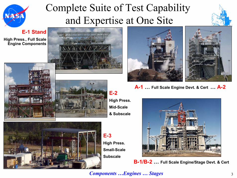
The NASA John C. Stennis Space Center (SSC) is located in Hancock County, MS and one aspect of its mission is the management and operation of a comprehensive and unique set of test facilities and test capabilities. A wide range of rocket propulsion test work occurs at SSC including full-scale engine test activities at test facilities A-1, A-2, B-1 and B-2 as well as combustion device research and development activities at the E-Complex (E-1, E-2, E-3 and E-4) test facilities.3-13
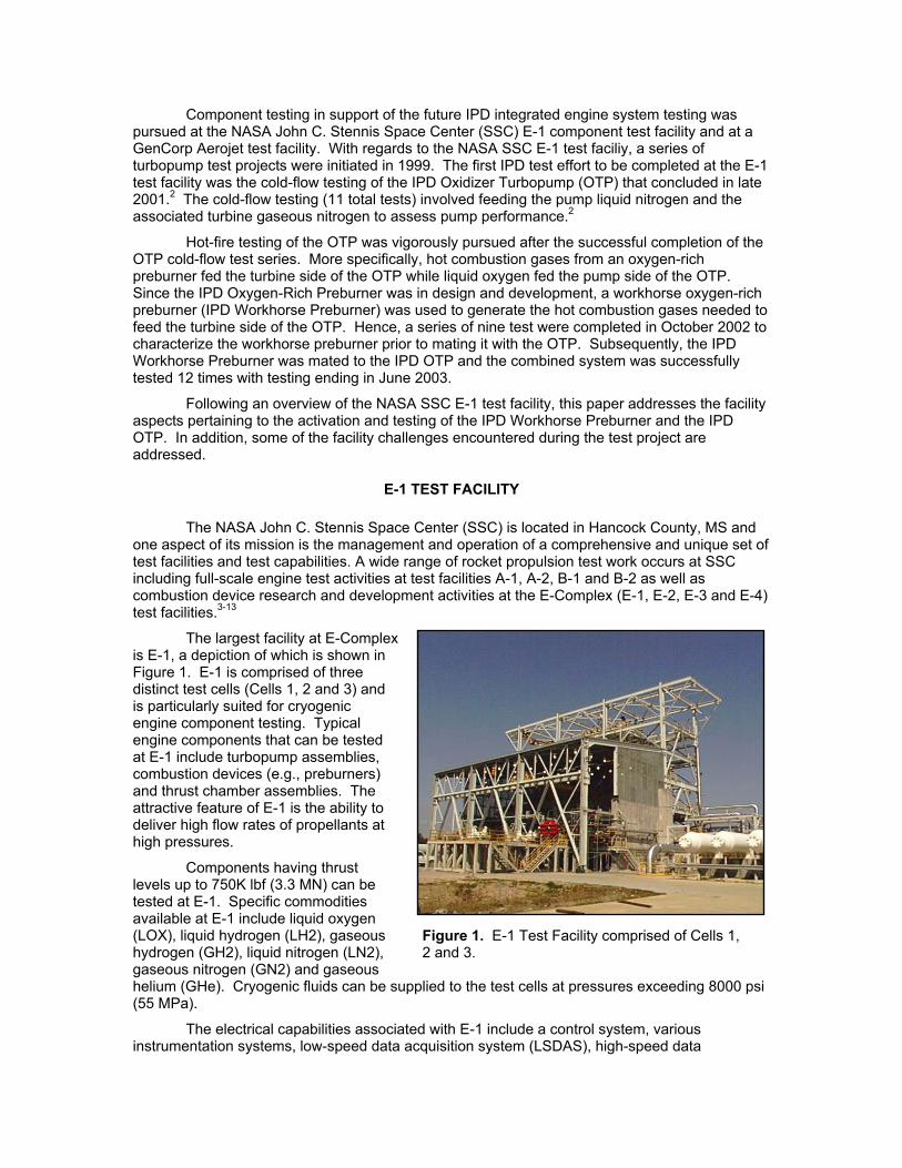
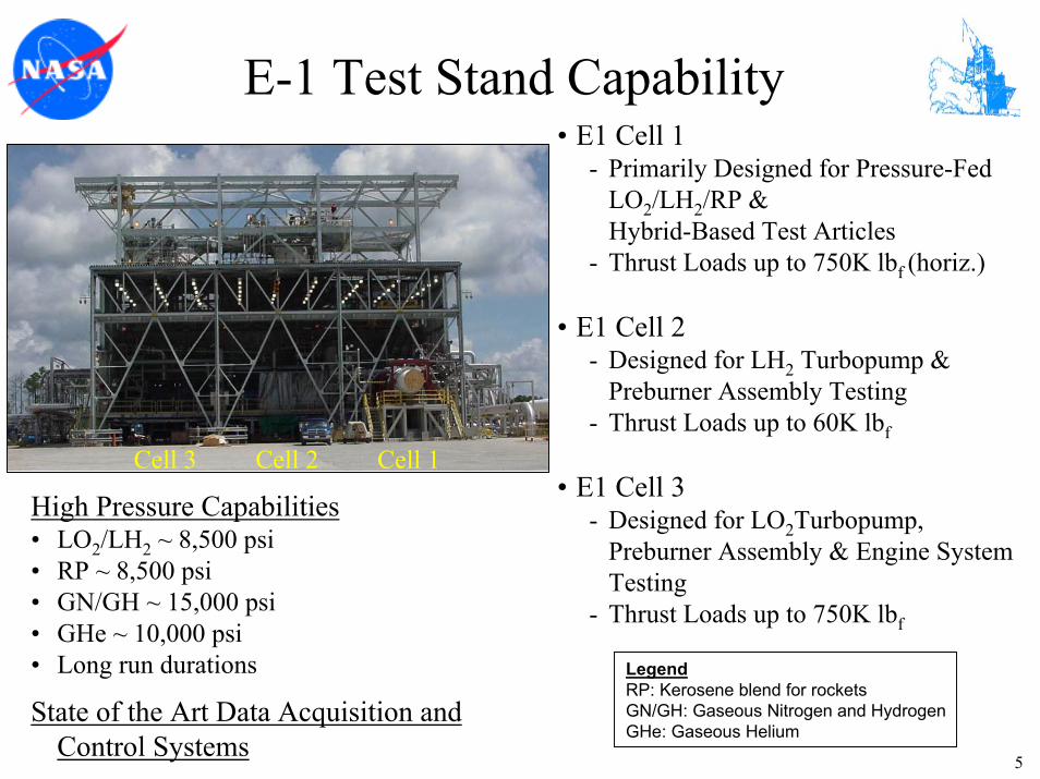
The largest facility at E-Complex is E-1, a depiction of which is shown in Figure 1. E-1 is comprised of three distinct test cells (Cells 1, 2 and 3) and is particularly suited for cryogenic engine component testing. Typical engine components that can be tested at E-1 include turbopump assemblies, combustion devices (e.g., preburners) and thrust chamber assemblies. The attractive feature of E-1 is the ability to deliver high flow rates of propellants at high pressures.
Components having thrust levels up to 750K lbf (3.3 MN) can be tested at E-1. Specific commodities available at E-1 include liquid oxygen (LOX), liquid hydrogen (LH2), gaseous hydrogen (GH2), liquid nitrogen (LN2), gaseous nitrogen (GN2) and gaseous helium (GHe). Cryogenic fluids can be supplied to the test cells at pressures exceeding 8000 psi (55 MPa).
Figure 1. E-1 Test Facility comprised of Cells 1, 2 and 3.
The electrical capabilities associated with E-1 include a control system, various instrumentation systems, low-speed data acquisition system (LSDAS), high-speed data
acquisition system (HSDAS), data processing capability, video system (low and high speed) and various power utilities.
Ancillary facility systems include a plume impingement area, hydraulic system and a communications system. In addition, each test cell is equipped with a deluge water system.
With regards to future work, efforts are currently either underway or planned to upgrade and enhance testing capabilities at E-1. The most significant upgrade currently underway is the addition of high-pressure hydrocarbon capability at E-1, potentially to 1Mlbf (4.4 MN) thrust, thereby enabling LOX/RP testing. A major upgrade of the gas pressurization systems is also underway. Other supporting enhancements are planned for the data acquisition and control systems (DACS).
TEST ACTIVITY DISCUSSION
After the completion of IPD Oxidizer Turbopump (OTP) cold-flow testing2, the E-1 Cell 3 test cell was prepared for the testing of the IPD Workhorse Preburner that employed liquid oxygen as the oxidant and gaseous hydrogen as the fuel. The fuel and oxidant was supplied to the preburner at high pressures. Once the IPD Workhorse Preburner was characterized, hot-fire testing of the IPD Oxidizer Turbopump (OTP) ensued at E-1 Cell 3. For the hot-fire OTP test series, the IPD Workhorse Preburner was mated to the IPD OTP. Liquid oxygen (LOX) and GH2 were supplied at high pressure to the preburner and the resulting high-pressure, high-temperature combustion gases were directed into the turbine side of the IPD OTP. Also, LOX at low pressure was supplied to the pump side of the IPD OTP.
In the sections that follow, aspects of the facility activation, including design and operational challenges, associated with the testing of the IPD Workhorse Preburner and the IPD OTP are outlined.
FACILITY ACTIVATION AND TESTING OF THE IPD WORKHORSE PREBURNER
A variety of facility activities from planning to design to fabrication/installation are part of the process of preparing for the testing of a particular test article. Upon project initiation, project management activities such as requirements definition and schedule development are undertaken. As requirements and project planning progress, design (e.g., structural, mechanical, electrical) activities are initiated. Facility and Special Test Equipment (STE) designs are developed that allow the facility to meet the various test article interface requirements that have been previously established. Note that the STE is the hardware (e.g., piping) that connects the test facility to the test article hardware. Following the appropriate design reviews, the designed systems are fabricated and installed. The installed facility and STE systems are subsequently tested (i.e. activated) to verify that the systems meet all of the agreed upon requirements. Once the facility and the test article have been properly integrated and a successful Test Readiness Review (TRR) completed, the testing phase begins.
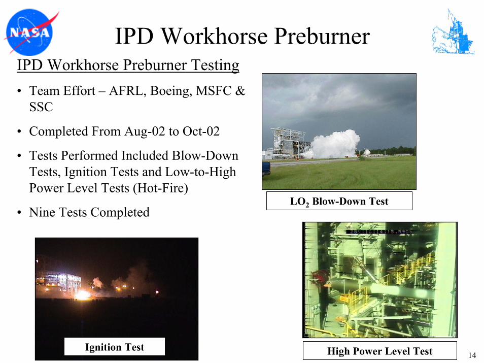
Facility activation involves testing the various facility systems to ensure that the facility can meet the test article requirements, for example, propellant flow rate, interface pressure(s) and interface temperature(s). Facility activation encompassing 20 formal tests were completed from February 2002 to July 2002 in preparation for IPD Workhorse Preburner testing. In general terms, of the 20 activation tests, 15 tests were conducted to characterize the facility high-pressure oxidant (LOX) system, four tests were conducted to characterize the high-pressure fuel (GH2) system and one test was conducted to characterize valve responses under simulated abort test conditions. Subsequent to facility activation, a total of nine IPD Workhorse Preburner tests were conducted from August 2002 to October 2002.
The IPD Workhorse Preburner required a high-pressure supply of LOX and GH2 as propellants and the test series encompassed ignition-only and low power level tests up through high power level tests. Ignition of the propellants was achieved with the aid of a pyrophoric fuel
mixture (15%/85% by weight) of Triethylaluminum/Triethylboron (TEA/TEB). Purge gases for the preburner included nitrogen and helium.
The high-pressure oxidant system, succinctly, consisted of a pressurization system (GN2), a vacuum-jacketed run tank containing LOX and various facility and STE piping and components that supplied LOX to the IPD Workhorse Preburner. For activation testing, the discharge from the system was routed through an activation pipe spool to a discharge line. The discharge line provided a means for flow measurement via a venturi, and provided for safely discharging the cold fluid to the atmosphere in front of the test cell.
From the vacuum-jacketed run tank, LOX was supplied to the preburner through a screen, cavitating venturi and finally a 10” (254 mm) hydraulically operated variable position valve (VPV). Installed in parallel with the main 10” valve was a 4” (102 mm) bypass line containing a 4” (102 mm) hydraulically operated VPV and an orifice plate. The bypass line was employed during the ignition portion of the combustion event to allow for a gradual flow initiation prior to opening the main valve.
The high-pressure oxidant system was designed to ensure the LOX flow rate was controlled by the facility without being affected by the operation of the workhorse preburner. During high power level tests, flow control was provided via cavitation at the bypass orifice during ignition and via cavitation at the venturi during main stage. During low power level tests, the main valve remained closed and flow control was provided via cavitation at the bypass valve during ignition and via cavitation at the bypass orifice during main stage. In this operating scheme, the demands on the design of the bypass orifice were particularly significant and challenging. The bypass orifice was fabricated from a Reflange R-CON blind seal ring. The bypass orifice was required to maintain structural integrity at very high differential pressures in some cases and to remain cavitated at relatively low differential pressures in other cases. In addition, the bypass orifice was a potential particle impact ignition hazard as it was a blunt face normal to the flow just a short distance downstream of the bypass valve. To mitigate the ignition risk, the standard orifice material was changed to a high strength Monel 500 to improve the ignition resistance. To withstand the high differential pressures, the standard seal ring thickness was increased. To remain cavitated at low differential pressure (high back pressure) conditions, the bypass orifice profile was modified and tested several times during activation to increase the pressure recovery factor to 75%. The final bypass orifice profile consisted of a rounded inlet with a discharge cone machined into the downstream side of the orifice, which significantly increased the exit plane area with respect to the throat area.
Overall, the approach utilized for each activation test associated with the high-pressure oxidant system was to ramp the valves and system pressures through as many target set points as possible to secure as much data as possible. In addition, a deliberate effort was made to determine the pressure ratio at which the cavitating venturi and cavitating orifice would no longer cavitate and control flow. This last point was vital since the flow rate measurements in the preburner inlet system relied upon the assumption that cavitation occurred.
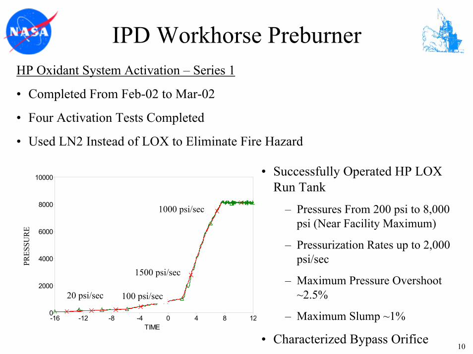
The first series of four activation tests treating the high-pressure oxidant system were performed in February 2002 and March 2002. These tests were performed with liquid nitrogen with the primary objectives of operating the run tank in a stable and repeatable manner to pressures exceeding 8000 psia (55 MPa) and to characterize the main and bypass flow valves. Since the objectives of the initial tests did not specifically require LOX, liquid nitrogen was used as the operating fluid since its properties are similar to those of LOX and the risk of an oxygen-based fire is eliminated. The activation tests were successful in that the run tank was operated at various pressures from 200 psia (1.4 MPa) to about 8000 psia (55 MPa) at various pressurization ramp rates up to 2000 psi/sec (14 MPa/sec) while minimizing pressure overshoot and slump (2.5% and 1%, respectively). In addition, the bypass line orifice was characterized and was further modified to achieve a greater pressure recovery factor as referred to in the preceding paragraphs.
A second series of seven activation tests treating the high-pressure oxidant system were performed from April 2002 to June 2002. The objectives of this activation series were similar to those in the first series. Improvements were made to the bypass orifice and a number of valve settings were tested to further minimize the overshoot and slump associated with operating the run tank. Once again LN2 was used as the working fluid for safety considerations. Another benefit of performing activation flows using LN2 is to flush the pipe system of any potential undesirable particulates in a safe manner. The screen prior to the main oxidant and bypass valves captured any potential undesirable particulate. The seven activation tests were successfully completed and the data procured allowed for the planning of activation tests employing LOX.
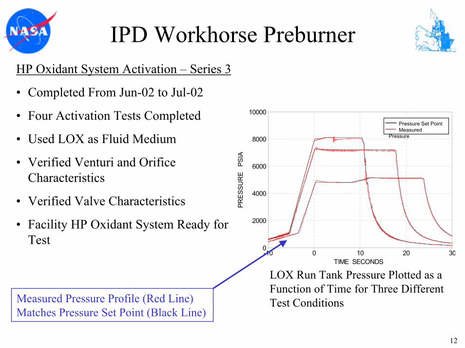
A third and final series of four activation tests treating the high-pressure oxidant system were performed in June 2002 and July 2002. For these activation tests, LOX was employed as the fluid medium. The objectives included verification of discharge coefficients and pressure recovery of the venturi and bypass orifice and to successfully operate the system under all planned test conditions including ignition and main stage regimes. More specifically, flow rate, system pressures and temperatures would be validated against the requirements for each expected test condition. As an example, Figure 2 displays the run tank set point pressure and actual pressure as a function of time for three different test conditions. For each activation test, the pressure in the run tank is increased to a given set pressure, the set pressure is maintained for a given duration while interface valves are opened and propellant flow is initiated. At the end of the planned duration, the interface valves are closed to halt the propellant flow and the pressure is subsequently vented from the system. For the cases shown in Figure 2, the run tank pressure was controlled very well with respect to the set point and run tank pressures exceeding 8000 psia (55 MPa) were achieved. The typical ramp rate to the run tank set pressure was about 1000 psi/sec (6.9 MPa/sec). Although not shown in Figure 2, the LOX flow rate and temperature requirements associated with each activation test were likewise successfully met. In addition, ramping the run tank pressure while flowing propellant was successfully demonstrated.
PRES
SUR
E P
SIA
-10 0 10 20 30
10000
8000
6000
4000
2000
0
TIME SECONDS
Pressure Set Point Measured Pressure
Figure 2. The run tank (LOX) pressure (psia) plotted as a function of time for three different test conditions. Each set of lines represents the run tank pressure set point (black line) and the measured pressure profile (red line) for a given simulated IPD Workhorse Preburner test condition. The set point and measured pressure profile agree very well.
With the completion of the high-pressure oxidant system activation, the facility efforts were focused upon activating the high-pressure fuel system that would deliver GH2 to the IPD Workhorse Preburner.
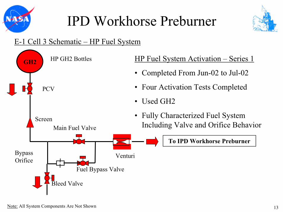
High-pressure GH2 was supplied at ambient temperature from three pressure vessels. A main and bypass line were used to supply the preburner with fuel (GH2). Fuel was fed through
the bypass line and an associated calibrated orifice during the ignition stage of the combustion event. Once ignition was validated within the preburner, additional fuel was supplied to the preburner using the main line coupled with a calibrated venturi. Note that during activation testing, a pipe spool was used to connect the preburner fuel inlet pipe to the facility high-pressure gaseous hydrogen vent system and finally to the high-pressure flare stack where the gaseous hydrogen was combusted.
Four high-pressure fuel system (GH2) blow-down activation tests were performed between June 2002 and July 2002 with the objectives of characterizing the fuel delivery system, obtaining the discharge coefficients for the installed orifices and demonstrating stable closed loop pressure control during ignition and main stage regimes. The activation objectives were met and the fuel system was fully characterized for the expected preburner power levels to be tested.
A total of nine IPD Workhorse Preburner tests were conducted from August 2002 to October 2002. The early tests were focused upon the introduction of the propellants into the preburner and the ignition sequence and characteristics of the combustion event. The later tests were performed at increasingly higher power levels.
An issue with the main oxidant valve (10” VPV) developed during the first test of the IPD Workhorse Preburner. While chilling the high-pressure oxidant facility system, a leak developed in the main oxidant valve allowing LOX to enter the preburner. Since this condition was undesirable, the first test was stopped. The main oxidant valve was subsequently removed from the system for detailed inspection and repair. Unfortunately, the 10” VPV had sustained internal damage and could not be repaired in a timely fashion. Therefore, blind hubs were installed in place of the main oxidant valve. Ignition testing and low power level testing then continued unimpeded since the bypass oxidant valve (4” VPV) supplied all of the LOX to the preburner for these tests. After completion of the low power level tests, a second 4” VPV was installed to serve as the main oxidant valve in place of the 10” VPV. Enough data had been collected during activation on the cavitating venturi to ensure that it would remain cavitated even with the added downstream pressure loss across the smaller main oxidant valve. Therefore, no further activation tests were needed due to the main oxidant valve replacement. Hence, for the high power level tests, LOX was supplied to the preburner via two identical 4” VPVs, the main and bypass oxidant valves. This arrangement proved very successful as the remaining preburner tests were completed.
E-1 FACILITY HYDRAULIC SYSTEM
One of the greatest challenges associated with operating a test facility is maintaining the health of the primary propellant systems as well as the test critical support systems such as a hydraulic system. The challenge emerges due to the fact that the operating conditions of the various system components are extreme (e.g., high pressure) and due to the fact that many of the components and systems are unique. The initiation of hot-fire testing of the IPD OTP was delayed due to an issue that developed with the E-1 hydraulic system, the details of which are disclosed next.
During routine facility system maintenance prior to IPD Workhorse Preburner Test 2, water was discovered in the E-1 hydraulic system. Succinctly, the E-1 hydraulic system consists of three main pumps and a jockey pump with a 750 gallon (2839 l) reservoir supplying hydraulic fluid (MIL-83282 Hydraulic Oil) to primarily facility and special test equipment (STE) valves throughout Cells 1, 2 and 3. It should be noted that the hydraulic fluid pipe system is rather unique and complex as it is comprised of over 10,000 ft (3048 m) of pipe and tubing and over 400 components.
The hydraulic fluid was cooled using a water-cooled heat exchanger contained in the hydraulic fluid reservoir. Investigation into the source of the water contamination led to the steel and copper brazed heat exchanger. The heat exchanger had developed an internal joint leak allowing cooling water to enter the hydraulic fluid. The heat exchanger was replaced and the system headers were drained and purged. New hydraulic fluid was added to the system and
subsequently cycled through paper filters bringing the water and particulate content of the hydraulic fluid back to near specification limits. The workhorse preburner test series proceeded with increased monitoring of the hydraulic system and hydraulically actuated valves.
However, in retrospect, what occurred over the next several weeks was a gradual degradation of the condition of the hydraulic system due to the adverse effects of the water contamination of the hydraulic fluid. The effects of the contamination were not clearly evident through the workhorse preburner test series that concluded in October 2002. The only noticeable sign of hydraulic system degradation was a slight “wandering” behavior of the main fuel valve (MFV) while in the full open position during the final three tests. In general, the MFV valve position varied by less than 1.5% and this variation was likely due to hydraulic fluid contamination.
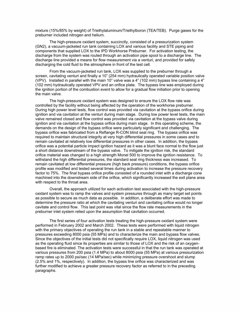
Concurrent with IPD Workhorse Preburner testing at E-1 Cell 3, activation testing was being pursued in Test Cells 1 and 2. The hydraulic valve systems in Cells 1 and 2 were affected more dramatically by the hydraulic system contamination with several valves deviating significantly from the commanded position. Inspection of the valves exhibiting the deviant behavior revealed water, particulate and sludge in the associated hydraulic system servos and filters. Inspection of hydraulic-based valves and other associated hydraulic components across the E-1 Test Facility revealed similar conditions. As an example, Figure 3 shows sludge accumulated on a hydraulic pump discharge filter. Consequently, a Stand-Down of all E-1 test operations occurred from November 2002 to February 2003. A multi-disciplinary team conducted a thorough investigation into the causes of the hydraulic system contamination and determined that the water in the hydraulic fluid from the failed heat exchanger resulted in significant contamination issues including microbial growth.
Remediation and corrective actions were vigorously initiated to clean the entire E-1 hydraulic system. More specifically, the entire system was disassembled and cleaned. Contaminated components were either repaired or replaced and all flex hoses were replaced with hard tubing. The hydraulic fluid was replaced and an additive was used to inhibit microbial growth. The risk of reintroducing water into the refurbished hydraulic system was greatly reduced with the transition to air-based hydraulic fluid cooling units using new state of the art hardware.
Along with hardware remediation, recurrence control measures were established to mthe risk of hydraulic fluid contamination. First, the number of instrumentation devices including pressure transducers and thermocouples were increased to allow for increased monitoring of the hydraulic system. In addition, the number of fluid sample ports in the system was increased. Improved processes and work instructions were developed and implemented for monitoring the hydraulic fluid and the system. Finally, a preventative maintenance program was established for current and future hydraulic components.
Figure 3. Abnormal accumulation of sludge on a hydraulic pump discharge filter.
itigate
Once the remediation efforts were complete, functional tests were successfully performed on all facility and STE hydraulic valves. In addition, “proof-of-readiness” performance testing prior to initiating IPD integrated preburner and oxidizer turbopump testing in Cell 3 was completed.
TESTING OF THE IPD INTEGRATED OTP
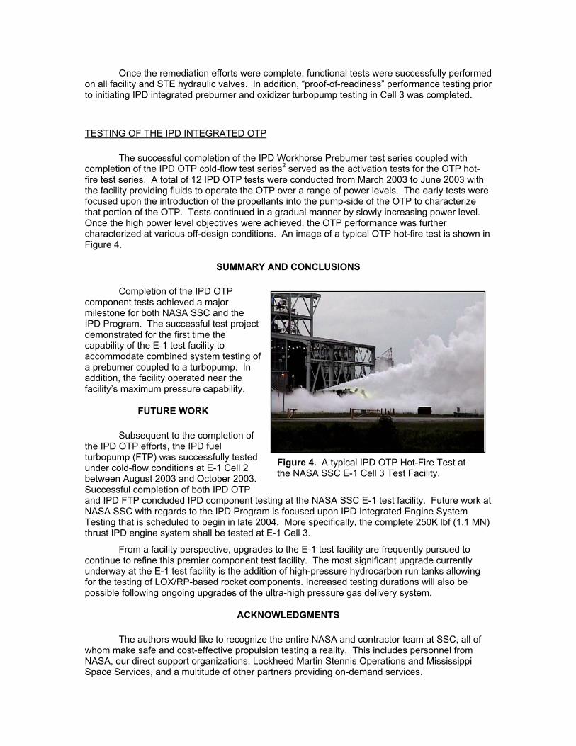
The successful completion of the IPD Workhorse Preburner test series coupled with completion of the IPD OTP cold-flow test series2 served as the activation tests for the OTP hot-fire test series. A total of 12 IPD OTP tests were conducted from March 2003 to June 2003 with the facility providing fluids to operate the OTP over a range of power levels. The early tests were focused upon the introduction of the propellants into the pump-side of the OTP to characterize that portion of the OTP. Tests continued in a gradual manner by slowly increasing power level. Once the high power level objectives were achieved, the OTP performance was further characterized at various off-design conditions. An image of a typical OTP hot-fire test is shown in Figure 4.
SUMMARY AND CONCLUSIONS
Completion of the IPD OTP component tests achieved a major milestone for both NASA SSC and the IPD Program. The successful test project demonstrated for the first time the capability of the E-1 test facility to accommodate combined system testing of a preburner coupled to a turbopump. In addition, the facility operated near the facility’s maximum pressure capability.
FUTURE WORK
Subsequent to the completion of the IPD OTP efforts, the IPD fuel turbopump (FTP) was successfully tested under cold-flow conditions at E-1 Cell 2 between August 2003 and October 2003. Successful completion of both IPD OTP and IPD FTP concluded IPD component testing at the NASA SSC E-1 test facility. Future work at NASA SSC with regards to the IPD Program is focused upon IPD Integrated Engine System Testing that is scheduled to begin in late 2004. More specifically, the complete 250K lbf (1.1 MN) thrust IPD engine system shall be tested at E-1 Cell 3.
Figure 4. A typical IPD OTP Hot-Fire Test at the NASA SSC E-1 Cell 3 Test Facility.
From a facility perspective, upgrades to the E-1 test facility are frequently pursued to continue to refine this premier component test facility. The most significant upgrade currently underway at the E-1 test facility is the addition of high-pressure hydrocarbon run tanks allowing for the testing of LOX/RP-based rocket components. Increased testing durations will also be possible following ongoing upgrades of the ultra-high pressure gas delivery system.
ACKNOWLEDGMENTS
The authors would like to recognize the entire NASA and contractor team at SSC, all of whom make safe and cost-effective propulsion testing a reality. This includes personnel from NASA, our direct support organizations, Lockheed Martin Stennis Operations and Mississippi Space Services, and a multitude of other partners providing on-demand services.
REFERENCES
1. Manski, D., Goertz, C., Sabnick, H., Hulka, J., Goracke, B. and Levack, D., “Cycles for Earth-to-Orbit Propulsion,” Journal of Propulsion and Power, Volume 14, Number 5 (September-October 1998). 2. Sass, J. P., Raines, N. G., Farner, B. R. and Ryan, H. M., “Facility Activation and Characterization For IPD Oxidizer Turbopump Cold-Flow Testing at NASA Stennis Space Center,” 52nd JANNAF Propulsion Meeting/1st Liquid Propulsion Subcommittee, Las Vegas, NV (May 10-13, 2004). 3. NASA Facts: “John C. Stennis Space Center, America’s Largest Rocket Propulsion Testing Complex,” NASA Facts, NASA SSC Public Affairs Office (May 2002). 4. Rahman, S., Hebert, B., Glorioso, M. and Gilbrech, R., “Rocket Propulsion Testing at Stennis Space Center: Current Capability and Future Challenges,” AIAA Paper 2003-0538, 39th AIAA/ASME/SAE/ASEE Joint Propulsion Conference, Huntsville, AL (July 20-23, 2003). 5. Jacks, T., and Beisler, M., “Expanding Hydrogen Peroxide Propulsion Test Capability at Stennis Space Center E-Complex,” AIAA Paper 2003-5041, 39th AIAA/ASME/SAE/ASEE Joint Propulsion Conference (July 20-23, 2003). 6. Bruce, R., Taylor, G. and Taliancich, P., “Rocket Propulsion Ground Testing with High Concentration Hydrogen Peroxide – Lessons Learned at NASA Stennis Space Center,” Proceedings, 5th Annual International Hydrogen Peroxide Propulsion Conference, Purdue University, pp. 257-264 (Sep. 15-19, 2002). 7. Bruce, R., Taylor, G. and Taliancich, P., “Ground Testing With High Concentration Peroxide-Lessons Learned,” AIAA 2002-3048, 22nd AIAA Aerodynamic Measurements Technology and Ground Testing Conference, St. Louis, MO (June 24-26, 2002). 8. Ryan, H., Canady, R., Sewell, D., Rahman, S. and Gilbrech, R., “E-4 Test Facility Design Status,” PERC 13th Annual Propulsion Symposium, Huntsville, AL (October 22-23, 2001). 9. Ryan, H., Solano, W., Holland, R. and Rahman, S., “Engineering the Future of Full-Scale Propulsion Testing,” AIAA Paper 2001-0746, 39th Aerospace Sciences Meeting, Reno, NV (January 8-11, 2001). 10. Ryan, H., Rahman, S. and Gilbrech, R., “Current and Future Rocket Propulsion Testing at NASA Stennis Space Center,” 11th Annual Symposium on Propulsion, Cleveland, OH (October 26-27, 2000). 11. Smith, K. and Wagner, D., “Development of Static Sea Level Test Facilities for RBCC Engines,” AIAA Paper 2000-3602, 36th AIAA/ASME/SAE/ASEE Joint Propulsion Conference & Exhibit, Huntsville, AL (July 17-19, 2000). 12. Rahman, S., Gilbrech, R., Lightfoot, R. and Dawson, M., “Overview of Rocket Propulsion Testing and NASA Stennis Space Center,” 11th Annual Symposium on Propulsion, Pennsylvania State University, University Park, PA (November 18-19, 1999). 13. Bruce, R., Taylor, G., Beckmeyer, D., Warren, S., Dracon, S., Powell, B., Goodwin, D., Rieder, P., Nichols, R., “Providing the Nation a Significant ‘High-Test Peroxide’ Propulsion Test Capability”, 2nd International H2O2 Conference Paper (1999).
1
Facility Activation and Characterization for IPD Workhorse Preburner and Oxidizer
Turbopump Hot-Fire Testing at NASA Stennis Space Center
J.P. Sass, N.G. Raines and H.M. Ryan
NASA John C. Stennis Space CenterSSC, MS
2
SSC Regional Map
3
Complete Suite of Test Capability and Expertise at One Site
• Tests Performed Included Blow-Down Tests, Ignition Tests and Low-to-High Power Level Tests (Hot-Fire)
• Nine Tests CompletedLO2 Blow-Down Test
Ignition Test High Power Level Test
15
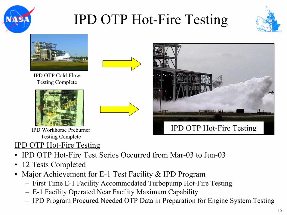
IPD OTP Hot-Fire Testing
IPD OTP Hot-Fire Testing
IPD OTP Cold-Flow Testing Complete
IPD Workhorse Preburner Testing Complete
IPD OTP Hot-Fire Testing• IPD OTP Hot-Fire Test Series Occurred from Mar-03 to Jun-03• 12 Tests Completed • Major Achievement for E-1 Test Facility & IPD Program
– First Time E-1 Facility Accommodated Turbopump Hot-Fire Testing– E-1 Facility Operated Near Facility Maximum Capability– IPD Program Procured Needed OTP Data in Preparation for Engine System Testing
16
E-1 Facility Systems
• Challenging Endeavor to Maintain the Health of Primary Propellant Systems (e.g., LH2, GH2, LOX, GN2) and Support Systems (Hydraulic, Deluge, Fire-Detect) of a Test Facility– Extreme Operating Conditions (e.g., High Pressures, High Flow Rates)– Unique or Near-Unique Components & Subsystems
• One Such Unique System is the E-1 Hydraulic System
– Fire Resistant & Temperature Tolerant– Lightweight & Easy Cleanup
• Distribution System Throughout Stand; 3 Cells• Over 10K ft of piping/tubing• Over 400 Components
17
E-1 Hydraulic System Contamination
• Failure of the Hydraulic System Heat Exchanger Allowed Cooling Water to Contaminate Hydraulic Fluid – Sludge & Slurries Developed in
Hydraulic System Network– Erratic Behavior & Performance
of Critical Valves Ensued
• Consequence - Test Operations Stand-Down From Nov-02 to Feb-03
Abnormal Accumulation of Sludge in Reservoir
Abnormal Accumulation of Sludge on Hydraulic Pump Discharge Filter
18
E-1 Hydraulic System Remediation
• Fault-Tree Investigation Completed - Root Causes & Vulnerabilities Established– Team Effort (AFRL, MSFC, Boeing & SSC) – Water Introduced into Hydraulic Fluid Resulted in Many Adverse Effects
– Cleaned Entire E-1 System; Repaired & Replaced Flawed or Questionable Components; Replaced Flex-Hoses with Hard Tubing
– Replaced E-1 Hydraulic Fluid & Used Additive to Inhibit Microbial Growth
– Full Functional Tests of E-1 Facility & STE Valves Performed• Recurrence Control
– Transitioned to Air-Cooled Hydraulic Units– Increased Instrumentation & No. of Fluid Sample Ports– Improved Process for Monitoring Hydraulic System– Improved Preventive Maintenance Program
19
E-1 Facility Valve Challenge
• 10” Main Oxidant Variable Position Valve (VPV)– Internal Leak Developed in VPV During the
First Workhorse Preburner Test– Undesirable Condition – LOX Entering
Preburner Prior to Test Start– Test Stopped & Valve Examined– Continue Testing Using Only Bypass Valve
for Low Power Level Tests– Internal Valve Damage Could Not Be
Repaired in a Timely Fashion• Replaced 10” Main Oxidant VPV with a
4” VPV Main Oxidant Valve– Arrangement Proved Successful Throughout
Test Sequence – Employed Two 4” VPV for High Power
Level Tests 10” Main Oxidant Valve
20
Acknowledgements
• NASA– Propulsion Test Directorate (PTD)– Center Operations Directorate– Office of Safety and Mission
Assurance
• Mississippi Space Services (MSS)
• Lockheed Martin Stennis Operations (LMSO)
StennisStennis… The Nation’s Partner of Choice for Rocket Propulsion Test… The Nation’s Partner of Choice for Rocket Propulsion Test